CN1006168B - Steam turbine high pressure vent and seal system - Google Patents
Steam turbine high pressure vent and seal system Download PDFInfo
- Publication number
- CN1006168B CN1006168B CN86106925.0A CN86106925A CN1006168B CN 1006168 B CN1006168 B CN 1006168B CN 86106925 A CN86106925 A CN 86106925A CN 1006168 B CN1006168 B CN 1006168B
- Authority
- CN
- China
- Prior art keywords
- rotor
- nozzle
- steam turbine
- nozzle box
- inner casing
- Prior art date
- Legal status (The legal status is an assumption and is not a legal conclusion. Google has not performed a legal analysis and makes no representation as to the accuracy of the status listed.)
- Expired
Links
Images
Classifications
-
- F—MECHANICAL ENGINEERING; LIGHTING; HEATING; WEAPONS; BLASTING
- F01—MACHINES OR ENGINES IN GENERAL; ENGINE PLANTS IN GENERAL; STEAM ENGINES
- F01D—NON-POSITIVE DISPLACEMENT MACHINES OR ENGINES, e.g. STEAM TURBINES
- F01D11/00—Preventing or minimising internal leakage of working-fluid, e.g. between stages
-
- F—MECHANICAL ENGINEERING; LIGHTING; HEATING; WEAPONS; BLASTING
- F01—MACHINES OR ENGINES IN GENERAL; ENGINE PLANTS IN GENERAL; STEAM ENGINES
- F01D—NON-POSITIVE DISPLACEMENT MACHINES OR ENGINES, e.g. STEAM TURBINES
- F01D5/00—Blades; Blade-carrying members; Heating, heat-insulating, cooling or antivibration means on the blades or the members
- F01D5/02—Blade-carrying members, e.g. rotors
- F01D5/08—Heating, heat-insulating or cooling means
-
- F—MECHANICAL ENGINEERING; LIGHTING; HEATING; WEAPONS; BLASTING
- F01—MACHINES OR ENGINES IN GENERAL; ENGINE PLANTS IN GENERAL; STEAM ENGINES
- F01B—MACHINES OR ENGINES, IN GENERAL OR OF POSITIVE-DISPLACEMENT TYPE, e.g. STEAM ENGINES
- F01B31/00—Component parts, details, or accessories not provided for in, or of interest apart from, other groups
- F01B31/06—Means for compensating relative expansion of component parts
Landscapes
- Engineering & Computer Science (AREA)
- Mechanical Engineering (AREA)
- General Engineering & Computer Science (AREA)
- Turbine Rotor Nozzle Sealing (AREA)
- Organic Low-Molecular-Weight Compounds And Preparation Thereof (AREA)
Abstract
A steam turbine having a chamber in the inlet end thereof adjacent the thrust balance piston and dummy ring formed so that the temperature is substantially reduced while the pressure is only slightly reduced to optimize the pressure temperature affect on the balance piston and rotor utilizing labyrinth seals and a static seal together with vent ports in fluid communication with the chamber and an area downstream of the first row of rotatable blades to provide a more efficient and reliable turbine.
Description
The invention relates to steam turbine, exactly, is about the packing of turbine high-pressure end and balancing orifice mode.
In order to obtain high efficiency, Ministry of Power Industry's gate open often need adopt many group modulating valve on Turbo-generator Set, variable entry nozzle steam flow area is regulated control.Like this, each entry nozzle chamber and the nozzle blade cascade that is attached thereto are all by separately modulating valve steam supply.Entry nozzle leaf grating and first order rotor moving blades lump together and have constituted governing stage.Yet high pressure steam from the nozzle outflow, behind the axial clearance place that arrives between nozzle and the movable vane, may leak along the leakage vapour passage between nozzle bottom and this two places nozzle labyrinth strip of moving blade ' s shroud band outer rim and the rotor, because leaking vapour, this does not pass through moving blades, not work done is so what of Steam loss are influential for Efficiency of Steam Turbine.To common, general be the Turbo-generator Set of the energy with the fossil class A fuel A, the temperature of this leakage vapour about about 520 ℃, and descends with the reduction of load under nominal working conditions.But even under the halfload state, the temperature of leaking vapour also is higher than 480 ℃.
In high-pressure turbine, from the steam that jet expansion leaks out, temperature is very high, and may pass the thrust balancing piston that flows to rotor between rotor and the nozzle box.Under given physical dimension,, descend with the temperature rising corresponding to the rotor material intensity of maximum creep shearing stress.Reduce the temperature of this leakage vapour so should try every means.No. 3206166 U. S. Patents have proposed a kind of way and have reduced near the vapor (steam) temperature of rotor.The way of this patent suggestion be the flow of steam direction in the governing stage is designed to opposite with steam flow direction in the later leaf gratings at different levels, a kind of new balancing orifice and sealing system have also been designed in addition, from the vapor stream that the jet expansion external leakage comes out, it can not directly be contacted with isolation with rotor.Single current high-pressure turbine and compound high pressure steam turbine all need a rotor thrust balance piston, its diameter and blade path mean screw diameter approximately equal.The thrust balancing piston of high pressure rotor is exposed in the steam of governing stage movable vane outlet, and the latter's temperature is in the scope of whole load variations, than low 25~55 ℃ approximately of jet expansion vapor (steam) temperatures.But the counter-flow arrangement mode of governing stage also has its shortcoming, promptly during leaf grating at different levels, need turn to 180 ° around the nozzle box after vapor stream comes out from governing stage and is directed into, and this will cause supplementary loss, so efficient is lower.Therefore, desirable scheme is to adopt the downflow type governing stage obtaining high efficiency advantage, and allows rotor be in than the obviously low temperature environment of the vapor (steam) temperature that spills from entry nozzle simultaneously.
No. 4242041 U. S. Patents have proposed to be applicable to the rotor cooling scheme of twin axial steam turbine, and it is by means of the high pressure steam Shu Shixian's that extracts out from the high pressure steam stream of governing stage or first order moving blades front and back two.
Main aim of the present invention is to point out a kind of mode of structure, and it has the high efficiency advantage of downflow type governing stage; For some key positions of rotor,, it is bathed in the lower vapor stream of temperature as near the nozzle box and thrust balancing piston; Simultaneously, the jet expansion steam flow that reduces at nozzle bottom packing place leaks, with the efficient of further raising assistant warden.
For reaching this purpose, implement the present invention in such steam turbine: it has an outer shell; An inner casing that is arranged in this outer shell; Part is arranged in the outer shell, part is arranged on the blade ring in the inner casing; A nozzle box component that is arranged in the inner casing, it has nozzle box and nozzle chunk, and its function is the moving blades of high pressure steam being guided into steam turbine; One has the vane group of a plurality of circumferential arrangement and the rotor of thrust balancing piston; The collar of close equalizing piston one end in inner casing; The labyrinth gland that is provided with between the collar and equalizing piston constitutes a rotating steam leakage restricting means between them; Its characteristics are that also an actionless packing is arranged between nozzle sets and blade ring; A labyrinth gland is arranged between nozzle box and rotor, obturage between them, realizing, so, inner casing, nozzle box, nozzle sets, blade ring, the collar, rotor, and above-mentioned respectively organize the chamber that packing is unified into a sealing, retraining the steam that acts on the equalizing piston; First order moving blades downstream part on blade ring also has a balancing orifice road, to link up this closed chamber, allows the vapor stream mistake.
The static packing of metal and the direct contacting point of metal is arranged between nozzle sets and the blade ring, is provided with labyrinth gland between nozzle box inner edge and rotor.Inner casing, nozzle box, nozzle sets blade ring, the collar and rotor, and respectively organize the airtight steam chest that packing has surrounded a sealing, retraining the steam that acts on the equalizing piston; Circumferentially arranged some ducts in the blade ring upper edge, linked up airtight steam chest, the downstream part at the one-level moving blades is opened in these ducts, for thrust balancing piston provides colder steam.
Some accompanying drawings are arranged behind this specification, and they just are used for illustrating the top-priority Application Example of this patent.By description, will make this patent invention explain clearlyer for it.In the accompanying drawing:
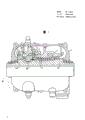
Fig. 1 is a kind of vertical half sectional view of steam turbine designed according to this invention;
Fig. 2 is the local amplification view of steam turbine shown in Figure 1.
Let us is carefully observed these accompanying drawings now, and this is a steam turbine, and it has an outer casing or claims the interior casing that 3, one of outer shells are arranged on 3 li of outer shells or claim inner casing 5, partly 5 li of inner casings, partly at the blade ring 7 of 3 li of outer shells.Nozzle box 9 is arranged on 5 li of inner casings, has nozzle box 9 and nozzle sets 13.Rotor 15 in the steam turbine has multistage circumferential vanes group or claims leaf grating 17, can freely rotate.Between moving blades 17, interting quiet circumferential vanes group or claim nozzle blade cascade 19, they are installed in 7 li of blade rings.End at inner casing 5 is provided with the collar 21, and the thrust balancing piston 23 that is installed on the rotor 15 nestles up the collar 21.
Arranging labyrinth gland 25 between the collar 21 and thrust balancing piston 23, it is made of some fins that are installed in a series of circumferential endless belt on the equalizing piston and inwardly stretch out from collar upper edge radial direction.Thereby fin is formed in dynamic high-pressure packing between the collar and the thrust balancing piston with these circumference endless belt interdigitations and radially forming very little gap.
Fig. 2 labyrinth gland 27 like the category that more clearly drawn, be arranged between nozzle box 9 and the rotor 15, it is installed in a plurality of circumference endless belt 31 on rotor 15 outer perimeter and 9 internal surface upper edge radial inward is stretched out from the nozzle box a plurality of fins 33 are formed by a string.Fin 33 is identical with endless belt 31, and is arranged on the radial direction core next-door neighbour with endless belt 31, thereby is formed in the dynamic high-pressure packing between nozzle box 9 and the rotor 15 together.
Between the turbine disk 37 on nozzle sets 13 and the rotor 15, also be provided with one group of labyrinth gland 35, contiguous first order leaf grating in its position or first order rotor annular blade row are formed in the dynamic high-pressure packing between nozzle sets 13 and the wheel disc 37.Another group labyrinth gland 39 is arranged between blade ring 7 and the first order moving blades outer ring shroud 40, bypasses before first order moving blades with the restriction high pressure steam.
The static seal structure 41 of a press fit is arranged, to prevent that steam is from leaking between them between nozzle sets 13 and blade ring 7.
Outlet port at adjacent first order moving blades, have many ducts 43 on the circumference of blade ring 7, like this steam by first order moving blades can pass it enter and one of filling by inner casing 5, blade ring 7, nozzle box 9, the collar 21, the steam chest 45 that thrust balancing piston 23 and rotor 15 surround, cause to form a pressure area here, and its temperature has been greatly diminished; This has just guaranteed the high efficiency advantage of the existing downflow type governing stage of this structure, make rotor thrust balance piston 23 obtain much cold steam supply again, act on the unlikely obvious reduction of pressure on the thrust balancing piston, the minimizing of the steam flow that bypasses before the first order moving blades will improve the efficient of governing stage.
Claims (3)
1, a kind of steam turbine, it forms-outer shell (3) by following part; An inner casing (5) that is arranged on outer shell (3) lining; Part is in the blade ring (7) that inner casing (5) lining, a part are in outer shell (3) lining; One be arranged on inner casing (5) lining, for sending vapour to the turbine rotor leaf grating, having the nozzle box (9,13) of nozzle box and nozzle sets parts (9,13); A rotor (15) that has an annular cascade (17) and a thrust balancing piston (23) on it; A collar (21) that is arranged on inner casing (5) lining near equalizing piston (23) one ends; Labyrinth-type excluder between the collar (21) and equalizing piston (23), limited leakage between them is formed rotatable packing, labyrinth gland structure (27,35) is positioned between nozzle box (9,13) and the rotor (15), between them, form sealing, being characterized as of this steam turbine: one group of static state gland seal structure (41) is arranged between nozzle sets (13) and blade ring (7); Like this, inner casing (5), nozzle box (9), nozzle sets (13), blade ring (7), the collar (21), and rotor (15), and above-mentioned gland seal structure, cooperation has formed the airtight steam chest (45) of a sealing, is retraining the steam that acts on the equalizing piston (23); Also be provided with a duct (43) on the blade ring (7), its position is in the downstream of first order rotor leaf grating (17), and its effect is fluid communication to be arranged with closed chamber (45).
2, by the described steam turbine of claim (1), it is characterized by, labyrinth gland (35,27) between nozzle box (13) and rotor (15) constitutes by following two groups: first group of labyrinth gland (35) is arranged near the first order moving blades upstream, between nozzle sets (13) and the rotor (15); Second group of labyrinth gland (27), setting between nozzle box (9) and rotor (15).
3, by the described steam turbine of claim (2), it is characterized by: second group of labyrinth gland between nozzle box (9) and rotor (15) is installed in the height that epitrochanterian circumferential endless belt (31) and some and these endless belt (31) one group of ring fin (33) alternately, that install with the center portion of endless belt (31) next-door neighbour formed and is forced down the leakage gland seal structure by a string on radial direction.
Applications Claiming Priority (2)
| Application Number | Priority Date | Filing Date | Title |
|---|---|---|---|
| US790,679 | 1985-10-23 | ||
| US06/790,679 US4661043A (en) | 1985-10-23 | 1985-10-23 | Steam turbine high pressure vent and seal system |
Publications (2)
| Publication Number | Publication Date |
|---|---|
| CN86106925A CN86106925A (en) | 1987-05-13 |
| CN1006168B true CN1006168B (en) | 1989-12-20 |
Family
ID=25151441
Family Applications (1)
| Application Number | Title | Priority Date | Filing Date |
|---|---|---|---|
| CN86106925.0A Expired CN1006168B (en) | 1985-10-23 | 1986-10-13 | Steam turbine high pressure vent and seal system |
Country Status (9)
| Country | Link |
|---|---|
| US (1) | US4661043A (en) |
| EP (1) | EP0220930B1 (en) |
| JP (1) | JPS62101801A (en) |
| KR (1) | KR950003058B1 (en) |
| CN (1) | CN1006168B (en) |
| CA (1) | CA1245164A (en) |
| DE (1) | DE3664510D1 (en) |
| ES (1) | ES2009789B3 (en) |
| IN (1) | IN164116B (en) |
Families Citing this family (14)
| Publication number | Priority date | Publication date | Assignee | Title |
|---|---|---|---|---|
| US4864810A (en) * | 1987-01-28 | 1989-09-12 | General Electric Company | Tractor steam piston balancing |
| US5056989A (en) * | 1990-10-01 | 1991-10-15 | Westinghouse Electric Corp. | Stage replacement blade ring flow guide |
| FR2831918B1 (en) * | 2001-11-08 | 2004-05-28 | Snecma Moteurs | STATOR FOR TURBOMACHINE |
| EP1624155A1 (en) * | 2004-08-02 | 2006-02-08 | Siemens Aktiengesellschaft | Steam turbine and method of operating a steam turbine |
| DE102006013557B4 (en) * | 2005-03-30 | 2015-09-24 | Alstom Technology Ltd. | Rotor for a steam turbine |
| JP2009047122A (en) * | 2007-08-22 | 2009-03-05 | Toshiba Corp | Steam turbine |
| JP5509012B2 (en) * | 2010-09-16 | 2014-06-04 | 株式会社東芝 | Steam turbine |
| EP2554789A1 (en) * | 2011-08-04 | 2013-02-06 | Siemens Aktiengesellschaft | Steamturbine comprising a dummy piston |
| FR2980817A1 (en) * | 2011-09-30 | 2013-04-05 | Alstom Technology Ltd | INSTALLATION COMPRISING OPTIMIZED YIELD STEAM TURBINE MODULES. |
| CN102425531A (en) * | 2011-11-13 | 2012-04-25 | 王政玉 | Multi-energy jointly powdered engine |
| CN104153824B (en) * | 2014-07-25 | 2016-05-04 | 江苏金通灵流体机械科技股份有限公司 | The multistage air seal structure of turbine |
| EP2987952A1 (en) | 2014-08-20 | 2016-02-24 | Siemens Aktiengesellschaft | Steam turbine and method for operating a steam turbine |
| US10247029B2 (en) * | 2016-02-04 | 2019-04-02 | United Technologies Corporation | Method for clearance control in a gas turbine engine |
| CN107725119B (en) * | 2017-12-06 | 2024-01-12 | 中国船舶重工集团公司第七0三研究所 | Nested vapor seal balance structure of high-pressure chamber |
Family Cites Families (15)
| Publication number | Priority date | Publication date | Assignee | Title |
|---|---|---|---|---|
| US2294983A (en) * | 1941-04-29 | 1942-09-08 | Westinghouse Electric & Mfg Co | Steam turbine apparatus |
| US2304994A (en) * | 1941-06-20 | 1942-12-15 | Westinghouse Electric & Mfg Co | Turbine cylinder cooling |
| US2467818A (en) * | 1947-11-29 | 1949-04-19 | Gen Electric | High-temperature turbine casing arrangement |
| US2524724A (en) * | 1948-10-07 | 1950-10-03 | Westinghouse Electric Corp | Turbine apparatus |
| US2796231A (en) * | 1954-03-24 | 1957-06-18 | Westinghouse Electric Corp | High pressure steam turbine casing structure |
| US2888240A (en) * | 1956-03-07 | 1959-05-26 | Allis Chalmers Mfg Co | Fluid cooled barrel cylinder for turbines |
| US2920867A (en) * | 1957-01-22 | 1960-01-12 | Westinghouse Electric Corp | Reheat turbine apparatus |
| US3189320A (en) * | 1963-04-29 | 1965-06-15 | Westinghouse Electric Corp | Method of cooling turbine rotors and discs |
| US3614255A (en) * | 1969-11-13 | 1971-10-19 | Gen Electric | Thrust balancing arrangement for steam turbine |
| BE786674A (en) * | 1971-07-26 | 1973-01-25 | Westinghouse Electric Corp | MULTI-ENCLOSURE TURBINE |
| JPS54163205A (en) * | 1978-06-16 | 1979-12-25 | Mitsubishi Heavy Ind Ltd | High and intermediate pressure combined turbine |
| US4242041A (en) * | 1979-01-15 | 1980-12-30 | Westinghouse Electric Corp. | Rotor cooling for double axial flow turbines |
| JPS56138405A (en) * | 1980-03-31 | 1981-10-29 | Fuji Electric Co Ltd | Gland steam pipe device for steam turbine |
| US4362464A (en) * | 1980-08-22 | 1982-12-07 | Westinghouse Electric Corp. | Turbine cylinder-seal system |
| IN162366B (en) * | 1984-03-23 | 1988-05-14 | Westinghouse Electric Corp |
-
1985
- 1985-10-23 US US06/790,679 patent/US4661043A/en not_active Expired - Lifetime
-
1986
- 1986-09-22 IN IN696/CAL/86A patent/IN164116B/en unknown
- 1986-10-13 CN CN86106925.0A patent/CN1006168B/en not_active Expired
- 1986-10-21 KR KR1019860008800A patent/KR950003058B1/en not_active IP Right Cessation
- 1986-10-21 CA CA000521009A patent/CA1245164A/en not_active Expired
- 1986-10-22 ES ES86308203T patent/ES2009789B3/en not_active Expired
- 1986-10-22 EP EP86308203A patent/EP0220930B1/en not_active Expired
- 1986-10-22 DE DE8686308203T patent/DE3664510D1/en not_active Expired
- 1986-10-23 JP JP61250939A patent/JPS62101801A/en active Granted
Also Published As
| Publication number | Publication date |
|---|---|
| EP0220930B1 (en) | 1989-07-19 |
| JPS62101801A (en) | 1987-05-12 |
| US4661043A (en) | 1987-04-28 |
| CA1245164A (en) | 1988-11-22 |
| CN86106925A (en) | 1987-05-13 |
| EP0220930A1 (en) | 1987-05-06 |
| KR950003058B1 (en) | 1995-03-30 |
| KR870004219A (en) | 1987-05-08 |
| ES2009789B3 (en) | 1989-10-16 |
| JPH0419364B2 (en) | 1992-03-30 |
| DE3664510D1 (en) | 1989-08-24 |
| IN164116B (en) | 1989-01-14 |
Similar Documents
| Publication | Publication Date | Title |
|---|---|---|
| US3291447A (en) | Steam turbine rotor cooling | |
| US3750398A (en) | Static seal structure | |
| US4820119A (en) | Inner turbine seal | |
| US5564896A (en) | Method and apparatus for shaft sealing and for cooling on the exhaust-gas side of an axial-flow gas turbine | |
| US1960810A (en) | Gas turbine | |
| CN1006168B (en) | Steam turbine high pressure vent and seal system | |
| US3529906A (en) | Static seal structure | |
| US4863343A (en) | Turbine vane shroud sealing system | |
| US3529904A (en) | Diaphragm seal structure | |
| US2630673A (en) | Cooling means for variable area nozzles | |
| US4311432A (en) | Radial seal | |
| US4541775A (en) | Clearance control in turbine seals | |
| US2962256A (en) | Turbine blade shroud rings | |
| US3746462A (en) | Stage seals for a turbine | |
| US1505647A (en) | Packing for elastic-fluid turbines and the like | |
| JPH03505247A (en) | Segment seal plate for turbine engine | |
| JPH06102988B2 (en) | Gas turbine engine casing temperature controller | |
| US2282894A (en) | Elastic fluid turbine | |
| GB1461965A (en) | Axial flow turbine structure | |
| JPS5941011B2 (en) | gas turbine | |
| GB1484951A (en) | Cooling system for a gas turbine engine | |
| GB1299684A (en) | Gas turbine engine seal structure | |
| US4655683A (en) | Stator seal land structure | |
| US5269648A (en) | Arrangement for controlling the flow cross section of a turbomachine | |
| CA2047275A1 (en) | Fully floating inlet flow guide for double-flow low pressure steam turbines |
Legal Events
| Date | Code | Title | Description |
|---|---|---|---|
| C06 | Publication | ||
| PB01 | Publication | ||
| C10 | Entry into substantive examination | ||
| SE01 | Entry into force of request for substantive examination | ||
| C13 | Decision | ||
| GR02 | Examined patent application | ||
| C14 | Grant of patent or utility model | ||
| GR01 | Patent grant | ||
| C19 | Lapse of patent right due to non-payment of the annual fee | ||
| CF01 | Termination of patent right due to non-payment of annual fee |