CN1006156B - Metal can end with plastics closure - Google Patents
Metal can end with plastics closure Download PDFInfo
- Publication number
- CN1006156B CN1006156B CN86106950.1A CN86106950A CN1006156B CN 1006156 B CN1006156 B CN 1006156B CN 86106950 A CN86106950 A CN 86106950A CN 1006156 B CN1006156 B CN 1006156B
- Authority
- CN
- China
- Prior art keywords
- metal
- closure
- cock body
- handle
- opening
- Prior art date
- Legal status (The legal status is an assumption and is not a legal conclusion. Google has not performed a legal analysis and makes no representation as to the accuracy of the status listed.)
- Expired
Links
Images

Classifications
-
- B—PERFORMING OPERATIONS; TRANSPORTING
- B65—CONVEYING; PACKING; STORING; HANDLING THIN OR FILAMENTARY MATERIAL
- B65D—CONTAINERS FOR STORAGE OR TRANSPORT OF ARTICLES OR MATERIALS, e.g. BAGS, BARRELS, BOTTLES, BOXES, CANS, CARTONS, CRATES, DRUMS, JARS, TANKS, HOPPERS, FORWARDING CONTAINERS; ACCESSORIES, CLOSURES, OR FITTINGS THEREFOR; PACKAGING ELEMENTS; PACKAGES
- B65D17/00—Rigid or semi-rigid containers specially constructed to be opened by cutting or piercing, or by tearing of frangible members or portions
- B65D17/50—Non-integral frangible members applied to, or inserted in, preformed openings, e.g. tearable strips or plastic plugs
- B65D17/506—Rigid or semi-rigid members, e.g. plugs
- B65D17/507—Rigid or semi-rigid members, e.g. plugs moulded in situ, e.g. during production of container
- B65D17/508—Rigid or semi-rigid members, e.g. plugs moulded in situ, e.g. during production of container and combined with a rigid or semi-rigid, e.g. metallic sheet and a moulded plastic body
Abstract
A metal can end with a tear-open plastics closure in which the closure has a plug part fitting into an aperture in the can end, a rim surrounding the plug part, and a pull tab, wherein a groove extends across the plug part and aligned grooves or interruptions extend across the rim to provide a hinge line allowing the tab and the adjacent portion of the plug part to pivot upwardly to provide venting of the can in a first stage of opening before full opening of the closure in a second stage. The closure is of the kind which is moulded on to the can end so as to totally enclose a downturned flange around the periphery of the aperture, and to be capable of being sheared against the flange on opening, and the residual thickness of the plastics material below the flange is greater in the main portion than in the vent portion of the closure to provide a temporary arrest after venting.
Description
The present invention relates to have horizontal handle,, particularly adorn the metal can that bears internal pressure of liquid, for example adorn the beverage of gassiness with the metal can end of peelable plastic closure sealing opening.
In the known structure, the closure of uniform cross-section is housed on the single opening of metal can end.Resemble known to us, when closure when an end of opening is torn, closure is opened very soon, and uncontrollable, be attended by simultaneously tedious noise and jar in the danger of content overflow.The known two hatch frames that have a relief hole and a tap hole, open successively in two holes, has reduced noise, and reduced overflow danger.But this complex structure has brought difficulty for the production of jar end wall.
Therefore, the object of the invention is to provide a kind of and seals single opening with closure, and the may command closure is opened, and reduces noise and the end wall that reduces the metal can of overflow danger.
According to the present invention, a kind of metal can end is provided, have on it one by reclinate angle staple around opening, flange is formed by the metal of jar end wall, this opening is by the sealing of peelable plastic closure.Said closure has the cock body that is assemblied on the opening.There is one to be arranged on the metal can end around the cock body, around the edge of opening, and a handle that links into an integrated entity with closure.The closure that is assemblied on the metal can end is surrounded flange fully, when mentioning handle, shears closure along flange, and opening is opened.Wherein, have a groove on closure, it passes the cock body of closure, and is vertical with the length direction of handle, so that form the broken line that makes the handle turnover, and the cock body part adjacent with handle can be with respect to the upwards turnover of other parts of cock body.Edge thickness on the same straight line is reduced or cuts off, and makes it not influence the turnover motion.Like this can first pressure release before closure is all opened, wherein the residual thickness under flange away from the handle part is bigger at the residual thickness under the flange than the adjacent part of shaking hands, and makes like this before closure is all opened, and temporarily stops shear action.In fact, the unlatching of this structure is by two process statuses, and first opening is along with temporarily stopping shearing, by the pressure release of sub-fraction opening, second opening is that opening is all opened, so in the opening opening process, noise is low, overflow is dangerous little.Under flange, have thicker plastic material away from the effect of the cock body part of handle by the metal can internal pressure, cause the plastic material creep, increased the reliability that stops seepage.
The cock body of closure at least its away from the counter-bending power of the cock body part of handle greater than the counter-bending power of jar end wall metallo-, make under the internal pressure effect, the arch distortion of metal can end occurs in the part that does not have opening, and this is because the cock body of closure has partly been strengthened the intensity of opening part.Between the metal can end surface of laterally shaking hands and being adjacent an angle is arranged, be easy to hold it like this and open opening.The cock body part is transferred along broken line, but does not deform with the cock body part of shaking hands adjacent, and feasible handle and metal can end are surperficial to be separated.
Suitable thickness can satisfy the counter-bending requirement of cock body.
Manufacture closure if use hard plastic material, when the edge also has same thickness,, not that the part of contiguous handle is transferred along broken line because the hardness of plastic material causes when lifting handle, but the closure integrally bending makes lid all open unintentionally when first state of unlatching.By this reason, be on the same linear position at the groove on edge and the cock body and slot, to reduce edge thickness, reduce its counter-bending power, perhaps cut off the edge, so that do not hinder the turnover campaign of cock body at all in this position.Use the cock body of the strong plastic material of resistant to bending stresses, help also to prevent that closure is all crooked or closure is all opened.
When the cock body and the opening of closure is extended, become part with parallel edges and nose circle.In this case, handle is along the nose circle horizontal expansion of cock body, and groove passes cock body, is arranged on and shakes hands between bonded assembly nose circle and the parallel edges part, and groove is split into V-arrangement, and the degree of depth is half of cock body thickness.
In amended scheme, second groove opened between the nose circle of parallel edges partial sum away from handle.Be reduced with the edge thickness of the closure of second groove on same straight line, perhaps the edge cut off, thereby form second broken line., and cut off to being not easy greatly greater than the thickness of parallel edges part below flange away from the residual thickness of the plastic material below flange of the nose circle part of handle.Closure still is connected with second broken line after unlatching like this, is retained on the metal can end surface.
The present invention also can be used on the end wall of other metal can.
Concrete structure of the present invention further describes by embodiment with reference to the accompanying drawings.
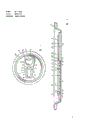
Fig. 1 is the front elevation that the metal can end of plastic closure is housed of the present invention.
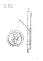
Fig. 2 is the transversal surface cutaway view of the metal can end among the Fig. 1 that amplifies.
Fig. 3 is the cutaway view that is arch with the same metal can end of Fig. 2 under the internal pressure effect.
Fig. 4 is the transversal surface cutaway view that the metal can end that is same as Fig. 2 is in first opening.
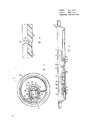
Fig. 5 is the front elevation of second embodiment of the Fig. 1 of being similar to of the present invention.
Fig. 6 is the transversal surface cutaway view of the metal can end that is in first opening that is similar to Fig. 4 shown in Figure 5.
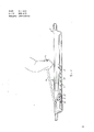
Fig. 7 is the front elevation of the 3rd embodiment of the Fig. 1 of being similar to of the present invention and Fig. 5.
Fig. 8 is the transversal surface cutaway view of amplification that is similar to the 3rd embodiment of Fig. 2.
Fig. 9 is the local transversal surface cutaway view that amplifies.
Figure 10 is the view that is similar to Fig. 8, and its expression closure is in first opening.
Figure 11 also is the view that is similar to Fig. 8, and its expression closure is in second opening.
In Fig. 1 to Fig. 4, metal can end 10 has one by plastic closure 12 osed top opening 11(Fig. 4).Closure 12 has with the cock body 14 of opening 11 assemblings with the transverse annular of closure formation one shakes hands 15.The decurved flange 16 that opening 11 has a circle to be made of the metal of metal can end 10.Closure is mounted to and surrounds entire flange 16 on the end wall, and has the inner edge 171 that leans against the metal can inside face.When handle 15 is pulled up, because the shear action of the lower surface 161 of flange 16 is opened closure.Closure 12 also has the edge 17 around cock body 14 that leans against metal can 10 outside faces.Clearly illustrate that among Fig. 1 that the cock body 14 of closure (being assemblied on the opening 11) is microscler, it has edge parallel to each other 18,19 and ring edge 20,21.
The upper surface 141 of cock body 14 is lower than the plane at edge 17, so that be fixedly mounted on the plane 101 of metal can end.Groove 22 is arranged on the closure, it is vertical with the length direction of closure, pass on the outside face 141 of cock body 14.Groove 22 is on cock body 14, between the round nose of contiguous handle 15 and cock body parallel edges part, pass, thereby form the broken line that handle 15 and adjacent with it cock body part 23 are transferred with respect to other parts of cock body, thereby reach first opening in whole process of opening closure shown in Figure 4.
The cross section of groove 22 is V-arrangements, clearly illustrates that in Fig. 2 and Fig. 3, and its thickness equals half of cock body 14 thickness.
Transfer with respect to other parts for the part 23 that edge 17 is influenced on the cock body 14, use hard plastic material resemble nylon.On edge 17, have groove 24,25 along groove 22 collinear positions reducing thickness, its groove depth is greater than half of edge 17 thickness.The reducing of thickness makes the surplus material of groove 24,25 bottoms can break apart when cock body part 23 is upwards transferred.
Thereby, resemble Fig. 2 to shown in Figure 4, the thickness of the part 23 of being close to handle 15 on the cock body reduces, make that the residual thickness of part 23 below the lower surface 161 of flange 16 of closely shaking hands near the residual thickness of cock body part 29 the lower surface 161 of flange 16 below away from groove 22 another sides of handle 15 is big, resemble shown in Figure 4, design-calculated, can make after 23 unlatchings of a cock body part in opening the process of metal can than the remainder of heavy gauge like this, and shear action temporarily stops.And then the residual thickness below the Pipe Flange 16 is not much, only needs to increase a little application force, shears along the parallel edges 18,19 of cock body 14, and the main body of closure just can be cut off, and opens opening then.Discontinuous application force has reduced because continuous sheared edge 18,19 causes content under the internal pressure effect, the danger of flowing out the opening from the jar end wall.
As shown in Figure 3, the metal can pressure inside makes metal can end be arch.
If cock body 14 is quite thin materials, its bending strength is lower than the bending strength of metal can end, under the internal pressure effect, the arch of metal can end will mainly occur in opening 11 places, cock body 14 bears most of distortion, and cause that by internal pressure the distortion of the metal can end 28 below handle 15 can be very not big.The handle 15 that leans against metal can end does not deform, and it is difficult for being booked like this, particularly when the handle of molding during to the metal can end surface tilt.To situation shown in Figure 4, cock body 14 has enough thickness, and counter-bending force rate metal can end 10 is big at Fig. 1.When metal can end resembles as shown in Figure 3, when arching upward under the internal pressure effect, except that groove 22, big distortion does not take place in cock body 14, especially away from the not distortion of cock body part 29 of handle 15, and the metal can end part around having strengthened.On the other hand, moderate finite deformations take place in the following metal can end part 28 of handle, and this is because thicker cock body 14 has been strengthened the opening 11 counter-bending power of metallo-on every side, arch is out of shape mainly occurs on metal can end central authorities and the broken line.Thereby, resemble shown in Figure 3, the handle 15 with adjacent metal jar end wall one angle is arranged, be easy to hold it, open opening.
It should be noted that the part 29 of cock body 14 has higher counter-bending power.In fact this part is 29 thicker than other parts on the cock body 14, has many good qualities like this.And then cock body part 29 thickness are big, and its result has increased on the cock body away from the plastic material thickness under the flange 16 of handle one end, and the supplementary protection of antiseep is provided.This protection also can be reached by the creep of plastic material under the effect of metal can internal pressure.
When metal can did not bear internal pressure, its end wall central authorities were planes, did not have the arching distortion, and handle 15 resembles and abuts against as shown in Figure 2 on the metal can part 28, helped reducing untapped metal can like this and heaped the space.
Fig. 5 and Fig. 6 have described a kind of version, and not merely there is groove 24,25 at edge 17, and are cut off with 26,27 places, position on the groove 22 same straight lines.Make it in opening procedure shown in Figure 6, not play any inhibition.The others present embodiment is said similar to Fig. 1 to Fig. 4.
Fig. 7 to Figure 11 has described the 3rd embodiment, and metal can 10 has opening 11 and flange 16, and these represent equally with previous drawings, and closure 30 comprises edge 32 and the cock body 31 with the flange 16 that surrounds foregoing metal can end 10.Constitute around the edge 32 and on the left side the edge annular lateral plate or the side arm 34 that connect together just as handle 33 shown in the figure.Finger handle 35 is on the right of handle 33.And the corresponding groove 36 of the groove among Fig. 1 to Fig. 6 passes cock body 31 and opens the annular pressure release part 37 of on the left side and have between the base portion 39 of parallel edges.Groove 38 on the edge 32 and groove 36 are on same straight line, the thickness of parallel edges portion 39 is bigger than pressure release part 37 on the cock body, increasing parallel edges part 39 at flange 16 lower surfaces 161 place's thickness, thus as fwd embodiment after pressure release, temporarily stop shear action to take place.
In the present embodiment, another groove 40 open the parallel edges partial sum away from and the circular portion 41 of handle 33 bonded assembly circular portions between, drive and pass edge 32 at the groove on the edge 42,43 and be on the same straight line, thereby form second broken line with groove 40.Circular portion 41 at the residual thickness under the flange 16 greater than the parallel edges part residual thickness under flange 16.And shear to being not easy greatly.Like this, the unlatching of closure 30 is by shown in Figure 10, and again through behind of short duration the stopping, by second opening, as shown in figure 11, base portion 39 is opened by the first opening pressure release.When base portion 39 when the second broken line changes, by the end of circular portion 41, base portion 39 is retained on the metal can end, content can be poured out from jar.
Claims (7)
1, a kind of end wall of metal can, the reclinate flange that it has an opening and constitutes around the end wall metal by jar of opening, and the peelable plastic closure of sealing opening, said closure has a cock body that is assemblied on the opening, one leans against the edge that centers on cock body on the metal can end surface, and one constitute the horizontal handle of one with closure, closure is assemblied on the metal can end flange is surrounded, and when mentioning handle, closure is sheared by flange and is opened opening, wherein, have the groove of the cock body that passes closure on the closure, this groove is vertical with the length direction of handle, so that form a broken line, make handle and adjacent plug body part thereof divide upwards turnover of other parts with respect to cock body, be reduced or cut off with the edge thickness on the same straight line of groove, make it not influence the turnover motion, like this can be before closure be all opened, make a jar pressure release, it is characterized in that: away from shaking hands partly, the residual thickness of the plastic material under flange greater than with the thickness of handle adjacent part, make closure temporary transient shear action that stops before all opening.
2, according to the end wall of the said metal can of claim 1, it is characterized in that: on the cock body of closure, at least the cock body counter-bending force rate metal can end partly away from handle is big, so that under the internal pressure effect, the metal can ends arching, said cock body is partly strengthened intensity of metal can ends around its, makes the arch distortion occur in other parts of metal can end, and laterally handle has an angle with the metal can ends surface of adjacent arching.
3, according to the end wall of the said metal can of claim 1, it is characterized in that: cock body and opening prolong becomes the part that parallel edges and nose circle are arranged, handle crosses out from the nose circle of cock body, and groove passes cock body, is opened in and shakes hands between bonded assembly nose circle and the parallel edges part.
4, according to the end wall of the said metal can of claim 2, it is characterized in that: cock body and opening prolong becomes the part that parallel edges and nose circle are arranged, handle crosses out from the nose circle of cock body, and groove passes cock body, is opened in and shakes hands between bonded assembly nose circle and the parallel edges part.
5, according to the end wall of the said metal can of above-mentioned arbitrary claim, it is characterized in that: groove is split into V-arrangement, and its degree of depth equals half of cock body thickness.
6, according to the end wall of the said metal can of the arbitrary claim of above-mentioned 1-4, it is characterized in that: handle is an annular arrangement, is useful on the thin wing sheet of the plastic material of pad on user's finger of user's gripping in the annular the inside.
7, according to the end wall of claim 3 or 4 said metal cans, it is characterized in that: second groove passes cock body and opens between the nose circle of parallel edges partial sum away from handle, be reduced or cut off with the edge thickness of the closure of second groove on same straight line, thereby form second broken line, away from the nose circle part plastic material thickness below flange of handle greater than the parallel edges part, thickness below flange and being cut off to being not easy greatly, after closure is unlocked like this, still be connected with the second broken line, be retained on the metal can end surface.
Applications Claiming Priority (2)
| Application Number | Priority Date | Filing Date | Title |
|---|---|---|---|
| GB858523262A GB8523262D0 (en) | 1985-09-20 | 1985-09-20 | Metal can end |
| GB8523262 | 1985-09-20 |
Publications (2)
| Publication Number | Publication Date |
|---|---|
| CN86106950A CN86106950A (en) | 1987-07-15 |
| CN1006156B true CN1006156B (en) | 1989-12-20 |
Family
ID=10585487
Family Applications (1)
| Application Number | Title | Priority Date | Filing Date |
|---|---|---|---|
| CN86106950.1A Expired CN1006156B (en) | 1985-09-20 | 1986-09-19 | Metal can end with plastics closure |
Country Status (17)
| Country | Link |
|---|---|
| US (1) | US4674649A (en) |
| EP (1) | EP0220820B1 (en) |
| JP (1) | JPS6278051A (en) |
| CN (1) | CN1006156B (en) |
| AT (1) | ATE52234T1 (en) |
| AU (1) | AU590329B2 (en) |
| BR (1) | BR8604496A (en) |
| CA (1) | CA1269053A (en) |
| DE (1) | DE3670617D1 (en) |
| ES (1) | ES2000903A6 (en) |
| GB (2) | GB8523262D0 (en) |
| GR (1) | GR862396B (en) |
| MY (1) | MY100044A (en) |
| NO (1) | NO863725L (en) |
| NZ (1) | NZ217629A (en) |
| SU (1) | SU1500149A3 (en) |
| ZA (1) | ZA866896B (en) |
Families Citing this family (50)
| Publication number | Priority date | Publication date | Assignee | Title |
|---|---|---|---|---|
| GB8523263D0 (en) * | 1985-09-20 | 1985-10-23 | Metal Box Plc | Making metal can ends |
| US4804104A (en) * | 1987-05-01 | 1989-02-14 | Adolph Coors Company | System for forming an opening in a container end member |
| US4733793A (en) * | 1987-05-01 | 1988-03-29 | Adolph Coors Company | System for forming an opening in a container end member |
| GB8724245D0 (en) * | 1987-10-15 | 1987-11-18 | Metal Box Plc | Metal can ends |
| NL8702497A (en) * | 1987-10-19 | 1989-05-16 | Michael John Mary Doyle | END WALL WITH DETACHABLE CLOSING LIP FOR PRESSURIZED HOLDER. |
| GB8815486D0 (en) * | 1988-06-29 | 1988-08-03 | Grace W R & Co | Container closures & materials for use in these |
| US4877149A (en) * | 1988-11-30 | 1989-10-31 | Showa Denko Kabushiki Kaisha | Scored container top |
| GB8903573D0 (en) * | 1989-02-16 | 1989-04-05 | Metal Box Plc | Can end |
| US5054642A (en) * | 1989-03-15 | 1991-10-08 | Tenryu Chemical Industry Co., Ltd. | Lid device for wide-mounted container and method of producing the same |
| JPH0712273Y2 (en) * | 1989-03-15 | 1995-03-22 | 天龍化学工業株式会社 | Wide-mouth container lid device |
| US5152421A (en) * | 1991-09-12 | 1992-10-06 | Krause Arthur A | Beverage can end with reduced material requirements |
| US5353943A (en) * | 1993-03-15 | 1994-10-11 | Sonoco Products Company | Easy-opening composite closure for hermetic sealing of a packaging container by double seaming |
| JP3596684B2 (en) * | 1994-05-31 | 2004-12-02 | 日本テトラパック株式会社 | Pull tab for liquid container |
| GB9510515D0 (en) * | 1995-05-24 | 1995-07-19 | Metal Box Plc | Containers |
| USD406236S (en) * | 1995-10-05 | 1999-03-02 | Crown Cork & Seal Technologies Corporation | Can end |
| US6026971A (en) * | 1995-10-10 | 2000-02-22 | Lundgren; James F. | Lever operated opener for container |
| US5660302A (en) * | 1995-12-08 | 1997-08-26 | Rieke Corporation | Removeable plastic plug with pull ring |
| US6399170B1 (en) | 1997-12-24 | 2002-06-04 | Owens-Illinois Closure Inc. | Plastic closure with compression molded barrier liner |
| US6371318B1 (en) | 1997-12-24 | 2002-04-16 | Owens-Illinois Closure Inc. | Plastic closure with compression molded sealing/barrier liner |
| US6102243A (en) | 1998-08-26 | 2000-08-15 | Crown Cork & Seal Technologies Corporation | Can end having a strengthened side wall and apparatus and method of making same |
| USD419873S (en) * | 1998-09-12 | 2000-02-01 | Giuseppe Piccione | Can top |
| US7380684B2 (en) * | 1999-12-08 | 2008-06-03 | Metal Container Corporation | Can lid closure |
| US6561004B1 (en) | 1999-12-08 | 2003-05-13 | Metal Container Corporation | Can lid closure and method of joining a can lid closure to a can body |
| US6499622B1 (en) * | 1999-12-08 | 2002-12-31 | Metal Container Corporation, Inc. | Can lid closure and method of joining a can lid closure to a can body |
| MXPA04006730A (en) * | 1999-12-08 | 2005-03-31 | Metal Container Corp | Metallic beverage can end with improved chuck wall and countersink. |
| BR0001936B1 (en) * | 2000-03-21 | 2010-06-01 | improvement introduced in sealing-lid of powdered or other metal food packaging. | |
| US20030132230A1 (en) * | 2001-03-12 | 2003-07-17 | Bruce Gitelman | Articulated tab opener for container |
| US6575325B2 (en) * | 2001-03-12 | 2003-06-10 | Robert G. Dickie | Articulated pull tab opener for container |
| US6419110B1 (en) | 2001-07-03 | 2002-07-16 | Container Development, Ltd. | Double-seamed can end and method for forming |
| KR200289188Y1 (en) | 2002-06-11 | 2002-09-13 | 전정욱 | Readily openable can lid |
| US6889862B2 (en) * | 2002-09-19 | 2005-05-10 | Ball Corporation | Large opening beverage container |
| US7021484B2 (en) * | 2004-01-23 | 2006-04-04 | Renner Herrmann S/A | Device inserted into the sealed lids of metal packaging for liquid products |
| PL1773522T3 (en) * | 2004-07-29 | 2011-04-29 | Ball Corp | Method and apparatus for shaping a metallic container end closure |
| WO2006036934A2 (en) | 2004-09-27 | 2006-04-06 | Ball Corporation | Container end closure |
| US7506779B2 (en) | 2005-07-01 | 2009-03-24 | Ball Corporation | Method and apparatus for forming a reinforcing bead in a container end closure |
| US7703624B2 (en) * | 2005-08-18 | 2010-04-27 | Stolle Machinery Company, Llc | Flexible tab, tooling for the manufacture of the flexible tab and method of manufacturing the flexible tab |
| JP5520232B2 (en) * | 2008-01-18 | 2014-06-11 | クラウン パッケイジング テクノロジー インコーポレイテッド | Can end |
| US8336728B2 (en) * | 2008-04-21 | 2012-12-25 | Rexam Beverage Can Company | Ventable resealing can end closure |
| EP2161207B1 (en) * | 2008-09-04 | 2011-05-18 | Crown Packaging Technology, Inc | Can end |
| WO2010055014A1 (en) * | 2008-11-11 | 2010-05-20 | Crown Packaging Technology, Inc. | Method of assembling an easy open can end |
| US20110011868A1 (en) * | 2009-07-14 | 2011-01-20 | Steve Manne | Reclosable Container End |
| US8727169B2 (en) | 2010-11-18 | 2014-05-20 | Ball Corporation | Metallic beverage can end closure with offset countersink |
| US8939695B2 (en) | 2011-06-16 | 2015-01-27 | Sonoco Development, Inc. | Method for applying a metal end to a container body |
| US8998027B2 (en) | 2011-09-02 | 2015-04-07 | Sonoco Development, Inc. | Retort container with thermally fused double-seamed or crimp-seamed metal end |
| US10131455B2 (en) | 2011-10-28 | 2018-11-20 | Sonoco Development, Inc. | Apparatus and method for induction sealing of conveyed workpieces |
| US10399139B2 (en) | 2012-04-12 | 2019-09-03 | Sonoco Development, Inc. | Method of making a retort container |
| US9181007B2 (en) | 2013-03-12 | 2015-11-10 | Rexam Beverage Can Company | Beverage can end with vent port |
| US9901972B2 (en) | 2014-03-07 | 2018-02-27 | Ball Corporation | End closure with large opening ring pull tab |
| US10632520B2 (en) | 2014-03-07 | 2020-04-28 | Ball Corporation | End closure with large opening ring pull tab |
| RS64047B1 (en) * | 2018-06-19 | 2023-04-28 | Top Cap Holding Gmbh | Method of manufacturing a metallic can lid |
Family Cites Families (10)
| Publication number | Priority date | Publication date | Assignee | Title |
|---|---|---|---|---|
| FR1414663A (en) * | 1964-11-26 | 1965-10-15 | Continental Can Co | Closure for containers |
| US3756448A (en) * | 1971-02-17 | 1973-09-04 | Continental Can Co | Easy opening structure |
| GB1393875A (en) * | 1971-08-20 | 1975-05-14 | Metal Box Co Ltd | Container closures |
| JPS477275U (en) * | 1972-02-17 | 1972-09-26 | ||
| JPS5422532Y2 (en) * | 1973-08-10 | 1979-08-06 | ||
| SE441591B (en) * | 1980-08-20 | 1985-10-21 | Rigello Pak Ab | CONNECTOR FOR CANS, CANISTS AND SIMILAR CONTAINERS |
| GB2084971B (en) * | 1980-09-23 | 1984-09-05 | Johnsen Jorgensen Plastics Ltd | Container and closure assembly |
| ES8307644A1 (en) * | 1981-07-10 | 1983-08-16 | Hunter Thomas Ltd | Container closure. |
| US4577777A (en) * | 1983-01-07 | 1986-03-25 | Minnesota Mining And Manufacturing Company | Tape closure for a can end |
| DE3570415D1 (en) * | 1984-05-08 | 1989-06-29 | Mb Group Plc | Closures for containers |
-
1985
- 1985-09-20 GB GB858523262A patent/GB8523262D0/en active Pending
-
1986
- 1986-09-09 AU AU62576/86A patent/AU590329B2/en not_active Ceased
- 1986-09-10 ZA ZA866896A patent/ZA866896B/en unknown
- 1986-09-15 US US06/906,891 patent/US4674649A/en not_active Expired - Fee Related
- 1986-09-16 GB GB8622262A patent/GB2180521B/en not_active Expired
- 1986-09-16 EP EP86307126A patent/EP0220820B1/en not_active Expired - Lifetime
- 1986-09-16 DE DE8686307126T patent/DE3670617D1/en not_active Expired - Lifetime
- 1986-09-16 AT AT86307126T patent/ATE52234T1/en not_active IP Right Cessation
- 1986-09-17 ES ES8601947A patent/ES2000903A6/en not_active Expired
- 1986-09-18 NO NO863725A patent/NO863725L/en unknown
- 1986-09-18 GR GR862396A patent/GR862396B/en unknown
- 1986-09-18 NZ NZ217629A patent/NZ217629A/en unknown
- 1986-09-19 SU SU864028231A patent/SU1500149A3/en active
- 1986-09-19 JP JP61221758A patent/JPS6278051A/en active Granted
- 1986-09-19 CN CN86106950.1A patent/CN1006156B/en not_active Expired
- 1986-09-19 BR BR8604496A patent/BR8604496A/en not_active IP Right Cessation
- 1986-09-19 CA CA000518643A patent/CA1269053A/en not_active Expired - Lifetime
- 1986-11-19 MY MYPI86000104A patent/MY100044A/en unknown
Also Published As
| Publication number | Publication date |
|---|---|
| GB8523262D0 (en) | 1985-10-23 |
| NO863725L (en) | 1987-03-23 |
| US4674649A (en) | 1987-06-23 |
| EP0220820B1 (en) | 1990-04-25 |
| GB2180521B (en) | 1989-08-31 |
| EP0220820A3 (en) | 1988-05-04 |
| ZA866896B (en) | 1988-04-27 |
| EP0220820A2 (en) | 1987-05-06 |
| DE3670617D1 (en) | 1990-05-31 |
| JPS6278051A (en) | 1987-04-10 |
| JPH0329672B2 (en) | 1991-04-24 |
| BR8604496A (en) | 1987-05-19 |
| CN86106950A (en) | 1987-07-15 |
| NO863725D0 (en) | 1986-09-18 |
| GB2180521A (en) | 1987-04-01 |
| ATE52234T1 (en) | 1990-05-15 |
| GB8622262D0 (en) | 1986-10-22 |
| MY100044A (en) | 1989-06-29 |
| CA1269053A (en) | 1990-05-15 |
| AU590329B2 (en) | 1989-11-02 |
| SU1500149A3 (en) | 1989-08-07 |
| ES2000903A6 (en) | 1988-03-16 |
| NZ217629A (en) | 1988-04-29 |
| GR862396B (en) | 1987-01-20 |
| AU6257686A (en) | 1987-03-26 |
Similar Documents
| Publication | Publication Date | Title |
|---|---|---|
| CN1006156B (en) | Metal can end with plastics closure | |
| US9511411B2 (en) | Tab for a closure and process for making such tab | |
| AU7444198A (en) | Can with easy open end | |
| JPS5641157A (en) | Closing member easily opened by pushinggin of vessel member | |
| WO1999015417A1 (en) | Easy open can end with large removal panel | |
| GB1577840A (en) | Vented easy-open end closure with anti-tear mechanism | |
| CA2265684A1 (en) | A can with a cover provided with a pull ring | |
| HK1004264A1 (en) | Can opener | |
| AU2002346591A1 (en) | Easy-open container end | |
| JP3893198B2 (en) | Easy-open can lid made of resin-coated steel sheet and method for producing the same | |
| WO1994001332A3 (en) | Box-like packaging with dispensing opening | |
| AU1034100A (en) | Temporary burst stoppage in a sheet metal top | |
| CN209758797U (en) | Prevent double entry building elevator hand door structure of tong | |
| JPH1191777A (en) | Easily openable can lid | |
| JP2000062775A (en) | Production of easy-to-open can lid excellent in opening capability | |
| GB1106828A (en) | Improvements in or relating to easy opening container end members | |
| JPH01153450A (en) | A lid for full-easy openable can | |
| GB2378204A (en) | Double door | |
| JPH0360737B2 (en) | ||
| TW243435B (en) | Sealable containers | |
| ZA902053B (en) | Tamper-evident push-in closure | |
| JPH02191150A (en) | Structure for opening can | |
| EP0812772A3 (en) | Box | |
| JPH07205985A (en) | Tab structure for beverage can | |
| ES251537U (en) | Security closure caps for containers. (Machine-translation by Google Translate, not legally binding) |
Legal Events
| Date | Code | Title | Description |
|---|---|---|---|
| C06 | Publication | ||
| PB01 | Publication | ||
| C10 | Entry into substantive examination | ||
| SE01 | Entry into force of request for substantive examination | ||
| C13 | Decision | ||
| GR02 | Examined patent application | ||
| C53 | Correction of patent of invention or patent application | ||
| CB01 | Change of bibliographic data |
Applicant after: CMB Packaging Co.,Ltd. Applicant before: CMB Packaging (UK) Ltd. |
|
| C14 | Grant of patent or utility model | ||
| GR01 | Patent grant | ||
| COR | Change of bibliographic data |
Free format text: CORRECT FROM: METAL BOX PUBLIC LTD., CO. (GB) QUEENS HOUSE FORBURY ROAD READING BERKSHIRE RG1 TO: CMB PACKING CO., LTD. |
|
| C19 | Lapse of patent right due to non-payment of the annual fee | ||
| CF01 | Termination of patent right due to non-payment of annual fee |