CN100592993C - Motor vehicle seat including adjustable chair seat - Google Patents
Motor vehicle seat including adjustable chair seat Download PDFInfo
- Publication number
- CN100592993C CN100592993C CN200710170385A CN200710170385A CN100592993C CN 100592993 C CN100592993 C CN 100592993C CN 200710170385 A CN200710170385 A CN 200710170385A CN 200710170385 A CN200710170385 A CN 200710170385A CN 100592993 C CN100592993 C CN 100592993C
- Authority
- CN
- China
- Prior art keywords
- transverse member
- seat
- chair dish
- pivot
- main shaft
- Prior art date
- Legal status (The legal status is an assumption and is not a legal conclusion. Google has not performed a legal analysis and makes no representation as to the accuracy of the status listed.)
- Active
Links
Images


Classifications
-
- B—PERFORMING OPERATIONS; TRANSPORTING
- B60—VEHICLES IN GENERAL
- B60N—SEATS SPECIALLY ADAPTED FOR VEHICLES; VEHICLE PASSENGER ACCOMMODATION NOT OTHERWISE PROVIDED FOR
- B60N2/00—Seats specially adapted for vehicles; Arrangement or mounting of seats in vehicles
- B60N2/02—Seats specially adapted for vehicles; Arrangement or mounting of seats in vehicles the seat or part thereof being movable, e.g. adjustable
- B60N2/04—Seats specially adapted for vehicles; Arrangement or mounting of seats in vehicles the seat or part thereof being movable, e.g. adjustable the whole seat being movable
- B60N2/16—Seats specially adapted for vehicles; Arrangement or mounting of seats in vehicles the seat or part thereof being movable, e.g. adjustable the whole seat being movable height-adjustable
- B60N2/1635—Seats specially adapted for vehicles; Arrangement or mounting of seats in vehicles the seat or part thereof being movable, e.g. adjustable the whole seat being movable height-adjustable characterised by the drive mechanism
- B60N2/165—Gear wheel driven mechanism
-
- B—PERFORMING OPERATIONS; TRANSPORTING
- B60—VEHICLES IN GENERAL
- B60N—SEATS SPECIALLY ADAPTED FOR VEHICLES; VEHICLE PASSENGER ACCOMMODATION NOT OTHERWISE PROVIDED FOR
- B60N2/00—Seats specially adapted for vehicles; Arrangement or mounting of seats in vehicles
- B60N2/02—Seats specially adapted for vehicles; Arrangement or mounting of seats in vehicles the seat or part thereof being movable, e.g. adjustable
- B60N2/04—Seats specially adapted for vehicles; Arrangement or mounting of seats in vehicles the seat or part thereof being movable, e.g. adjustable the whole seat being movable
- B60N2/16—Seats specially adapted for vehicles; Arrangement or mounting of seats in vehicles the seat or part thereof being movable, e.g. adjustable the whole seat being movable height-adjustable
- B60N2/1605—Seats specially adapted for vehicles; Arrangement or mounting of seats in vehicles the seat or part thereof being movable, e.g. adjustable the whole seat being movable height-adjustable characterised by the cinematic
- B60N2/1625—Combination of rods and slides
Landscapes
- Engineering & Computer Science (AREA)
- Aviation & Aerospace Engineering (AREA)
- Transportation (AREA)
- Mechanical Engineering (AREA)
- Chairs For Special Purposes, Such As Reclining Chairs (AREA)
- Seats For Vehicles (AREA)
Abstract
Disclosed is an automobile chair which includes an armchair frame linked to a vehicle baseboard; a chair disk (10) mounted in the way of being capable of moving relative to the armchair frame througha front cross-member (16) which adopts the form of equalizer bar and is mounted in the way of being capable pivoting relative to the armchair frame between a dropping position and a rising position; as well as at least a sliding pivoting member (17).The chair disk (10) is mounted in the way of being capable of pivoting relative to a principal shaft (160) of the front cross-member (16). The slidingpivoting member is arranged towards the rear of the chair disk (10) and has a parallel move direction of upward and rearward orientation, then the chair disk (10) moves rearwards and upwards when thecurrent cross-member (16) advances to the rising position from the dropping position.
Description
Technical field
The present invention relates to a kind of automotive seat that have the adjustable chair dish of adjustable chair dish, especially height and adjustable in length.
Background technology
Automotive seat generally include the adjustable apparatus that makes its position and shape be adapted to seat user's form.For tall person person, sometimes the chair dish can be placed on the low clearance place, make user's eyes can be in suitable height with respect to the Windshield span of vehicle, and between the front end of chair dish and backrest, can have sizable distance, with huckle long length upper support user.Then opposite for short person, the chair dish is arranged to higher, make end user's eyes also can be in suitable height, and between the front end of chair dish and backrest, can have short distance, thus described front end will be not can with inside the knee contact.
By a kind of as can be known seat of document WO 02/074575, in this seat, the rectangle frame posture framework of chair dish is mounted to and can moves with respect to the seat frame that includes packaged type slip section bar.This framework is installed on four connecting rods, makes connecting rod, framework and section bar form two deformable parallelogram, to regulate the height of chair dish with respect to sliding part.
The installation of framework on sliding part is not easy to carry out.In fact, before installing, each connecting rod freely pivots, and then before the last pivotal part with each connecting rod was attached on framework or the sliding part, operating personal must make framework and each connecting rod be held in place.Here it is often use will help carrying out the reason of the speciality tool of this installation.Needed amount of parts is quite big.
Because its complexity or owing to need to use speciality tool, assembling frame can not meet as far as possible and changing the requirement that (just-in-time) installs near the vehicle assembly line place on time on sliding part.In fact, in punctualization fitting operation, preferably do not use speciality tool.Therefore, the framework of seat must be installed in advance before finally operating again and transport.And said frame is quite heavy when transporting.
Summary of the invention
The object of the present invention is to provide a kind of seat, wherein, the height of chair dish and the degree of depth can be regulated by a simple mechanism, and wherein, can use minimum instrument to carry out the final fitting operation of framework or seat as far as possible apace.
According to above-mentioned purpose, of the present inventionly theme as a kind of automotive seat, these automotive seat comprise: be intended to be attached to the seat frame on the vehicle floor; Be mounted to the chair dish that can move with respect to seat frame by chair dish connecting device; The preceding transverse member of employing equalizing bar form is mounted between lowering position and raised position and pivots with respect to seat frame along pivot axis (A), and comprise main shaft with the axis (B) that is parallel to pivot axis (A), current transverse member (16) is when being in lowering position, and the axis (B) of main shaft (160) is positioned at the place ahead of the pivot axis (A) of preceding transverse member (16).In addition, chair dish connecting device comprises at least one sliding-pivot spare, described sliding-pivot spare is arranged in chair dish rear portion, and be arranged to make at transverse member when lowering position advances to raised position to slide along the translation direction of orientation upwards and backward, with upwards and translation mode backward realize that the integral body of chair dish moves.
When sidepiece is observed seat, that is when horizontal direction is observed, the front portion that can see the chair dish between lowering position and raised position before be centered at the arc of the axis of transverse member move.Simultaneously, move along the translation direction of sliding-pivot spare at the rear portion of chair dish.By the combination of these two kinds of guiding, realize that the integral body of chair dish moves, promptly with upwards and translation mode backward from the lowering position raised position of dividing a word with a hyphen at the end of a line.Only the chair dish is movably.The mobile of chair dish makes that chair panel surface height and length thereof can be regulated, thereby described chair dish can be adapted to its occupant's form.
Preceding transverse member is in conjunction with the function of two rod members, thereby independent two parts that move of ratio are more prone to install.Simultaneously, the installation of sliding-pivot spare is more prone to than the installation of connecting rod, and this point will be from hereinafter can more specifically seeing.
According to a kind of concrete arrangement, when current transverse member is in raised position, the place, vertical top of the pivot axis of transverse member before main-shaft axis roughly is positioned at.Thereby at the raised position place, the front portion of chair dish is the location, highland as far as possible.
According to another arrangement, when current transverse member is in lowering position, the place ahead of the pivot axis of transverse member before main-shaft axis is positioned at.Thereby, descend to move with the chair dish---promptly combining from the divide a word with a hyphen at the end of a line mobile phase of lowering position of raised position, the front end of chair dish also moves forward, and makes that the distance between front end and the backrest increases.On the contrary, when when lowering position advances to raised position, the front end of chair dish moves backward, makes that the distance between front end and the backrest reduces.
According to a kind of concrete arrangement, preceding transverse member comprises: the pipe fitting that forms main shaft; With fixed form main shaft is connected to the arm of pivotal part, thereby makes preceding transverse member to pivot with respect to seat frame.Described arm for example is assembled on main shaft and the pivotal part by welding.
In a kind of concrete mode, the regulating mechanism of the position of transverse member before seat is included in and regulates between lowering position and the raised position and keep.Thereby, seat occupant can be arbitrarily with the position adjustments of chair dish on all midways location.This mechanism can be various types of, is used for regulating the type at the angle of inclination of backrest especially traditionally.
More specifically, described mechanism comprises and band tooth quadrntnt gears in mesh that described quadrntnt is attached on the preceding transverse member.Can move with the free way lever for adjusting oil and the reduction ratio of preceding transverse member between pivoting at the seat during the design.In addition, the position of all right adjusting gear axis, and needn't make it be in the pivot axis of preceding transverse member.
In a kind of version, promptly before transverse member when comprising arm, described arm is a flange, this mechanism comprise one with the band tooth quadrntnt gears in mesh that is formed in the flange.
According to a kind of improved form, the chair dish comprises: by the framework that metal sheet is made, described framework comprises that the recess of ccontaining main shaft wherein and at least one make main shaft maintain cover piece in the recess.Thereby the shaping of supporting member can directly be carried out on chair dish framework, thereby has simplified the manufacturing of supporting member.
According to a kind of concrete arrangement, sliding-pivot spare comprises and is attached on the chair dish and is mounted to the pin that can slide and pivot in the slit of chair dish framework.Described slit directing pin, and determine its roughly straight track.Yet, also can be thought of as slit one concrete shape is set, such as one section circular arc.
According to an embodiment, seat frame comprises: two are used for removable slip section bar that the position of seat is vertically regulated; Two supporting members that are attached to respectively on one of removable section bar, described preceding transverse member is mounted to and can pivots around supporting member; And, the back support portion of supporting sliding-pivot spare, described support portion, back and supporting member are attached on the section bar.The assembling mode of slip section bar makes seat frame and to comprise supporting member and second subassembly of preceding transverse member is made with first subassembly that comprises back support portion and backrest.These two subassemblies can be attached in together subsequently, for example by being threaded onto on the section bar, thereby form seat frame.Then the chair dish is added on this assembly.Feasible ground before the seat assembling, is assembled into the chair dish on second subassembly.This design makes it possible to prepare subassembly, is transported to be positioned near the composing room in car manufacturer as far as possible again, thereby has limited the quantity of the operation of being carried out and the quantity of outfit in this workshop.The constraint condition that can meet thus, punctualization tissue as far as possible well.When storing in batch or transporting, thus enough compact its overall dimensions that limits of described subassembly.
According to a kind of improved form of the present invention, seat comprises that at least one acts on spring between seat frame and the chair dish, that tend to preceding transverse member is taken to raised position.Thereby, when the occupant is sitting on the seat, can make regulating mechanism reduce the power of most.
Description of drawings
By reading following specific embodiment part, other feature and advantage will become apparent, and reference will be made to the accompanying drawings for described specific embodiment part, and wherein said accompanying drawing is:
Fig. 1 is the block diagram according to the seat frame of first embodiment of the invention;
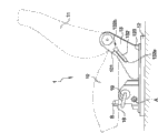
Fig. 2 and 3 is respectively the lateral plan of the seat shown in Figure 1 that is in lowering position and raised position;
Fig. 4 is the block diagram that seat shown in Figure 1 is observed from another angle;
Fig. 5 is the part sectional view of edge line V-V as shown in Figure 1;
Fig. 6 is similar to view Fig. 4, second embodiment of the invention.
The specific embodiment
Seat frame also comprises two supporting members 14,15 that are attached to respectively on one of removable section bar 120.The preceding transverse member 16 that adopts the equalizing bar form is installed, it can be pivoted with respect to supporting member 14,15 between as shown in Figure 2 lowering position and raised position as shown in Figure 3.
In addition, chair dish 10 comprise by metal sheet make, in order to form a kind of chair dish framework 100 that holds the chair bucket of chair plate mat, described chair plate mat constitutes in a conventional manner and is not shown in the drawings.Forwardly locate, chair dish 10 comprises horizontal half-cylindrical recess 103, and the main shaft 160 of preceding transverse member 16 is housed in the recess 103 and is installed into and can pivot.Main shaft 160 remains in the recess 103 by two cover pieces 104, and cover piece 104 appends on the chair dish framework 100 and it is shaped as half round post with recess 103 complementations.At the rear portion, the chair dish is included in the cross bar 102 of place, end rest pin 101.Pin 101 for example is attached on the cross bar 102 by being threaded, and it passes slit 132 from the seat outside and is placed on the throne.This is threaded does not need speciality tool and can be compatible mutually with punctualization fitting operation.This operation that simply is threaded can also be carried out after equipment chair dish again.
The regulating mechanism 19 of the position of transverse member 16 before seat 1 also is included in and regulates between lowering position and the raised position and keep.Regulating mechanism 19 is attached on one of supporting member 14, and comprise and be attached to before band tooth quadrntnt 161 gears in meshs 190 on the transverse member 16, this point can specifically be observed in Fig. 4.Mechanism 19 is designed so that the rotation that it can pinion 190, and the position that when not having control action to act in the mechanism 19, can keep gear 190.Shown mechanism 19 has manual control piece, but also can use automatically controlled product.
Seat also comprises two springs 18, and spring 18 acts between the cross bar 102 of the back transverse member 131 of support portion 13 and chair dish 10, is tending towards guiding chair dish 10 into rear.
When current transverse member 16 was in lowering position, the axis B of main shaft was positioned at the place ahead of the pivot axis A of transverse member 16.Sell 101 leading section 132a places that are positioned at slit 132.
When seat occupant acts in the mechanism 19 and during along the transverse member of direction pivot shown in the arrow F1, preceding transverse member 16 so that the axis B of main shaft upwards and the mode that moves backward be orientated towards raised position.Main shaft 160 is upwards and to the leading portion of rear drive chair dish 10, thus make pin 101 in slit 132 equally also upwards and slide backward.The participation of spring 18 helps this and moves.
Described moving can be continued up to arriving at raised position, in described raised position, and the place, vertical top of the pivot axis A of transverse member 16 before the axis B of main shaft roughly is positioned at.On this position, pin 101 is positioned at 132b place, the other end,, is positioned at the highest and aftermost position of slit 132 that is.Thus, chair dish 10 has carried out upwards and integral body backward moves, and its angle of inclination does not significantly change.
Seat occupant can be controlled oppositely moving, and can make on the mobile any midway location that stops between lowering position and the raised position.
In second embodiment of the present invention, preceding transverse member 16 ' is not made by single pipe fitting, but main shaft 160 ' is connected on the pivotal part 162, as shown in Figure 6 by the flange 161 ' that includes band tooth quadrntnt.The operation of second embodiment is identical with the operation of first embodiment.
Claims (10)
1. automotive seat comprise and are intended to be attached to the seat frame on the vehicle floor and are mounted to and can it is characterized in that by chair dish connecting device (17,16) with respect to the chair dish (10) that described seat frame moves:
One described chair dish connecting device comprises the preceding transverse member that adopts the equalizing bar form, (16), transverse member is mounted between lowering position and raised position along pivot axis before described, (A) pivot with respect to described seat frame, and transverse member comprises having the pivot axis of being parallel to before described, (A) axis, (B) main shaft, (160), transverse member before described, when (16) being in described lowering position, described main shaft, (160) axis, (B) be positioned at described preceding transverse member, (16) pivot axis, (A) the place ahead, and be
One described chair dish connecting device further comprises at least one sliding-pivot spare (17), described sliding-pivot spare (17) is arranged in the rear portion of described chair dish (10), and be arranged to along making progress and the translation direction slip of orientation backward, make transverse member before described (16) when described lowering position advances to described raised position, with upwards and translation mode backward realize that the integral body of described chair dish moves.
2. seat according to claim 1, wherein, transverse member (16) when being in raised position before described, the axis of described main shaft (B) be positioned at described before the vertical top of pivot axis (A) of transverse member (16).
3. seat according to claim 1, wherein, described preceding transverse member (16) comprising: the pipe fitting that forms described main shaft (160); With fixed form described main shaft (160) is connected to the arm (161 ') of pivotal part (162), make described before transverse member (16) can pivot with respect to described seat frame.
4. seat according to claim 1 is characterized in that, described seat is included in the regulating mechanism (19) of regulating and keep the position of described preceding transverse member (16) between described lowering position and the described raised position.
5. seat according to claim 4, wherein, described mechanism (19) comprises and band tooth quadrntnt (161) mating gear (190) that is attached on the described preceding transverse member (16).
6. seat according to claim 3, wherein, described arm is a flange (161 '), and described seat is included in the regulating mechanism (19) of regulating and keep the position of described preceding transverse member (16) between described lowering position and the described raised position, and described mechanism (19) comprises and the band tooth quadrntnt mating gear (190) that is formed in the described flange (161 ').
7. seat according to claim 1, wherein, described chair dish (10) comprising: by the chair dish framework (100) that metal sheet is made, described chair dish framework (100) comprises that the recess (103) that wherein is installed in described main shaft (106) and at least one remain on cover piece (104) in the described recess (103) with described main shaft (160).
8. seat according to claim 1, wherein, described sliding-pivot spare (17) comprises that being attached to described chair dish (10) goes up and be mounted to and slide in the slit (132) at described seat frame and the pin (101) of pivot.
9. seat according to claim 1, wherein, described seat frame comprises: two removable section bars (120) of guaranteeing slide (12) that the position of described seat is vertically regulated; Two supporting members (14,15) that are attached to respectively on one of described removable section bar (120), described preceding transverse member (16) is mounted to respect to described supporting member (14,15) and pivots; And the back support portion (13) of supporting described sliding-pivot spare (17), described support portion, back (13) is attached on described two removable section bars (120).
10. seat according to claim 1 is characterized in that, described seat comprises that at least one acts between described seat frame and the described chair dish (10), is tending towards making described preceding transverse member (16) to enter the spring (18) of described raised position.
Applications Claiming Priority (2)
| Application Number | Priority Date | Filing Date | Title |
|---|---|---|---|
| FR0654955A FR2908699B1 (en) | 2006-11-17 | 2006-11-17 | MOTOR VEHICLE SEAT WITH ADJUSTABLE SEAT |
| FR0654955 | 2006-11-17 |
Publications (2)
| Publication Number | Publication Date |
|---|---|
| CN101181879A CN101181879A (en) | 2008-05-21 |
| CN100592993C true CN100592993C (en) | 2010-03-03 |
Family
ID=38267507
Family Applications (1)
| Application Number | Title | Priority Date | Filing Date |
|---|---|---|---|
| CN200710170385A Active CN100592993C (en) | 2006-11-17 | 2007-11-15 | Motor vehicle seat including adjustable chair seat |
Country Status (4)
| Country | Link |
|---|---|
| CN (1) | CN100592993C (en) |
| BR (1) | BRPI0704019A (en) |
| FR (1) | FR2908699B1 (en) |
| RU (1) | RU2007142327A (en) |
Cited By (1)
| Publication number | Priority date | Publication date | Assignee | Title |
|---|---|---|---|---|
| CN102985285A (en) * | 2010-05-19 | 2013-03-20 | C.劳勃.汉默斯坦两合有限公司 | Adjustment device for motor vehicle seats, in particular height adjustment devices |
Families Citing this family (4)
| Publication number | Priority date | Publication date | Assignee | Title |
|---|---|---|---|---|
| DE102009052111B4 (en) * | 2009-11-05 | 2012-05-16 | Johnson Controls Gmbh | Seat cushion tilt adjustment |
| US9821688B2 (en) * | 2014-10-02 | 2017-11-21 | Ford Global Technologies, Llc | Rear seat cushion with H-point articulation |
| CN113771705B (en) * | 2021-09-22 | 2022-06-17 | 麦格纳座椅研发(重庆)有限公司 | Automobile seat capable of adjusting comfortable posture |
| CN113650533B (en) * | 2021-09-22 | 2022-07-01 | 麦格纳座椅研发(重庆)有限公司 | Automobile seat achieving comfort |
Family Cites Families (3)
| Publication number | Priority date | Publication date | Assignee | Title |
|---|---|---|---|---|
| GB2224198A (en) * | 1988-10-26 | 1990-05-02 | Ford Motor Co | Seat positioning mechanism |
| GB2373435B (en) | 2001-03-19 | 2004-09-22 | Autoliv Dev | Improvements in or relating to a support arrangement for a vehicle seat |
| JP4032827B2 (en) * | 2002-05-24 | 2008-01-16 | トヨタ紡織株式会社 | Seat vertical device |
-
2006
- 2006-11-17 FR FR0654955A patent/FR2908699B1/en active Active
-
2007
- 2007-11-13 BR BRPI0704019-9A patent/BRPI0704019A/en not_active Application Discontinuation
- 2007-11-15 CN CN200710170385A patent/CN100592993C/en active Active
- 2007-11-16 RU RU2007142327/11A patent/RU2007142327A/en not_active Application Discontinuation
Cited By (1)
| Publication number | Priority date | Publication date | Assignee | Title |
|---|---|---|---|---|
| CN102985285A (en) * | 2010-05-19 | 2013-03-20 | C.劳勃.汉默斯坦两合有限公司 | Adjustment device for motor vehicle seats, in particular height adjustment devices |
Also Published As
| Publication number | Publication date |
|---|---|
| FR2908699A1 (en) | 2008-05-23 |
| BRPI0704019A (en) | 2008-07-01 |
| FR2908699B1 (en) | 2009-01-16 |
| CN101181879A (en) | 2008-05-21 |
| RU2007142327A (en) | 2009-05-27 |
Similar Documents
| Publication | Publication Date | Title |
|---|---|---|
| US20110163574A1 (en) | Automatically Adjustable Head Restraint | |
| US8141952B2 (en) | Adjustable bolster assembly | |
| EP1815769B1 (en) | Cushion plate with pressure regulating mechanism of vehicle seat | |
| US6789846B2 (en) | Vehicle seat having a movable head restraint | |
| CN100592993C (en) | Motor vehicle seat including adjustable chair seat | |
| CN105480123A (en) | Torsion bar upper seatback support assembly | |
| US9315130B2 (en) | Articulating head restraint | |
| US9809133B2 (en) | Reclining seat assembly | |
| KR20150005657A (en) | Seat inclination adjustment mechanism, vehicle seat, and method for mounting said vehicle seat | |
| WO2006127131A3 (en) | Recliner spinal traction device | |
| US20080217971A1 (en) | Active Head Restraint | |
| KR101725414B1 (en) | Leg rest apparatus for vehicle seat | |
| WO2004094180A1 (en) | Height adjusting device for car seat | |
| CN105480124A (en) | Manual upper seatback support | |
| KR101724915B1 (en) | Apparatus for reclining rear seat for vehicle | |
| US11273736B2 (en) | Seat assemblies having tip up and tilt seat cushion frames | |
| US7922230B2 (en) | Vehicle seat with a seat tilt adjustment | |
| EP2855196B1 (en) | Fold and kneel seat wtih rearward folding motion | |
| CN115303138B (en) | Automobile seat and automobile with same | |
| CN112297978B (en) | Headrest arrangement and vehicle seat comprising such a headrest arrangement | |
| WO2022109180A1 (en) | Seat assembly with zero-gravity position | |
| KR101252498B1 (en) | Apparatus for passenger convenience in a rear seat | |
| US20240217397A1 (en) | Seat assembly | |
| EP4311721A1 (en) | Movement device of a seat for a vehicle | |
| CN118438930A (en) | Vehicle seat structure and vehicle seat |
Legal Events
| Date | Code | Title | Description |
|---|---|---|---|
| C06 | Publication | ||
| PB01 | Publication | ||
| C10 | Entry into substantive examination | ||
| SE01 | Entry into force of request for substantive examination | ||
| C14 | Grant of patent or utility model | ||
| GR01 | Patent grant |