CN100586414C - Reservoir device with inclined needle - Google Patents
Reservoir device with inclined needle Download PDFInfo
- Publication number
- CN100586414C CN100586414C CN200480031195A CN200480031195A CN100586414C CN 100586414 C CN100586414 C CN 100586414C CN 200480031195 A CN200480031195 A CN 200480031195A CN 200480031195 A CN200480031195 A CN 200480031195A CN 100586414 C CN100586414 C CN 100586414C
- Authority
- CN
- China
- Prior art keywords
- reservoir
- flexible reservoir
- pin
- flexible
- outlet
- Prior art date
- Legal status (The legal status is an assumption and is not a legal conclusion. Google has not performed a legal analysis and makes no representation as to the accuracy of the status listed.)
- Expired - Fee Related
Links
Images


Classifications
-
- A—HUMAN NECESSITIES
- A61—MEDICAL OR VETERINARY SCIENCE; HYGIENE
- A61M—DEVICES FOR INTRODUCING MEDIA INTO, OR ONTO, THE BODY; DEVICES FOR TRANSDUCING BODY MEDIA OR FOR TAKING MEDIA FROM THE BODY; DEVICES FOR PRODUCING OR ENDING SLEEP OR STUPOR
- A61M5/00—Devices for bringing media into the body in a subcutaneous, intra-vascular or intramuscular way; Accessories therefor, e.g. filling or cleaning devices, arm-rests
- A61M5/14—Infusion devices, e.g. infusing by gravity; Blood infusion; Accessories therefor
- A61M5/142—Pressure infusion, e.g. using pumps
- A61M5/14244—Pressure infusion, e.g. using pumps adapted to be carried by the patient, e.g. portable on the body
- A61M5/14248—Pressure infusion, e.g. using pumps adapted to be carried by the patient, e.g. portable on the body of the skin patch type
-
- A—HUMAN NECESSITIES
- A61—MEDICAL OR VETERINARY SCIENCE; HYGIENE
- A61J—CONTAINERS SPECIALLY ADAPTED FOR MEDICAL OR PHARMACEUTICAL PURPOSES; DEVICES OR METHODS SPECIALLY ADAPTED FOR BRINGING PHARMACEUTICAL PRODUCTS INTO PARTICULAR PHYSICAL OR ADMINISTERING FORMS; DEVICES FOR ADMINISTERING FOOD OR MEDICINES ORALLY; BABY COMFORTERS; DEVICES FOR RECEIVING SPITTLE
- A61J1/00—Containers specially adapted for medical or pharmaceutical purposes
- A61J1/14—Details; Accessories therefor
- A61J1/1406—Septums, pierceable membranes
-
- A—HUMAN NECESSITIES
- A61—MEDICAL OR VETERINARY SCIENCE; HYGIENE
- A61M—DEVICES FOR INTRODUCING MEDIA INTO, OR ONTO, THE BODY; DEVICES FOR TRANSDUCING BODY MEDIA OR FOR TAKING MEDIA FROM THE BODY; DEVICES FOR PRODUCING OR ENDING SLEEP OR STUPOR
- A61M5/00—Devices for bringing media into the body in a subcutaneous, intra-vascular or intramuscular way; Accessories therefor, e.g. filling or cleaning devices, arm-rests
- A61M5/14—Infusion devices, e.g. infusing by gravity; Blood infusion; Accessories therefor
- A61M5/142—Pressure infusion, e.g. using pumps
- A61M5/14244—Pressure infusion, e.g. using pumps adapted to be carried by the patient, e.g. portable on the body
- A61M2005/14268—Pressure infusion, e.g. using pumps adapted to be carried by the patient, e.g. portable on the body with a reusable and a disposable component
-
- A—HUMAN NECESSITIES
- A61—MEDICAL OR VETERINARY SCIENCE; HYGIENE
- A61M—DEVICES FOR INTRODUCING MEDIA INTO, OR ONTO, THE BODY; DEVICES FOR TRANSDUCING BODY MEDIA OR FOR TAKING MEDIA FROM THE BODY; DEVICES FOR PRODUCING OR ENDING SLEEP OR STUPOR
- A61M5/00—Devices for bringing media into the body in a subcutaneous, intra-vascular or intramuscular way; Accessories therefor, e.g. filling or cleaning devices, arm-rests
- A61M5/14—Infusion devices, e.g. infusing by gravity; Blood infusion; Accessories therefor
- A61M5/142—Pressure infusion, e.g. using pumps
- A61M5/14212—Pumping with an aspiration and an expulsion action
- A61M5/14216—Reciprocating piston type
-
- A—HUMAN NECESSITIES
- A61—MEDICAL OR VETERINARY SCIENCE; HYGIENE
- A61M—DEVICES FOR INTRODUCING MEDIA INTO, OR ONTO, THE BODY; DEVICES FOR TRANSDUCING BODY MEDIA OR FOR TAKING MEDIA FROM THE BODY; DEVICES FOR PRODUCING OR ENDING SLEEP OR STUPOR
- A61M5/00—Devices for bringing media into the body in a subcutaneous, intra-vascular or intramuscular way; Accessories therefor, e.g. filling or cleaning devices, arm-rests
- A61M5/14—Infusion devices, e.g. infusing by gravity; Blood infusion; Accessories therefor
- A61M5/142—Pressure infusion, e.g. using pumps
- A61M5/14212—Pumping with an aspiration and an expulsion action
- A61M5/14224—Diaphragm type
Abstract
The present invention provides an apparatus comprising a flexible reservoir comprising first and second flexible foil portions sealed together to form an enclosed cavity adapted to contain a fluid, the reservoir having a pouch-like configuration defining a general plane, a needle-penetratable outlet being arranged on a portion of the reservoir which is inclined relative to the general plane. The apparatus further comprises a needle having a generally straight inlet portion and an outlet, the inlet being adapted to be arranged in fluid communication with the reservoir, wherein the needle and the reservoir are arranged moveable relative to each from an initial position in which there is no fluid communication therebetween and a connected position in which the needle inlet is arranged in fluid communication with the reservoir through the reservoir outlet, and wherein the needle in the connected position penetrates the reservoir outlet substantially in parallel with the general plane.
Description
Technical field
Present invention relates in general to a kind of device that comprises the reservoir that is used for storing fluid, described reservoir comprises outlet, and this outlet permission fluid guiding elements for example spike member enters reservoir inside.Especially, this reservoir can be designed to hold medical use liquid material particularly for example medicine, medicinal liquid, transfusion, injection, dialysis solution, infusion liquid, chemistry and liquid, human blood and composition thereof nutrition, or the like.This reservoir also can be used to other purpose, for example, is used to store the calibration solution that analytical equipment is used.
Background technology
In the present disclosure of the invention, be primarily aimed at the top listed liquid that is the medical use liquid form, yet this is an exemplary application of the present invention.
Medical use liquid is accommodated in the reservoir (for example container, bag or bottle) usually, utilizes hollow needle to carry out the access medical use liquid to reservoir, and described pin penetrates the special-purpose Connection Element (or inlet device) of reservoir usually, thereby is communicated with the inner fluid that forms of reservoir.The pin type access both can be used for extracting liquid from reservoir, can be used for again to reservoir supply liquid.For example, when preparing such fluid, be that this fluid will be when given reservoir be put in the patient body, normally active drug is fed in the reservoir that is filled with conveyance fluid of sealing in advance, described conveyance fluid is sodium chloride solution or glucose solution normally, then, by intravenous (IV) input equipment the medicine of dilution is supplied with patient.For this application, reservoir can be provided with the single Connection Element that is applicable to two purposes, or, reservoir can comprise two Connection Elements, these two Connection Elements are respectively applied for purpose separately, for example, are used for bigger input equipment and go out lancet and less medicine entry needle.Connection Element can so that opening is provided, just can be inserted this opening to pin subsequently by manual unlocking, or, utilize the pin of point to penetrate Connection Element, Connection Element can be self-sealed, for example, after pin was withdrawn from, Connection Element can seal reservoir.
If reservoir is a glass, so, Connection Element just can be an individual component, and this individual component is installed on the described glass reservoir by dedicated mode, yet, for the plastics reservoir, the common and integral body of reservoir formation of Connection Element.One of doctor's week plastics reservoir that is widely used most is flexible transfusion bag, and the bottom of this flexibility transfusion bag has the transparent Connection Element of one or more pins.This bag is made by flexible foil usually, and these flexible foil are connected and form the inner space.According to the actual configuration of bag, Connection Element can be set on the surface portion of paillon foil, also can be configured to the marginal portion corresponding to reservoir.For latter's type, Connection Element is set up usually and is fixed on by welding in the position between interconnective two paillon foils.
For above-mentioned two kinds of structures, the self sealss element is being carried by tube element usually, and this tube element is connected on the bag in any mode in the above-mentioned dual mode.For example, U.S. Pat 4,362 discloses a kind of transfusion bag in 458, and wherein, the tubular nozzle element is connected with transfusion bag corresponding to a Free Surface of transfusion bag, and a self sealss rubber element is installed on this nozzle.
For some liquid, the medicine of some type for example, the elastomeric material of wishing to be generally used for to make potted component does not contact with medicine.In order to address this problem, European patent application EP 0364783 discloses a kind of like this medicine bottle, and this medicine bottle has an outer seal component, and this outer seal component is fixed into the position by independent cap member, and independent cap member is connected on the outer surface of medicine bottle.
Above-mentioned reservoir is quite big, holds 100-1000ml liquid usually, yet, can also adopt much smaller volume by the reservoir that penetrates the pin access.For example, some calibration solution of the analytical equipment that is used to calibrate is accommodated in the reservoir of little pocket type, and this pouch formula reservoir only holds several milliliters.If adopt correct design, so, these little reservoirs also can be used to medicament purpose.
Summary of the invention
Consider above-mentioned reservoir and device, an object of the present invention is to provide a kind of like this device, this device comprises reservoir, and this reservoir has outlet, and this device can be used effectively.Another object of the present invention provides a kind of like this reservoir, the easy to use and safety of this reservoir, and it is applicable to various uses.Another object of the present invention provides a kind of like this reservoir, and this reservoir can be used for various liquid.By disclosure of the present invention and to the description of exemplary embodiment, just can more be expressly understood other purpose of the present invention and advantage.
In the present disclosure of the invention, some embodiments of the present invention and some aspects will be described, one or more in the above-mentioned purpose can realize for these embodiment and these aspects, or these embodiment and these aspects can realize that those are from following disclosure and to purpose that can be clear and definite the description of exemplary embodiment.
More particularly, in a first aspect of the present invention, a kind of device is provided, this device comprises flexible reservoir, this reservoir limits a chamber, is used to hold fluid, and this reservoir has bag shaped structure, it limits a general plane, and the transparent outlet of pin is set on the part with respect to described general plane inclination of reservoir.In fact, outlet must be suitable for providing sealing around pin, so that avoid any material to leak.This device also includes pin, this needle set has roughly straight intake section and outlet, inlet is suitable for being configured to form fluid with reservoir and is communicated with, and wherein, pin and reservoir are configured to relatively move from an initial position and a link position, at initial position, do not have fluid to be communicated with between pin and the reservoir, at link position, the pin inlet is communicated with by reservoir export mixes fluid with reservoir, wherein, the pin that is in link position is arranged essentially parallel to described general plane and penetrates the reservoir outlet.
Term " is suitable for holding " and is defined as, and reservoir of the present invention can be provided with the state of sky, so that carry out filling subsequently, or, during making reservoir, just filled reservoir.
Can be welded together at its periphery four edges of square reservoir (for example) by two independent foil elements for example and form reservoir, or, by being welded together at remaining peripheral part three edges of square reservoir (for example), folding paper tinsel forms reservoir, or, form reservoir by the paper tinsel pipe that is welded together at two ends.Therefore, for typical bag or scrotiform reservoir, weld part (for example two opposed weld parts) can be used to limit the general plane of reservoir, still, also can be arranged on other position to weld part.When reservoir was filled, reservoir can expand usually, thereby one or more convex surface are provided, and the convex surface except " top " zone will be configured to tilt with respect to general plane.For a part of paper tinsel surface that more tilts, surface than the reservoir of " intrinsic " structure is provided, can make the remainder deflection of the part of reservoir with respect to reservoir, for example, along a line bending, this helps pin to be inserted in the reservoir.
Outlet can be configured to any suitable structure, so that allow the inner fluid that forms of pin and reservoir to be communicated with.Can allow pin to puncture if form the foil material of reservoir, so, just need not to be provided with additional element, still, in most of the cases, additional outlet element must be set in the mode of not leaking.
For example, reservoir outlet element can be the diaphragm element form, and this diaphragm element is formed by the transparent self-sealing material of pin described above, and advantageously, barrier film connects by welding.Except those formed the part of outlet, barrier film can also cover the some parts of reservoir, and for example, barrier film can be set on the circular edge part of reservoir, thereby also just covered the part with respect to described general plane perpendicular positioning of reservoir.As mentioned above, according to the fluid that is contained in the reservoir, the wall of reservoir can comprise one or more layers.
Although term " self sealss " is clearly to those skilled in the art, should be noted that for given barrier film it can not be considered to an absolute terms, it depends on the purposes of given reservoir.For example, a given barrier film is configured to self-packing, and it is connected with the pin of given tolerance (being diameter) scope, and has a given configuration design for the end of point.Therefore, for the barrier film of the relative thin that is applicable to corresponding fine needle, when being punctured by bigger pin, this barrier film possibility just can not self sealss.In addition, if reservoir is forced into and is higher than predeterminedly when intrinsic pressure, the barrier film that is punctured may leak.
In some preferred embodiments, described inclination angle preferably less than 30 degree, more preferably is less than 15 degree (the parallel zero degree that is defined as) less than 45 degree.By introducing described pin with an angle of inclination, need not the needle penetration reservoir with outlet element opposite part, reservoir may subside fully or part is subsided.
If be contained in the reservoir fluid (liquid or gas) to around wall do not have a particular characteristic requirement (for example, aspect evaporation, leakage or chemical inertness), so, first paper tinsel part can be made by monolayer material, or reservoir is made by homogenous material generally.If fluid has the requirement of particular characteristic to reservoir, so, reservoir can be provided with outer surface and inner surface, and described outer surface is made by first material generally, and described inner surface is made by second material generally.The wall portion that provides or comprise inlet can have ad hoc structure (for example, allowing needle penetration), and the remainder of reservoir wall has different performances.
The paper tinsel element can be the composite laminated body of pantostrat, and pantostrat comprises skin and internal layer.This just allows outer surface optimised, so that be connected with diaphragm element, for the fluid that is received, inner surface can be optimised at the reservoir aspect of performance.Any layered product of being mentioned among the present invention can be traditional layered product, common extrudate or extrusion laminates.The wall that constitutes reservoir can be made by the layered product of homogenous material or single type, or different materials or layered product can be used for the different wall portion of reservoir.
The paper tinsel element can comprise an intermediate layer, but internal layer make by welding material, but this welding material allows the periphery by the corresponding bag of welding, and the paper tinsel element can partly be sealed at least.If skin only provides membranous installation surface, so, the part that " centre " layer can be reservoir provides outer.In order to allow by the visible liquid that holds of reservoir wall energy, at least a portion of reservoir wall can be made by transparent or semitransparent material.
As the outside reservoir wall of a part can be optimised so that connect the barrier film by welding, barrier film is installed the surface also can be optimised.For example, barrier film can be a layered product, and this layered product comprises two-layer or more multi-layered, and the D score layer provides installs the surface.Barrier film can be soldered on the reservoir corresponding to the surface of whole erection basically, yet barrier film also can utilize one or more (concentric) peripheral weld part soldered.
Except sealing property, barrier film can also be configured to provide additional performance.For example, a membranous part or whole barrier film can be configured to can be crooked with the part of the reservoir that it was installed to, and this just allows barrier film to be bent during manufacture, also can be bent during use.In order to allow this bending, barrier film can be the form of the element of relative thin, or it can comprise the part of relative thin.In addition, when barrier film was arranged on the reservoir by " open ground ", except fluid connection described above can be provided, it can also carry out access for other purpose.
In one exemplary embodiment, this device also includes the expulsion assembly, and this expulsion assembly is suitable for the fluid (for example medicine) that is contained in the reservoir is discharged by the outlet of reservoir.The expulsion assembly can be used for driving or aspirating medicine from reservoir.In the later case, the expulsion assembly can be the form of a suction pump, and this suction pump has: inlet; Outlet; And the internal circulation path between entrance and exit, inlet is suitable for being configured to form fluid by pin and reservoir and is communicated with.
Reservoir and expulsion assembly can be configured to and can relatively move, or, they both can be by relative fixed, provide fluid to be communicated with by fluid coupling movably, advantageously, described fluid coupling is configured to expel the part of assembly, thereby as an inlet.More particularly, under original state, inside at the expulsion assembly can be provided with fluid coupling, fluid coupling includes entrance and exit, wherein, fluid coupling is configured to and can and enters mode of operation from the original state operation, in mode of operation, between the inside of the inside of reservoir and expulsion assembly, form fluid and be communicated with, and the outlet of fluid coupling is set in the circulation path of expulsion assembly by fluid coupling.
This device can be the form that can be installed in the pumping unit on the skin, and it also comprises: the transdermal equipment that is suitable for penetrating curee's skin; The surface is installed, is suitable for being applied on curee's the skin, wherein, reservoir comprises fluid medicine, and in user mode, the expulsion assembly is used to described medicine is evicted out of described reservoir, and enters curee's skin by transdermal equipment.Transdermal equipment can be the form of the hollow infusion needle of point, the combination of the pin pick off of microneedle arrays, point or quite softish blunt intubate itself or can provide the transdermal equipment of point with the pick off of slightly pointed contact pin, contact pin can be withdrawn after the blunt part of inserting transdermal equipment.Advantageously, for the contact pin that is hard draw point usually, intubate is soft and flexible.In disclosure of the present invention and exemplary embodiment, be primarily aimed at the transdermal equipment that is the transfusion needle form.Reservoir can offer user to be filled good form in advance, also can be filled (with filling) by user again.
The present invention also provides a kind of method that connects flexible reservoir and pin, comprise step: provide flexible reservoir, this flexible reservoir has bag shaped structure, this bag shaped structure limits a general plane, this reservoir comprises the transparent outlet of pin, and the transparent outlet of this pin is set at being on the part of inclination with respect to described general plane of reservoir; Pin is provided, and this needle set has roughly straight intake section; Make pin be arranged essentially parallel to described general plane and insert and to penetrate mouth, be communicated with thereby between pin and reservoir, form fluid.
As mentioned above, " exposing " membrane configuration can be used to provide additional function to reservoir.Correspondingly, in another aspect of the present invention, provide a kind of device, this device includes shell, is suitable for holding fluidic flexible reservoir, and comprise diaphragm element, this diaphragm element is made by the transparent self-sealing material of pin, and at least a portion of flexible reservoir is set up in the enclosure, and installing device, this installing device is set up in the enclosure or by shell and forms, wherein, installing device is engaging diaphragm element, thereby with respect to installing device flexible reservoir is installed.In this way, just can between reservoir and installing device, form firm fixing, and can not disturb the overall flex of reservoir, for example, except outlet/installing device, whole flexible reservoir can be configured to can freely move with respect to shell, and this just allows the reservoir can be by the emptying of high level ground.Usually, utilize the reservoir that is provided with in the enclosure to close shell, yet in principle, shell can open wide, in this case, shell plays the effect of supporting construction, and in the context of the present invention, the term shell has comprised supporting member.
In some exemplary embodiments, above-mentioned mounting structure can be used in combination with expulsion assembly and transdermal equipment, so that aforesaid conveying equipment is provided.
As mentioned above, provide a kind of and included membranous reservoir, and described barrier film is combined with the additional member that is used to install and/or is connected this reservoir.Therefore, corresponding to another aspect of the present invention, provide reservoir itself, this reservoir is suitable for fluid containment in the chamber that is made of wall, and this reservoir comprises the first wall part, and this first wall part is made by the transparent material of pin, wherein, this wall part comprises that outside first installs the surface.This reservoir also comprises diaphragm element (also being known as barrier film hereinafter), this diaphragm element is made by the transparent self-sealing material of pin, diaphragm element comprises that second installs the surface, wherein, corresponding to second the surface is installed, by two surface soldered mode together, this diaphragm element is installed in first installs on the surface.First setting that the material on surface is installed is only laid correspondingly with membranous, or first material that the surface is installed can cover whole outer surface or a part of outer surface of reservoir.This reservoir is hard relatively reservoir (for example Chui Zhi bottle), also can be flexible reservoir, for example aforesaid traditional intravenous (IV) input bag.
Although barrier film can be installed separately,, it is desirable to, additional installing device is provided, so that can the access arrangement such as pipe fitting be connected with reservoir, described reservoir for example is a known vein input bag described above.For example, can for example connect around being connected to barrier film from the outstanding tubular configured joint in reservoir surface along periphery.In this way, these two parts can be connected independently of each other, and need not barrier film is installed on the described joint, and still, mode is easily, during welding process, these two parts is connected on the reservoir simultaneously.
Barrier film can also be manufactured into and be used for other purpose.For example, if reservoir is the flexible reservoir form, this flexible reservoir is suitable for being installed in the medicament delivery device described above, so, and during installation procedure, as barrier film can be used as connection device between reservoir and the conveying equipment, barrier film just can be used to handle described reservoir, and for example, diaphragm element can be soldered on the conveying equipment, or diaphragm element and conveying equipment can be provided with the jointer of cooperation.
The material of the barrier film of different aspect and formation reservoir can be selected according to the foregoing description and their purposes according to the present invention.For example, provide first wall part that the surface is installed to make or comprise following material by following material: polyethylene (PE), polypropylene (PP), directed polypropylene (OPP), non-crystalline polyester (PET), directed non-crystalline polyester (OPET), polyamide (PA) or directed polyamide (OPA).Forming second membrane portions that the surface is installed can be made by thermoplastic elastic (TPE) material, is for example made by the thermoplastic material of lipophilic group or the thermoplastic vulcanizate of lipophilic group or their mixture.More particularly, TPE can be the thermoplastic vulcanizate (for example the registered trade mark of selling on the market is the rubber of Trefsin) that is made of the brombutyl rubber (bromo-butyle) that is polypropylene matrix (polypropylene matrix), the thermoplastic vulcanizate (for example the registered trade mark of selling on the market is the rubber of Santoprene) that constitutes by the EPDM rubber that is polypropylene matrix or based on (SEBS) elastomer of copolymer (for example the registered trade mark of selling on the market is the elastomer of Kraiburg) of butylbenzene ethylene ethylene butene (styreneethylene butylenes styrene).In addition, also can use TPU, TPE-A or TPE-E.
Here, used term " medicine " comprises any flowable medicine that contains medicine, it can through conveying equipment for example hollow needle be transferred in a controlled manner, this medicine for example is liquid, solution, gel or finely divided suspension.Representational medicine comprises these medicaments, nutrient formulation that for example peptide, protein, hormone, biology, mode obtained or active medicament, the medicament based on hormone and gene, solid (being assigned with) or liquid form and other materials.In exemplary embodiment of the present invention is described, be primarily aimed at the description of using insulin.Therefore, term " subcutaneous " input comprises any method of carrying out subcutaneous delivery to the curee.
Here, term " insulin " is meant the insulin from any species, for example Iletin II (Lilly), bovine insulin and insulin human, and its salt for example is the reactive derivative and the insulin analog of zinc salt, protamine salt and insulin.Term " reactive derivative of insulin " is the derivant of being mentioned in the general textbook that it has been generally acknowledged that of those skilled in the art, for example, has the insulin of non-existent sub in paternal insulin molecule.Term " insulin analog " is meant such insulin, wherein, one or more amino acid residues (amino acidresidues) exchange mutually with other amino acid residue, and/or from this insulin, one or more amino acid residues are deleted, and/or from this insulin, one or more amino acid residues are promptly made described insulin analog have enough insulin actives by additional conditions.
The material that is used to form reservoir of the present invention or reservoir device can be selected according to purposes.Therefore, can require these materials can satisfy for example physical characteristic requirement of material after sterilization of specific functional requirement, and the chemical requirement of the material after sterilization, the spatter property requirement.Therefore, material can utilize gamma-rays, electron beam, steam or ethylene oxide to carry out disinfection.Material also can be selected according to the one or more requirements in the following requirement, and these requirements are: 1) material must be transparent, 2) material must be resisted the water evaporation well; 3) material must be resisted gas (for example oxygen and carbon dioxide) well; 4) material must be resisted antiseptic (for example phenol and cresol (meta-cresol) partially) well; 5) material must be resisted abnormal smells from the patient (for example antiseptic) well; 6) material must be able to be resisted environmental stress pressure break (stress cracking) (for example, oil, spice); 7) material must be able to be resisted bending and splits; 8) material must have excellent sealing performance (for example, by welding); 9) material handle or must be after sterilization between the storage life can not layering, 10) material store and necessary between the operating period can not be significantly lax, 11) material must not can go out the material (leachable) that the health and safety to patient exerts an influence to drug release; 12) material must have the extractable of very low degree; 13) material must with the compounding pharmaceutical compatibility of being held.Relevant in addition is, material satisfies certain health and safety requirement, preferably satisfies most of or all requirements of being mentioned in the document regulations below, and these document regulations have: 1) European Pharmacopoeia (PH.Eur) 2002 is the 4th edition; 2) American Pharmacopeia (USP) 25; 3) Japanese Pharmacopoeia (JP) XIV; 4) EEC regulations 90/128+ revises " about plastic material and the object that is used for contacting foodstuff "; 5) Federal law regulation (CFR), 21 title food and medicines, 170-190 part; 6) III/9090/90EN.Plastics master package material.Guide is annotated and is shown; 7) industrial directory.Be used to pack container closure system, chemistry, manufacturing and control document (Chemistry, Manufacturing, the andControls Document) .FDA of human medicine and biological preparation, in May, 1999.
About layered product, adopt following definitions: common extrusion molding comprises such process, wherein, in two or more extruders, merge two or more polymeric materials, carry out common extrusion molding by flat nozzle or nozzle system then, be cooled then, so that form the paper tinsel of common extrusion molding.The extrusion molding lamination comprises such process, wherein, applies one or more layers melted material from one or more extruders to a kind of feed of foil material form by flat burner or flat burner system, cools off then to form the extrusion molding laminated foil." routine " lamination comprises such process, wherein, by adding suitable adhesive to paper tinsel the supplying blank of two foil material is bonded together, and then, forms described laminated foil by adding second paper tinsel.Knitting layer is such layer, and it is placed between two polymeric layers, its objective is in order to connect, so that described two layers are bonded together.
Description of drawings
Below with reference to accompanying drawings, further describe exemplary embodiment of the present invention, in these accompanying drawings,
Fig. 1 is the perspective view of a delivery device,
Fig. 2 is the perspective view of another delivery device,
Fig. 3 represents that with Fig. 4 the pump unit is connected with reservoir,
Fig. 5 A is the general illustration of the pump that links to each other with reservoir,
Fig. 5 B is the decomposition view of pump assembly,
Fig. 5 C is the profile of the pump assembly among Fig. 5 B,
Fig. 5 D and Fig. 5 E are the part sectioned views of the pump assembly among Fig. 5 C,
Fig. 6 A is the perspective view of flexible reservoir,
Fig. 6 B is the side view of the reservoir among Fig. 6 A,
Fig. 6 C is the vertical view of the reservoir among Fig. 6 A,
Fig. 7 A is the side view that is inserted with the reservoir of pin,
Fig. 7 B is the perspective view of the reservoir gained when top is seen among Fig. 7 A,
Fig. 7 C is the perspective view of the reservoir gained when the bottom is seen among Fig. 7 A,
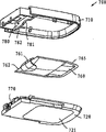
Fig. 8 is the decomposition view of another storage unit.
In these accompanying drawings, same member is mainly represented by same Reference numeral.
The specific embodiment
When following use term " on " and D score, " left side " and " right side ", when " level " and " vertically " or similar relative wording, these wording are only at accompanying drawing, are not at actual operating position.Accompanying drawing just schematically, for this reason, the structure of different component and relative size size just are used to the purpose explained.
In Fig. 1, expressed a delivery device, this device comprises flexible reservoir, it can implement one or more aspect of the present invention.
More particularly, Fig. 1 has expressed the decomposition diagram of a medical treatment device, and this medical treatment device is delivery device 200 forms, and this delivery device 200 comprises: pin unit 210, and this pin unit has pin shell 211; Base members 230, this base members have the bottom surface are installed, and are suitable for being applied on curee's the skin; Isolating reservoir and pump unit 250.In the illustrated embodiment, base members comprises hard relatively top 231, this top 231 is connected to more softish sheet adhesive element 232, but this sheet adhesive element be provided with the grasping band and have the bottom adhesive surface, this bottom adhesive surface provides installs surface itself.In the illustrated embodiment, the pin shell is connected to as on the independent unitary substrate plate, thereby these two elements combination form the pin unit.The transfusion needle 212 of hollow is arranged in the described shell rotationally.
The pin unit comprises that first and second openings, 213,214, the first and second openings can be opened or be covered by the transparent thin film of pin, so that the inside of sealing is provided.Pin comprises the port of export far away of a nearly arrival end and a point.Shell also comprises driving device (not shown) and retracting device (not shown), described driving device is used at retracted mode and stretches out and move described pin between the state, and described retracting device is used for moving described pin between extended position and retracted position.But driving device and retracting device are driven by first and second bands 221,222 of grasping, but first and second bands of grasping be connected on the corresponding device by the slit opening in the shell, can see the groove 223 that is used for first band in the shell among the figure.Second band also links to each other with sheet band 233.Shell is provided with the drivable public jointer of user (malecoupling means) 240, and this public affairs jointer is the hook element form that a pair of elasticity is provided with, and is suitable for matching with female jointer (female coupling means) on the storage unit.Shell also comprises: connecting device 225 is used for forming fluid and is communicated with between pump unit and reservoir (stating content as follows); Communication apparatus 226 is used for driving and stopping banishing device.
Control and driving device can be set on PCB or the crooked printer (flex-print), and this control and driving device comprise: pump driving element 281, and this pump driving element is a lever and piston structure, is driven by coil actuator 282; Microprocessor 283 is used for control pump driving etc.; Contact switch 284, this contact switch matches with communication apparatus 226 on the pin unit; Signal generation device 285 is used to produce audition and/or haptic signal; Energy source 286.
In Fig. 2, expressed a kind of delivery device that has the same general structure with Fig. 1.More particularly, Fig. 2 has expressed a kind of like this delivery device 500, it comprises pin unit 510, this pin unit has housing parts 511 and relative hard base part 530, this base part is connected on the more softish sheet adhesive element 532, this sheet adhesive element has the bottom adhesive surface, is used to provide installation surface itself.Be provided with pin driver element 509 in the enclosure, the pin driver element comprises hollow infusion needle 512, and this transfusion needle is configured to rotatable with respect to substrate plate.
The intake section of pin is corresponding to the pivot center setting, and intake section is being protected by circle tube element 513, unexpectedly by acupuncture so that prevent user.For with drive and withdrawal band 521,522 cooperate mutually, pin driver element 509 comprises: driving device is used in a withdrawal and stretches out mobile described pin between the state; Retracting device is used for moving described pin between the extended and retracted position.The pin unit also comprises public jointer 540 and female jointer (not shown), its be suitable for storage unit on corresponding female jointer and public jointer 555 and connecting device 525 cooperate mutually be communicated with (stating content as follows) so that between pump unit and reservoir, form fluid.
Storage unit 550 includes shell, and this shell is made of upper casing part 551 and lower casing part 553, is provided with reservoir and banishing device in this shell, and described banishing device comprises pump unit 570 and control device 580.Lower casing partly comprises two windows 552,554, so that allow user can check material that reservoir is adorned, a corresponding reservoir indicator (stating content as follows).Reservoir 560 is the form of the pre-flexible foldable bag that fills, this bag is to be formed according to folding corresponding to an edge of reservoir and sealing along its excess-three bar edge by flexible foils, corresponding to the folded edge of circle, be welded with the transparent barrier film 561 of pin on the reservoir.Pump unit in the illustrated embodiment is the membrane pump form, and this pump unit comprises: the pump driving element, and this pump driving element is the form of coil actuator 582, and is operatively coupled on there; Installing device, this installing device is the form of a groove 562, thereby can install and fix described barrier film with respect to the inlet device of pump.The pump unit comprises movably fluid coupling (stating content as follows), is used to penetrate the sloping portion of barrier film 561.
Control device comprises: microprocessor 583 is used for control pump driving etc.; Signal generation device 585 is used to produce audition and/or haptic signal; Energy source 586.Reservoir indicator 582 is connected with control device, is used for indicating the remaining dose of reservoir to user.This indicator can be the form such as the electrochemical strips of used type in the battery.
With reference to Fig. 3 and Fig. 4, the figure invading the exterior shows the another kind of alternative structure of reservoir installing device.Pump unit 670 comprises: substrate plate 675, this substrate plate have first slot part 676; Clamping element 677, this clamping element has second slot part 678, as shown in Figure 4, when clamping element is locked on the substrate plate, these two slot parts are suitable for engaging with the opposed surface of the diaphragm element 661 of reservoir 660, thus make diaphragm element with respect to the fluid coupling 672 that forms pump intake by firm arrangement.As shown in the figure, a membranous part is set on the sloping portion of reservoir.These slot parts can be provided with additional clamping device (for example some projections are not shown in the figures), are used to prevent that barrier film from sliding and be disengaged with installing device.For the purpose of explaining, in Fig. 3, the figure invading the exterior shows fluid coupling and is in extended position, yet, this joint is provided in after the installation and normally before just using, joint can be moved to reservoir and engage, and this will be explained hereinafter in more detail.In the illustrated embodiment, barrier film is clamped between the part and an independent clamping element of pump, yet, also can all for example upper casing and lower casing partly form an integral body with housing parts in these members one or two.
The pump unit also comprises coil actuator 682, and this coil actuator is suitable for engaging the piston element 683,340 (stating content as follows) of membrane pump.In the illustrated embodiment, substrate plate 675 and clamping element 677 are independent members, yet they can partly form an integral body with upper casing part and lower casing respectively.
In Fig. 8, expressed the decomposition view of another kind of storage unit, this storage unit comprises: upper casing element 710; Lower casing element 720, this lower casing element has transparent region 721; Flexible reservoir 760, this flexible reservoir has circular edge part 762, on this circular edge part diaphragm element 761 is installed; Pump assembly 770, this pump assembly has driver; The circuit board (not shown), it is set at the reservoir top, and comprises that some are used for the electronic unit that control pump drives.The upper and lower shell element comprises installing device, and this installing device is the opposed form of rib ridge (ridge) part 780 (cannot see of bottom) up and down, is suitable for engaging and installing in shell described reservoir.Each rib ridge part includes center cutout part 781, and when crust component was assembled, this notch portion was used for engaging with the opposed surface of diaphragm element, thereby in shell reservoir is locked into the position.The degree of locking is determined by being applied to the pressure on the diaphragm element, the elasticity of diaphragm element and the friction between rib ridge and the diaphragm element.In each side of notch portion, the rib ridge part comprises straight part 782, and this straight part can help reservoir is installed in the shell.Straight part can be by closing the initial pre-reservoir that fills, so that help reservoir is locked into the position, yet when reservoir becomes space-variant at ordinary times, this clamping force may reduce.Comparatively speaking, when reservoir becomes empty, be suitable for reservoir is fixed into the position rightly with membranous this joint.Straight part also can be used to clamp reservoir and reservoir is flattened, thereby straight part is as an additional installing device.Additional installing device (not shown) can and clamp described reservoir in other engagement position, for example comes the gripper reservoir along welded edge 765.
With reference to Fig. 5 A, the figure invading the exterior shows the general illustration of the pump that is connected with reservoir, and this pump comprises following general features: fluid connector 391 is used for filling reservoir 390; Relief valve 392; Inlet valve 393 and outlet valve 394; Pump chamber 395, this pump chamber has continuous piston 396; Outlet 397.Arrow among the figure is represented the flow direction between each parts.When piston downward (in the drawings) is mobile, in pump chamber, will form relative negative pressure, this will make inlet valve open, subsequently just from first side the opened suction fluid of reservoir through relief valve.When piston makes progress (in the drawings) when mobile, in pump chambers, just form relative superpressure, this will make inlet valve close, outlet valve and relief valve are opened, thereby fluid just from pump chamber through second effluent of outlet valve and relief valve to outlet.As shown in the figure, in normal running, during sucking and expelling fluid, relief valve allows fluid to pass through, thereby during normal running, relief valve is " passive ".Yet, just in case reservoir pressurized (may take place) for flexible reservoir, elevated pressure in the reservoir will be passed to first side of relief valve by pump chambers, and also be passed to second side of relief valve, in this case, the pressure on first side of relief valve will stop second side to be opened.
In Fig. 5 B, the figure invading the exterior shows the decomposition view of the pump assembly 300 that utilizes the pumping principle described in Fig. 5 A.This pump assembly (also being known as pump hereinafter) is suitable for the reservoir among Fig. 1-4.This pump is a membrane pump, the pumping diaphragm that comprises piston actuated, this pumping diaphragm has the inlet valve and the outlet valve of fluid control, this pumping diaphragm has stratification structure generally, comprise first, second, third element 301,302,303, between these elements, accompany first and second retes 311,312, thereby, the combined formation pump chamber 341 of first and second elements and first rete, first and three element and the combined formation relief valve 345, the second of first rete and three element and combined formation inlet valve 342 of second rete and outlet valve 343 (seeing Fig. 5 C).These retes are fixed into a stacking (stacked) structure by an outer clips 310.Pump also comprises inlet 321 and outlet 322 and connection opening 323, and they are covered with by the film 331,332,333 of correspondence, and under initial aseptic condition, these film phonograph seals the inside of pump.These films can be penetrated or puncture (for example being made of paper) by pin or other element of introducing by given sealing.That outlet also comprises is self-packing, pin is transparent (for example rubber-like material) barrier film 334, this barrier film 334 allow pumps and go out lancet and be connected.Shown in Fig. 5 C, first side through relief valve 345, between inlet 321 (stating content as follows) and inlet valve 342, between inlet valve, pump chamber 345 and outlet valve 343, second side through relief valve forms a fluid path (being represented by dark line) at outlet valve with between exporting 322, and described fluid path is formed in the different layers or is formed between the different layers.Pump also comprises piston 340, is used to drive pumping diaphragm, and this piston is driven by the external driver device (not shown).
Pump also comprises fluid coupling, and this fluid coupling is the form that hollow connects pin 350, and this hollow connects pin and is slidably disposed in the pin chamber 360, and this pin chamber is positioned at the back of connection opening, sees Fig. 5 D.The pin chamber forms by these layers of pump, and comprises inner sealing barrier film 315, and pin is mounted slidably by this barrier film, and barrier film is formed by described first rete.Described pin comprises: the far-end 351 of point; Near-end is provided with pin piston 352 at this near-end; Proximal open 353, it is fluid with far-end and is communicated with, and described pin and piston are mounted slidably with respect to internal diaphragm and chamber.From Fig. 5 D as can be seen, the pin piston that is in initial position is by one or more keyway 359 bypass (bypass) that radially are provided with, these are set is in order to allow to carry out vapor sterilization, when in the pin chamber, moving forward with convenient fluid coupling, air-out, if not like this, air will not be arrested in the inside.
The said pump assembly can be set in the delivery device of type shown in Figure 2.In storage unit being connected to the unitary user mode of pin, the near-end of transfusion needle is introduced into by delivery side of pump sealing and barrier film 334, and Connection Element 525 (see figure 2)s are guided through junctional membrane 333.By this action, connect pin and just shifted onto the activation point shown in Fig. 5 E from its initial position shown in Fig. 5 D, wherein, the transparent barrier film of pin that far-end moves through into membrana oralis 331 and further passes near the reservoir being positioned at so just forms a fluid path through the proximal openings 353 in the pin between reservoir and inlet valve.In this position, between pin piston and pin chamber, form a sealing.
As shown in the figure, when two unit were thrown off, transfusion needle 212 was just withdrawn from from pump discharge, for good and all provided fluid to be communicated with between pump and reservoir and connect pin.
The another kind of structure of the flexible pre-drug reservoir that fills of the conveyer device that is suitable for type shown in Fig. 1 and Fig. 2 is described with reference to Fig. 6 A-6C and 7A-7C below.
Although the reservoir 400 that fills have roughly be convex surface, allow the saturating first surface of cushion, the general plane that this first surface makes pin be roughly parallel to reservoir is inserted, Fig. 7 A-7C has expressed the structure of reservoir, and this structure has been improved pin with the slotting penetrable part 412 of saturating membranous pin of the general plane that is parallel to reservoir.
More particularly, part by making reservoir is with respect to described general plane downwards (for example about 30 degree of deflection shown in Fig. 7 A), the pin 450 of the general plane setting that is parallel to reservoir has been given in the zone 413 of the penetrable part of membranous pin just " offering as a gift ", thereby can easily insert a needle into.Shown in Fig. 7 A, crooked reservoir comprises first " mainly " part 415 and second " less important " part 416, described first " mainly " part 415 corresponds essentially to described general plane setting, described second " less important " part 416 with respect to first " mainly " part along the direction of leaving first surface by deflection, thereby the part 413 of the peripheral part of diaphragm element is set on the second portion of reservoir.In Fig. 7 A-7C, shown reservoir is not used in the device that makes the reservoir bending, and still, this device can be provided by some members around shell.Pin 450 can be the form of top described movably needle adapter.
Example: produce a reservoir that holds the 3ml insulin by two paper tinsel elements in the three-layer type layered product, described three-layer type layered product comprises: the intermediate layer, and this intermediate layer forms (binder course) by PCTFE and the improved polyethylene imine of epoxy (epoxy modified polyethylene imine) co-extruded; One internal layer, it is made of PE; One skin, this skin is made of PP, and is laminated on the PCTFE layer.Before the periphery along two paper tinsel elements welds together these two paper tinsel elements, the diaphragm element that is made of the thermoplastic elastic rubber compound is welded on the outside PP layer, before reservoir is sealed fully, insulin is filled in the reservoir.
In description of preferred embodiments, described different component and device that institute's representation function is provided for different parts above, this description is enough to make understands design of the present invention with those skilled in the art know that.The detailed construction and the specification of different parts are considered to a kind of conventional design that those skilled in the art can obtain according to the content described in the description of the present invention.
Claims (10)
1, a kind of reservoir device (200) with inclined needle comprising:
Flexible reservoir (260,400), described flexible reservoir limit and are used to hold fluidic chamber, and this flexible reservoir has the bag shaped structure that limits a general plane,
The flexible reservoir outlet (261,410) that pin can penetrate, this flexible reservoir outlet are set on the part with respect to described general plane inclination of flexible reservoir,
Pin (350,450), this needle set have roughly straight intake section and pin outlet, and described intake section is suitable for being configured to constitute fluid with flexible reservoir and is communicated with,
Wherein, pin and flexible reservoir can relatively move from initial position to a link position, at described initial position, there is not fluid to be communicated with between pin and the flexible reservoir, at described link position, the pin intake section is communicated with by flexible reservoir export mixes fluid with flexible reservoir
Wherein, flexible reservoir has first surface and opposed second surface, has filled in the fluidic state in flexible reservoir, and described at least first surface has the structure that is convex for flexible reservoir inside and described general plane,
Wherein, in link position, pin is arranged essentially parallel to described general plane and penetrates described flexible reservoir outlet,
Wherein, flexible reservoir comprises first major part and wants part (415 for the second time, 416), described first major part is substantially corresponding to described general plane setting, want the described second time part on away from the direction of the described first surface of described first major part with respect to described general plane by deflection, the flexible reservoir outlet is set to be wanted on the described first surface of part the second time of flexible reservoir.
2, a kind of reservoir device according to claim 1 is characterized in that, flexible reservoir comprises first and second flexible foils parts (404,405), and this first and second flexible foils part is sealed together, thereby forms described chamber.
3, a kind of reservoir device according to claim 2 comprises diaphragm element (410), and this diaphragm element is made by the self-sealing material that pin can penetrate, and this diaphragm element forms the flexible reservoir outlet.
4, a kind of reservoir device according to claim 3 is characterized in that, diaphragm element is installed on the paper tinsel part of flexible reservoir by welding manner.
5, a kind of reservoir device according to claim 3 also comprises:
Shell (251),
Installing device (562,675,677,780), this installing device is set up in the enclosure or by shell and constitutes,
Wherein, installing device engages with diaphragm element, thereby opposite shell is installed flexible reservoir.
6, a kind of reservoir device according to claim 5 is characterized in that, the flexible reservoir except the flexible reservoir outlet device can move freely with respect to shell.
7, a kind of according to the described reservoir device of one of claim 1-6, also comprise expulsion assembly (300,670), this expulsion assembly has inlet (321,672) and the outlet (322) and the expulsion assembly entrance and exit between the internal circulation path, the inlet of expulsion assembly is suitable for being configured to constitute fluid with flexible reservoir via described pin and is communicated with, and the expulsion assembly is suitable for expelling the fluid that is contained in the flexible reservoir by the outlet of this expulsion assembly.
8, a kind of reservoir device according to claim 7, wherein, the expulsion assembly comprises needle adapter (350), this needle adapter is as the inlet of expelling assembly and be used as the pin that links to each other with flexible reservoir,
Wherein, needle adapter (350) is set at the inside of the expulsion assembly that is in the original state, fluid coupling comprises inlet (351) and outlet (353), thereby, this needle adapter is configured to be operated into a mode of operation from original state, in mode of operation, between flexible reservoir inside and expulsion component internal, form fluid and be communicated with, and the outlet of needle adapter is set in the circulation path of expulsion assembly by needle adapter.
9, a kind of reservoir device according to claim 7 comprises:
Transdermal equipment (212) is used to sting curee's skin,
Surface (232) is installed, is used to be applied to curee's skin,
Wherein, flexible reservoir comprises fluid medicine, and
In user mode, the expulsion assembly is used to medicine is evicted out of flexible reservoir, and the skin through transdermal equipment and by the curee.
10, a kind of reservoir device according to claim 8 comprises:
Transdermal equipment (212) is used to sting curee's skin,
Surface (232) is installed, is used to be applied to curee's skin,
Wherein, flexible reservoir comprises fluid medicine, and
In user mode, the expulsion assembly is used to medicine is evicted out of flexible reservoir, and the skin through transdermal equipment and by the curee.
Applications Claiming Priority (3)
| Application Number | Priority Date | Filing Date | Title |
|---|---|---|---|
| DKPA200301546 | 2003-10-21 | ||
| DKPA200301546 | 2003-10-21 | ||
| US60/518,837 | 2003-11-10 |
Publications (2)
| Publication Number | Publication Date |
|---|---|
| CN1870961A CN1870961A (en) | 2006-11-29 |
| CN100586414C true CN100586414C (en) | 2010-02-03 |
Family
ID=37444415
Family Applications (1)
| Application Number | Title | Priority Date | Filing Date |
|---|---|---|---|
| CN200480031195A Expired - Fee Related CN100586414C (en) | 2003-10-21 | 2004-10-21 | Reservoir device with inclined needle |
Country Status (5)
| Country | Link |
|---|---|
| US (1) | US20070016159A1 (en) |
| EP (1) | EP1682069B1 (en) |
| CN (1) | CN100586414C (en) |
| AT (1) | ATE435639T1 (en) |
| WO (1) | WO2005037185A2 (en) |
Families Citing this family (49)
| Publication number | Priority date | Publication date | Assignee | Title |
|---|---|---|---|---|
| DE602004022075D1 (en) * | 2003-10-21 | 2009-08-27 | Novo Nordisk As | RESERVOIR DEVICE WITH INTEGRATED FASTENER |
| CA2560784A1 (en) * | 2004-03-26 | 2005-10-06 | Unomedical A/S | Infusion set |
| WO2005120433A1 (en) * | 2004-06-07 | 2005-12-22 | Novo Nordisk A/S | Reservoir with liquidly applied seal |
| US8062250B2 (en) * | 2004-08-10 | 2011-11-22 | Unomedical A/S | Cannula device |
| US20060100581A1 (en) * | 2004-08-13 | 2006-05-11 | Mogensen Lasse W | Reservoir for front end loaded infusion device |
| US7985199B2 (en) * | 2005-03-17 | 2011-07-26 | Unomedical A/S | Gateway system |
| DK1896097T3 (en) * | 2005-06-28 | 2010-11-22 | Unomedical As | Packaging for infusion sets and method of using an infusion set |
| PT1762259E (en) | 2005-09-12 | 2010-12-10 | Unomedical As | Inserter for an infusion set with a first and second spring units |
| ES2327963T3 (en) | 2005-12-23 | 2009-11-05 | Unomedical A/S | INJECTION DEVICE. |
| US20090218243A1 (en) * | 2006-02-13 | 2009-09-03 | Unomedical A/S | Packing for Injection Device |
| WO2007098771A2 (en) * | 2006-02-28 | 2007-09-07 | Unomedical A/S | Inserter for infusion part and infusion part provided with needle protector |
| US9173992B2 (en) | 2006-03-13 | 2015-11-03 | Novo Nordisk A/S | Secure pairing of electronic devices using dual means of communication |
| WO2007141210A1 (en) * | 2006-06-06 | 2007-12-13 | Novo Nordisk A/S | Assembly comprising skin-mountable device and packaging therefore |
| KR20090026760A (en) * | 2006-06-07 | 2009-03-13 | 우노메디컬 에이/에스 | Inserter |
| KR20090028701A (en) * | 2006-06-09 | 2009-03-19 | 우노메디컬 에이/에스 | Mounting pad |
| WO2008014791A1 (en) | 2006-08-02 | 2008-02-07 | Unomedical A/S | Cannula and delivery device |
| EP1917990A1 (en) | 2006-10-31 | 2008-05-07 | Unomedical A/S | Infusion set |
| BRPI0806936A2 (en) * | 2007-02-02 | 2014-05-06 | Unomedical As | PORTAL DEVICE |
| AU2007352880A1 (en) * | 2007-05-07 | 2008-11-13 | Unomedical A/S | Cannula and delivery device |
| DE602008002255D1 (en) * | 2007-06-06 | 2010-09-30 | Unomedical As | FOR GASSTERILIZATION SUITABLE PACKAGING |
| JP2010530266A (en) | 2007-06-20 | 2010-09-09 | ウノメディカル アクティーゼルスカブ | Catheter and catheter manufacturing method and apparatus |
| EP2155296B1 (en) * | 2007-06-20 | 2019-08-28 | Unomedical A/S | Cannula insertion device with automatic needle retraction comprising only one spring |
| CN101808685A (en) | 2007-07-03 | 2010-08-18 | 优诺医疗有限公司 | Inserter having bistable equilibrium states |
| US8486003B2 (en) | 2007-07-10 | 2013-07-16 | Unomedical A/S | Inserter having two springs |
| WO2009010396A1 (en) * | 2007-07-18 | 2009-01-22 | Unomedical A/S | Insertion device with pivoting action |
| EP2180910A2 (en) | 2007-07-20 | 2010-05-05 | Medingo Ltd. | Collapsible reservoir for use with a delivery device |
| PL2452709T3 (en) * | 2008-02-08 | 2022-04-04 | Unomedical A/S | Cannula part |
| WO2009098291A1 (en) * | 2008-02-08 | 2009-08-13 | Unomedical A/S | Assembly comprising inserter, cannula part and base part |
| US20090204077A1 (en) * | 2008-02-13 | 2009-08-13 | Hasted Soren B | Moulded Connection Between Cannula and Delivery Part |
| US10898643B2 (en) * | 2008-02-13 | 2021-01-26 | Unomedical A/S | Sealing between a cannula part and a fluid path |
| WO2009103759A1 (en) | 2008-02-20 | 2009-08-27 | Unomedical A/S | Insertion device with horizontally moving part |
| US20110036844A1 (en) * | 2008-02-25 | 2011-02-17 | Unomedical A/S | Bubble Shaped Membrane and Use of Such Membrane in a Device |
| WO2010003886A1 (en) * | 2008-07-07 | 2010-01-14 | Unomedical A/S | Inserter for transcutaneous device |
| WO2010003885A1 (en) * | 2008-07-07 | 2010-01-14 | Unomedical A/S | Inserter for transcutaneous device |
| ES2775978T3 (en) * | 2008-08-18 | 2020-07-28 | Calibra Medical Llc | Drug infusion system with reusable and disposable components |
| EP2349056A1 (en) * | 2008-09-29 | 2011-08-03 | Unomedical A/S | Packing for inserter |
| AU2009331635A1 (en) | 2008-12-22 | 2011-06-23 | Unomedical A/S | Medical device comprising adhesive pad |
| EP2459252B1 (en) | 2009-07-30 | 2013-08-21 | Unomedical A/S | Inserter device with horizontal moving part |
| BR112012002804A2 (en) | 2009-08-07 | 2016-05-31 | Unomedical As | sensor device and one or more cannulas |
| KR20130018783A (en) | 2010-03-30 | 2013-02-25 | 우노메디컬 에이/에스 | Medical device |
| EP2433663A1 (en) | 2010-09-27 | 2012-03-28 | Unomedical A/S | Insertion system |
| EP2436412A1 (en) | 2010-10-04 | 2012-04-04 | Unomedical A/S | A sprinkler cannula |
| EP2763723B1 (en) | 2011-10-05 | 2016-04-13 | Unomedical A/S | Inserter for simultaneous insertion of multiple transcutaneous parts |
| EP2583715A1 (en) | 2011-10-19 | 2013-04-24 | Unomedical A/S | Infusion tube system and method for manufacture |
| US9440051B2 (en) | 2011-10-27 | 2016-09-13 | Unomedical A/S | Inserter for a multiplicity of subcutaneous parts |
| US11419984B2 (en) | 2014-02-12 | 2022-08-23 | Sanofi-Aventis Deutschland Gmbh | Compressible reservoir for liquid medicament |
| CN109789268A (en) * | 2016-09-27 | 2019-05-21 | 赛诺菲-安万特德国有限公司 | Drug delivery device |
| IL268478B2 (en) | 2017-03-07 | 2023-10-01 | Amgen Inc | Needle insertion by overpressure |
| DE102017007485A1 (en) * | 2017-08-09 | 2019-02-14 | Lts Lohmann Therapie-Systeme Ag | Adapter system with frame, active ingredient pad and lid |
Citations (5)
| Publication number | Priority date | Publication date | Assignee | Title |
|---|---|---|---|---|
| CH337990A (en) * | 1955-04-25 | 1959-04-30 | Hausmann Ag Labor | Disposable infusion and injection set |
| CN1062119A (en) * | 1990-11-07 | 1992-06-24 | 株式会社大制药工场 | Complex room container |
| FR2752410A1 (en) * | 1996-08-14 | 1998-02-20 | Navarro Christian | Resealable sachet for injectable liquid |
| US6074369A (en) * | 1998-02-20 | 2000-06-13 | Becton, Dickinson And Company | Low-profile automatic injection device with self-emptying reservoir |
| CN2407768Y (en) * | 2000-03-09 | 2000-11-29 | 赵荣银 | Double layer pressure transfusion bag |
Family Cites Families (58)
| Publication number | Priority date | Publication date | Assignee | Title |
|---|---|---|---|---|
| US2704075A (en) * | 1952-03-10 | 1955-03-15 | Baxter Don Inc | Flexible plastic container |
| US2856929A (en) * | 1954-07-22 | 1958-10-21 | Baxter Don Inc | Plastic container |
| FR1144814A (en) * | 1956-03-23 | 1957-10-18 | A M I Applic Mecaniques Ind Et | Sampling container |
| US3161310A (en) * | 1960-10-14 | 1964-12-15 | Baxter Don Inc | Parenteral solution container |
| US3108732A (en) * | 1962-09-13 | 1963-10-29 | Corrugated Container Company | Disposable type pouring container package combination |
| SE315696B (en) * | 1968-11-21 | 1969-10-06 | Habia Kg | |
| AU519675B2 (en) * | 1978-05-30 | 1981-12-17 | Wrightcel Limited | Container |
| IT1100746B (en) * | 1978-12-18 | 1985-09-28 | Safta Spa | FLAT FLEXIBLE CONTAINERS AND RELATED VALVES, AND PROCEDURE AND EQUIPMENT FOR THEIR MANUFACTURE IN ABSOLUTELY STERILE CONDITIONS |
| US4274407A (en) * | 1979-11-13 | 1981-06-23 | Med Pump, Inc. | Fluid injection system |
| IT8034810V0 (en) | 1980-01-22 | 1980-01-22 | Lena Paolo | SYNTHETIC BAG CONTAINER FOR HUMAN BLOOD AND ITS FRACTIONS, PERFUSIONAL SOLUTIONS, DIALYTIC SOLUTIONS AND FOR FOOD AND CHEMICAL LIQUIDS IN GENERAL |
| US4416595A (en) * | 1981-03-13 | 1983-11-22 | Baxter Travenol Laboratories, Inc. | Miniature rotary infusion pump with slide latch and detachable power source |
| JPS58155867A (en) * | 1982-03-12 | 1983-09-16 | テルモ株式会社 | Drill needle and medical container with drill needle |
| DE3305365C2 (en) * | 1983-02-17 | 1989-06-29 | Fresenius AG, 6380 Bad Homburg | Storage bag |
| US4632673A (en) * | 1983-06-15 | 1986-12-30 | Hantaaki Oy | Pierceable port for containers |
| JPS60134761U (en) * | 1984-02-17 | 1985-09-07 | 東洋製罐株式会社 | Packaging container with straw tab |
| US4645486A (en) * | 1984-06-11 | 1987-02-24 | International Health Services | Device for drawing and processing blood and for administering liquid via parenteral injection |
| JPS6356632U (en) * | 1986-09-30 | 1988-04-15 | ||
| US4886499A (en) * | 1986-12-18 | 1989-12-12 | Hoffmann-La Roche Inc. | Portable injection appliance |
| FR2617864B1 (en) * | 1987-07-10 | 1990-08-17 | Instr Medecine Veterinaire | CONTAINER RECEPTACLE OF A BIOLOGICAL LIQUID |
| US4801777A (en) * | 1987-09-03 | 1989-01-31 | Vanderbilt University | Blood rewarming method and apparatus |
| DE3835720A1 (en) | 1988-10-20 | 1990-05-03 | Wimmer Pharma Gummi Gmbh | CLOSURE FOR A MEDICINE BOTTLE AND METHOD FOR PRODUCING THIS CLOSURE |
| US5041517A (en) * | 1989-06-12 | 1991-08-20 | W. R. Grace & Co.-Conn. | Two-component polyurethane adhesive |
| DE9218185U1 (en) * | 1991-05-27 | 1993-09-02 | Seiko Epson Corp | Ink cartridge for an ink jet recording device |
| US5248300A (en) * | 1991-12-16 | 1993-09-28 | Abbott Laboratories | Ambulatory infusion system with spring-pressurized reservoir |
| US6358239B1 (en) * | 1992-01-24 | 2002-03-19 | I-Flow Corporation | Platen pump |
| CH689443A5 (en) * | 1992-09-16 | 1999-04-30 | Debiotech Sa | Portable pump assembly for parenteral administration of medicaments |
| US5330431A (en) * | 1993-03-12 | 1994-07-19 | Glenn Herskowitz | Infusion pump |
| US5514123A (en) * | 1993-04-01 | 1996-05-07 | Abbott Laboratories | Sterile formed, filled and sealed flexible container |
| US5348539A (en) * | 1993-06-29 | 1994-09-20 | Glenn Herskowitz | Infusion pump for use with prepackaged IV bags |
| US5681284A (en) * | 1994-10-31 | 1997-10-28 | Glenn Herskowitz | Infusion pump with tube spike holder |
| US5772607A (en) * | 1995-06-06 | 1998-06-30 | The Nemours Foundation | Body fluid collection apparatus |
| SE9502789D0 (en) * | 1995-08-09 | 1995-08-09 | Hans Tillander | Pressure infusion apparatus |
| US5891096A (en) * | 1996-08-20 | 1999-04-06 | Critical Device Corporation | Medicament infusion device |
| JP3666537B2 (en) * | 1996-11-14 | 2005-06-29 | セイコーエプソン株式会社 | Method for manufacturing ink cartridge for ink jet recording apparatus |
| US5971533A (en) * | 1997-01-07 | 1999-10-26 | Brother Kogyo Kabushiki Kaisha | Ink cartridge and printer |
| US6166782A (en) * | 1997-01-29 | 2000-12-26 | Apple Computer, Inc. | Method and apparatus for reducing visibility of damping wires in aperture grill display tubes |
| US6720044B2 (en) * | 1997-02-20 | 2004-04-13 | Pharmacia Ab | Polyolefinic closures comprising penetrable plugs and annular channels |
| US6394993B1 (en) * | 1997-05-21 | 2002-05-28 | Nestec, Ltd. | Protective spiking port, container implementing same and method for protecting a container |
| US5833368A (en) * | 1997-06-12 | 1998-11-10 | Kraft Foods, Inc. | Pull tab opening system for beverage container |
| US7963955B2 (en) * | 1998-02-27 | 2011-06-21 | Boehringer Ingelheim International Gmbh | Container for a medicinal liquid |
| US6685691B1 (en) * | 1998-02-27 | 2004-02-03 | Boehringer Ingelheim Gmbh | Container for a medicinal liquid |
| US6210391B1 (en) * | 1998-11-19 | 2001-04-03 | Genzyme Corporation | Rapid transfer autotransfusion bag and methods related thereto |
| FR2792622B1 (en) * | 1999-04-23 | 2001-07-06 | Valois Sa | FLEXIBLE POCKET FLUID PRODUCT DISPENSER |
| US6414077B1 (en) * | 1999-07-29 | 2002-07-02 | Schnee-Morehead, Inc. | Moisture curable acrylic sealants |
| CA2396767A1 (en) * | 1999-12-30 | 2001-07-12 | Redeon, Inc. | Stacked microneedle systems |
| US6613036B1 (en) * | 2000-02-01 | 2003-09-02 | Abbott Laboratories | Light-protective container assembly and method of making same |
| US6382441B1 (en) * | 2000-03-22 | 2002-05-07 | Becton, Dickinson And Company | Plastic tube and resealable closure having protective collar |
| DE60012903T2 (en) * | 2000-05-23 | 2004-12-30 | Société des Produits Nestlé S.A. | Bag with pouring element and process for its manufacture |
| US6652942B2 (en) * | 2001-01-08 | 2003-11-25 | Baxter International Inc. | Assembly for a flowable material container |
| US6610036B2 (en) * | 2001-02-06 | 2003-08-26 | Vista Innovations, Inc. | Eye drop dispensing system |
| US20020114543A1 (en) * | 2001-02-20 | 2002-08-22 | Murray R. Charles | Straw pierceable flexible pouch |
| US6579390B2 (en) * | 2001-05-09 | 2003-06-17 | International Paper | Container patch and method of formation |
| US6786584B2 (en) * | 2001-10-09 | 2004-09-07 | Brother Kogyo Kabushiki Kaisha | Ink housing device reliably preventing ink leakage |
| US20030109827A1 (en) * | 2001-12-07 | 2003-06-12 | Elan Pharma International Limited | Drug delivery system and method |
| US7047070B2 (en) * | 2002-04-02 | 2006-05-16 | Becton, Dickinson And Company | Valved intradermal delivery device and method of intradermally delivering a substance to a patient |
| DE602004022075D1 (en) * | 2003-10-21 | 2009-08-27 | Novo Nordisk As | RESERVOIR DEVICE WITH INTEGRATED FASTENER |
| US20060036231A1 (en) * | 2004-05-27 | 2006-02-16 | Conard William A | Injection port and method of making the same |
| WO2005120433A1 (en) * | 2004-06-07 | 2005-12-22 | Novo Nordisk A/S | Reservoir with liquidly applied seal |
-
2004
- 2004-10-21 EP EP04762943A patent/EP1682069B1/en not_active Not-in-force
- 2004-10-21 WO PCT/DK2004/000724 patent/WO2005037185A2/en active Application Filing
- 2004-10-21 CN CN200480031195A patent/CN100586414C/en not_active Expired - Fee Related
- 2004-10-21 AT AT04762943T patent/ATE435639T1/en not_active IP Right Cessation
-
2006
- 2006-04-20 US US11/407,608 patent/US20070016159A1/en not_active Abandoned
Patent Citations (5)
| Publication number | Priority date | Publication date | Assignee | Title |
|---|---|---|---|---|
| CH337990A (en) * | 1955-04-25 | 1959-04-30 | Hausmann Ag Labor | Disposable infusion and injection set |
| CN1062119A (en) * | 1990-11-07 | 1992-06-24 | 株式会社大制药工场 | Complex room container |
| FR2752410A1 (en) * | 1996-08-14 | 1998-02-20 | Navarro Christian | Resealable sachet for injectable liquid |
| US6074369A (en) * | 1998-02-20 | 2000-06-13 | Becton, Dickinson And Company | Low-profile automatic injection device with self-emptying reservoir |
| CN2407768Y (en) * | 2000-03-09 | 2000-11-29 | 赵荣银 | Double layer pressure transfusion bag |
Also Published As
| Publication number | Publication date |
|---|---|
| EP1682069B1 (en) | 2009-07-08 |
| CN1870961A (en) | 2006-11-29 |
| ATE435639T1 (en) | 2009-07-15 |
| EP1682069A2 (en) | 2006-07-26 |
| US20070016159A1 (en) | 2007-01-18 |
| WO2005037185A2 (en) | 2005-04-28 |
| WO2005037185A3 (en) | 2005-08-11 |
Similar Documents
| Publication | Publication Date | Title |
|---|---|---|
| CN100586414C (en) | Reservoir device with inclined needle | |
| EP1677729B1 (en) | Reservoir device with integrated mounting means | |
| US8821472B2 (en) | Reservoir device with integrated mounting means | |
| EP1525873A1 (en) | Container with septum member | |
| JP5088604B2 (en) | Drug storage sealing body | |
| US9162025B2 (en) | Collapsible reservoir for use with a delivery device | |
| CA2922117C (en) | Integrated pierceable seal fluid pathway connection and drug containers for drug delivery pumps | |
| EP2229927B1 (en) | Flexible container with insert part | |
| EP1838272B1 (en) | Medical liquid container and preparation-containing medical liquid container | |
| EP2455126B1 (en) | Container for storing medical or pharmaceutical liquids | |
| US20090036844A1 (en) | Reservoir with liquidly applied seal | |
| CN1870960B (en) | Reservoir device with integrated mounting means | |
| RU2352320C2 (en) | Vessel for medical liquids and vessel for medical liquids containing preparation | |
| EP3721852B1 (en) | Package | |
| JP2004042942A (en) | Liquid vessel | |
| WO2022202280A1 (en) | Pharmaceutical liquid administration device |
Legal Events
| Date | Code | Title | Description |
|---|---|---|---|
| C06 | Publication | ||
| PB01 | Publication | ||
| C10 | Entry into substantive examination | ||
| SE01 | Entry into force of request for substantive examination | ||
| C14 | Grant of patent or utility model | ||
| GR01 | Patent grant | ||
| C17 | Cessation of patent right | ||
| CF01 | Termination of patent right due to non-payment of annual fee |
Granted publication date: 20100203 Termination date: 20111021 |