CN100583251C - Information reproducing method - Google Patents
Information reproducing method Download PDFInfo
- Publication number
- CN100583251C CN100583251C CN03154087A CN03154087A CN100583251C CN 100583251 C CN100583251 C CN 100583251C CN 03154087 A CN03154087 A CN 03154087A CN 03154087 A CN03154087 A CN 03154087A CN 100583251 C CN100583251 C CN 100583251C
- Authority
- CN
- China
- Prior art keywords
- address information
- mentioned
- address
- information
- signal
- Prior art date
- Legal status (The legal status is an assumption and is not a legal conclusion. Google has not performed a legal analysis and makes no representation as to the accuracy of the status listed.)
- Expired - Fee Related
Links
Images


Classifications
-
- G—PHYSICS
- G11—INFORMATION STORAGE
- G11B—INFORMATION STORAGE BASED ON RELATIVE MOVEMENT BETWEEN RECORD CARRIER AND TRANSDUCER
- G11B7/00—Recording or reproducing by optical means, e.g. recording using a thermal beam of optical radiation by modifying optical properties or the physical structure, reproducing using an optical beam at lower power by sensing optical properties; Record carriers therefor
- G11B7/24—Record carriers characterised by shape, structure or physical properties, or by the selection of the material
- G11B7/2407—Tracks or pits; Shape, structure or physical properties thereof
- G11B7/24073—Tracks
- G11B7/24082—Meandering
-
- G—PHYSICS
- G11—INFORMATION STORAGE
- G11B—INFORMATION STORAGE BASED ON RELATIVE MOVEMENT BETWEEN RECORD CARRIER AND TRANSDUCER
- G11B20/00—Signal processing not specific to the method of recording or reproducing; Circuits therefor
- G11B20/10—Digital recording or reproducing
- G11B20/12—Formatting, e.g. arrangement of data block or words on the record carriers
- G11B20/1217—Formatting, e.g. arrangement of data block or words on the record carriers on discs
-
- G—PHYSICS
- G11—INFORMATION STORAGE
- G11B—INFORMATION STORAGE BASED ON RELATIVE MOVEMENT BETWEEN RECORD CARRIER AND TRANSDUCER
- G11B20/00—Signal processing not specific to the method of recording or reproducing; Circuits therefor
- G11B20/10—Digital recording or reproducing
- G11B20/14—Digital recording or reproducing using self-clocking codes
- G11B20/1403—Digital recording or reproducing using self-clocking codes characterised by the use of two levels
-
- G—PHYSICS
- G11—INFORMATION STORAGE
- G11B—INFORMATION STORAGE BASED ON RELATIVE MOVEMENT BETWEEN RECORD CARRIER AND TRANSDUCER
- G11B27/00—Editing; Indexing; Addressing; Timing or synchronising; Monitoring; Measuring tape travel
- G11B27/10—Indexing; Addressing; Timing or synchronising; Measuring tape travel
- G11B27/19—Indexing; Addressing; Timing or synchronising; Measuring tape travel by using information detectable on the record carrier
- G11B27/24—Indexing; Addressing; Timing or synchronising; Measuring tape travel by using information detectable on the record carrier by sensing features on the record carrier other than the transducing track ; sensing signals or marks recorded by another method than the main recording
-
- G—PHYSICS
- G11—INFORMATION STORAGE
- G11B—INFORMATION STORAGE BASED ON RELATIVE MOVEMENT BETWEEN RECORD CARRIER AND TRANSDUCER
- G11B7/00—Recording or reproducing by optical means, e.g. recording using a thermal beam of optical radiation by modifying optical properties or the physical structure, reproducing using an optical beam at lower power by sensing optical properties; Record carriers therefor
- G11B7/007—Arrangement of the information on the record carrier, e.g. form of tracks, actual track shape, e.g. wobbled, or cross-section, e.g. v-shaped; Sequential information structures, e.g. sectoring or header formats within a track
- G11B7/00745—Sectoring or header formats within a track
-
- G—PHYSICS
- G11—INFORMATION STORAGE
- G11B—INFORMATION STORAGE BASED ON RELATIVE MOVEMENT BETWEEN RECORD CARRIER AND TRANSDUCER
- G11B20/00—Signal processing not specific to the method of recording or reproducing; Circuits therefor
- G11B20/10—Digital recording or reproducing
- G11B20/12—Formatting, e.g. arrangement of data block or words on the record carriers
- G11B20/1217—Formatting, e.g. arrangement of data block or words on the record carriers on discs
- G11B2020/1218—Formatting, e.g. arrangement of data block or words on the record carriers on discs wherein the formatting concerns a specific area of the disc
- G11B2020/1238—Formatting, e.g. arrangement of data block or words on the record carriers on discs wherein the formatting concerns a specific area of the disc track, i.e. the entire a spirally or concentrically arranged path on which the recording marks are located
- G11B2020/1239—Formatting, e.g. arrangement of data block or words on the record carriers on discs wherein the formatting concerns a specific area of the disc track, i.e. the entire a spirally or concentrically arranged path on which the recording marks are located the track being a pregroove, e.g. the wobbled track of a recordable optical disc
-
- G—PHYSICS
- G11—INFORMATION STORAGE
- G11B—INFORMATION STORAGE BASED ON RELATIVE MOVEMENT BETWEEN RECORD CARRIER AND TRANSDUCER
- G11B20/00—Signal processing not specific to the method of recording or reproducing; Circuits therefor
- G11B20/10—Digital recording or reproducing
- G11B20/12—Formatting, e.g. arrangement of data block or words on the record carriers
- G11B2020/1264—Formatting, e.g. arrangement of data block or words on the record carriers wherein the formatting concerns a specific kind of data
- G11B2020/1265—Control data, system data or management information, i.e. data used to access or process user data
- G11B2020/1267—Address data
- G11B2020/1268—Address in pregroove [ADIP] information
-
- G—PHYSICS
- G11—INFORMATION STORAGE
- G11B—INFORMATION STORAGE BASED ON RELATIVE MOVEMENT BETWEEN RECORD CARRIER AND TRANSDUCER
- G11B20/00—Signal processing not specific to the method of recording or reproducing; Circuits therefor
- G11B20/10—Digital recording or reproducing
- G11B20/12—Formatting, e.g. arrangement of data block or words on the record carriers
- G11B2020/1291—Formatting, e.g. arrangement of data block or words on the record carriers wherein the formatting serves a specific purpose
- G11B2020/1292—Enhancement of the total storage capacity
-
- G—PHYSICS
- G11—INFORMATION STORAGE
- G11B—INFORMATION STORAGE BASED ON RELATIVE MOVEMENT BETWEEN RECORD CARRIER AND TRANSDUCER
- G11B2220/00—Record carriers by type
- G11B2220/20—Disc-shaped record carriers
-
- G—PHYSICS
- G11—INFORMATION STORAGE
- G11B—INFORMATION STORAGE BASED ON RELATIVE MOVEMENT BETWEEN RECORD CARRIER AND TRANSDUCER
- G11B2220/00—Record carriers by type
- G11B2220/20—Disc-shaped record carriers
- G11B2220/21—Disc-shaped record carriers characterised in that the disc is of read-only, rewritable, or recordable type
- G11B2220/213—Read-only discs
-
- G—PHYSICS
- G11—INFORMATION STORAGE
- G11B—INFORMATION STORAGE BASED ON RELATIVE MOVEMENT BETWEEN RECORD CARRIER AND TRANSDUCER
- G11B2220/00—Record carriers by type
- G11B2220/20—Disc-shaped record carriers
- G11B2220/21—Disc-shaped record carriers characterised in that the disc is of read-only, rewritable, or recordable type
- G11B2220/215—Recordable discs
- G11B2220/216—Rewritable discs
-
- G—PHYSICS
- G11—INFORMATION STORAGE
- G11B—INFORMATION STORAGE BASED ON RELATIVE MOVEMENT BETWEEN RECORD CARRIER AND TRANSDUCER
- G11B2220/00—Record carriers by type
- G11B2220/20—Disc-shaped record carriers
- G11B2220/25—Disc-shaped record carriers characterised in that the disc is based on a specific recording technology
- G11B2220/2537—Optical discs
- G11B2220/2541—Blu-ray discs; Blue laser DVR discs
-
- G—PHYSICS
- G11—INFORMATION STORAGE
- G11B—INFORMATION STORAGE BASED ON RELATIVE MOVEMENT BETWEEN RECORD CARRIER AND TRANSDUCER
- G11B7/00—Recording or reproducing by optical means, e.g. recording using a thermal beam of optical radiation by modifying optical properties or the physical structure, reproducing using an optical beam at lower power by sensing optical properties; Record carriers therefor
- G11B7/007—Arrangement of the information on the record carrier, e.g. form of tracks, actual track shape, e.g. wobbled, or cross-section, e.g. v-shaped; Sequential information structures, e.g. sectoring or header formats within a track
- G11B7/00718—Groove and land recording, i.e. user data recorded both in the grooves and on the lands
Abstract
There are provided parts where respective addresses of grooves on both sides of a land are identical to each other, and selection marks indicating validity of the parts are disposed. The selection marks determines the validity by taking advantage of the fact that there occurs a difference in wobble waveform in the land between a case of wobble data of the grooves on both sides of the land are identical and a case of the wobble data differ from each other. In this case, the wobble address method having an advantageous format efficiency can be used in combination with land/groove recording capable of narrowing down tracks, so that a reproduction method using a large capacity optical disc capable of high-density recording can be implemented.
Description
Technical field
The present invention relates to the information reproduction method of a kind of information recording method and carrier, this carrier disposes the record format of carrier, promptly is used for the address information in identification record zone.
Background technology
An example of existing disc tracks structure is described with Fig. 3 and Fig. 4.On the radial direction of disc-shaped recording medium, alternately dispose a plurality of groove track 3 and flange track 4.Each track has small swing on radial direction.In addition, each track is cut apart along a plurality of circular-arc sector of radial direction, and has all disposed the title 6 of the address information with identification record zone in the beginning part of each circular-arc sector.Title 6 promptly is configured on the radioactive ray along radial direction.
Fig. 3 expresses the title division that track begins part in detail, has promptly write down the address information part of record position identifying information.In Fig. 3, address information is located to be radial configuration along radial direction for 22 liang in primary importance 21, the second place.Connect the front and back track by groove 3, flange 4.In the example of this figure, each address information all posting field with its right side information track is corresponding.Say further, be configured on the primary importance 21, and the 4 corresponding address information of the information track between the groove are configured on the second place 22 with the form of groove 23 with the slot part information track 3 corresponding address information on figure right side form with groove 23.That is, the position configuration along the information track direction of address information becomes different in adjacent orbit, and consistent with second adjacent orbit.That is, from the boundary line of flange track and groove track, the allocation position of identifying information is divided into first and second zones, and alternately uses the first and second identifying information zones every a track.
The identifying information of title division is formed by small rut (pit).Its concavo-convex as substrate when making disc forms simultaneously with groove etc.It as recording film, and forms record mark with the form in noncrystalline zone with phase change type recording film (GeSbTe).
The above is an example of prior art, is documented in special permission 2856390 grades.
On the other hand, do not carry out record, open among the flat 9-106549 but the swing by groove comes an example of the prior art of recording address information to be documented in the spy at title division.
This example utilization be the wobble groove that has carried out frequency modulation for the recording address data.One week of disc is made up of about 3360 swings, and bit of address date uses the swing in seven cycles.In the time of expression bit " 1 ", among this seven cycle, first half is four cycles, and latter half of is three cycles.That is, first half forms high-frequency, latter half of formation low frequency.Frequency ratio is 4: 3.Bit " 0 " then in contrast, first half shows as the low frequency swing in three cycles, the latter half of high frequency wobbles that shows as four cycles.Address code word is made of 60 address bits.The quantity of track address code word weekly is eight.In 60 bits of address code word, it is the parity check codes (Cyclic Redundancy Code) that are used for error-detecting that 14 bits are arranged, and in addition, four bits of beginning are to be used for synchronous synchronizing information in this code word.20 bits in the middle of the remaining bits are orbit information (orbital numbers).
But, in the existing example of above-mentioned special permission 2856390,, can't be used as posting field because title division does not have groove, so the utilization ratio of track record (format efficiency) is low, be unfavorable for realizing high capacity.
In addition, open in the example that flat 9-106549 puts down in writing the spy, can't be only in groove configuration address information.This is that the orbital number difference comprises parity check code so formed, and in 60 bits different data about ten bits must be arranged because in adjacent track.Therefore, though will be on the flange between the groove recorded information because the adjacent swing information difference in the left and right sides, so also can't make swing information regeneration definitely.In addition, because produced the adjacent inconsistent part of swaying phase in the left and right sides at flange portion, so form narrow part of flange portion width and wide part, and become the reason that adjacent orbit crossfire produces when record and regeneration, be not suitable for flange groove record.Therefore, because can't only be recorded on either party of flange or groove, so also be difficult to realize high capacity in this example.
Summary of the invention
First purpose of the present invention is to provide a kind of format efficiency height, and can realize the high density recording carrier of narrow gauge trackization.In addition, second purpose of the present invention is to provide a kind of high reliability renovation process of high density information recording medium.
For realizing above-mentioned first purpose, adopt following method.
(1) in having the carrier of a plurality of tracks, above-mentioned track along the circumferential direction has at least one section, in above-mentioned each section, has the address information zone, above-mentioned address information zone along the circumferential direction has first address information zone and the second address information zone, record the signal that is used to read address information in above-mentioned each section, above-mentioned signal is which of above-mentioned first address information of expression zone and the above-mentioned second address information zone is the effective choice signal.
Like this, but although will on the current described track effectively information and on current described track invalid on other track effective information mixed configuration, but can discern which on current described track effectively, thereby be configured in an address information on the track also can with other orbit sharing.Therefore, in the recording mode of flange way grooved, only go up configuration address information at groove (perhaps flange), therefore the information that writes down on the shared adjacent orbit of flange (perhaps groove) portion can provide the efficient address of a kind of configuration recording of information medium as address information.
(2) configuration of above-mentioned selection signal makes first address information zone and the second address information zone alternately effective in each above-mentioned section.
Like this, because can utilize first address area and second address area equably,, can carry out address information regeneration definitely, so be fit to carry out address detected highly reliably so no matter which side defective etc. concentrates on.
(3) configuration of above-mentioned selection signal makes first address information zone and the second address information zone alternately effective in each above-mentioned track.
Like this, because it is different with the employed address area of adjacent orbit, even under the situation of the densification that the address information of adjacent orbit can exert an influence to current described track address information regenerated signal, also can at an easy rate the zone that not influenced by adjacent orbit be used as the address, so be applicable to high orbit density record.Especially most be suitable as with groove and flange address mode as flange way grooved CD of posting field etc.
(4) configuration of above-mentioned selection signal makes first address information zone and the second address information zone alternately effective in each above-mentioned section, and the quantity of section all is odd number in each track.
Like this, because can utilize first address area and second address area equably, so can carry out information regeneration definitely.Because the sector number of each track is an odd number, after each section configuration replaced effective zone, at a track place, the effective coverage must be opposite.Like this, can realize at an easy rate and the adjacent orbit shared address.
(5) above-mentioned first address information and above-mentioned second address information comprise the information of discerning track, in above-mentioned same sector, the track identifying information that is recorded in the above-mentioned first address information zone is different with the track identifying information in being recorded in the above-mentioned second address information zone.
Like this, only use in the first interior address information of section and second address information, just can discern track.
(6) above-mentioned address information comprises the information of discerning track and the information of discerning the angle position, and above-mentioned angle identifying information is crossed over a plurality of tracks and identical.
Like this, in the angle information of can regenerating definitely, under the situation of the enterprising line access of other track,,, be fit to zero access highly reliably so the rotation when realizing access easily is synchronous because angle information is constant.
(7) above-mentioned address information comprises the information of discerning track and the information of discerning the angle position, and the configuration of above-mentioned angle identifying information makes as long as regeneration can be determined angle once all central at least a portion.
Like this, can reduce disc and rotate the needed time synchronously, be fit to zero access.
(8) it is interconnected that above-mentioned address information is crossed over above-mentioned a plurality of section.Like this, because can alternately obtain the signal in the above-mentioned first and second address information zones, realize stable regeneration easily.
(9) above-mentioned track is made up of the information track of two series of alternate configurations, in the information track of a series in above-mentioned two series, first address information is identical with the track of adjacent a certain same train, and second address information is identical with the track of adjacent another same train.
Like this, can be as flange groove record, configuration address information effectively in carrier with two serial tracks.Because this flange groove recording mode is applicable to narrow gauge track, so the result can provide a kind of highdensity carrier.
For realizing second purpose of the present invention, use following method.
(10) above-mentioned first and second address informations are regenerated simultaneously/decoded, estimate the reliability of each address information, and from above-mentioned first and second address informations, select the high address information of reliability to regenerate.
Like this, can corresponding reliability carry out address regeneration definitely, in addition, not need to read again the address, just can obtain the address information of essential series, thereby carry out zero access easily.
(11) to regenerate to a plurality of selection signals at least when representing which effective choice signal is regenerated in first and second address informations and above-mentioned first and second address informations judging.
The easy like this false judgment error-detecting that prevents the address improves the reliability of address regeneration.
In addition, the present patent application also comprises following structure.
(12) in having the carrier of a plurality of tracks, each track has a plurality of sections at least, at least two sections in the same track have the redundance that comprises identical information, the configuration of above-mentioned redundance makes from a plurality of sections that dispose identical information, extract the central arbitrary portion of each several part and synthesize, just can recover raw information.
Like this, even part or all of section also can make address information regeneration definitely by utilizing the information of other section, thereby improve reliability because defective can't be regenerated.
(13) be carrier with a plurality of tracks, in each track, have a plurality of sections at least, contain identical information at least two sections in the same track, in above-mentioned identical information, add at least and be useful on the identical information of carrying out error detection/correction, and be configured in each section with above-mentioned address information.
Like this, even part or all of section also can carry out error detection/correction by utilizing the information of other section definitely because defective can't be regenerated, make address information regeneration, thereby improve reliability.
Description of drawings
Fig. 1 is a part enlarged drawing of implementing illustration and CD of the waveform of expression swinging address mode of the present invention;
Fig. 2 is the part enlarged drawing of the CD of one embodiment of the invention;
Fig. 3 is existing disk format;
Fig. 4 is the part enlarged drawing of existing CD;
Fig. 5 is the topology example figure of expression swinging address form of the present invention;
Fig. 6 is the topology example figure of expression swinging address form of the present invention;
Fig. 7 is the detection schematic diagram of expression selected marker of the present invention;
Fig. 8 is the topology example figure of expression swinging address form of the present invention;
Fig. 9 is the topology example figure of expression swinging address form of the present invention;
Figure 10 is the block diagram of expression video disc recording regenerative system of the present invention;
Figure 11 is an example of wobble detection circuit of the present invention;
Figure 12 is the block scheme of an example of decoding circuit of the present invention;
Figure 13 is the topology example of swinging address form of the present invention;
Figure 14 is the topology example of swinging address form of the present invention;
Figure 15 is the topology example of swinging address form of the present invention;
Figure 16 is the topology example of swinging address form of the present invention;
Figure 17 swings the autocorrelation function of row and cross correlation function mutually for the present invention;
Figure 18 is the principle assumption diagram of expression one embodiment of the invention.
Embodiment
(embodiment 1)
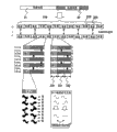
Figure 18 represents the summary of present embodiment.Address information is separated to be expressed as angle information part and orbit information.This angle information 31 and orbit information 32 are configured in each track alternately.Address information itself only disposes as groove swinging signal (along the micro-displacement of slot part radial direction) at slot part.The asymmetry that the reflection light quantity that this swinging signal can utilize groove to depart from the reproduced light that spot center produces distributes detects, and just can detect by push-pull signal.Though the tracking error signal of this push-pull signal when making hot spot follow the tracking servo of groove is identical, this servo be to move by the lens that make shaven head to carry out, thereby the servo frequency band of following is number kHz.Like this, if the signal more than pre-configured hundreds of kHz is as swinging signal, even make hot spot follow groove by servo-drive system so, because do not follow this swinging signal, so will produce owing to groove departs from the push-pull signal that spot center produces, and obtain swinging signal.
As shown in Figure 2, because flange part is the zone that is clipped between the adjacent trenches, so under the identical situation of the swing of adjacent trenches, flange part also can carry out identical swing, and flange part also is configured identical information.But in the different part of the information of adjacent trenches part, because flange portion is not pure " swing ", and the width of slot part is modulated, so can't make swinging signal regeneration.In the present invention, the angle information 310 in the middle of the interconnected information is all identical on whole tracks.As for staggered orbit information part 320, its zone is cut apart before and after further, is divided into following three parts, i.e. mark 330, the first orbit information zone 331, the second orbit information zone 332.It is different with the orbit information in the second orbit information zone to be recorded in first orbit information zone.In the drawings, in groove track Tr2-G, dispose " Tr1 ", " Tr2 " information as first and second orbit informations." Tr1 ", " Tr2 " are recorded in the first or second orbit information zone, and be all different in each staggered orbit information zone (section), but alternately configuration.In adjacent grooves track Tr3-G, configuration " Tr2 ", " Tr3 " information are as first and second orbit informations.In this case, the configuration of " Tr2 " makes " Tr2 " information in itself and the aforementioned track adjacent.That is,,, and in this flange track, also can from swinging signal, bear " Tr2 " information again so swinging signal is also identical because " Tr2 " information is identical in two groove track adjacent with flange track Tr2-L.But, in this flange track Tr2-L, having write down in the zone of " Tr1 " or " Tr3 " information in adjacent trenches portion, the information difference of adjacent orbit generally can't obtain the swinging signal of flange part in this zone.Therefore, only can correctly make " Tr2 " information regeneration at flange part.Because angle information all is identical in all tracks, so in the flange track, can certainly obtain the signal identical with the groove wobble signal of adjacent orbit.
The situation that is configured in the swinging signal in the mark part has been put down in writing in the bottom of Figure 18.At flange part, when the swinging signal of adjacent trenches is identical, though can obtain the sinuous signal identical as previously discussed with groove, under the different situation of the swinging signal of adjacent trenches, cancel out each other at the signal that flange part is adjacent, can only obtain the signal of little amplitude.Therefore, by pre-configured a pair of swing mark shown in Figure 18 lower left, at flange part, the consistent track of swing of the track of the swing unanimity of previous section and aft section alternately occurs.Like this, by the amplitude of more a pair of mark, can judge the phase place unanimity of which side in a pair of mark at flange part.Utilize this contrast, can judge which address is effective in first orbit information and second orbit information in platform part.That is, can utilize the selection signal of a pair of mark as the expression effective coverage.At groove, can be identical still different according to the front and back mark, judge which orbit information is effective in first and second.In following embodiment, the present invention is described in more detail with concrete numerical value.
(embodiment 2)
Fig. 2 represents the part enlarged drawing of the CD of one embodiment of the invention.Spiral groove 11 and flange 12 constitute information track on the disc wafer by being arranged on.User profile is recorded on platform 12 and the groove 11 as the different record mark 13 of reflectivity.Orbital spacing (mean distance between the center of adjacent trenches track and flange track) is 0.25 μ m.Groove forms the slot part that is arranged on the substrate, and the degree of depth of above-mentioned slot part approximately is 40nm.Because present embodiment is that hypothesis approximately is 405nm at wavelength, the aperture is than the regeneration that approximately is 0.85 bare headed enterprising line item, so the groove depth of this 40nm probably equals 1/6 optical range of wavelength.The amplitude of slot part is approximately 20nmpp, forms micro displacement (swing) along radial direction.
Shown in Fig. 1 (a), in swing, write down the information of the sine wave of corresponding one-period in the information " 1 ", write down the information that corresponding phase is carried out the sine wave of 180 degree counter-rotatings in the information " 0 ".Here, if the information spinner that is recorded in the swing has write down a kind of " address information ", its arbitrary region that is used on disc induces hot spot to carry out access, and the designated recorder zone, and this information generates when disc dispatches from the factory in advance.Because need carry out the identification of track, so in the address information of each track, write different information.Therefore, shown in Fig. 1 (b), the weave mode of each track is all different, can utilize this point identification track in regeneration.In Fig. 1 (b), in order to describe, shortened hunting period as shown in the figure, emphasize the wobble amplitude (, can't illustrate) of radial direction because actual wobble amplitude approximately is 8% of a track width.
Because swing is the physical displacement of groove, so normally in the disc substrates moulding, utilize mould to duplicate, thereby produce in enormous quantities.Under the situation of present embodiment, also be to utilize in advance to carry out making the mould (nickel pressing mold) that (mask fabrication) goes out after exposure imaging duplicates with Ultra-Violet Laser, by emission moulding (injection) device, make polycarbonate (PC) molding substrate of 1.1mm thickness duplicate the back use.In the present embodiment, overstock one deck phase change recording film on this PC substrate, with pressurize the in the above protective clear layer of 0.1mm of ultraviolet effect resin, forming integral thickness is the disc of 1.2mm then.
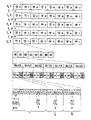
Fig. 5 represents how swinging address information is configured on each track.Fig. 5 only represents groove track T
GInformation.Each track is made of five words.Each word is made up of 13 section S0~S12, and each section is made up of 10 unit U0~U9.
Each unit is made up of the swing in 36 cycles, 18 of the first half swing expression angle informations, half the orbit informations of 1 bit of 18 swing expressions of back.The angle information of first half comprises partly whether expression is part " y " and the identification signal " x " of synchronizing symbol (SY), and all x, y are combined to form four kinds of patterns.The orbit information " z " of latter half of 1 bit of 18 swing expressions.
The information (angle information) of the first half that is comprised in each unit is SY1, SY2, w0, w1, w2 and s0-s4.SY1, SY2 represent that it is the sync mark of section head.In order to improve reliability (redundance), in each section, be provided with two.Represent word code with w0, w1, three bits of w2.Because five words are arranged on a track, so represent the word code of 0-4 with these three bits.S0-s4 is to be which section in each word with the section coded representation.Therefore, though only according to the information of any one section angle information of just can regenerating, thereby be identified in the position on the track inner periphery direction, but because in a track 5 * 13=65 section arranged, has sufficient redundance, the information of a plurality of sections so can regenerate, and it is comprehensively judged guarantee reliability.
The latter half of information in each unit is interconnected every a units alternately ground, and odd location keeps the information of four bits (a0-a3) of first address information, and even location keeps the information of four bits (b0-b3) of second address information.The record expression effective marking signal of which address information " ma " and " mb " in the u0 of head and u1.Should " ma " about utilizing, the regenerated signal of " mb " judges which address effective method narrates below.
Like this, because in each section, first and second address informations of 4 bits respectively keep 4 bits, so at a word, promptly respectively dispose the address information of 52 bits in 13 sections.
Fig. 6 represents the detailed content of these 52 bits.That is orbital number and the preparation position of 8 bits and the parity check code of 20 bits of 24 bits, have been write down.This parity check code is by the Galois body GF (2 that is a code element with 4 bits
4) after Reed Solomon code (Reed-Solomon sign indicating number) constitute.Like this, because 20 bits are 5 code elements, thus can revise the mistake of 2 code elements in 52 bits (13 code elements), and detect the mistake of 5 code elements.A among the figure, b are corresponding with first and second address informations.
Below by Fig. 7 mark (selection signal) is described.As mentioned above, though dispose " mark " that signal is selected in conduct in trench portions, this signal is that " 1 " or " 0 " is corresponding with marking signal in trench portions, and configuration is sinusoidal wave and phase place is carried out 180 sine waves of spending after reversing.On the flange track between the groove; swing according to the adjacent trenches track is identical or opposite; the amplitude difference of swinging signal is very big (though the desirable amplitude of time should be zero on the contrary; but in fact because various sum of errors aberrations can produce delicate imbalance, so can see some signals usually).Illustrated in fig. 18 identical with the foregoing description 1 utilized the very big this point of amplitude difference of swinging signal, can differentiate the marking signal of flange part.
Fig. 8 represents the collocation method of marking signal in each section.In the figure, T
G(4n) 4n groove track of expression.In 4n groove track, distribute to a pair of mark ma, mb with 0,1.In all sections of same rail, the information of mark is identical.In 4n+1 groove track, distribute to a pair of mark ma, mb, in 4n+2 groove track, distribute to a pair of mark ma, mb, in 4n+3 groove track, distribute to a pair of mark ma, mb 1,1 with 1,0 with 0,0.Like this, the flange portion of the marking signal of oval represented part between adjacent trenches is identical among the figure, and in other parts, the polarity of swinging signal is opposite.Therefore, as the explanation of Fig. 7, the oval marking signal of flange part partly that surrounds is greater than other parts among Fig. 8.For example, at T
G(4n) and T
GFlange track T (4n+1)
L(4n), the amplitude of mark ma can judge thus that greater than mb the first address information zone " a " is effective.Equally, at T
G(4n+1) and T
GFlange track T (4n+2)
L(4n+1), the amplitude of mark mb can judge thus that greater than ma the second address information zone " b " is effective.In trench portions, judge when ma is different with mb that " a " is effective, when equating, ma and mb judge that " b " is effective.For example, at groove T
G(4n), because ma is different with mb, so can judge that the first address information zone " a " is effective.
In the present embodiment, because a pair of mark is respectively arranged in each section, so 65 pairs of marks are arranged in each track.In addition because this 65 couple be configured to must be identical information, so detect a plurality of marks and make decision, can carry out the judgement of effective coverage reliably according to majority.In adjacent orbit, if utilize the effective coverage the position must before and after opposite this point, even in the zone of crossing over a plurality of tracks, also can improve the reliability of judgement.
Fig. 9 represents to be configured in the address information in first and second address areas.At groove track T
G(4n), configuration orbital number 4n in first address area " a ", configuration orbital number 4n-1 in second address area " b ".Like this, as mentioned above, because at groove track T
G(n) in, the first address information zone " a " is effective, so effectively address information (orbital number) is 4n.In addition, at groove track T
G(4n+1), configuration orbital number 4n in first address area " a ", configuration orbital number 4n+2 in second address area " b ".Like this, at groove track T
G(4n) and T
GFlange track T (4n+1)
L(4n), as mentioned above, second address information zone effectively.In first address area because the address of the groove track of adjacent both sides all is 4n, so flange part also can with groove refresh address from swinging signal equally, obtain 4n as address information.
In present embodiment (Fig. 5), the swing number of each track is 5 word * 13 sections * 10 unit * 36 swings=23400, and all fixes in all tracks on CD.That is, swing itself is to write down with the fixing CAV form of angular velocity.Be 6.4 μ m hunting period on the position that the interior all radiuses of CD are 22mm, and the most peripheral radius is to be 15.5 μ m on the position of 58mm.
In the present embodiment, the channel bit length that is recorded in the user data in flange track and the groove track is 0.06 μ m.Because the record that utilizes RLL (1,7) sign indicating number to carry out, so the shortest mark lengths is 0.12 μ m, user's bit length approximately is 0.9 μ m.The user capacity of CD integral body approximately is 50GB (single face).The linear velocity of control CD is fixed it during record.Promptly carry out the CLV record.In the present embodiment, the adjustment linear velocity is 12m/s, and the frequency that makes channel bit is 200MHz.Signal is regenerated with the PRML form during regeneration.Because the rotation of CD is the CLV form, thus CD interior week with about 5200rpm fast rotational, rotate at a slow speed with about 1900Hz in periphery.The frequency of swing is 2MHz at interior Zhou Dayue, approximately is 700KHz in periphery.Because the frequency of this frequency ratio channel bit is little more than one, so can not interfere swinging signal and user record signal.In addition, since also bigger two than the frequency band kHz of servo-drive system, so do not worry and can produce bad influence to servo-drive system.
(embodiment 3)
An example of the optical recording and reproduction apparatus of the CD that uses embodiment 2 is described below by Figure 10.Figure 11 represents to use the block scheme of the optical recording and reproduction apparatus of optical recording form of the present invention.From being calibrated to light beam 622 by collimation lens 624 into almost parallel as the light of the LASER Light Source 625 (wavelength approximately is 405nm in the present embodiment) of bare headed 620 parts emission.Light beam 622 is radiated on the CD 610 by object lens 623, forms hot spot 621.Afterwards, be imported into servo detecting device 626 and the signal detector 627 used by beam splitter 628 and holographic element 629 etc.The signal that each detecting device sends is handled servosignals such as forming tracking error signal and focus error signal through plus and minus calculation, is transfused in the servo circuit.Servo circuit is according to the tracking error signal and the focus error signal that obtain, the position of control objective lens actuator 631 and bare headed 620 integral body, and in the position of purpose record regenerating zone location hot spot 621.The plus signal of detecting device 627 is input in the signal regeneration zone 641.Input signal is undertaken by signal processing circuit 645 carrying out digitized processing after the change processing such as filtration treatment, frequency.The swing information of groove (slot part) is detected as the differential wave of cutting apart detecting device 627, and is imported into the wobble detection circuit 642 in the signal regeneration zone 641.Wobble detection circuit 642 generates and the synchronous clock of swinging signal, and has the effect of differentiating trochoidal wave form.Convert bit information by wobble detection circuit 642 detected swinging signals to by address bit testing circuit 643, afterwards, detect as address information by decoding circuit 646.According to detected address information, generate the signal that picks up counting that record regenerating is handled, the demodulator circuit 644 of control user data.Simultaneously, address information also is sent in the control circuit (microprocessor), is used for operations such as access.
The inner structure example of Wobble signal detection circuit is shown in Figure 11 (a).The differential wave (push-pull signal) of cutting apart detecting device 627 at first is input in the bandpass filter 421, and only extracts necessary frequency band.Signal after the filtration is input to and carries out digitizing in the A/D converter 422.Digital signal is input in the PLL circuit 425.PLL circuit 425 is made up of voltage-controlled oscillator (VCO) 426, carrier generation circuit (frequency division multiple circuit) 424 and frequency plot comparer 423.In the example of present embodiment, VCO 426 vibrates with 36 times of wobble channel clock frequencies to hunting frequency, and carries out 36 frequency divisions generation carrier wave by frequency dividing circuit 424.Carrier wave and digitized signal are carried out phase place and frequency contrast.The oscillation frequency of control VCO426 when controlling the CD rotation number according to comparing result, the result generates and the synchronous carrier wave of swinging signal.
In reference wave generative circuit 429, produce the sine wave signal identical as the reference waveform with the hunting frequency cycle.Swinging signal after this reference waveform and the digitizing is accumulated computing, and 427 couples of these results carry out the accumulation of 36 wobble channel bits with integrator.Accumulation results and wobble data 0,1 corresponding, form on the occasion of or negative value.Can judge 0,1 of swinging signal according to discriminator circuit 428 like this.
At flange part, under the opposite situation of the phase place of the trochoidal wave form of adjacent trenches, as the explanation of Fig. 7, the amplitude of swing reproduction waveform is roughly zero, and in this case, accumulation output also being roughly zero.Like this, can utilize the accumulation output valve, judge the size of flange part marking signal amplitude.As mentioned above, for marking signal, because from the size of the more a pair of mark amplitude of viewpoint expectation of detecting reliability, Discr. inside has storer (register) when judging so be desirably in, and differentiates by the amplitude of the flag signal group that relatively enters by the time sequence.
As described later, in the present embodiment because by over the ground amplitude being compared, can further improve reliability so compare by the amplitude of accumulating a plurality of marks.This structure will be explained hereinafter.
In addition, in the circuit structure of reality, make reference waveform generative circuit and multiplier integrated, and the long-pending and computing that multiplier is made fixed value, i.e. the structure of digital FIR filter-type can make circuit scale diminish and efficient.
In the kind of as above detected trochoidal wave form data address bit testing circuit 643 handled swing row in judging Figure 10, address bit is carried out synchronous processing, and detect address bit.Figure 11 (b) represents the structure of this address bit testing circuit.2 values of wobble detection circuit output 0,1 is imported in 36 the shift register, and is compared with the nethermost pattern of Fig. 5 one by one in each hunting period by pattern comparator 423.Because the pattern that forms " 10001 " only appears at the beginning part of each unit, detect units synchronization so when the beginning part is " 10001 ", be judged as, at this moment, pattern comparator 432 sends analogue synchronization signal to synchronizing circuit 434.When 36 swing detection go out this synchronizing signal, synchronizing circuit is considered as " synchronously ", and generates synchronizing signal.Because noise and defective in the time of swing detection; the not necessarily correct synchronizing signal of analogue synchronization signal from pattern comparator transmission itself; so synchronizing circuit 434 proof cycles are even exist defective also can generate the stable protected location synchronizing signal that produces like this.Output with units synchronization timer detecting pattern comparer 432 obtains x, the y of Fig. 5, the value of z.In each units synchronization, this value is input in the address detection circuit 433.Address detection circuit 433 is judged SY1 and the SY2 that each section begins from the pattern of x, y, z, detect word code and section code as the angle synchronizing information.Block section synchronization judging circuit 435 is checked the continuity of these word codes and section code, judge the block section synchronously, after the finishing synchronously of block section, just can obtain angular position information according to interior signal generating circuit 436 of week.Utilize this angular position information, make the remaining information of each section, be i.e. orbit information regeneration.
The output of integrator 427 sends in the A/B selection circuit 501 of Figure 12 among Figure 11.A/B selects circuit 501 to carry out the A/B switching according to the signal that obtains from the timing generative circuit based on synchronizing signal (angle information).In addition, 2 values of Figure 11 output is sent in the A/B selection circuit 509 of Figure 12.A/B selects circuit 509 to carry out the A/B switching according to the signal that obtains from the timing generative circuit based on synchronizing signal (angle information).Two A/B select, and basis is that even number unit or odd number unit switch (odd location is A, and even location is B, with reference to figure 5).By selecting circuit 501 A series to be sent in the amplitude storer of first series, B series is sent in the amplitude storer 505 of second series.In addition,, A series is sent in the demoder 504 of first series, B series is sent in the demoder 506 of second series by selecting circuit 509.The amplitude of each serial amplitude storer accumulation mark.In addition, according to the output of timing generative circuit, each serial demoder sends to 2 values output in the decoding circuit, carries out error correction at any time and detects decoding processing.Comparator circuit 503 is the accumulation mark amplitude of first and second series relatively, selects the output of first and second demoders according to the result, and exports as orbit information.The circuit of Figure 12 is equivalent to the decoding circuit 646 of Figure 10.
According to the circuit of present embodiment, because do not carry out the judgement of mark according to the amplitude of each mark, but the amplitude of accumulating a plurality of marks judges, so needn't worry to produce false judgment.As an other example, also can use and not accumulate amplitude and accumulate judged result (2 Value Data), the determination methods of making decision then according to majority, no matter which kind of method can be estimated judgement to mark highly reliably.In the latter's the example of making decision according to majority, reach 10% extreme low reliability even suppose the disconnected rate of the right erroneous judgement of label because have in a week 65 (to) mark, so the false detection rate that can guarantee address bit is less than 10
-15, and have sufficient high reliability in the practical application.Because in fact the actual measured value of the disconnected rate of Bai Dong erroneous judgement mostly is 2-3% most, so make decision the disconnected rate of erroneous judgement afterwards less than 10 according to majority
-32, and can guarantee extreme high reliability.
Each serial demoder is preferably in when the timing generative circuit is imported the data of a section in order at every turn and decodes among Figure 12.In the present embodiment, though address date is the Reed Solomon code (Reed-Solomon sign indicating number) that 4 bits with a section are 1 code element, but the address date (=orbital number) because of 5 words that belong to same rail is identical, so the parity check code of enclosing is also identical.Like this, even it is all not complete to belong to the data of 13 sections of each word, because if with the sector data combination of word in advance, just can constitute identical code, so can carry out the decoding of address information.For example, when access, under the situation that begins to read from the data of the section S3 of word 2, can determine synchronously according to the regeneration of S4, and begin the address date of section is input to the scrambler from S5.Under the situation of present embodiment mode, at first the S5 of word 2 is input in the demoder to S12, afterwards at the S0 that makes word 3 in S4 regeneration, because the data of all words are all complete, so can obtain decoded address information.In this case, in the present embodiment, parity check code does not use in correction and only uses in detection.Like this, though to ignore the probability of address detected mistake only be very little by 10
-6, but at the needs best decoded result of two continuous sections relatively under the situation of high reliability more.The probability of ignoring in this case is 10
-12
On the other hand, under the situation of existing swinging address form, because address code word is made of word cell, when word begins to read midway, wait until the beginning of next word, could begin the address is input in the demoder, so produce the stand-by period when regenerating, be not suitable for zero access in the address.But, in the mode of present embodiment, can produce the stand-by period hardly, as mentioned above, because can just can carry out the regeneration of address date, so can carry out zero access by the regeneration of an about word.
Another effect as the regeneration of present embodiment, because also can and regenerate midway at record, refresh address code in each section, and the current position of affirmation hot spot, even thereby owing to the impact that is subjected to the outside produces orbit displacement, also can detect at once, so be applicable in a lot of environment of external disturbance such as mobile phone and use.Especially under the situation that writes (one-time write) type record troactively, can carry out " repeating to write " when producing orbit displacement thereby the situation of destroying disc tracks because exist, so can detect orbit displacement at high speed, present embodiment has bigger value in this respect.
(embodiment 4)
The swinging address form of representing another one embodiment of the present invention with Figure 13.
In the present invention, also spiral groove 11 and flange 12 constitute information track on the discoid substrate by being arranged on, and user profile is recorded on flange part 12 and groove 11 two parts as the different record mark 13 of reflectivity.The interval of track (mean distance between adjacent trenches track and the flange orbit centre) is 0.34 μ m.Groove forms the slot part that is arranged on the substrate, and the degree of depth of above-mentioned slot part approximately is 35nm.Because the present embodiment hypothesis is approximately 405nm at wavelength, the aperture is than the bare headed enterprising line item regeneration that is approximately 0.65, so the groove depth of this 35nm roughly equates with the optical range of 1/7 wavelength.The slot part amplitude is about 25nmpp, forms micro displacement (swing) along radial direction.
Substrate utilization with swinging chute is carried out making the mould (nickel pressing mold) that (mask fabrication) goes out after exposure imaging duplicates with ultraviolet laser in advance, by emission moulding (injection) device, make polycarbonate (PC) molding substrate of 0.6mm thickness duplicate and create.In the present embodiment, press on this PC substrate after one deck write-once type recording film, bonding two groups of cards combine the one side of recording film, and forming integral body is the both-sided optical disc of 1.2mm.
Figure 13 represents how to dispose the information of swinging address on each track.Figure 13 only represents groove track T
GInformation.Each track is made of 7 words.Each word is made up of S0~S78 section, and each section is made up of U0~U67 unit.
Each unit is made up of the swing in 40 cycles, 20 swing expression angle informations of first half, the orbit information of latter half of 20 swing two bits of expression (a group).Angle information is made up of the part " y " and the angle information bit of expression synchronizing symbol (SY), has 4 kinds of patterns.In the present embodiment, after swing is modulated in MSK (Minimum Shift Keying) mode, the expression Bit data.In the MSK mode, represent wobble data " 0 " with the sine wave of one-period, represent wobble data " 1 " with the sine wave in 1.5 cycles.That is, the part of " 1 " is 1.5 times a frequency.
The first half information (angle information) that is comprised in each unit is SY, w0, w1, w2, s0-s3.SY is its sync mark that begins for section of expression.Three bits of w0, w1, w2 are represented word code.Because five words are arranged on a track, so represent the word code of 0-7 with these three bits.S0-s2 represents it is which section in each word with section code 0-7.Like this, though only by making the angle information regeneration of any one section, just can be identified in the position on the track inner periphery direction, but because in a track, have 8 * 8=64 section, has sufficient redundance, so can make the information regeneration of a plurality of sections, and it comprehensively be judged guarantee reliability.
Each unit latter half of all is divided into the zone " a " of representing first address information and the zone " b " of expression second address information.In the beginning unit of section U0, write down the expression effective signal of which address information " ma " and " mb ".Judge that with the regenerated signal of this " ma ", " mb " which address is effective.Residue comprises 6 group address data in the unit.That is, because in each section, first and second address informations of 6 bits maintain 4 bits separately, so at a word, promptly respectively dispose 48 bits in 8 sections.
Figure 14 represents the detailed content to these 48 bits.That is, the orbital number of three bytes of record (24 bits) and the parity check code of three bytes (24 bits).This parity check code is by the Galois body GF (2 that is a code element with 8 bits
8) after sign indicating number Reed Solomon code (Reed-Solomon sign indicating number) constitute.Like this, revise the mistake of 1 byte, just can detect the mistake of 3 bytes.A among the figure, b are corresponding with first and second address informations.
In the present embodiment, marking signal is identical with embodiment 2 with the collocation method of address information (orbital number).That is, as Fig. 8, configuration shown in Figure 9.
Because each section all respectively has a pair of mark in the present embodiment, so 64 pairs of marks are arranged in a track.In addition because these 64 pairs of marks be configured to must be identical information, so by detecting a plurality of marks, and make decision, just can judge highly reliably the effective coverage according to majority.If utilize effective coverage in the adjacent orbit the position must before and after opposite this point, even so in the zone of crossing over a plurality of tracks, also can improve the reliability of judgement.
In present embodiment (Figure 13), the swing number of each track is 8 word * 8 sections * 7 unit * 40 swings=17290, all fixes in these all tracks on CD.That is, swing itself is to write down with the fixing CAV form of angular velocity.Approximately be 9 μ m hunting period on the position that the interior all radiuses of CD are 24mm, is approximately to be 22 μ m on the position of 58mm at the most peripheral radius.
In the present embodiment, the length that is recorded in the channel bit of the user data in flange track and the groove track is 0.09 μ m.Because be the record that utilizes RLL (1,7) sign indicating number to carry out, so the shortest mark lengths is 0.18 μ m, the length of user's bit approximately is 1.35 μ m.The user capacity of CD integral body approximately is 22GB (single face).The linear velocity of control CD is fixed it when record.Promptly carry out the CLV record.In the present embodiment, the adjustment linear velocity is 1.35m/s, and the frequency number that makes channel bit is 150MHz.Signal is regenerated in the PRML mode during regeneration.Because the rotation of CD is the CLV form, thus CD interior week with about 5800rpm fast rotational, slowly rotate with about 2400Hz in periphery.Hunting frequency is 1.7MHz at interior Zhou Dayue, approximately is 700KHz in periphery.Because the frequency of this frequency ratio channel bit is little more than one, so can not interfere swinging signal and user record signal.In addition, since also bigger two than the frequency band kHz of servo-drive system, so do not worry and can produce bad influence to servo-drive system.
(embodiment 5)
The swinging address form of below representing another one embodiment of the present invention.
As shown in Figure 2, identical with embodiment 1, spiral groove 11 and flange 12 constitute information track of the present invention on the disc wafer by being arranged on.User profile is recorded on flange part 12 and the groove 11 as the different record mark 13 of reflectivity.Orbital spacing (mean distance between the center of adjacent trenches track and flange track) is 0.24 μ m.Groove forms the slot part that is arranged on the substrate, and the degree of depth of above-mentioned slot part approximately is 38nm.Present embodiment is to be approximately 405nm at wavelength, and the aperture is than the regeneration that is approximately 0.85 bare headed enterprising line item.The slot part amplitude is about 15nmpp, forms micro displacement (swing) along radial direction.
Shown in Fig. 1 (a), in swing, write down the sinusoidal wave information of corresponding one-period in the information " 1 ", write down the sinusoidal wave information that corresponding phase is carried out 180 degree counter-rotatings in the information " 0 ".That is, carry out record by phase modulation (PM) (Phase Shift Keying, PSK) mode.Here, be recorded in the arbitrary region of information on CD in the swing and induce hot spot to carry out access, essential record be used to specify the address information of posting field, it generates when CD dispatches from the factory in advance.
Because be necessary to carry out the identification of track, so in each track, write different information.Therefore, shown in Fig. 1 (b), can utilize the difference of weave mode in each track, identification track when regeneration.In Fig. 1 (b), in order to describe, shortened hunting period as shown in the figure, emphasize the wobble amplitude (, can't illustrate) on the radial direction because actual wobble amplitude approximately is 6% of a track width.
Swing is to utilize in advance to carry out making the mould (nickel pressing mold) that (mask fabrication) goes out after exposure imaging duplicates with ultraviolet laser, by emission moulding (injection) device, makes polycarbonate (PC) molding substrate of 0.6mm thickness duplicate the back use.In the present embodiment, on this PC substrate, press one deck phase change to write the type recording film troactively, and, form the CD of 0.7mm thickness in the above with the protective clear layer of ultraviolet effect resin pressurization 0.1mm.Matched with the back side of PC substrate one side in the CD back side of this 0.7mm thickness, forming integral thickness is the disc of 1.4mm.
Dispose the swinging address information (as shown in Figure 5) of each track similarly to Example 2.That is, each track is made of five words.Each word is made up of 13 section S0~S12, and each section is made up of 10 unit U0~U9.
Each unit is made up of the swing in 36 cycles, 18 swing expression angle informations of first half, the orbit information of a latter half of bit of 18 swing expressions.The angle information of first half comprises whether expression is part " y " and the identification signal " x " of synchronizing symbol (SY), and all x, y are combined to form 4 kinds of patterns.The orbit information " z " of a latter half of bit of 18 swing expressions.
The first half information (angle information) that is comprised in each unit is SY1, SY2, w0, w1, w2 and s0-s4.SY1, SY2 are its sync marks that begins for section of expression.In order to improve reliability (redundance), in each section, respectively dispose two.3 bits of w0, w1, w2 are represented word code.Because five words are arranged on first track, so represent the word code of 0-4 with these 3 bits.It is which section in each word to s0-s4 with the section coded representation.Like this, though only according to the information of any one section angle information of just can regenerating, thereby be identified in the position on the track inner periphery direction, but because in a track, have 5 * 13=65 section, has sufficient redundance, the information of a plurality of sections so can regenerate, and it is comprehensively judged guarantee reliability.
The latter half of information in each unit is interconnected every a units alternately ground, and odd location keeps the information of 4 bits (a0-a3) of " a " serial address information, and even location keeps the information of 4 bits (b0-b3) of " b " serial address information.The record expression effective signal of which address information " ma " and " mb " in u0 that begins and u1.
Like this, because in each section, " a " of 4 bits and the address information of " b " respectively maintain 4 bits, so at a word, promptly respectively dispose 52 bits in 13 sections, amount to the address information of 104 bits.
In these 104 bits, the first address information α and the second address information β are interconnected as shown in figure 15.This interconnected method is, in each section, the position of " a " be the position of the first address information α, " b " be the second address information β still in contrast, so alternately configuration on the contrary.In this first and second address information, respectively write down orbital number and the preparation bit of 8 bits and the parity check code of 20 bits of 24 bits.This parity check code is by the Galois body GF (2 that is a code element with 4 bits
4) after Reed Solomon code (Reed-Solomon sign indicating number) constitute.Like this, because 20 bits are 5 code elements, thus can revise the mistake of 2 code elements in 52 bits (13 code elements), and detect the mistake of 5 code elements.
Figure 16 represents the collocation method of marking signal in each section.In the figure, T
G(4n) 4n groove track of expression.With 0,1 a pair of mark ma, the mb that distributes to the section S0 of 4n groove track, with 0,0 a pair of mark ma, the mb that distributes to section S1.In same rail, distribute to the even number section (S0, S2 ...) and the odd number section (S1, S3 ... though) label information different, in all even number sections, the information of mark is identical, in addition, the label information in all odd number sections is also identical.In 4n+1 groove track, with 0,0 mark ma, the mb that distributes to the even number section, with 1,0 mark ma, the mb that distributes to the odd number section.In 4n+2 groove track, with 1,0 mark ma, the mb that distributes to the even number section, with 1,1 mark ma, the mb that distributes to the odd number section.Then, in 4n+3 groove track, with 1,1 mark ma, the mb that distributes to the even number section, with 0,1 mark ma, the mb that distributes to the odd number section.Like this, the flange portion of the marking signal of oval represented part between adjacent trenches is identical among the figure, and in other parts, the polarity of swinging signal is opposite.Therefore, explanation as in the previous examples, the oval marking signal of flange part partly that surrounds is greater than other parts among Figure 16.For example, at T
G(4n) and T
GFlange track T (4n+1)
LEven number section (4n) (S0, S2 ...) in, the amplitude of mark ma can judge thus that greater than mb the first address information zone " a " is effective.In addition, at groove track T
G(4n) and T
GFlange track T (4n+1)
LOdd number section (4n) (S1, S3 ...) in, the amplitude of mark ma can judge thus that greater than mb the first address information zone " a " is effective.At groove, when ma is different with mb, judge that " a " is effective, when ma is equal with mb, judge that " b " is effective.For example, because at groove T
GMa is different with mb in the even number section (4n), so can judge that the first address information zone " a " is effective.
In the present embodiment, because a pair of mark is respectively arranged in each section, so 65 pairs of marks are arranged in each track.In addition, because the configuration of these 65 pairs of marks must interlock the effective coverage,, can carry out the judgement of effective coverage reliably according to its continuity so detect a plurality of marks.Further because the sector number of each track is an odd number, even thereby in part across track, in the adjacent orbit position of effective coverage also must before and after opposite.Utilize this point,, and utilize in each section effective coverage this point on the contrary, improve the reliability of judgement easily even in crossing over the zone of a plurality of tracks, also can not judge the border of track.That is, in this embodiment,, detect so can realize the effective coverage of high reliability more easily because needn't know effective coverage middle orbit boundary information.
Figure 17 represents to be configured in the address information in first and second address areas.At groove track T
GIn the even number section (4n), configuration orbital number 4n in first address area " a ", configuration orbital number 4n-1 in second address area " b ".In addition, at groove track T
GIn the odd number zone (4n), configuration orbital number 4n-1 in first address area " a ", configuration orbital number 4n in second address area " b ".Like this, as mentioned above, because the first address information zone " a " is at groove track T
G(n) effective in the even number zone, so effective address information (orbital number) is 4n, in addition, and as mentioned above, because the second address information zone is at groove track T
G(n) effective in the odd number zone, so effective address information (orbital number) is 4n equally.On the flange track, in Figure 16, use effective coverage one side of ellipse representation, because the address information that is configured on the side grooves track shown in Figure 17 is identical, thus the same with embodiment 2, flange portion can with trench portions equally from the swinging signal address of regenerating.
In the present embodiment, the swing number of each track is 5 word * 13 sections * 10 unit * 36 swings=23400, all fixes in its all tracks on disc.That is, swing itself is to write down with the fixing CAV form of angular velocity.Be 6.4 μ m hunting period on the position that the interior all radiuses of CD are 22mm, and the most peripheral radius is to be 15.5 μ m on the position of 58mm.
In the present embodiment, the channel bit length that is recorded in the user data in flange track and the groove track is 0.06 μ m.Because record is to carry out with RLL (1,9) sign indicating number, so the shortest mark lengths is 0.12 μ m, user's bit length approximately is 0.9 μ m.The user capacity of CD integral body approximately is 100GB (two-sided).
The linear velocity of control CD is fixed it when record.That is, carry out the CLV record.In the present embodiment, the adjustment linear velocity is 12m/s, and the frequency that makes channel bit is 200MHz.Signal is regenerated in the PRML mode when regeneration.Because the rotation of CD is the CLV form, thus CD interior week with about 5200rpm fast rotational, slowly rotate with about 1900Hz in periphery.Hunting frequency is 2MHz at interior Zhou Dayue, approximately is 700KHz in periphery.Because the frequency of this frequency ratio channel bit is little more than two, so can not interfere swinging signal and user record signal.In addition, since also bigger two than the frequency band kHz of servo-drive system, so do not worry and can produce bad influence to servo-drive system.
The present invention is not limited to the foregoing description.For example, also can use magneto-optic recording medium and pigment type to write medium troactively as recording layer.The multi-layer recording medium that also can be used in addition, record independent information on the recording layer more than two-layer.Also different in this case with existing flange way grooved address mode, need not use " title ", thereby can suppress interlayer interference.Can certainly be applicable to many-valued recording mode.In addition, the modulation code as swing utilizes QPSK can certainly obtain identical effect with Modulation and Amplitude Modulation, frequency modulation (PFM).Under any circumstance, under situation identical and different situation, can utilize trochoidal wave form to change this point, detect and judge the effective coverage selected marker in flange part regeneration with the trochoidal wave form of side grooves portion.
As previously discussed, swinging address mode of the present invention realizes that easily address signal is synchronous, that is, and and refresh address signal at high speed.In addition, can utilize effective modulation system of address signal and redundance to detect address information reliably.This effect especially shows in the middle of the optical recording regeneration that utilizes the often low blue-light source of signal light quantity and regeneration quality.In addition,, and do not need to utilize the embossing indenture, just can write the media information of necessity in the recording type optical disc because in swing, kept other additional datas of address information, thereby can the cheap CD of also easily realizing high reliability (highly confidential).Importing by high detection rate swing of the present invention has realized first by the maintenance of swing to additional data.
In addition, the present patent application comprises following structure.
1. carrier with a plurality of tracks, it is characterized by: each track has a plurality of sections at least, in at least two sections of same rail, has the redundance that comprises identical information, the configuration of above-mentioned redundance makes as long as taking out arbitrary portion from the each several part of a plurality of sections of disposing identical information synthesizes, just can recover original information.
2. carrier with a plurality of tracks, it is characterized by: each track has a plurality of sections at least, in at least two sections of same rail, comprise identical information, in above-mentioned identical information at least additional phase with the information that is used for error detection/correction, itself and above-mentioned address information are configured in each section jointly.
CD of the present invention can use the swinging address mode that helps format efficiency with the flange way grooved record that can realize narrow gauge trackization is combined, thereby can realize carrying out the huge capacity compact discs and the renovation process of high density recording.
Claims (4)
1. information reproduction method, it is information reproduction method with carrier of first and second address informations, this carrier has a plurality of tracks, wherein, above-mentioned track along the circumferential direction has at least one section, in above-mentioned each section, has the address information zone, above-mentioned address information zone along the circumferential direction has first address information zone and the second address information zone, in above-mentioned each section, record the signal that is used to read address information, above-mentioned signal is which of above-mentioned first address information of expression zone and the above-mentioned second address information zone is the effective choice signal, comprising:
Above-mentioned first and second address informations are regenerated/decoded, estimate the reliability of each address information, and from above-mentioned first and second address informations, select the high address information of reliability to regenerate, wherein
The amplitude of the selection signal by relatively distinguishing corresponding first address information zone and the second address information zone, the high address information of selection reliability.
2. information reproduction method according to claim 1 is characterized in that, above-mentioned evaluation is to be undertaken by the amplitude of accumulating a plurality of these signals.
3. information reproduction method according to claim 1 is characterized in that, above-mentioned carrier is the recording medium that writes type troactively.
4. information reproduction method, it is used to have the carrier of a plurality of tracks, in this carrier, above-mentioned track along the circumferential direction has at least one section, in above-mentioned each section, has the address information zone, above-mentioned address information zone along the circumferential direction has first address information zone and the second address information zone, in above-mentioned each section, record the signal that is used to read address information, above-mentioned signal is which of above-mentioned first address information of expression zone and the above-mentioned second address information zone is the effective choice signal, comprising:
Utilization has the carrier of which effective choice signal of expression first and second address informations and above-mentioned first and second address informations, when the above-mentioned selection signal of regeneration is judged, undertaken by a plurality of selection signals of regenerating, wherein,
Above-mentioned first and second address informations are regenerated/decoded, the amplitude of the selection signal in corresponding first address information zone of accumulation difference in a rail and the second address information zone, the amplitude of correspondence first address information zone by relatively accumulation and the selection signal in the second address information zone, the high address information of selection reliability is carried out information regeneration; Perhaps make the staggered rule of effective address information area according to the configuration of selecting signal, detect the continuity of the selection signal of distinguishing corresponding first address information zone and the second address information zone in this track, select the high address information of reliability to carry out information regeneration.
Applications Claiming Priority (2)
| Application Number | Priority Date | Filing Date | Title |
|---|---|---|---|
| JP2003056518 | 2003-03-04 | ||
| JP2003056518A JP4228727B2 (en) | 2003-03-04 | 2003-03-04 | Information recording medium and information reproducing method |
Publications (2)
| Publication Number | Publication Date |
|---|---|
| CN1527294A CN1527294A (en) | 2004-09-08 |
| CN100583251C true CN100583251C (en) | 2010-01-20 |
Family
ID=32923526
Family Applications (1)
| Application Number | Title | Priority Date | Filing Date |
|---|---|---|---|
| CN03154087A Expired - Fee Related CN100583251C (en) | 2003-03-04 | 2003-07-29 | Information reproducing method |
Country Status (3)
| Country | Link |
|---|---|
| US (2) | US7417942B2 (en) |
| JP (1) | JP4228727B2 (en) |
| CN (1) | CN100583251C (en) |
Cited By (1)
| Publication number | Priority date | Publication date | Assignee | Title |
|---|---|---|---|---|
| CN104603879A (en) * | 2013-05-31 | 2015-05-06 | 松下知识产权经营株式会社 | Optical disc medium and optical disc device |
Families Citing this family (10)
| Publication number | Priority date | Publication date | Assignee | Title |
|---|---|---|---|---|
| KR101063081B1 (en) * | 2004-05-11 | 2011-09-07 | 파나소닉 주식회사 | Wobble information recording method, information recording medium, and recording and reproduction method and apparatus thereof |
| CN100458934C (en) * | 2004-07-12 | 2009-02-04 | 松下电器产业株式会社 | Information recording medium, integrated circuit, recording/reproducing device, computer program, and information recording/reproducing method |
| US8218412B2 (en) * | 2007-11-05 | 2012-07-10 | Mediatek Inc. | Method and system for determining disc format for recovery of data recording |
| US8874775B2 (en) * | 2008-10-15 | 2014-10-28 | Aster Risk Management Llc | Balancing a distributed system by replacing overloaded servers |
| TWI539446B (en) * | 2012-05-30 | 2016-06-21 | Sony Corp | Optical information recording medium and optical information recording medium reproduction device |
| EP2674731B1 (en) * | 2012-06-13 | 2015-09-02 | Dr. Johannes Heidenhain GmbH | Position measuring device |
| JP2014032711A (en) * | 2012-08-01 | 2014-02-20 | Hitachi Consumer Electronics Co Ltd | Optical information recording medium, recording and playback method, and recording and playback device |
| JP2014063553A (en) * | 2012-09-24 | 2014-04-10 | Sony Corp | Optical information recording medium and optical information recording medium reproduction device |
| DE102013222197A1 (en) * | 2013-10-31 | 2015-04-30 | Dr. Johannes Heidenhain Gmbh | Position measuring device |
| JP6937468B2 (en) * | 2018-03-06 | 2021-09-22 | パナソニックIpマネジメント株式会社 | Information recording device and data erasure method |
Family Cites Families (10)
| Publication number | Priority date | Publication date | Assignee | Title |
|---|---|---|---|---|
| US5452284A (en) * | 1992-09-14 | 1995-09-19 | Matsushita Electric Industrial Co., Ltd. | Optical recording/reproducing medium and apparatus using land and groove encoded information signals and identification signals including position information |
| JP3301524B2 (en) | 1995-08-04 | 2002-07-15 | ソニー株式会社 | optical disk |
| JP3063613B2 (en) * | 1996-03-25 | 2000-07-12 | 三菱電機株式会社 | Optical disk medium and optical disk device |
| JP2856390B2 (en) | 1996-07-26 | 1999-02-10 | 株式会社日立製作所 | Information recording medium and recording / reproducing method using the same |
| KR100324883B1 (en) * | 1996-09-26 | 2002-02-28 | 다카노 야스아키 | Recording medium and its reproducer |
| EP1098302A3 (en) * | 1999-11-03 | 2007-12-12 | SAMSUNG ELECTRONICS Co. Ltd. | Physical identification data addressing method using wobble signal, wobble address encoding circuit, method and circuit for detecting wobble address, and recording medium |
| JP3954280B2 (en) * | 2000-05-23 | 2007-08-08 | 株式会社東芝 | Optical disc, reproducing method and reproducing apparatus |
| AU2002219541A1 (en) * | 2000-12-26 | 2002-07-08 | Matsushita Electric Industrial Co., Ltd. | Recording medium, recording method, reproduction method, recording apparatus and reproduction apparatus |
| JP2003203347A (en) * | 2001-12-28 | 2003-07-18 | Toshiba Corp | Information storage medium, information recording device, information reproducing device, information recording method, and information reproducing method |
| US7376056B2 (en) * | 2002-01-21 | 2008-05-20 | Matsushita Electric Industrial Co., Ltd. | Method and apparatus for reading address information from an optical disc medium |
-
2003
- 2003-03-04 JP JP2003056518A patent/JP4228727B2/en not_active Expired - Fee Related
- 2003-07-29 CN CN03154087A patent/CN100583251C/en not_active Expired - Fee Related
- 2003-08-13 US US10/639,724 patent/US7417942B2/en not_active Expired - Fee Related
-
2007
- 2007-06-07 US US11/759,558 patent/US20070230319A1/en not_active Abandoned
Cited By (2)
| Publication number | Priority date | Publication date | Assignee | Title |
|---|---|---|---|---|
| CN104603879A (en) * | 2013-05-31 | 2015-05-06 | 松下知识产权经营株式会社 | Optical disc medium and optical disc device |
| CN104603879B (en) * | 2013-05-31 | 2019-03-08 | 松下知识产权经营株式会社 | CD media |
Also Published As
| Publication number | Publication date |
|---|---|
| JP2004265546A (en) | 2004-09-24 |
| CN1527294A (en) | 2004-09-08 |
| JP4228727B2 (en) | 2009-02-25 |
| US20070230319A1 (en) | 2007-10-04 |
| US20040174792A1 (en) | 2004-09-09 |
| US7417942B2 (en) | 2008-08-26 |
Similar Documents
| Publication | Publication Date | Title |
|---|---|---|
| CN1501365B (en) | Record carrier and method of providing a record carrier | |
| KR100318359B1 (en) | Optical disc | |
| TW382124B (en) | Record reading method and apparatus employing information recording media | |
| KR0132674B1 (en) | Optically readable record carrier and mamufacturing apparatus and recording and reading apparatus | |
| CN1554092B (en) | Recording method, and disc drive device | |
| US20070230319A1 (en) | Information recording medium and information reproduction method | |
| JP4090879B2 (en) | RECORDING MEDIUM, CONTROL DEVICE THEREOF, AND CONTROL METHOD THEREOF | |
| PL197778B1 (en) | Record carrier and apparatus for scanning the record carrier | |
| JP3899861B2 (en) | Optical disc, information reproducing method and recording method | |
| CN100388363C (en) | Information recording medium and information recording/ reproducing device and method | |
| US20080205211A1 (en) | Structure and method for storing data on optical disks | |
| EP1207531A2 (en) | Optical storage medium | |
| EP0674314B1 (en) | A data recording medium, an optical disk and an optical disk apparatus | |
| KR0136098B1 (en) | Method and apparatus for successively recording efm modulated signals | |
| KR20030005313A (en) | Recording/reproducing device | |
| JP2006269077A (en) | Optical information recording medium | |
| KR20020091259A (en) | Recording/reproducing device | |
| JP2008041247A (en) | Information recording medium and information reproducing method | |
| JP3897095B2 (en) | Optical information recording medium | |
| CN103456325A (en) | Optical information recording medium and reproducing apparatus | |
| TW386227B (en) | Optical disk and apparatus for forming optical disk prototype and optical disk apparatus | |
| JP5069261B2 (en) | Optical information recording medium | |
| JP3901150B2 (en) | Optical disc, information reproducing method and recording method | |
| JP4966336B2 (en) | Optical disc and information recording and reproducing method | |
| MXPA00009399A (en) | Record carrier and apparatus for scanning the record carrier |
Legal Events
| Date | Code | Title | Description |
|---|---|---|---|
| C06 | Publication | ||
| PB01 | Publication | ||
| C10 | Entry into substantive examination | ||
| SE01 | Entry into force of request for substantive examination | ||
| C14 | Grant of patent or utility model | ||
| GR01 | Patent grant | ||
| C17 | Cessation of patent right | ||
| CF01 | Termination of patent right due to non-payment of annual fee |
Granted publication date: 20100120 Termination date: 20130729 |