CN100582520C - Disc braker - Google Patents
Disc braker Download PDFInfo
- Publication number
- CN100582520C CN100582520C CN200610071470A CN200610071470A CN100582520C CN 100582520 C CN100582520 C CN 100582520C CN 200610071470 A CN200610071470 A CN 200610071470A CN 200610071470 A CN200610071470 A CN 200610071470A CN 100582520 C CN100582520 C CN 100582520C
- Authority
- CN
- China
- Prior art keywords
- dish
- brake pad
- piece
- radially
- guiding board
- Prior art date
- Legal status (The legal status is an assumption and is not a legal conclusion. Google has not performed a legal analysis and makes no representation as to the accuracy of the status listed.)
- Active
Links
Images


Classifications
-
- F—MECHANICAL ENGINEERING; LIGHTING; HEATING; WEAPONS; BLASTING
- F16—ENGINEERING ELEMENTS AND UNITS; GENERAL MEASURES FOR PRODUCING AND MAINTAINING EFFECTIVE FUNCTIONING OF MACHINES OR INSTALLATIONS; THERMAL INSULATION IN GENERAL
- F16D—COUPLINGS FOR TRANSMITTING ROTATION; CLUTCHES; BRAKES
- F16D65/00—Parts or details
- F16D65/02—Braking members; Mounting thereof
- F16D65/04—Bands, shoes or pads; Pivots or supporting members therefor
- F16D65/092—Bands, shoes or pads; Pivots or supporting members therefor for axially-engaging brakes, e.g. disc brakes
- F16D65/095—Pivots or supporting members therefor
- F16D65/097—Resilient means interposed between pads and supporting members or other brake parts
- F16D65/0973—Resilient means interposed between pads and supporting members or other brake parts not subjected to brake forces
- F16D65/0974—Resilient means interposed between pads and supporting members or other brake parts not subjected to brake forces acting on or in the vicinity of the pad rim in a direction substantially transverse to the brake disc axis
- F16D65/0977—Springs made from sheet metal
-
- F—MECHANICAL ENGINEERING; LIGHTING; HEATING; WEAPONS; BLASTING
- F16—ENGINEERING ELEMENTS AND UNITS; GENERAL MEASURES FOR PRODUCING AND MAINTAINING EFFECTIVE FUNCTIONING OF MACHINES OR INSTALLATIONS; THERMAL INSULATION IN GENERAL
- F16D—COUPLINGS FOR TRANSMITTING ROTATION; CLUTCHES; BRAKES
- F16D65/00—Parts or details
- F16D65/02—Braking members; Mounting thereof
- F16D65/04—Bands, shoes or pads; Pivots or supporting members therefor
- F16D65/092—Bands, shoes or pads; Pivots or supporting members therefor for axially-engaging brakes, e.g. disc brakes
- F16D65/095—Pivots or supporting members therefor
- F16D65/097—Resilient means interposed between pads and supporting members or other brake parts
- F16D65/0972—Resilient means interposed between pads and supporting members or other brake parts transmitting brake reaction force, e.g. elements interposed between torque support plate and pad
Landscapes
- Engineering & Computer Science (AREA)
- General Engineering & Computer Science (AREA)
- Mechanical Engineering (AREA)
- Braking Arrangements (AREA)
Abstract
The invention discloses a disc-typed brake, which is characterized by the following: guide board part, radial forcing part (16) and rotary forcing part (19) on the block spring (10), wherein the projecting part (16D) is bent toward inner radial direction from length direction on the forcing piece part (16C) of radial forcing part 16, which is mated on the position of gap part (18) of lower panel (14B); the broad plate slopes internal radial of disc (1) from lower panel (14B); rathe lower panel (14B) of guide board part (14) and rotary forcing part (19) can press friction block (7) along rotary direction of disc (1).
Description
Technical field
The present invention relates to be suitable for most giving for example employed disk type braker of car brakeing power of automobile etc.
Background technique
Usually, be located at disk type braker on the vehicle such as automobile by constituting as lower member etc., that is, assembly, it is installed on the non-rotating part of vehicle, has the sense of rotation of leaving dish and vertically across a pair of wrist of the periphery of dish; Brake calipers, it is located on each wrist of this assembly slidably, and a pair of brake pad (friction パ Star De) is pressed on the two sides of dish; And pair of block spring (パ Star De ス プ リ Application グ), it is installed on each wrist side of above-mentioned assembly respectively, and between each wrist the above-mentioned a pair of brake pad of yielding support (for example with reference to patent documentation 1).
The disk type braker of this prior art waits when carrying out brake operating the driver of vehicle, is used to from outside hydraulic pressure supply the piston of being located at the brake calipers inboard be slided to the dish side, and the brake pad of inboard is pressed on the dish.And the reaction force by brake calipers thus the time is pressed into each brake pad on the two sides of dish the dish braking force of rotating with respect to the assembly displacement of sliding between claw and the piston outside it.
At this moment, each wrist at assembly is provided with the piece guide that axially guides a pair of brake pad slidably that is used at dish.And it is loosening with respect to the piece guide of each wrist etc. that above-mentioned spring suppresses brake pad, thereby make the slip displacement of brake pad smooth and easy.
That is, this piece spring for example has by punch process that flexible sheet metal etc. forms.And, the piece spring that constitutes the sense of rotation inlet side that is positioned at dish in the pair of block spring (below be called screw in side) is provided with the afterburning reed of piece of elongated plate-like, U-shaped forms and extends to the axioversion that coils this reed by being flexed into roughly, and utilizes the afterburning reed of this piece to sense of rotation (circumferentially) reinforcing of brake pad at dish.
On the other hand, the piece spring that constitutes the sense of rotation outlet side that is positioned at dish (below be called screw out side) is provided with and bears the piece that acts on the retarding torque on the brake pad with the wrist that screws out side and bear board, and utilize piece bear board suppress brake pad with respect to assembly to the relative displacement of the sense of rotation (circumferentially) of dish.
Patent documentation 1: open flat 5-89978 communique in fact
But, loosening in order to suppress brake pad in above-mentioned prior art in the sense of rotation of dish, and the afterburning reed of piece is set on the piece spring that screws in side.But U-shaped forms the afterburning reed of this piece by being flexed into roughly as its terminal side, and the reed of its forward end elongated plate-like of extending to the axioversion of dish and being shaped.
For this reason, the piece spring of prior art produces following such problem.Promptly, because the afterburning reed of piece forms the reed to the elongated plate-like of the axioversion extension of dish, so brake pad is occurred great changes at the afterburning active force of the sense of rotation (circumferentially) of dish (paying Potential power) (elastic load of the afterburning reed of piece) when brake pad is brand-new and during wearing and tearing, and therefore existence is difficult to described active force is made as constant problem.
In addition, have at the terminal side of the afterburning reed of piece and to be flexed into the roughly joggling part of U-shaped, this joggling part stretches out to the axial outside of dish significantly from the piece guide of assembly.
Therefore, when being installed to the piece spring on the assembly, when being assembled into brake pad on the piece spring, the joggling part of the afterburning reed of piece constitutes obstacle, when at assembling operation, touch joggling part mistakenly and when it is applied external force, have the possibility that the active force that makes the afterburning reed integral body of piece changes.
And, because the afterburning reed of piece is the reed to the elongated plate-like of the axioversion extension of dish, so there are the following problems, promptly, for brake pad add force direction also with respect to the dish plane inclination, the attitude of brake pad becomes the state of inclination with respect to dish, thereby the problem of reason that the sliding properties of brake pad reduces etc. occurs becoming.
Summary of the invention
The present invention develops in view of above-mentioned prior art problems, the objective of the invention is to, a kind of disk type braker is provided, can make the attitude stabilization of brake pad with respect to dish, suppress the loosening generation that waits, and vibration, the break that can the prevent brake pad generation of ringing etc.
For solving above-mentioned problem, the present invention is applicable to disk type braker, this disc type brake its by constituting as lower member: assembly, its have on the sense of rotation of dish, leave and axially across a pair of wrist of the outer circumferential side of this dish, and on this each wrist, be provided with the piece guide; Brake calipers, it is located on each wrist of this assembly slidably; A pair of brake pad, it is slidably mounted on each wrist of described assembly by described guide, and is pressed into by this brake calipers on the two sides of dish; And the pair of block spring, it is installed on each wrist side of described assembly respectively, and between each wrist this each brake pad of yielding support.
And, the structure that the invention of scheme 1 is adopted is characterised in that a piece spring in the described pair of block spring is following structure, and it has: the guiding board, it is chimeric and be installed on the piece guide of described assembly, with this piece guide at the described brake pad of axial lead; Radially afterburning portion, it forms along extending axially of dish between this guiding board and brake pad, to the radial outside reinforcing of described brake pad to dish; And sense of rotation reinforcing portion, it forms from the tabular body of described guiding board to the wide cut of the radially inner side inclination warpage of dish, and is afterburning on the sense of rotation of dish to described brake pad.
In addition, invention according to scheme 2, it is following structure, described spring is provided with described guiding board and is embedded in claw on the piece guide of described assembly, this claw by with the wall Elastic Contact of the radially inner side of the dish of described guide to of the radial outside reinforcing of the relative piece guide of described guiding board to dish.
On the other hand, invention according to scheme 3, be following structure: at projection piece from the length direction of described radially afterburning portion to the inside direction warpage in footpath of dish is set midway, be provided with on the described guiding board when described radially afterburning portion towards the radially inner side displacement of dish and when leading board, allow the gap part that described projection piece contacts with the side surface side of piece guide.
In addition, invention according to scheme 4, be following structure: it is free end axially extended elongated plate-like body along dish between described guiding board and brake pad towards the radial outside warpage of dish for roughly U-shaped, its forward end that described radially afterburning portion forms its terminal side, and is formed with between described radially afterburning portion and guiding board and is used to make described sense of rotation reinforcing portion and radially afterburning portion is separate and the otch of resiliently deformable.
According to the invention of scheme 5, be following structure: a piece spring in the described pair of block spring is mounted in the screw-in lateral mass spring on the wrist of the screw-in side that is positioned at dish in each wrist of described assembly.
In addition, the structure that the invention of scheme 6 is adopted is characterised in that, is following structure: a piece spring in the described pair of block spring has: the guiding board, it is chimeric and be installed on the piece guide of described assembly, with this piece guide at the described brake pad of axial lead; And radially afterburning portion, it forms along extending axially of dish between this guiding board and brake pad, to of the radial outside reinforcing of described brake pad to dish,
Described spring is provided with described guiding board and is embedded in claw on the piece guide of described assembly, this claw by with the wall Elastic Contact of the radially inner side of the dish of described guide to of the radial outside reinforcing of the relative piece guide of described guiding board to dish
At projection piece from the length direction of described radially afterburning portion to the inside direction warpage in footpath of dish is set midway, be provided with on the described guiding board when described radially afterburning portion towards the radially inner side displacement of dish and when leading board, allow the gap part that described projection piece contacts with the side surface side of piece guide.
Invention according to scheme 7, be following structure: it is free end axially extended elongated plate-like body along dish between described guiding board and brake pad towards the radial outside warpage of dish for roughly U-shaped, its forward end that described radially afterburning portion forms its terminal side, and is formed with between described radially afterburning portion and guiding board and is used to make described sense of rotation reinforcing portion and radially afterburning portion is separate and the otch of resiliently deformable.
As mentioned above, according to scheme 1 described invention, owing on the piece spring in the pair of block spring guiding board is set, radially afterburning portion and sense of rotation reinforcing portion, this sense of rotation reinforcing portion is in order to form from the tabular body of described guiding board to the wide cut of the radially inner side inclination warpage of dish to the sense of rotation reinforcing of coiling brake pad, therefore, compared with prior art, even when brake pad is brand-new and wearing and tearing the time active force (load on spring) of sense of rotation reinforcing portion can both be made as constant, can be to sense of rotation (for example sense of rotation outlet side) the stable constantly reinforcing of brake pad to dish.In addition, because this sense of rotation reinforcing portion is crooked obliquely to the radially inner side of dish from the guiding board, so on assembly during the assembled block spring, sense of rotation reinforcing portion can not constitute obstacle, can improve the operability when assembling.
And, sense of rotation reinforcing portion can make for brake pad add force direction with the direction of plane almost parallel of dish on orientation, can prevent that brake pad from coiling inclination relatively.Therefore, by by such sense of rotation reinforcing portion to the sense of rotation reinforcing of brake pad to dish, can make the relatively attitude stabilization of dish of brake pad, and can keep the sliding properties etc. of brake pad well.In addition, can by be located at radially afterburning portion on the piece spring and sense of rotation reinforcing portion inhibition dish radially, the brake pad of sense of rotation (circumferentially) loosening, and can suppress the vibration of brake pad well, simultaneously, the generation that can prevent that break from ringing etc.
In addition, invention according to record in the scheme 2, because at the claw that is provided with on the piece spring on the piece guide that is entrenched in assembly with the board that leads, so by making the wall Elastic Contact of this claw and described guide, the piece guide of assembly is to the radial outside reinforcing to dish of the guiding board of piece spring relatively, can make sense of rotation reinforcing portion leave the piece guide, make the active force of sense of rotation reinforcing portion stable.
On the other hand, invention according to record in the scheme 3, because the radially afterburning portion at the piece spring that adopts is provided with projection piece, the structure of gap part is set at the guiding board, even so axially extended radially afterburning portion that coil on the edge between guiding board and brake pad, since for example the vibration during brake operating etc. and to add the opposite direction displacement of force direction (to the direction of brake pad) to the radial outside reinforcing of dish, at this moment, described projection piece also can contact with the side surface side of piece guide and bear the external force of following vibration etc., thereby can prevent the excessive stress of effect in afterburning portion radially etc.Therefore, as mentioned above, radially afterburning portion overlaps with the board that leads powerfully and is out of shape in the time of can utilizing described projection piece to prevent that vibration from producing, and the stress that can suppress for example radially afterburning portion and guiding board is concentrated, simultaneously, durability, life-span of piece spring integral body etc. can be improved, thereby reliability can be improved.
In addition, the invention of record in the scheme 4 and 7, because for the structure of otch is set between radially afterburning portion and guiding board, so can make sense of rotation reinforcing portion and radially afterburning portion resiliently deformable independently of each other, thereby for example can prevent that radially the distortion of afterburning portion gives sense of rotation reinforcing portion to influence.Therefore, the unnecessary stress of effect in radially afterburning portion and sense of rotation reinforcing portion can be prevented, thereby the concentrated generation that waits of stress can be suppressed.And, can make both separate for the active force of brake pad, make the attitude of piece and the attitude stabilization of piece spring itself.
Invention according to record in the scheme 6, because at the claw that is provided with on the piece spring on the piece guide that is embedded in assembly with the board that leads, therefore can be by making the wall Elastic Contact of this claw and described guide, the piece guide of assembly, can stably be installed in the guiding board on the piece guide to the radial outside reinforcing of coiling the guiding board of piece spring relatively.And, because the radially afterburning portion at the piece spring that adopts is provided with projection piece, the structure of gap part is set at the guiding board, therefore, even the axially extended radially afterburning portion of edge dish between guiding board and brake pad, since for example the vibration during brake operating etc. and to add the opposite direction displacement of force direction (to the direction of brake pad) to the radial outside reinforcing of dish, at this moment, described projection piece also can contact with the side surface side of piece guide and bear the external force of following vibration etc., thereby can prevent the excessive stress of effect in afterburning portion radially etc.Therefore, as mentioned above, radially afterburning portion overlaps with the board that leads powerfully and is out of shape in the time of can preventing that vibration from producing by described projection piece, and the stress that can suppress radially afterburning portion and guiding board is concentrated, simultaneously, can improve durability, life-span of piece spring integral body etc., and can improve reliability.
Description of drawings
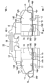
Fig. 1 is the front elevation of the disk type braker of the embodiment of the invention;
Fig. 2 is the planimetric map of disk type braker shown in Figure 1;
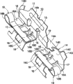
Fig. 3 is the stereogram that the piece spring that screws in side is represented as monomer;
Fig. 4 is the front elevation of piece spring shown in Figure 3;
Fig. 5 is the profile of the piece spring that arrow V-V direction is seen from Fig. 4;
Fig. 6 is the sectional drawing of the piece spring that arrow VI-VI direction is seen from Fig. 4;
Fig. 7 is that the ear that is illustrated in brake pad makes radially afterburning portion bend to the front elevation of the piece spring of the state on the lower panel;
Fig. 8 is the profile of the piece spring that arrow VIII-VIII direction is seen from Fig. 7;
Fig. 9 is the sectional drawing of the piece spring that arrow IX-IX direction is seen from Fig. 7;
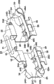
Figure 10 is the stereogram of piece spring shown in Figure 7;
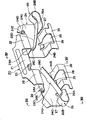
Figure 11 is the stereogram of the piece spring seen from the angle different with Figure 10;
Figure 12 is the stereogram that the piece spring that screws out side is represented as monomer;
Figure 13 is the profile of the piece spring that arrow XIII-XIII direction is seen from Figure 12;
Figure 14 is the sectional drawing of the piece spring that arrow XIV-XIV direction is seen from Figure 12;
Figure 15 is that expression makes radially afterburning portion among Figure 12 bend to the stereogram of the piece spring of the state on the lower panel;
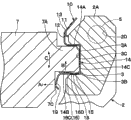
Figure 16 is the piece spring of the wrist that is installed on assembly that arrow XVI-XVI direction is seen from Fig. 2 and the amplification profile of brake pad;
The fragmentary cross-sectional view of the state when Figure 17 is the brake pad vibration of amplifying among expression Figure 16;
Figure 18 is a fragmentary cross-sectional view of representing the piece spring of variation in the position identical with Figure 17.
Description of symbols
1 dish; 2 assemblys; The 2A wrist; 3 guides; 3A upside wall; 3B downside wall; 4 brake caliperss; 5 sliding pins; 7 brake pads; 7A, 7B ear (protuberance); The smooth face of 7C; 10 screw in the lateral mass spring; 14 guiding boards; The 14A top plate; The 14B lower panel; The 14C baffle plate; 15 claws; 16 radially afterburning portions; The 16B return portion; 16C gusset portion; 16D, 16D ' projection piece; 17 otch; 18 gap parts; 19 sense of rotation reinforcing portions; 20 screw out the lateral mass spring.
Embodiment
Below, according to the disk type braker of the accompanying drawing detailed description embodiment of the invention.
Wherein, Fig. 1~Figure 17 represents the first embodiment of the present invention.Among the figure, the dish of 1 expression rotation, this dish 1 are when for example the vehicle forward direction is travelled, with the arrow A direction rotation of wheel (not shown) in Fig. 1.
The 2nd, be installed on the assembly as carriage of the nonrotational part of vehicle, as shown in Figure 1 and Figure 2, this assembly 2 is made of a pair of wrist 2A, 2A and joint 2B etc., wherein, a pair of wrist leaves the sense of rotation (circumferentially) of dish 1, to extending axially, joint connects the terminal side of this each wrist 2A and is provided with across the periphery of dish 1, is fixed on the non-rotating part of above-mentioned vehicle in the position of the inboard that becomes dish 1.
And, on assembly 2, being formed with the interconnective reinforcement 2C of the forward end of wrist 2A, 2A, this reinforcement forms arciform.In addition, on each wrist 2A, as shown in phantom in Figure 16, be respectively arranged with pin-and-hole 2D, in these pin-and-holes 2D, slidably embed sliding pin 5 described later.
In addition, be formed with the dish track portion (not shown) of extending at the length direction of wrist 2A (dish 1 axially) intermediate portion, and (coil 1 axial both sides) is formed with the piece guide 3 in inboard described later, the outside respectively in the both sides of this dish track portion along the periphery (rotating locus) of dish 1 circular-arcly.
3,3... is the piece guide of being located at respectively on each wrist 2A of assembly 2, and these piece guides 3 as Fig. 1 and shown in Figure 16, form the groove of cross section コ shape, extends to the direction of brake pad 7 slip displacements described later (dish 1 axially).And these piece guides 3 are positioned at the axial both sides of above-mentioned dish track portion, are equipped on terminal side (inboard) and the forward end (outside) of each wrist 2A respectively.In addition, in Fig. 1 and Figure 16, only represent the piece guide 3 in the outside, omitted inboard piece guide 3.
Wherein, piece guide 3, as shown in figure 16, by by the external diameter wall (below be called upside wall 3A) of dish 1 radial outside, the depth side wall surface 3C formation that links in the depth side by the internal diameter wall of dish 1 radially inner side (below be called downside wall 3B), with these walls 3A, 3B.And piece guide 3 constitutes cross section コ shape by these walls 3A, 3B, 3C, and upside wall 3A and downside wall 3B are separated up and down in Figure 16, in parallel to each other configuration.
That is, piece guide 3 forms between upside wall 3A and downside wall 3B from upper and lower and clips the 7A of ear, the 7B of brake pad 7 described later to (dish 1 is radially), between these walls 3A, 3B along the axial lead brake pad 7 of dish 1.In addition, the depth side wall surface 3C of piece guide 3 works as the so-called torque portion of bearing, and when brake operating, brake pad 7 bears from coiling 1 retarding torque that is subjected to by the 7A of ear described later, 7B.
The 4th, be located at the brake calipers on the assembly 2 slidably, as shown in Figure 1 and Figure 2, this brake calipers 4 is by constituting as the bottom: the interior 4A of foot, it is located at a side (inboard) of dish 1; The 4B of bridge portion, it extends to dish 1 opposite side (outside) from the interior 4A of foot, between each wrist 2A of assembly 2 across the periphery of dish 1; The outer 4C of foot, it extends to the inside direction in the footpath of dish 1 from forward end (outside) of the 4B of this bridge portion, and it is two forked that forward end constitutes.
And, on the interior 4A of foot of brake calipers 4, be formed with the cylinder (all not shown) that embeds piston slidably.In addition, a pair of assembly department 4D, the 4D of on the interior 4A of foot, be provided with among Fig. 2 left, right is outstanding, this each assembly department 4D is bearing on each wrist 2A of assembly 2 slidably by sliding pin 5 described later.
5, the 5th, brake calipers 4 is bearing in the sliding pin as support unit on the assembly 2 slidably, these sliding pins 5 use bolt 6 grades to be attached on each assembly department 4D of brake calipers 4 respectively, and its forward end is extended in each wrist 2B of assembly 2.And the forward end of each sliding pin 5 embeds in each pin-and-hole 2D of assembly 2 as shown in phantom in Figure 16 slidably, and brake calipers 4 is bearing on each wrist 2A of assembly 2 slidably by these sliding pins 5.
7, the 7th, be disposed at the inboard on the two sides of dish 1, the brake pad in the outside relatively, these brake pads 7 constitute the tabular friction means that extends along the sense of rotation of dish 1 as Fig. 1, Fig. 3 and shown in Figure 16.And, in the back side (inboard) of brake pad 7, be equipped with the 7A of ear, 7B as protuberance in its length direction (dish 1 circumferentially) both end sides.
At this moment, the 7A of ear, the 7B of brake pad 7 are for example shown in Figure 16, constitute identical shapedly mutually, left and rightly form symmetrically.But 7A of ear is configured in to the sense of rotation inlet side of the dish 1 of arrow A direction rotation (below be called screw in side), and the 7B of another ear is configured in the sense of rotation outlet side (below be called screw out side) of dish 1.
Wherein, the 7A of ear, the 7B of brake pad 7 embed respectively in the piece guide 3 of assembly 2 slidably by the guiding board 14,24 of described later spring 10,20.And the brake pad 7 in inboard, the outside is braked pincers 4 by the two sides that is pressed in dish 1 when carrying out brake operating, and at this moment, the 7A of ear, 7B are along the endwisely slip displacement of piece guide 3 to dish 1.
In addition, on brake pad 7, (the screw-in side of dish 1, back-out side) forms smooth facial 7C, 7D in its length direction both sides, and these smooth facial 7C, 7D extend to the inside direction in the footpath of dish 1 on the direction of the projected direction approximate vertical of the relative 7A of ear, 7B.And, in smooth facial 7C, the 7D of brake pad 7, on the smooth facial 7C of the screw-in side that is positioned at dish 1, sense of rotation reinforcing portion 19 and its Elastic Contact of described later spring 10, thus, brake pad 7 is all the time to sense of rotation (arrow A 1 direction among Figure 16) reinforcing of coiling 1.
On the other hand, be positioned at the 7B of ear of the back-out side of dish 1, the active force in the time of thus flexibly is pressed against on the depth side wall surface 3C of piece guide 3 by the baffle plate 24C of described later spring 20.And, when carrying out brake operating, utilize brake pad 7 from coiling 1 retarding torque that is subjected to (rotating torques of arrow A direction), make the 7B of ear that screws out side contact the retarding torque when between both surface of contact, bearing brake operating with depth side wall surface 3C by baffle plate 24C.
The 10th, be disposed at the screw-in lateral mass spring of dish 1 screw-in side, this piece spring 10 is installed on and is positioned in each wrist 2A of assembly 2 on the wrist 2A that screws in side, and back-out lateral mass spring 20 described later between the brake pad 7 in yielding support inboard, the outside, simultaneously, make the slip displacement of these brake pads 7 smooth and easy.
And, piece spring 10 is by methods such as punch process rubber-like corrosion resistant plates, crooked and integrally formed as Fig. 3~as shown in Figure 11, constitute by connection board 11 described later, guiding board 14,14, radially afterburning portion 16,16 and sense of rotation reinforcing portion 19,19 etc.
The 11st, the binding board of board 14 grades that respectively lead of linking block spring 10, this binding board 11 forms to extending axially across the periphery edge of dish 1, in its length direction both end sides, is formed with pair of plates portion 12,12 to the inside direction extension in the footpath of dish 1.And, link board 11 and bend to roughly " ㄑ " shape, along the wrist 2A inner side surface configuration of assembly 2 with respect to plat part 12 bending laterally.
In addition, at the length direction intermediate portion that links board 11, as Fig. 3~shown in Figure 6, be formed with downward-sloping extension, and with respect to linking the engaging board 13 that board 11 bends to roughly " ㄑ " shape, this engaging board 13 engages with the dish track portion of above-mentioned wrist 2A and installs from radially inner side, thus, with piece spring 10 with respect to the wrist 2A of assembly 2 dish 1 axially on the location.
14, the 14th, be located at the guiding board of engaging board 11 both end sides by each plat part 12, this guiding board 14 bends to roughly by the forward end (lower end side shown in Figure 3) from plat part 12 that コ shape forms.And, the guiding board 14 of these guiding in boards 14,14, chimeric as shown in figure 16 and be installed in the piece guide 3 in the outside, another guiding board 14 is chimeric and be installed in the inboard piece guide (not shown).
At this, the guiding board 14 of piece spring 10 as shown in figure 16, by constituting with the upside wall 3A of piece guide 3, top plate 14A, the lower panel 14B relative with the baffle plate 14C that links between these top plates 14A, the lower panel 14B and contact with the depth side wall surface 3C of piece guide 3 with downside wall 3B.And this baffle plate 14C forms the tabular body than the width of top plate 14A, lower panel 14B wideer (the axial width at dish 1 is wideer), is formed with the 16A of hyoplastron portion of radially afterburning portion 16 described later respectively in these width direction both sides.
In addition, on baffle plate 14C, the 14C of guiding board 14, forming the curved tabs 14D of portion, 14D than top plate 14A to the bight of the more outstanding upside of width direction (dish 1 axially), the 14D of these curved tabs portions is with respect to baffle plate 14C bending obliquely.In addition, on top plate 14A, the 14A of guiding board 14, outstanding and be formed with the 14E of calvus portion, 14E to its width direction (dish 1 axially).And, the 14E of these calvus portions with the 7A of ear of brake pad 7 during to 10 assemblings of piece spring as guide function.
15, the 15th, be located at the lower panel 14B of the board 14 that respectively leads and the claw between the baffle plate 14C, this each claw 15 forms the roughly U-shaped of giving prominence to from the lower end side of baffle plate 14C as shown in Figure 3 in gap part 18 described later as calvus.And claw 15 is embedded in the piece guide 3 the downside wall 3B Elastic Contact of its forward end and piece guide 3 with guiding board 14 shown in Figure 16,17.
Thus, claw 15 is when fastening under the state of its front end in resiliently deformable is on the downside wall 3B of piece guide 3 (wall of the radially inner side of dish 1), to the lead top plate 14A of board 14 of reaction force in the time of thus pushes to the upside wall 3A of piece 3 elasticity, make top plate 14A contact (face contact) with upside wall 3A, make the lower panel 14B of guiding board 14 leave micro-gap simultaneously, make guiding board 14 in piece guide 3, keep the state of anticreep from the downside wall 3B of piece guide 3.
16, the 16th, to the radially afterburning portion of brake pad 7,7 towards the radial outside reinforcing of dish 1, should each radially afterburning portion 16 by the integrally formed return portion 16B of the 16A of hyoplastron portion, terminal side and the 16A of this hyoplastron portion, reach the 16C of gusset portion etc. and constitute, wherein, the 16A of hyoplastron portion compares the position that becomes in width direction (dish 1 the axially) outside with the lower panel 14B of guiding board 14, with lower panel 14B almost parallel, outstanding from plate washer 14C.
At this, the return portion 16B of radially afterburning portion 16 and the 16C of gusset portion form width direction side (with the end of otch 17 opposite sides described later) from the 16A of hyoplastron portion to dish 1 axially extended elongated plate-like body, by making its terminal side turn back roughly U-shaped or roughly C shape, return portion 16B is formed as circular-arc curved part to the radial outside of dish 1.
In addition, the 16C of gusset portion forms from the forward end of the return portion 16B reed to the elongated plate-like of the radial outside diagonally extending of dish 1, and its forward end constitutes free end, extends to the top position of the lower panel 14B of guiding board 14.And the 16C of gusset portion of radially afterburning portion 16 such as Fig. 7, shown in Figure 16 in the time of in the 7A of ear with brake pad 7 packs guiding board 14 into, make its elastic bending deflection, push (with reference to Fig. 7~Figure 11) with the direction to the lower panel 14B of the board 14 that leads.
Thus, the 16C of gusset portion that makes radially afterburning portion 16 between the 7A of ear of the lower panel 14B of guiding board 14 and brake pad 7 to the configuration that extends axially of dish 1, elastic reactance in the time of thus is to the 7A of ear of brake pad 7 radial outside towards dish 1, arrow B direction reinforcing in Figure 16.
And the 7A of ear of brake pad 7 is pushed top plate 14A (the upside wall 3A of piece guide 3) to guiding board 14 by the active force (elastic reactance) of radially afterburning portion 16 by elasticity.Thus, the 7A of ear that has suppressed brake pad 7 arrow B direction in Figure 16 etc. in piece guide 3 (guiding board 14) is become flexible.
In addition, be formed with the projection piece 16D that bends to roughly " ㄑ " shape at its length direction midway on the 16C of gusset portion of radially afterburning portion 16, this projection piece 16D forms as the tab of bending to the inside direction in footpath of dish 1.And this projection piece 16D such as Fig. 7, Fig. 9~shown in Figure 11 are configured on the position with gap part described later 18 corresponding (relative).
Thus, as described later, in the 16C of gusset portion of radially afterburning portion 16 direction near the lower panel 14B of guiding board 14, promptly when dish 1 radially inner side displacement, as shown in figure 17, the downside wall 3B Elastic Contact of projection piece 16D and piece guide 3, the 16C of gusset portion of radially afterburning portion 16 can not contact with lower panel 14B, thereby has prevented excessive stress of effect such as lower panel 14B.
17, the 17th, be located at the slot-shaped otch between the 16A of hyoplastron portion of guiding lower panel 14B of board 14 and radially afterburning portion 16, these otch 17 following formation make the lower panel 14B that is disposed on the roughly the same plane and the 16A of hyoplastron portion disconnect mutually at its width direction (dish 1 axially).
And otch 17 has suppressed for example distortion of radially afterburning portion 16 influences such as the lower panel 14B of board 14 and sense of rotation reinforcing described later portion 19 of leading, and has to make the separate and function of resiliently deformable of radially afterburning portion 16 and sense of rotation reinforcing portion 19.
18, the 18th, be formed at the gap part on the lower panel 14B etc. of guiding board 14, these gap parts 18 as shown in Figure 3, form roughly OBL opening (cutting the hole), one side (the baffle plate 14C side of guiding board 14) constitutes thin slot-shaped extension in the position of the both sides that become claw 15.In addition, the opposite side of gap part 18 constitute wide cut コ shape, extend to the half-way of sense of rotation reinforcing described later portion 19.
And, gap part 18 is as Fig. 7, Fig. 9~shown in Figure 11, be configured on the position with the projection piece 16D corresponding (relative) of radially afterburning portion 16, when the 16C of gusset portion of radially afterburning portion 16 direction to the lower panel 14B of guiding board 14, promptly when dish 1 radially inner side displacement, as shown in figure 17, allow that projection piece 16D contacts with the downside wall 3B of piece guide 3.In addition,, the rigidity of lower panel 14B can be changed, thus, the elastic force (active force) of sense of rotation reinforcing described later portion 19 can be adjusted by the size of this gap part 18 of suitable adjustment.
19, the 19th, to the sense of rotation reinforcing portion of brake pad 7,7 to the sense of rotation reinforcing of dish 1, this sense of rotation reinforcing portion 19 is as Fig. 3~shown in Figure 11, form the wideer tabular body of width of lower panel 14B, from the front end oblique bending of lower panel 14B radially inner side to dish 1 than guiding board 14.In addition, though the width direction size of sense of rotation reinforcing portion 19 brake pad 7 when bringing into use to may wear to when last, as described later, also can obtain the enough length of the smooth facial 7C Elastic Contact of enough and brake pad 7.
And sense of rotation reinforcing portion 19 forms the reed of tabular body that bends to the wide cut of " ㄑ " shape in its width direction total length, and this crooked position such as Figure 16, shown in Figure 17 are with the smooth facial 7C Elastic Contact of brake pad.Thus, the smooth facial 7C of 19 pairs of brake pads 7 of sense of rotation reinforcing portion to dish 1 the roughly corresponding arrow A 1 direction reinforcing of sense of rotation (the arrow A direction among Figure 16).And the active force of this moment is also given by the lower panel 14B of the board 14 that leads when being given by sense of rotation reinforcing portion 19.In addition, as mentioned above, separate micro-gap by the lower panel 14B that makes guiding board 14 from the downside wall 3B of piece guide 3, lower panel 14B is worked as elastic member on the circumferential total length of dish, thus, can be to its suitable adjustment, so that the elastic force (active force) of sense of rotation reinforcing portion 19 can be not strong excessively.
The 20th, be disposed at the piece spring of the back-out side of dish 1 back-out side, this piece spring 20 is installed on and is positioned in each wrist 2A of assembly 2 on the wrist 2A that screws out side, and the piece spring 10 of above-mentioned screw-in side between in the brake pad 7 in yielding support inboard, the outside, make the slip displacement of these brake pads 7 smooth and easy.
And the piece spring 20 that screws out side be the structure roughly the same with the piece spring 10 of above-mentioned screw-in side, as Figure 12~shown in Figure 15, by binding board 21; Plat part 22,22; Engaging board 23; Guiding board 24,24; Claw 25,25; Radially afterburning portion 26,26; Formations such as otch 27,27 and gap part 28,28.
But the piece spring 20 that screws out side is compared with the piece spring 10 that screws in side, does not have sense of rotation reinforcing portion 19,19, the substitute is to be formed with warpage board 29,29.That is, this warpage board 29 forms the wideer tabular body of width than the lower panel 24B of guiding board 24 described later, generally perpendicularly different with sense of rotation reinforcing portion 19 on the warpage this point to the radially inner side of dish 1 from the front end of lower panel 14B.
In addition, screw out in the piece spring 20 of side, guiding board 24 is made of top plate 24A, lower panel 24B, baffle plate 24C, the 24D of curved tabs portion and the 14E of calvus portion etc.And radially afterburning portion 26 is made of the 26A of hyoplastron portion, return portion 26B, the 26C of gusset portion and projection piece 26D.
And, the piece spring 20 that screws out side as shown in figure 16, warpage board 29 is configured to the state that leaves all the time from the smooth facial 7D of brake pad 7, allows that brake pad 7 is threaded into the sense of rotation reinforcing portion 19 of piece spring 10 of side to arrow A 1 direction reinforcing.
The disk type braker of present embodiment has structure as described above, secondly, its action is described.
At first,,, make piston, thus, the brake pad 7 of inboard is pressed onto on the side of dish 1 towards dish 1 slip displacement by to the interior 4A of foot (cylinder) of brake calipers 4 supply system hydrodynamic pressure carrying out vehicle braked when operation.And, at this moment and since brake calipers 4 be subjected to from dish 1 push reaction force, so brake calipers 4 integral body with respect to the wrist 2A of assembly 2 displacement of sliding to the inside, the outer 4C of foot is pressed onto the brake pad 7 in the outside and coils on 1 the another side.
Thus, but brake pad 7 betweens in inboard and the outside can give this and coil 1 braking force from the axial both sides powerful ground clamping dish 1 that the arrow A direction is rotated to Fig. 1, Figure 16.And, when brake operating is removed,, the brake pad 7 in inboard and the outside is left from coiling 1 by stopping hydraulic pressure supply to above-mentioned piston, return to non-braking state once more.
In addition, when carrying out such brake operating, releasing (during non-braking), to the 1 direction reinforcing of Figure 16 arrow A, brake pad 7 is all the time to sense of rotation (circumferentially) the quilt reinforcing of dish 1 by the sense of rotation reinforcing portion 19 of piece spring 10 for the tabular surface 7C that is arranged in dish 1 screw-in side in smooth facial 7C, the 7D of brake pad 7.And, being positioned at the active force of the 7B of ear of dish 1 back-out side by this moment, the baffle plate 24C by piece spring 20 flexibly is pressed against on the depth side wall surface 3C of piece guide 3.At this moment, the active force of sense of rotation reinforcing portion 19 when brake pad is brand-new and wearing and tearing the time be roughly constantly, big change does not appear and can not resemble the prior art.
Therefore, can be by being located at sense of rotation reinforcing portion 19 limiting friction pieces 7 on the piece spring 10 that screws in side because the vibration during vehicle driving etc. and circumferentially becoming flexible at dish 1.And, when carrying out brake operating, brake pad 7 is subjected to the retarding torque (rotating torques of arrow A direction) from dish 1, at this moment, continue to contact with depth side wall surface 3C by baffle plate 24C owing to screw out the 7B of ear of side, so can be by the retarding torque of wrist 2A (depth side wall surface 3C) when bearing brake operating that screws out side.
In addition, the guiding board 14,24 of the 7A of ear, the 7B of brake pad 7 by piece spring 10,20 embeds the screw-in side that is positioned at dish 1, the piece guide 3,3 that screws out side slidably, by the 16C of gusset portion, the 26C etc. of radially afterburning portion 16,26 with its arrow B, the reinforcing of B direction in Figure 16.Thus, the 7A of ear, the 7B of brake pad 7 can be elastically pressed onto on top plate 14A, the 24A of guiding board 14,24.
Therefore, can be by radially afterburning portion 16, the 26 limiting friction pieces 7 of piece spring 10,20 because the vibration during vehicle driving etc. and radially loosening at dish 1.And, when carrying out brake operating, make on one side the 7A of ear, the 7B of brake pad 7 remain on and lead the top plate 14A of board 14,24, the state that 24A slips, on one side can with the brake pad 7 in inboard, the outside to guiding board 14,24 swimmingly positioning disk 1 axially.
At this, with the piece spring 10 that is positioned at dish 1 screw-in side is example, this radially afterburning portion 16 is made of the 16A of hyoplastron portion, return portion 16B and the 16C of gusset portion etc., the 16C of this gusset portion is owing to form as the reed of elongated plate-like, so can suppress excessive to the active force of the 7A of ear arrow B direction reinforcing in Figure 16 of brake pad 7.
But, when carrying out the vehicle braked operation etc., owing to act on the brake pad 7 from the braking torque of dish 1, thereby the arrow C direction vibration of brake pad 7 in Figure 17.Therefore, the 7A of ear of brake pad 7 with the 16C of gusset portion of radially afterburning portion 16 press to towards the approaching direction of lower panel 14B of guiding board 14 (with the side of arrow B in the opposite direction), the 16C of gusset portion of radially afterburning portion 16 contacts with the lower panel 14B of guiding board 14, produces excessive stress in this lower panel 14B and sense of rotation reinforcing portion 19.Particularly because the lower panel 14B of guiding board 14 utilizes claw 15 to leave micro-gap from the downside wall 3B of piece guide 3, so under the most bad situation, baffle plate 14C that stress is concentrated and the attachment portion of lower panel 14B may be damaged.
Therefore, according to present embodiment, take following structure, on the 16C of gusset portion of radially afterburning portion 16, form from its length direction midway the position warpage to the projection piece 16D of the inside direction in footpath of dish 1, with this projection piece 16D be configured in the lower panel 14B that is formed at guiding board 14 etc. on the position of gap part 18 corresponding (relative) on.
Thus, when carrying out the vehicle braked operation, because the influence of braking torque etc., brake pad 7 is the vibration of arrow C direction in Figure 17, even make its radially inner side displacement towards dish 1, so that the 16C of gusset portion of radially afterburning portion 16 is near the lower panel 14B of guiding board 14, also can make the downside wall 3B Elastic Contact of projection piece 16D and piece guide 3, and the 16C of gusset portion of radially afterburning portion 16 can not contact with lower panel 14B, thereby can prevent below the excessive stress of effect on the plate 14B and sense of rotation reinforcing portion 19.
Like this, the projection piece 16D that is formed on the 16C of gusset portion of radially afterburning portion 16 contacts with the downside wall 3B of piece guide 3, can bear the external force of following arrow C direction vibration etc., act on excessive stress in lower panel 14B that can prevent and the sense of rotation reinforcing portion 19 at guiding board 14.
Therefore, the radially afterburning portion 16 of piece spring 10, as mentioned above, when producing vibration, the lower panel 14B that can utilize projection piece 16D to prevent that the 16C of gusset portion from overlapping guiding board 14 powerfully goes up and is out of shape, and can make the raisings such as durability, life-span of piece spring 10 integral body, and can improve reliability.
In addition, the effect of the projection piece 16D of relevant above-described screw-in lateral mass spring 10, concerning the projection piece 26D that screws out lateral mass spring 20 also is identical, the projection piece 26D that is formed on the 26C of gusset portion of radially afterburning portion 26 contacts with the downside wall 3B of piece guide 3, the rightabout external force of arrow B direction among Figure 16 of vibration etc. can be born and follow, and the excessive stress of effect on the lower panel 24B of guiding board 24 can be prevented.
In addition, according to present embodiment, in pair of block spring 10,20, be positioned on the piece spring 10 that coils 1 screw-in side and sense of rotation reinforcing portion 19 be set with guiding board 14, radially afterburning portion 16, this sense of rotation reinforcing portion 19 is following structure, for to brake pad 7 to dish 1 sense of rotation reinforcing, and form from the lower panel 14B inclination warpage of guiding board 14 tabular body to the wide cut of the radially inner side of dish 1.
Therefore, compared with prior art, the active force (spring load) of sense of rotation reinforcing portion 19 can be increased ground and set, and can continue the smooth facial 7C of brake pad 7 powerfully to sense of rotation (arrow A 1 direction among Figure 16) reinforcing of coiling 1.And, since can make this moment add force direction with the direction of dish 1 plane almost parallel on be orientated, so can prevent that the brake pad 7 in inboard, the outside is with respect to dish 1 inclination.
Therefore, smooth facial 7C by using such 19 pairs of brake pads 7 of sense of rotation reinforcing portion is in sense of rotation (arrow A 1 direction among Figure 16) reinforcing of dish 1, can make brake pad 7 with respect to dish 1 attitude stabilization, and can keep the sliding properties etc. of the brake pad 7 in inboard, the outside well.
In addition, sense of rotation reinforcing portion 19 since from the lower panel 14B of guiding board 14 to the radially inner side of dish 1 warpage obliquely, so in the time of on the wrist 2A that piece spring 10 is assembled into assembly 2, when brake pad 7 is assembled on piece spring 10, sense of rotation reinforcing portion 19 can not constitute obstacle, operability in the time of can improving assembling simultaneously, can prevent that the active force of sense of rotation reinforcing portion 19 in assembly operation from changing.
In addition, as mentioned above, by the radially afterburning portion 16 that on piece spring 10, is provided with and sense of rotation reinforcing portion 19 can inhibition dish 1 radially, the becoming flexible of the brake pad 7 of sense of rotation, and can suppress the vibration of brake pad 7 well, simultaneously, the generation that can prevent that break from ringing etc.
On the other hand, owing on the piece spring 10 of the screw-in side that is positioned at dish 1, be provided with the claw 15 that is entrenched in the piece guide 3 of assembly 2 with the board 14 that leads, therefore, by making the downside wall 3B Elastic Contact of this claw 15 and piece guide 3, the guiding board 14 relative piece guides 3 of piece spring 10 are pressed to the radial outside of dish 1, the lower panel 14B of guiding board 14 is left from the downside wall 3B of piece guide 3, and stably produce the active force of sense of rotation reinforcing portion 19, simultaneously, can make the guiding board 14 of piece spring 10 keep the anticreep state, and can make the assembling attitude stabilization of each wrist 2A of piece spring 10 relative assemblys 2 with respect to piece guide 3.
In addition, because on piece spring 10, between the 16A of hyoplastron portion of guiding lower panel 14B of board 14 and radially afterburning portion 16, be formed with slot-shaped otch 17, therefore, can make radially afterburning portion 16 and sense of rotation reinforcing portion 19 resiliently deformable independently of each other, can prevent that for example the distortion of radially afterburning portion 16 is exerted one's influence to sense of rotation reinforcing portion 19.
Therefore, can prevent in radially afterburning portion 16 and sense of rotation reinforcing portion 19 stress that effect is unnecessary, and the generation that can suppress that stress is concentrated etc.And, can make radially afterburning portion 16 and sense of rotation reinforcing portion 19 separate for the active force of brake pad 7, make the attitude stabilization of piece.
In addition, in the above-described embodiments, so that the projection piece 16D that is formed on the 16C of gusset portion of radially afterburning portion 16 is that example is illustrated towards the situation of the structure of for example coiling 1 radially inner side (downside among Figure 17) oblique bending.But, the invention is not restricted to this, variation for example shown in Figure 180 also can be for bending to projection piece 16D ' roughly U-shaped or the roughly structure of V-arrangement.
That is, the projection piece 16D ' in the variation is owing to be the downside wall 3B contacting structure of its convex side and piece guide 3, so can limit on the lower panel 14B that the 16C of gusset portion is overlapped in the board 14 that leads and be out of shape powerfully.And, concerning screwing out the piece spring 20 of side, also can carry out the distortion identical with projection piece 16D '.
In addition, in the above-described embodiments, be the structure that projection piece 16D is configured in the position corresponding with gap part 18.But, be that the 16C of gusset portion that makes radially afterburning portion 16 does not directly contact with the lower panel 14B of guiding board 14 and is provided with owing to this projection piece 16D, for example also can be projection piece 16D touches the structure on the claw 15.
In the above-described embodiments, as Figure 12~shown in Figure 15, with by linking board 21; Plat part 22,22; Engaging board 23; Guiding board 24,24; Claw 25,25; Radially afterburning portion 26,26; The situation that formations such as otch 27,27 and gap part 28,28 screw out the piece spring 20 of side is that example is illustrated.But, the invention is not restricted to this, for example also can make projection piece 26D is the projection piece 16D ' of variation shown in Figure 180, or make projection piece 26D for claw 25 on contacting structure.In addition, also can as opening the disk type braker that flat 5-89978 communique put down in writing, the reality of enumerating in the prior art constitute the piece spring that screws out side.
In addition, in the above-described embodiments, the situation of コ shape is that example is illustrated so that piece spring 10,20 forms roughly across the periphery of coiling 1.But, the invention is not restricted to this, also can be following structure, for example will have two piece springs in the shape of incision such as neutral position that link board 11,21 and be configured in respectively and coil 1 inboard, the outside and constitute piece spring 10,20.
Claims (10)
1, a kind of disk type braker, it is by constituting as lower member: assembly, its have on the sense of rotation of dish, leave and axially across a pair of wrist of the outer circumferential side of this dish, and on this each wrist, be provided with the piece guide; Brake calipers, it is located on each wrist of this assembly slidably; A pair of brake pad, it is slidably mounted on each wrist of described assembly by described guide, and is pressed into by this brake calipers on the two sides of dish; And the pair of block spring, it is installed on each wrist side of described assembly respectively, and between each wrist this each brake pad of yielding support; It is characterized in that,
A piece spring in the described pair of block spring is following structure, and it has: the guiding board, it is chimeric and be installed on the piece guide of described assembly, with this piece guide at the described brake pad of axial lead; Radially afterburning portion, it is to the radially reinforcing of described brake pad to dish; And sense of rotation reinforcing portion, it forms from described guiding board to the radially inner side inclination warpage of dish and by the tabular body of the flexibly mounted wide cut of this joggling part, one side contacts of this tabular body and described brake pad is also afterburning on the sense of rotation of dish to described brake pad, with the opposite side of described brake pad all the time by on another piece spring that is pressed in the described pair of block spring.
2, disk type braker as claimed in claim 1, it is following structure, described spring is provided with described guiding board and is embedded in claw on the piece guide of described assembly, this claw by with the wall Elastic Contact of the radially inner side of the dish of described guide, and to of the radial outside reinforcing of the relative piece guide of described guiding board to dish.
3, disk type braker as claimed in claim 2, it is following structure: described radially afterburning portion is formed in the mode of extending along the axle direction that coils between this guiding board and brake pad, and to of the radial outside reinforcing of described brake pad to dish, at projection piece from the length direction of described radially afterburning portion to the inside direction warpage in footpath of dish is set midway, be provided with on the described guiding board when described radially afterburning portion towards the radially inner side displacement of dish and when leading board, allow the gap part that described projection piece contacts with the side surface side of piece guide.
4, as claim 1,2 or 3 described disk type brakers, wherein, it is free end axially extended elongated plate-like body along dish between described guiding board and brake pad towards the radial outside warpage of dish for roughly U-shaped, its forward end that described radially afterburning portion forms its terminal side, and is formed with between described radially afterburning portion and guiding board and is used to make described sense of rotation reinforcing portion and radially afterburning portion is separate and the otch of resiliently deformable.
5, disk type braker as claimed in claim 1 is characterized in that, a piece spring in the described pair of block spring is mounted in the screw-in lateral mass spring on the wrist of the screw-in side that is positioned at dish in each wrist of described assembly.
6, as each the described disk type braker in the claim 1,2,3 or 5, it is characterized in that, the width direction size of described sense of rotation reinforcing portion forms, though described brake pad when bringing into use to may wear to when last also can with the length of described brake pad Elastic Contact.
7, as each the described disk type braker in the claim 1,2,3 or 5, it is characterized in that, afterburning portion of described rotation and described joggling part different terrain become in its width direction total length and bend to " ㄑ " shape, this crooked position and described brake pad Elastic Contact.
As each the described disk type braker in the claim 1,2,3 or 5, it is characterized in that 8, under the free state of described sense of rotation reinforcing portion before the installation of described brake pad, the tabular body of described wide cut is actually parallel with respect to the axis of dish.
9, a kind of disk type braker, it is by constituting as lower member: assembly, its have on the sense of rotation of dish, leave and axially across a pair of wrist of the outer circumferential side of this dish, and on this each wrist, be provided with the piece guide; Brake calipers, it is located on this assembly slidably; A pair of brake pad, it is slidably mounted on each wrist of described assembly by described guide, and is pressed into by this brake calipers on the two sides of dish; And the pair of block spring, it is installed on each wrist side of described assembly respectively, and between each wrist this each brake pad of yielding support; It is characterized in that,
A piece spring in the described pair of block spring has: the guiding board, it is chimeric and be installed on the piece guide of described assembly, with this piece guide at the described brake pad of axial lead; And radially afterburning portion, it forms along extending axially of dish between this guiding board and brake pad, to of the radial outside reinforcing of described brake pad to dish,
Described spring is provided with described guiding board and is embedded in claw on the piece guide of described assembly, this claw by with the wall Elastic Contact of the radially inner side of the dish of described guide, and to the radial outside reinforcing of the relative piece guide of described guiding board to dish
At projection piece from the length direction of described radially afterburning portion to the inside direction warpage in footpath of dish is set midway, be provided with on the described guiding board when described radially afterburning portion towards the radially inner side displacement of dish and when leading board, allow the gap part that described projection piece contacts with the side surface side of piece guide.
10, disk type braker as claimed in claim 9, wherein, it is free end axially extended elongated plate-like body along dish between described guiding board and brake pad towards the radial outside warpage of dish for roughly U-shaped, its forward end that described radially afterburning portion forms its terminal side, and is formed with between described radially afterburning portion and guiding board and is used to make described sense of rotation reinforcing portion and radially afterburning portion is separate and the otch of resiliently deformable.
Applications Claiming Priority (2)
| Application Number | Priority Date | Filing Date | Title |
|---|---|---|---|
| JP132420/05 | 2005-04-28 | ||
| JP2005132420A JP4477540B2 (en) | 2005-04-28 | 2005-04-28 | Disc brake |
Publications (2)
| Publication Number | Publication Date |
|---|---|
| CN1854554A CN1854554A (en) | 2006-11-01 |
| CN100582520C true CN100582520C (en) | 2010-01-20 |
Family
ID=37085246
Family Applications (1)
| Application Number | Title | Priority Date | Filing Date |
|---|---|---|---|
| CN200610071470A Active CN100582520C (en) | 2005-04-28 | 2006-03-24 | Disc braker |
Country Status (4)
| Country | Link |
|---|---|
| US (2) | US7766131B2 (en) |
| JP (1) | JP4477540B2 (en) |
| CN (1) | CN100582520C (en) |
| DE (1) | DE102006019386A1 (en) |
Families Citing this family (39)
| Publication number | Priority date | Publication date | Assignee | Title |
|---|---|---|---|---|
| JP4740416B2 (en) * | 2007-05-31 | 2011-08-03 | 日立オートモティブシステムズ株式会社 | Disc brake |
| FR2927388B1 (en) * | 2008-02-11 | 2010-05-28 | Bosch Gmbh Robert | GUIDING A DISC BRAKE PAD HOLDER |
| JP5047200B2 (en) * | 2009-01-21 | 2012-10-10 | 日立オートモティブシステムズ株式会社 | Disc brake |
| DE102009022633A1 (en) * | 2009-03-25 | 2010-10-14 | Continental Teves Ag & Co. Ohg | Partial lining disc brake with a spring arrangement for Lüftspielverbesserung and spring arrangement |
| JP5137888B2 (en) * | 2009-03-26 | 2013-02-06 | 日信工業株式会社 | Vehicle disc brake |
| JP5277089B2 (en) * | 2009-06-30 | 2013-08-28 | 日立オートモティブシステムズ株式会社 | Disc brake |
| JP5213818B2 (en) * | 2009-09-01 | 2013-06-19 | 日信工業株式会社 | Vehicle disc brake |
| US8397880B2 (en) * | 2010-05-27 | 2013-03-19 | Akebono Brake Corporation | Pad retraction device |
| FR2969238B1 (en) * | 2010-12-17 | 2014-04-25 | Bosch Gmbh Robert | SINGLE GUIDING MEMBER OF A DISC BRAKE PATIN AND DISK BRAKE PROVIDED WITH SUCH GUIDING BODIES |
| US8393441B2 (en) | 2011-01-24 | 2013-03-12 | Akebono Brake Corporation | Spreader spring |
| US8376092B2 (en) * | 2011-02-10 | 2013-02-19 | Akebono Brake Corp. | Pad retraction device |
| JP5492176B2 (en) | 2011-11-30 | 2014-05-14 | 曙ブレーキ工業株式会社 | Caliper body, caliper body torque receiving part grooving method |
| FR2984440B1 (en) | 2011-12-15 | 2014-02-28 | Bosch Gmbh Robert | DISC BRAKE SLIDER SLIDE AND DISK BRAKE EQUIPPED WITH SUCH SLIDER |
| FR2984437B1 (en) | 2011-12-15 | 2014-01-17 | Bosch Gmbh Robert | LATCH GUIDING MEMBER OF A DISC BRAKE PATIN AND DISK BRAKE EQUIPPED WITH SUCH GUIDING BODIES |
| FR2984438B1 (en) * | 2011-12-15 | 2014-01-17 | Bosch Gmbh Robert | RADIAL SPRING OF DISC DISC BRAKE PAD AND BRAKE PADS AND BRAKES EQUIPPED WITH SUCH RADIAL SPRINGS |
| FR2984439B1 (en) | 2011-12-15 | 2014-06-27 | Bosch Gmbh Robert | SPRING BRAKE GUIDE SPRING GUIDE AND DISK BRAKE EQUIPPED WITH SUCH GUIDING BODIES |
| DE102012016737A1 (en) * | 2012-08-23 | 2014-02-27 | Lucas Automotive Gmbh | Disc brake for a motor vehicle with plastically deformable return spring and return spring |
| JP5988028B2 (en) * | 2012-09-19 | 2016-09-07 | 株式会社アドヴィックス | Disc brake and pad support |
| JP5858244B2 (en) * | 2013-04-25 | 2016-02-10 | 株式会社アドヴィックス | Disc brake device |
| FR3005127B1 (en) * | 2013-04-29 | 2015-04-17 | Chassis Brakes Int Bv | "BRAKE DISC BRAKE WITH STABILIZED BRAKES, AND ASSOCIATED METHODS OF ASSEMBLING AND REPLACING A SKATE" |
| FR3005334B1 (en) * | 2013-05-02 | 2015-04-24 | Chassis Brakes Int Bv | "DISC BRAKE COMPRISING A PRELOAD SPRING OF A BRAKE PAD" |
| US9279466B2 (en) * | 2013-07-22 | 2016-03-08 | Nissin Kogyo Co., Ltd. | Vehicle disc brake |
| US9267559B2 (en) * | 2013-09-25 | 2016-02-23 | Akebono Brake Industry Co., Ltd | Dampening clip |
| US9970495B2 (en) | 2014-08-01 | 2018-05-15 | Freni Brembo S.P.A. | Disc brake caliper employing a spring to influence pads acting on the disc of the disc brake |
| DE112015005221T5 (en) * | 2014-11-19 | 2017-08-24 | Hitachi Automotive Systems, Ltd. | disc brake |
| KR101628600B1 (en) * | 2015-01-06 | 2016-06-08 | 현대자동차주식회사 | Pad liner for reducing drag in brake caliper |
| KR101892925B1 (en) * | 2017-02-22 | 2018-08-29 | 주식회사 만도 | Pad spring |
| US11204071B2 (en) * | 2017-06-30 | 2021-12-21 | Hitachi Astemo, Ltd. | Disc brake |
| US11378146B2 (en) | 2017-07-11 | 2022-07-05 | Hitachi Astemo, Ltd. | Disc brake |
| DE102017007021A1 (en) * | 2017-07-25 | 2019-01-31 | Lucas Automotive Gmbh | Brake pad assembly for a vehicle brake |
| JP6958169B2 (en) * | 2017-09-22 | 2021-11-02 | 株式会社アドヴィックス | Disc brake device |
| JP6982493B2 (en) * | 2017-12-28 | 2021-12-17 | 曙ブレーキ工業株式会社 | Pad clips, pad clip and return spring assemblies, and floating disc brakes |
| IT201800006498A1 (en) * | 2018-06-20 | 2019-12-20 | SPRING FOR FRICTION PADS IN A DISC BRAKE CALIPER | |
| USD878260S1 (en) * | 2018-11-13 | 2020-03-17 | Preferred Tool & Die, Inc. | Brake caliper hardware |
| CN109296681A (en) * | 2018-12-10 | 2019-02-01 | 安徽江淮汽车集团股份有限公司 | Disc-like brake structure |
| KR102210465B1 (en) * | 2019-09-03 | 2021-01-29 | 현대모비스 주식회사 | Pad liner for braking apparatus |
| USD928674S1 (en) * | 2020-01-08 | 2021-08-24 | Preferred Tool & Die, Inc. | Brake caliper hardware |
| JP7356939B2 (en) * | 2020-03-19 | 2023-10-05 | 日立Astemo株式会社 | disc brake |
| DE102020125418B3 (en) | 2020-09-29 | 2022-03-03 | Schaeffler Technologies AG & Co. KG | Braking device for a vehicle, vehicle with the braking device and method for resetting a first braking partner of the braking device |
Family Cites Families (9)
| Publication number | Priority date | Publication date | Assignee | Title |
|---|---|---|---|---|
| GB2006357A (en) * | 1977-10-20 | 1979-05-02 | Girling Ltd | Pad Pin Providing Circumferential Biassing |
| JPS5910434Y2 (en) * | 1978-01-23 | 1984-04-02 | 住友電気工業株式会社 | Brake pad support device |
| JP2724757B2 (en) * | 1989-09-13 | 1998-03-09 | 曙ブレーキ工業株式会社 | Disc brake device |
| JP3191820B2 (en) | 1991-09-27 | 2001-07-23 | 東芝ライテック株式会社 | Discharge lamp lighting device and lighting equipment |
| JPH05280563A (en) * | 1992-03-31 | 1993-10-26 | Aisin Seiki Co Ltd | Disk brake |
| EP0732521B1 (en) * | 1995-03-16 | 2000-09-13 | Akebono Brake Industry Co., Ltd. | Pad clip for disc brake |
| JP2000161401A (en) * | 1998-11-26 | 2000-06-16 | Akebono Brake Ind Co Ltd | Pad clip for disc brake |
| CN100580268C (en) * | 2003-10-14 | 2010-01-13 | 株式会社爱德克斯 | Disk brake apparatus |
| JP4653010B2 (en) * | 2006-04-28 | 2011-03-16 | 日立オートモティブシステムズ株式会社 | Disc brake |
-
2005
- 2005-04-28 JP JP2005132420A patent/JP4477540B2/en active Active
-
2006
- 2006-03-24 CN CN200610071470A patent/CN100582520C/en active Active
- 2006-03-30 US US11/392,670 patent/US7766131B2/en active Active
- 2006-04-26 DE DE102006019386A patent/DE102006019386A1/en active Pending
-
2010
- 2010-02-23 US US12/710,694 patent/US8016083B2/en active Active
Also Published As
| Publication number | Publication date |
|---|---|
| DE102006019386A1 (en) | 2006-11-02 |
| JP2006308011A (en) | 2006-11-09 |
| US20100147635A1 (en) | 2010-06-17 |
| JP4477540B2 (en) | 2010-06-09 |
| US20060260884A1 (en) | 2006-11-23 |
| CN1854554A (en) | 2006-11-01 |
| US7766131B2 (en) | 2010-08-03 |
| US8016083B2 (en) | 2011-09-13 |
Similar Documents
| Publication | Publication Date | Title |
|---|---|---|
| CN100582520C (en) | Disc braker | |
| US6286636B1 (en) | Disc brake | |
| CN102032296B (en) | Disk type braker | |
| US6527090B1 (en) | Guiding spring for friction elements and disc brake comprising same | |
| US20100243385A1 (en) | Vehicle disk brake | |
| US8220595B2 (en) | Brake pad for a disc brake | |
| CN101063470B (en) | Disk brake | |
| CN106715945B (en) | Disk brake | |
| JPH08511081A (en) | Floating caliper type disc brake for automobile | |
| CN101825148A (en) | Disk type braker | |
| CN104235239A (en) | Vehivle disc brake | |
| KR20100102584A (en) | Brake lining for a spot-type disk brake | |
| JP2008501897A (en) | Disc brake with spring assembly | |
| GB2109065A (en) | Friction-pad wear-limit warning device for disc brakes | |
| WO2014199881A1 (en) | Disk brake for vehicle | |
| US4196794A (en) | Retaining plate for brake pads | |
| US6971486B2 (en) | Caliper spring clip with axial force direction | |
| CN105757148A (en) | Pad Liner For Reducing Drag In Brake Caliper Of Vehicle Brake | |
| EP1672239B1 (en) | Retention spring for brake pressure pads | |
| JP4335344B2 (en) | Disc brake | |
| CN103249960A (en) | Disc brake device | |
| CN110730876B (en) | Disc brake | |
| JP2008241046A (en) | Disc brake | |
| WO2018117234A1 (en) | Brake pad assembly and caliper | |
| JP2006336784A (en) | Vehicular disc brake |
Legal Events
| Date | Code | Title | Description |
|---|---|---|---|
| C06 | Publication | ||
| PB01 | Publication | ||
| C10 | Entry into substantive examination | ||
| SE01 | Entry into force of request for substantive examination | ||
| C14 | Grant of patent or utility model | ||
| GR01 | Patent grant |