CN100566081C - The motor of band brake and have the robot device of this motor - Google Patents
The motor of band brake and have the robot device of this motor Download PDFInfo
- Publication number
- CN100566081C CN100566081C CNB2007100800346A CN200710080034A CN100566081C CN 100566081 C CN100566081 C CN 100566081C CN B2007100800346 A CNB2007100800346 A CN B2007100800346A CN 200710080034 A CN200710080034 A CN 200710080034A CN 100566081 C CN100566081 C CN 100566081C
- Authority
- CN
- China
- Prior art keywords
- aforementioned
- pad
- brake
- motor
- keep plate
- Prior art date
- Legal status (The legal status is an assumption and is not a legal conclusion. Google has not performed a legal analysis and makes no representation as to the accuracy of the status listed.)
- Expired - Fee Related
Links
Images


Classifications
-
- H—ELECTRICITY
- H02—GENERATION; CONVERSION OR DISTRIBUTION OF ELECTRIC POWER
- H02K—DYNAMO-ELECTRIC MACHINES
- H02K7/00—Arrangements for handling mechanical energy structurally associated with dynamo-electric machines, e.g. structural association with mechanical driving motors or auxiliary dynamo-electric machines
- H02K7/10—Structural association with clutches, brakes, gears, pulleys or mechanical starters
- H02K7/102—Structural association with clutches, brakes, gears, pulleys or mechanical starters with friction brakes
-
- F—MECHANICAL ENGINEERING; LIGHTING; HEATING; WEAPONS; BLASTING
- F16—ENGINEERING ELEMENTS AND UNITS; GENERAL MEASURES FOR PRODUCING AND MAINTAINING EFFECTIVE FUNCTIONING OF MACHINES OR INSTALLATIONS; THERMAL INSULATION IN GENERAL
- F16D—COUPLINGS FOR TRANSMITTING ROTATION; CLUTCHES; BRAKES
- F16D59/00—Self-acting brakes, e.g. coming into operation at a predetermined speed
- F16D59/02—Self-acting brakes, e.g. coming into operation at a predetermined speed spring-loaded and adapted to be released by mechanical, fluid, or electromagnetic means
-
- H—ELECTRICITY
- H02—GENERATION; CONVERSION OR DISTRIBUTION OF ELECTRIC POWER
- H02K—DYNAMO-ELECTRIC MACHINES
- H02K15/00—Methods or apparatus specially adapted for manufacturing, assembling, maintaining or repairing of dynamo-electric machines
- H02K15/02—Methods or apparatus specially adapted for manufacturing, assembling, maintaining or repairing of dynamo-electric machines of stator or rotor bodies
- H02K15/03—Methods or apparatus specially adapted for manufacturing, assembling, maintaining or repairing of dynamo-electric machines of stator or rotor bodies having permanent magnets
Abstract
The invention provides a kind of when brake discharges keep plate can not contact pad band brake motor and use the robot device of this motor.Particularly, it is the distolateral brake portion that is provided with at rotating shaft, and brake portion comprise have the 1st pad and be arranged at the braking parts of fixed part, only be installed on sliding freely in the axial direction the keep plate of rotating shaft, the armature by having the 2nd pad to the 1st pad of braking parts 5 push keep plate brake spring, and attract the motor of armature with the band brake of the calutron of brake off, the a pair of spring support of the aforementioned keep plate of clamping is set in the end of rotating shaft 2, between keep plate and each spring support, disposes support spring simultaneously.
Description
Technical field
The present invention relates to the motor of band brake and have the robot device of this motor.
Background technology
For example use the motor of band brake to be used as drive motor in the industrial robot with respect to the rotating basis of fixed pedestal, perhaps with respect to the CD-ROM drive motor of the arm of rotating basis, also has CD-ROM drive motor (for example, with reference to patent documentation 1) with respect to the actuating arm of support arm.
Fig. 3 is the figure of the robot device A of the industrial robot in expression prior art (the present invention also uses) etc., rotatably is supported with rotating basis C on fixed pedestal B, rotatably is supported with upright arm D on aforementioned rotating basis C.In addition, on aforementioned upright arm D, rotatably be supported with horizontal arm E, rotatably be supported with wrist portion F in the top ends of aforementioned levels arm E.Each rotating parts uses the motor of band brake to be used as CD-ROM drive motor.
As shown in Figure 4, the motor of aforementioned band brake is one distolateral the rotating shaft 2 of the motor 1 of band brake, for example with the load opposition side brake portion 3 is being set.In addition, as shown in Figure 5, aforementioned brake portion 3 forms tooth bar 4 in rotation shaft side, forms tooth bar ditch (not shown) in brake portion side.Aforementioned brake portion 3 comprise braking parts 5 with the 1st pad 6, only be installed on sliding freely in the axial direction the keep plate 7 of aforementioned rotating shaft 2, the armature 8 by having the 2nd pad 9 to the 1st pad 6 of aforementioned braking parts 5 push aforementioned keep plate 7 brake spring 10, and the aforementioned armature 8 of magnetic attachment with the calutron 11 of brake off.Aforementioned electromagnetic device 11 has not shown coil in inside, be fixed in motor with the load opposition side carriage 12.In addition, aforementioned braking parts 5 is arranged at the calutron 11 (perhaps housing such as carriage) as fixed part.
In structure like this, the motor 1 of robot device A rotating band brake makes work such as rotating basis C, upright arm D, horizontal arm E or wrist portion F, perhaps quits work.
When for example using the motor 1 driving rotating basis C of band brake, as shown in Figure 4, the motor 1 of band brake vertically configuration is installed on rotating basis C.When driving rotating basis C, calutron 11 energized, magnetic attachment armature 8 compression brake springs 10 are so that it is adsorbed in the end face of calutron 11.Thus, keep plate 7 discharges from the clamping of the 1st pad 6 and the 2nd pad 9, and the motor 1 of band brake begins to drive, and makes rotating basis C rotation.
When rotating basis C was stopped the rotation, calutron 11 was cut off the electricity supply, and so far the magnetic armature 8 that invests calutron 11 end faces by instantaneous keep plate 7 sides of pushing to, makes the 2nd pad 9 contact keep plates 7 by the power of brake spring 10.In addition, continue keep plate 7 to be moved in the axial direction, keep plate 7 is shifted onto on the 1st pad 6 of braking parts 5 by the power of brake spring 10.Thus, keep plate 7 is by the 1st pad 6 and the 9 powerful clampings of the 2nd pad, and the motor 1 of band brake stops to drive, and the rotation of the pedestal C that stops the rotation.
When the motor 1 of band brake is applied to vertically reach the driving of horizontal arm D, E or wrist portion F, has identical effect.
[patent documentation 1] spy of Japan opens the 2004-223689 communique
Summary of the invention
But, in this kind prior art, have following problem.
(1) motor of band brake vertically is configured in when using on the rotating basis,, therefore may moves downwards because of gravity because the frictional force of keep plate by tooth bar and tooth bar ditch keeps.At this moment, the 2nd pad of keep plate contact armature makes the wearing and tearing of the 2nd pad.Not only can shorten the life-span of pad during the pad inordinate wear, and can't brake and make robot device out of control, injury operating personnel, structure on every side etc. also may damage robot device self.
When (2) motor of band brake being installed in the driving of carrying out arm on the arm because the fast moving of arm, keep plate by motor axially on the acceleration that produces of urgency acceleration, may move in the axial direction.At this moment, the 2nd pad of keep plate contact armature or the 1st pad of braking parts make the wearing and tearing of the 1st or the 2nd pad, take place and above-mentioned (1) identical problem.
The present invention carries out for overcoming the above problems, and purpose provides a kind of when brake discharges, and keep plate can not contact the motor and the robot device with this motor of the band brake of pad.
For addressing the above problem the following formation of the present invention.
Being characterized as of the invention of the motor of band brake according to an aspect of the present invention: in a distolateral brake portion that is provided with of rotating shaft, and aforementioned brake portion comprises the braking parts that has the 1st pad and be arranged at fixed part, only be installed on the keep plate of aforementioned rotating shaft in the axial direction sliding freely, push the brake spring of aforementioned keep plate to the 1st pad of aforementioned braking parts by armature with the 2nd pad, and attraction armature is with the calutron of brake off, the a pair of spring support of the aforementioned keep plate of clamping is set in the end of aforementioned rotating shaft, simultaneously the spring support of braking parts side is configured to face than aforementioned the 1st pad more near the braking parts side, and the spring support of calutron side is configured to face than aforementioned the 2nd pad more near the calutron side, and disposes support spring between keep plate and each spring support.
Being characterized as of the invention of the motor of band brake according to another aspect of the present invention: in a distolateral brake portion that is provided with of rotating shaft, and aforementioned brake portion comprises the braking parts that has the 1st pad and be arranged at fixed part, only be installed on the keep plate of aforementioned rotating shaft in the axial direction sliding freely, push the brake spring of aforementioned keep plate to the 1st pad of aforementioned braking parts by armature with the 2nd pad, and attraction armature is with the calutron of brake off, on the aforementioned braking parts separately position relative with keep plate, the the opposite polarity the 1st and the 2nd permanent magnet on opposite face is installed, simultaneously on the aforementioned keep plate separately position relative with armature, the the opposite polarity the 3rd and the 4th permanent magnet on opposite face is installed, the aforementioned the 1st, the radial position of the 2nd permanent magnet between aforementioned the 1st pad and rotating shaft, the aforementioned the 3rd, the radial position of the 4th permanent magnet is between aforementioned the 2nd pad and rotating shaft.
A kind of robot device is characterized by: have in the motor of above-mentioned band brake any one.
A kind of aforesaid robot device is characterized by: with the motor of the aforementioned band brake drive motor as the rotating basis of robot device.
According to the present invention, even keep plate be used in because of in the axial direction gravity, motor axially on urgency quicken the acceleration that produced etc. when producing mobile direction in the axial direction, because can pass through spring, permanent magnet etc. keeps keep plate in the axial direction, therefore keep plate can not contact pad when brake discharged, safety and can prolong life-span of pad significantly.Therefore, can provide a kind of safety and maintenance cost cheap robot device.
Description of drawings
Fig. 1 is the sectional view of major part of the motor of the band brake among expression the present invention the 1st embodiment.
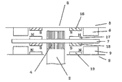
Fig. 2 is the sectional view of major part of the motor of the band brake among expression the present invention the 2nd embodiment.
Fig. 3 is the end view of the robot device that uses among expression prior art and the present invention.
Fig. 4 is the sectional view of the motor of expression band brake of the prior art.
Fig. 5 is the sectional view of major part of the motor of expression band brake of the prior art.
Symbol description
The A robot device
The B fixed arm
The C turning arm
The D upright arm
The E horizontal arm
The F wrist portion
The motor of 1 band brake
2 rotating shafts
3 brake portions
4 tooth bars
5 braking parts
6 the 1st pads
7 keep plates
8 armature
9 the 2nd pads
10 brake springs
11 calutrons
12 spring supports (braking parts side)
13 spring supports (calutron side)
14 support springs (braking parts side)
15 support springs (calutron side)
16 the 1st permanent magnets
17 the 2nd permanent magnets
18 the 3rd permanent magnets
19 the 4th permanent magnets
Specific embodiment
Below, embodiments of the invention are described with reference to the accompanying drawings.
Embodiment 1
Fig. 1 is the sectional view of major part of the motor of the band brake among expression the present invention the 1st embodiment.
The present invention constitutes the motor 1 that uses band brake in any case, when brake discharges, all can make keep plate 7 between the 1st pad 6 and the 2nd pad 9, and keep plate 7 does not contact with the 1st pad 6 and the 2nd pad 9.
The 1st embodiment represents to use the configuration example of support spring.
As shown in Figure 1, the braking parts 3 of the motor 1 of band brake is provided with a pair of spring support 12,13 that clips keep plate 7 in the end of rotating shaft 2.
The spring support 12 of braking parts 5 sides is configured to face than aforementioned the 1st pad 6 more near braking parts 5 sides, and the spring support 13 of calutron 11 sides is configured to face than aforementioned the 2nd pad 9 more near calutron 11 sides.Dispose a pair of support spring 14,15 between aforementioned keep plate 7 and each spring support 12,13.Aforementioned support spring 14,15 is pushed keep plate 7 respectively, and thus, keep plate 7 is positioned at the centre of two spring supports 12,13.
Thus, when brake discharges,, can make keep plate 7 all the time between the 1st pad 6 and the 2nd pad 9, can not contact the 1st pad 6 or the 2nd pad 9 by a pair of support spring 14,15.Because support spring 14,15 is compressed when braking, therefore can not become the obstacle of braking.
So be, can provide a kind of life-span long, maintenance cost is cheap, and the motor of the band brake of the safety that can brake effectively.
In addition, be the CD-ROM drive motor of turning arm, upright arm, horizontal arm and the wrist portion etc. of robot device by motor applications with this band brake, robot device is braked effectively, safety and maintenance cost are cheap.
In addition, also can make the spring pressure difference of two support springs 14,15 according to the use posture of the motor 1 of band brake.
For example, as shown in Figure 3, when the motor 1 of band brake was set to load side and is positioned at the below, can make load side was that the spring pressure of support spring 15 of calutron 11 sides is stronger than the spring pressure of the support spring 14 of braking parts 5 sides, to increase the supporting to gravity.
This 2nd embodiment represents to use the configuration example of permanent magnet.
As shown in Figure 2, the brake portion 3 of the motor 1 of band brake is on the relative position separately of aforementioned braking parts 5 and keep plate 7, opposite polarity the 1st permanent magnet 16 and the 2nd permanent magnet 17 on opposite face are installed, simultaneously on the relative position separately of aforementioned keep plate 7 and armature 8, opposite polarity the 3rd permanent magnet 18 and the 4th permanent magnet 19 on opposite face are installed.
The radial position of aforementioned the 1st permanent magnet 16 and the 2nd permanent magnet 17 is between aforementioned the 1st pad 6 and rotating shaft 2, and the radial position of the 3rd permanent magnet 18 and the 4th permanent magnet 19 is between aforementioned the 2nd pad 9 and rotating shaft 2.
Thus, when brake discharged, keep plate 7 was pulled to the braking parts side by the 1st permanent magnet 16 and the 2nd permanent magnet 17 that attracts each other, and was pulled to calutron 11 sides by the 3rd permanent magnet 18 and the 4th permanent magnet 19 that attracts each other simultaneously.Therefore, can make keep plate 7 all the time between the 1st pad 6 and the 2nd pad 9, can not contact the 1st pad 6 and the 2nd pad 9.
When under the situation of this 2nd embodiment, braking, because the attraction force acts of the 1st permanent magnet 16 and the 2nd permanent magnet 17 is for increasing the power that keep plate 7 is pushed to the 1st pad 6, in addition, the attraction force acts of the 3rd permanent magnet 18 and the 4th permanent magnet 19 is for increasing the power that the 2nd pad 9 is pushed to keep plate 7, and is therefore bigger than the braking force of the 1st embodiment.
So be, the same with the 1st embodiment, can provide a kind of life-span long, maintenance cost is cheap, and the motor of the band brake of the safety that can brake effectively.
In addition, be the CD-ROM drive motor of turning arm, upright arm, horizontal arm and the wrist portion etc. of robot device by motor applications with this band brake, robot device is braked effectively, safety and maintenance cost are cheap.
In addition, when the power of brake spring 10 is very big, also can make the 1st permanent magnet 16 and the 2nd permanent magnet 17, also have the 3rd permanent magnet 18 identical with the polarity of the opposite face of the 4th permanent magnet 19, when brake discharged, the repulsive force by magnet made keep plate 7 between the 1st pad 6 and the 2nd pad 9.
In addition, though the 1st embodiment and the 2nd embodiment do not have to install pad on keep plate, also pad can be installed on keep plate.
Claims (4)
1. the motor of a band brake, it is the distolateral brake portion that is provided with at rotating shaft,
And aforementioned brake portion comprise have the 1st pad and be arranged at the braking parts of fixed part, only be installed on sliding freely in the axial direction the keep plate of aforementioned rotating shaft, the armature by having the 2nd pad to the 1st pad of aforementioned braking parts push aforementioned keep plate brake spring, and attract the calutron of armature with brake off, it is characterized by:
The a pair of spring support of the aforementioned keep plate of clamping is set in the end of aforementioned rotating shaft, simultaneously the spring support of braking parts side is configured to face than aforementioned the 1st pad more near the braking parts side, and the spring support of calutron side is configured to face than aforementioned the 2nd pad more near the calutron side, and disposes support spring between keep plate and each spring support.
2. the motor of a band brake, it is the distolateral brake portion that is provided with at rotating shaft,
And aforementioned brake portion comprise have the 1st pad and be arranged at the braking parts of fixed part, only be installed on sliding freely in the axial direction the keep plate of aforementioned rotating shaft, the armature by having the 2nd pad to the 1st pad of aforementioned braking parts push aforementioned keep plate brake spring, and attract the calutron of armature with brake off, it is characterized by:
On the aforementioned braking parts separately position relative with keep plate, the the opposite polarity the 1st and the 2nd permanent magnet on opposite face is installed, simultaneously on the aforementioned keep plate separately position relative with armature, the the opposite polarity the 3rd and the 4th permanent magnet on opposite face is installed, the radial position of aforementioned the 1st, the 2nd permanent magnet is between aforementioned the 1st pad and rotating shaft, and the radial position of aforementioned the 3rd, the 4th permanent magnet is between aforementioned the 2nd pad and rotating shaft.
3. a robot device is characterized by: the motor with band brake as claimed in claim 1 or 2.
4. robot device as claimed in claim 3 is characterized by: with the motor of the aforementioned band brake drive motor as rotating basis.
Applications Claiming Priority (2)
| Application Number | Priority Date | Filing Date | Title |
|---|---|---|---|
| JP2006073201A JP4798543B2 (en) | 2006-03-16 | 2006-03-16 | Brake motor and robot apparatus equipped with the same |
| JP2006073201 | 2006-03-16 |
Publications (2)
| Publication Number | Publication Date |
|---|---|
| CN101051775A CN101051775A (en) | 2007-10-10 |
| CN100566081C true CN100566081C (en) | 2009-12-02 |
Family
ID=38595833
Family Applications (1)
| Application Number | Title | Priority Date | Filing Date |
|---|---|---|---|
| CNB2007100800346A Expired - Fee Related CN100566081C (en) | 2006-03-16 | 2007-03-05 | The motor of band brake and have the robot device of this motor |
Country Status (4)
| Country | Link |
|---|---|
| JP (1) | JP4798543B2 (en) |
| KR (1) | KR100869435B1 (en) |
| CN (1) | CN100566081C (en) |
| TW (1) | TW200803120A (en) |
Cited By (1)
| Publication number | Priority date | Publication date | Assignee | Title |
|---|---|---|---|---|
| CN103580550A (en) * | 2012-07-20 | 2014-02-12 | 株式会社安川电机 | Break apparatus, drive system and robot |
Families Citing this family (7)
| Publication number | Priority date | Publication date | Assignee | Title |
|---|---|---|---|---|
| JP5447451B2 (en) * | 2011-08-08 | 2014-03-19 | 株式会社安川電機 | robot |
| CN103644162A (en) * | 2013-11-18 | 2014-03-19 | 苏州蓝王机床工具科技有限公司 | Hydraulic motor with brake device |
| CN107053139A (en) * | 2017-04-11 | 2017-08-18 | 沈阳翰和科技工程有限公司 | A kind of automatic braking type truss manipulator |
| JP7251452B2 (en) * | 2019-11-15 | 2023-04-04 | 株式会社豊田自動織機 | brake system |
| CN110902387A (en) * | 2019-12-31 | 2020-03-24 | 北京华电光大环境股份有限公司 | Magnetic gripper and magnetic gripping device |
| JP2023019157A (en) | 2021-07-28 | 2023-02-09 | 山洋電気株式会社 | Electromagnetic brake device for motor |
| CN115446587B (en) * | 2022-08-25 | 2023-07-14 | 西南交通大学 | Railway wagon wheel pair bearing front cover dismounting system |
Citations (1)
| Publication number | Priority date | Publication date | Assignee | Title |
|---|---|---|---|---|
| US3665231A (en) * | 1969-03-21 | 1972-05-23 | Baumueller Gmbh A | Automatically adjustable single disc brake for motors |
Family Cites Families (7)
| Publication number | Priority date | Publication date | Assignee | Title |
|---|---|---|---|---|
| JPS5529745U (en) * | 1978-08-16 | 1980-02-26 | ||
| JPH02218588A (en) * | 1989-02-20 | 1990-08-31 | Tokico Ltd | Industrial robot |
| JPH02266132A (en) * | 1989-04-05 | 1990-10-30 | Fuji Electric Co Ltd | Noise suppressor for solenoid brake |
| JPH0735175A (en) * | 1993-07-23 | 1995-02-03 | Fuji Electric Co Ltd | Nonexciting electromagnetic braking device |
| JPH089589A (en) * | 1994-06-16 | 1996-01-12 | Yaskawa Electric Corp | Motor provided with brake |
| JP2006025580A (en) * | 2004-06-07 | 2006-01-26 | Kobelco Contstruction Machinery Ltd | Vertical motor drive with brake, and working machine |
| KR200375863Y1 (en) | 2004-11-24 | 2005-03-11 | 김종갑 | Motor brake device |
-
2006
- 2006-03-16 JP JP2006073201A patent/JP4798543B2/en not_active Expired - Fee Related
-
2007
- 2007-02-09 KR KR1020070013467A patent/KR100869435B1/en not_active IP Right Cessation
- 2007-03-05 CN CNB2007100800346A patent/CN100566081C/en not_active Expired - Fee Related
- 2007-03-07 TW TW096107886A patent/TW200803120A/en not_active IP Right Cessation
Patent Citations (1)
| Publication number | Priority date | Publication date | Assignee | Title |
|---|---|---|---|---|
| US3665231A (en) * | 1969-03-21 | 1972-05-23 | Baumueller Gmbh A | Automatically adjustable single disc brake for motors |
Cited By (1)
| Publication number | Priority date | Publication date | Assignee | Title |
|---|---|---|---|---|
| CN103580550A (en) * | 2012-07-20 | 2014-02-12 | 株式会社安川电机 | Break apparatus, drive system and robot |
Also Published As
| Publication number | Publication date |
|---|---|
| KR20070094462A (en) | 2007-09-20 |
| JP4798543B2 (en) | 2011-10-19 |
| KR100869435B1 (en) | 2008-11-21 |
| TW200803120A (en) | 2008-01-01 |
| JP2007252111A (en) | 2007-09-27 |
| TWI326151B (en) | 2010-06-11 |
| CN101051775A (en) | 2007-10-10 |
Similar Documents
| Publication | Publication Date | Title |
|---|---|---|
| CN100566081C (en) | The motor of band brake and have the robot device of this motor | |
| EP2504602B1 (en) | A magnetic braking device | |
| EP2400180A3 (en) | Magnetic spring system for use in a resonant motor | |
| CN101332966B (en) | Brake gear | |
| CN103161826A (en) | Power-off protection mechanism of magnetic suspension rotor support system | |
| CN102326010A (en) | Electromechanical arrangement for driving and/or braking shaft | |
| WO2012086060A1 (en) | Electromagnetic brake device for elevator | |
| JP4813302B2 (en) | Magnetic torque transmission device | |
| CN102777511A (en) | Electromagnetic clutch and air pump using same | |
| JP2006315818A (en) | Braking device for hoisting machine for elevator | |
| CN100392767C (en) | Magnetic suspension hard disc single free degree multi-function experiment platform | |
| JP2007146911A (en) | Vibration suppressing device | |
| JP5387006B2 (en) | Rotating machine | |
| CN111277111B (en) | Linear motor structure | |
| CN220416059U (en) | Power-off braking device and motor movement module | |
| JP2004224531A (en) | Disc brake device of elevator | |
| US20230392655A1 (en) | Brake apparatus, motor and robot | |
| CN208471433U (en) | A kind of brake | |
| CN114006499B (en) | Roller shutter motor comprising a reverse braking actuator | |
| KR102267756B1 (en) | Drop prevention apparatus using magnetic force in scribe head for dividing substrate | |
| CN102079092B (en) | Arm component of robot | |
| CN201651239U (en) | Belt pulley with a permanent magnetic buffering device | |
| KR20070104060A (en) | Disk brake device for vehicle | |
| JP4550602B2 (en) | Electromagnet device, drive device using electromagnet device, and elevator safety device using drive device | |
| ES2176092B1 (en) | OPERATING DEVICE FOR ROTATING PLATFORM. |
Legal Events
| Date | Code | Title | Description |
|---|---|---|---|
| C06 | Publication | ||
| PB01 | Publication | ||
| C10 | Entry into substantive examination | ||
| SE01 | Entry into force of request for substantive examination | ||
| C14 | Grant of patent or utility model | ||
| GR01 | Patent grant | ||
| CF01 | Termination of patent right due to non-payment of annual fee | ||
| CF01 | Termination of patent right due to non-payment of annual fee |
Granted publication date: 20091202 Termination date: 20170305 |