CN100564779C - The locking device of door handle - Google Patents
The locking device of door handle Download PDFInfo
- Publication number
- CN100564779C CN100564779C CNB2005100539376A CN200510053937A CN100564779C CN 100564779 C CN100564779 C CN 100564779C CN B2005100539376 A CNB2005100539376 A CN B2005100539376A CN 200510053937 A CN200510053937 A CN 200510053937A CN 100564779 C CN100564779 C CN 100564779C
- Authority
- CN
- China
- Prior art keywords
- handle
- door
- retainer
- block
- axial region
- Prior art date
- Legal status (The legal status is an assumption and is not a legal conclusion. Google has not performed a legal analysis and makes no representation as to the accuracy of the status listed.)
- Active
Links
- 230000000694 effects Effects 0.000 claims abstract description 6
- 238000009432 framing Methods 0.000 claims description 14
- 238000002788 crimping Methods 0.000 description 2
- 230000002687 intercalation Effects 0.000 description 2
- 238000009830 intercalation Methods 0.000 description 2
- 238000012856 packing Methods 0.000 description 2
- 230000002093 peripheral effect Effects 0.000 description 2
- 238000013475 authorization Methods 0.000 description 1
- 230000000903 blocking effect Effects 0.000 description 1
- 230000006835 compression Effects 0.000 description 1
- 238000007906 compression Methods 0.000 description 1
- 230000006378 damage Effects 0.000 description 1
- 230000009977 dual effect Effects 0.000 description 1
- 230000000704 physical effect Effects 0.000 description 1
Images


Classifications
-
- E—FIXED CONSTRUCTIONS
- E05—LOCKS; KEYS; WINDOW OR DOOR FITTINGS; SAFES
- E05C—BOLTS OR FASTENING DEVICES FOR WINGS, SPECIALLY FOR DOORS OR WINDOWS
- E05C3/00—Fastening devices with bolts moving pivotally or rotatively
- E05C3/02—Fastening devices with bolts moving pivotally or rotatively without latching action
- E05C3/04—Fastening devices with bolts moving pivotally or rotatively without latching action with operating handle or equivalent member rigid with the bolt
-
- E—FIXED CONSTRUCTIONS
- E05—LOCKS; KEYS; WINDOW OR DOOR FITTINGS; SAFES
- E05B—LOCKS; ACCESSORIES THEREFOR; HANDCUFFS
- E05B13/00—Devices preventing the key or the handle or both from being used
- E05B13/10—Devices preventing the key or the handle or both from being used formed by a lock arranged in the handle
-
- E—FIXED CONSTRUCTIONS
- E05—LOCKS; KEYS; WINDOW OR DOOR FITTINGS; SAFES
- E05C—BOLTS OR FASTENING DEVICES FOR WINGS, SPECIALLY FOR DOORS OR WINDOWS
- E05C3/00—Fastening devices with bolts moving pivotally or rotatively
- E05C3/02—Fastening devices with bolts moving pivotally or rotatively without latching action
- E05C3/04—Fastening devices with bolts moving pivotally or rotatively without latching action with operating handle or equivalent member rigid with the bolt
- E05C3/041—Fastening devices with bolts moving pivotally or rotatively without latching action with operating handle or equivalent member rigid with the bolt rotating about an axis perpendicular to the surface on which the fastener is mounted
Landscapes
- Engineering & Computer Science (AREA)
- Mechanical Engineering (AREA)
- Lock And Its Accessories (AREA)
- Patch Boards (AREA)
Abstract
The locking device of door handle of the present invention prevents to unblank and destroy lock by this activity of revolution that stops handle.Make described block be limited to the state of fixed frame for the position with described handle becomes securely, stop the revolution of handle, and keep this retainer blocked state with lock by retainer.
Description
Technical field
The present invention relates to such as uses such as switchboard containing box, rotate the locking device that predetermined angular makes the door handle that block ends, breaks away from from fixed frame side card by being located at handle on the door.
Background technology
For the fixed frame side opposite house of switchboard containing box outside the room etc. opens and closes, have a kind ofly L shaped handle that put down in writing in the following patent documentation, as shown in Figure 5 and Figure 6 to be installed at reveal.This L shaped handle is, with operation axial region 5 intercalation rotationally of handle 4 with the inside axis hole 3 of the affixed support body 2 of door 1 in, to end with supporting plate portion 7 cards of fixed frame 6 sides, the block 8 that breaks away from usefulness is linked to the front end of operation axial region 5, perhaps on this basis, be provided with operation axial region 5 fronts by the reception hole 9 of opening, engage with axis hole 3 inner face recesses 11 from the inwall open-work 10 of reception hole 9, the latch 12 that pins un-rotatably with respect to support body 2 of operation axial region 5 is contained in the leading section of described reception hole 9, tapered end unit 13 is contained in the leading section of reception hole 9, it is fixing to operate axial region 5, front end is provided with latch 12 is haunted from inwall open-work 10, the engagement member 15 of the cam part 14 that drives, be contained in the pars intermedia of reception hole 9 rotationally, the leading section of engagement member 15 can be linkedly linked with the rotor 16 of tapered end unit 13, more than these structures be familiar with by people.
As the locking device of above-mentioned door handle, when setting has the tapered end unit etc. of cylinder lock, to consider safety certainly, but it is said that the skill of nearest destruction tapered end is quite advanced, only relies on this cylinder lock, anti-theft measure is limited, so not very good.
No. the 242452nd, [patent documentation 1] Japanese Patent Laid
Problem of the present invention is, provide be suitable for above-mentioned anti-theft measure, promptly from appearance might as well, physical property might as well, people want attempting lock is made a mess of the locking device of also very difficult door handle.
Summary of the invention
In view of above-mentioned purpose, its main points are, door handle of the present invention, rotate predetermined angular by the handle that will be located at outer side of door, the lever operated axial region that runs through door is rotated, block and fixed frame that the door that its front portion had is inboard only block, break away from, it is characterized in that, be provided with rotation retainer freely, when the position of described handle is limited to described block under the state of fixed frame, stop the activity of described handle, on described retainer, be provided with described retainer and be held in state that stops described handle activity and the lock of keeping this state.
Adopt this structure,, just can stop the activity of retainer, so block can not deviate from from fixed frame as long as handle is not liberated from the location of lock.
Another main points of the present invention are, described rotation retainer freely, end plate and constituted by being fixed in installing plate on the door and the upright card of being located on this installing plate by being journaled into the framing component that this card only surrounds the leading section of described handle and keep on the plate, be located at described card and end in the lockhole on the plate by the lock of cylinder lock is inserted, then the framing component that the leading section of described handle is surrounded can not drop out.
Among the present invention, the card that will be provided with lockhole in advance ends plate and is fixed on the door, be supported on the only framing component on the plate of this card by rotating by the pin pivot, around the handle front portion, and above with the lockhole present position of described framing component by ending plate until described card, the lock with cylinder lock inserts in the described lockhole then, do not make firmly to drop out around the framing component that surrounds described handle, the block that causes when stoping described handle to rotate is from the disengaging of fixed frame.
Another main points of the present invention are, in order to make the revolution of operation axial region by described handle, adopted following structure to be, to turn round by make cylinder pail lock with key, latch is liberated from bearing cartridge portion, rotate described handle the operation axial region is turned round, described block is thrown off from fixed frame.
The present invention, the operation axial region of handle is rotated so that the block of the inboard of door is can block on the fixed frame the occasion of taking off at the body of switchboard containing box etc. except merely rotating predetermined angular, cylinder lock also is set on handle body by handle.
Adopt the present invention, whether no matter the tapered end of steering-type lock be installed on the handle, can both be formed on the retainer that the restriction handle rotates is set on the door, not only there is not traditional steering-type lock, if any, also can use pin etc. that the steering-type lock is unblanked such structure of simply door being opened, stop itself rotation of handle by utilizing retainer, and on retainer, lock, it visually with on the special rational faculty all can not be unblanked.
Again, in another invention, end on the board by the card that described framing component pivot is bearing in door, this framing component is rotated, the state that turns round the leading section with handle to surround, the lockhole that described card is ended plate is by a certain position, then, according to the shape that this framing component is dropped out from the state that surrounds described handle, end in the keyhole 19 of plate being locked in card on the cylinder lock, thus, the block that is arranged in the operation axial region leading section of handle can not deviate from from fixed frame.
The simple declaration of accompanying drawing
Fig. 1 is embodiments of the invention, after cylinder lock is locked with the front view of handle lock-out state.
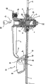
Fig. 2 is the longitudinal section of the handle portion of Fig. 1.
Fig. 3 unblanks, makes handle to be in the front view of free state above-mentioned cylinder lock.
Fig. 4 is the longitudinal section of the state of Fig. 3.
Fig. 5 is the front view of traditional door handle.
Fig. 6 is main the longitudinal section of Fig. 5.
The specific embodiment
For block is deviate from from the face side of door, can only with handle under rotating this prerequisite the retainer that stops this handle revolution usefulness be set, and in the outside of door, setting makes retainer keep the lock of handle blocked state.
(embodiment)
For above-mentioned conventional case (Fig. 5 and Fig. 6) is described in further detail, afterwards, describe with reference to Fig. 1~Fig. 4 in the above-mentioned numbering of mark (numbering 1~16).
As tapered end unit 13, used the cylinder lock that is assembled with known pin steering-type latch mechanism and disk steering-type latch mechanism, the fixed body portion of tapered end unit 13 forms one with operation axial region 5, the rotor 16 that only will be assembled with the disk steering gear inserts in the reception hole 9 of operation axial region 5, and anticreep is chimeric with the leading section of ring 16b and rotor 16.The cross section of rotor 16 oval-shaped interlock axial region 16a is embedded in the open slot 21 of columned engagement member 15 leading sections.The cam part 14 eccentric shapes of engagement member 15 are convexly set in front end face, and are inserted in being subjected in the groove 22 of latch 12 base end parts.
Outer peripheral face at described engagement member 15 is provided with endless groove 17, will embed in these endless grooves 17 with the O shape ring 18 of the reception hole 9 inner face crimping of operating axial region 5.
Under blocking, engage with supporting plate portion 7 by block 8, can not be open and door 1 is fixed into to fixed frame 6.The leading section of latch 12 is engaging with the inner face recess 11 of support body 2.Open door 1 o'clock inserts the key 20 of regulation in the keyhole 19 of rotor 16 of tapered end unit 13, after fixing releasing of lock with the rotor 16 of tapered end unit 13, with key 20 rotor 16 is turned round towards deciding direction.
Because engagement member 15 turns round linkedly with rotor 16, therefore, by cam part 14 traction-driven latches 12, its leading section is deviate from from the inner face recess 11 of support body 2, is introduced in the inwall open-work 10 of operation axial region 5.To operate fixing releasing of lock of 5 pairs of support body 2 of axial region thus, so handle 4 can turn round, by handle 4 is rotated towards deciding direction, block 8 breaks away from from the supporting plate portion 7 of fixed frame 6.Like this, by handle 4 is drawn towards the front direction, door 1 can be opened.
Leading section inner face at the axis hole 3 of support body 2 is provided with ring-type accommodating groove 32, will embed in the ring-type accommodating grooves 32 with the O shape ring 33 of the outer peripheral face crimping of operation axial region 5.Utilize this O shape ring 33, stop rainwater from the seam of support body 2 and handle 4, to be invaded.Support body 2, in the installing hole 34 of door 1, the revolution of the back side projection 37 of intermediate flange portion 36 being inserted door 1 stops in the hole 38, fixes with screw 38 ', uses the nut 39 that screws togather with bearing cartridge portion 35 to be fastened on the door 1 with 35 intercalations of bearing cartridge portion.Be inserted with circular pads 40 between intermediate flange portion 36 and door 1, this liner 40 can stop rainwater to stop intrusion the hole 38 from described installing hole 34 and revolution.
Below, use above-mentioned traditional L shaped handle that the portion that wants of the present invention is described.
On near the door 1 the lower front end portion of handle, will end the fixture 43 of the roughly T font that plate 42 formed by installing plate 41 with from the upright cards of establishing of installing plate 41, run through the through hole 44 and the door 1 of installing plate 41, fix with bolt 45.Again, end on the plate 42 at described card, be provided with cylinder lock 46 the lockhole 48 that chain shot 47 is locked, end on the plate 42 near the card above the installing plates 41 from this lockhole 48, be provided with framing component 50 by the scoop shape of pin 49 pivots supporting, form retainer 51 with described fixture 43.
This retainer 51 is to utilize notch 52 with the direction of arrow revolution up and down of framing component 50 courts, the lower front end portion 4 ' of described handle is surrounded, by being locked in the lockhole 48 on the chain shot 47 with cylinder lock 46, make it can not be towards return (Fig. 1 and Fig. 2) with the direction of arrow.
Under this state, handle can not be laterally movable, and block 8 is deviate from from fixed frame 6.
On the other hand, in case described lock 46 is unblanked, then framing component 50 relies on deadweight, utilize pin 49 to fall towards the direction opposite with above-mentioned arrow, the restriction cancellation (Fig. 3, Fig. 4) of the lower front end portion 4 ' of handle can be turned round towards the direction of arrow shown in Figure 1 by making handle 4 thus, block 8 rotates with same, to end state with the card of fixed frame 6 and throw off, the front direction from the accompanying drawing of the door 1 by the supporting of hinge (not shown) pivot can be opened thus.
Certainly,, block 8 cards can be ended on fixed frame 6, door 1 is shut and lock (Fig. 1, Fig. 2) by being reversed aforesaid operations.
In addition, under the state that described framing component 50 breaks away from from the encirclement of the lower front end portion 4 ' of handle, block 26 revolutions that make handle 4 by axial region 27, use key 20 that the latch 12 of cylinder lock is thrown off then, described handle 4 is rotated, that is, can turn round in order to make handle 4, certainly must be through the dual releasing operation of retainer and cylinder pail lock.
Except the room outside the switchboard containing box, in the field of the door of the sort of framework that the outsider can not enter without authorization etc., also can use the present invention.
Claims (3)
1. the locking device of a door handle by being located at the handle rotation predetermined angular of outer side of door, rotates the operation axial region of the handle that runs through door, and block and fixed frame that the door that its front portion had is inboard only block, break away from, it is characterized in that,
Be provided with rotation retainer freely, this retainer surrounds and keeps by the leading section with described handle, position at described handle is limited to described block under the state of fixed frame, stop the activity of described handle, and, on described retainer, be provided with described retainer is remained in state that stops described handle activity and the lock of keeping this hold mode.
2. the locking device of door handle as claimed in claim 1, it is characterized in that, described rotation retainer freely, end plate and constituted by being fixed in installing plate on the door and the upright card of being located on this installing plate by being journaled into the framing component that this card only surrounds the leading section of described handle and kept on the plate, be located at described card and end in the lockhole on the plate by the chain shot of cylinder lock is inserted, the framing component that the leading section of described handle is surrounded can not drop out.
3. the locking device of door handle as claimed in claim 1, it is characterized in that, in order to make the revolution of operation axial region by described handle, by make the cylinder lock revolution with key, latch is liberated from bearing cartridge portion, rotate described handle the operation axial region is turned round, described block is thrown off from fixed frame.
Applications Claiming Priority (2)
| Application Number | Priority Date | Filing Date | Title |
|---|---|---|---|
| JP2004193925 | 2004-06-30 | ||
| JP2004193925A JP4520232B2 (en) | 2004-06-30 | 2004-06-30 | Locking device for door handle |
Publications (2)
| Publication Number | Publication Date |
|---|---|
| CN1715600A CN1715600A (en) | 2006-01-04 |
| CN100564779C true CN100564779C (en) | 2009-12-02 |
Family
ID=35791325
Family Applications (1)
| Application Number | Title | Priority Date | Filing Date |
|---|---|---|---|
| CNB2005100539376A Active CN100564779C (en) | 2004-06-30 | 2005-03-08 | The locking device of door handle |
Country Status (4)
| Country | Link |
|---|---|
| JP (1) | JP4520232B2 (en) |
| KR (1) | KR100750580B1 (en) |
| CN (1) | CN100564779C (en) |
| TW (1) | TWI262234B (en) |
Families Citing this family (6)
| Publication number | Priority date | Publication date | Assignee | Title |
|---|---|---|---|---|
| WO2009100030A2 (en) * | 2008-01-31 | 2009-08-13 | Hartwell Corporation | Tool operated channel latch |
| SE0702814L (en) * | 2007-12-18 | 2008-10-21 | Assa Oem Ab | Handle arrangement |
| JP5294886B2 (en) * | 2009-01-07 | 2013-09-18 | Ykk Ap株式会社 | Handle device and joinery |
| KR101090775B1 (en) * | 2011-06-03 | 2011-12-08 | 고영균 | Lever typed handle and lock assembly for lever typed handle |
| CN210483266U (en) * | 2019-07-23 | 2020-05-08 | 易思亮 | Door stop for blocking door handle from rotating |
| KR102147343B1 (en) * | 2020-05-27 | 2020-08-24 | 주식회사 윈텍 | Fingerprint reader lock for chest of drawers |
Family Cites Families (10)
| Publication number | Priority date | Publication date | Assignee | Title |
|---|---|---|---|---|
| JPS6319662U (en) * | 1986-07-22 | 1988-02-09 | ||
| JPH075999Y2 (en) * | 1989-11-10 | 1995-02-15 | 彰 市原 | Opening device for inner tube lining tube |
| US5123683A (en) * | 1990-12-21 | 1992-06-23 | Emhart Inc. | Handleset with adjustable latch retracting mechanism |
| JPH0823239B2 (en) * | 1993-03-04 | 1996-03-06 | タキゲン製造株式会社 | Door lock handle device |
| JP3169481B2 (en) * | 1993-05-28 | 2001-05-28 | 大阪金具株式会社 | Unlock prevention device by key |
| JP2605403Y2 (en) * | 1993-09-29 | 2000-07-17 | 株式会社西製作所 | Handle lock |
| JP2724452B2 (en) * | 1995-10-27 | 1998-03-09 | タキゲン製造株式会社 | Lock handle device for waterproof door |
| JP2979307B1 (en) * | 1998-05-14 | 1999-11-15 | タキゲン製造株式会社 | Tightening handle device |
| JP3546802B2 (en) * | 2000-03-31 | 2004-07-28 | タキゲン製造株式会社 | Lock handle device |
| JP4080175B2 (en) * | 2001-05-07 | 2008-04-23 | 美和ロック株式会社 | Handle lock cover |
-
2004
- 2004-06-30 JP JP2004193925A patent/JP4520232B2/en not_active Expired - Lifetime
-
2005
- 2005-02-16 TW TW094104410A patent/TWI262234B/en active
- 2005-03-08 CN CNB2005100539376A patent/CN100564779C/en active Active
- 2005-03-09 KR KR1020050019510A patent/KR100750580B1/en active IP Right Grant
Also Published As
| Publication number | Publication date |
|---|---|
| CN1715600A (en) | 2006-01-04 |
| JP2006016797A (en) | 2006-01-19 |
| KR100750580B1 (en) | 2007-08-20 |
| KR20060043574A (en) | 2006-05-15 |
| TWI262234B (en) | 2006-09-21 |
| TW200600655A (en) | 2006-01-01 |
| JP4520232B2 (en) | 2010-08-04 |
Similar Documents
| Publication | Publication Date | Title |
|---|---|---|
| CN100564779C (en) | The locking device of door handle | |
| US8234891B2 (en) | Combination cam lock with improved combination change mode | |
| US8104314B2 (en) | Device for actuating the lock in the door or flap of a vehicle | |
| TWI510701B (en) | Lock mechanism | |
| US8267442B2 (en) | Outer operational device for panic exit door lock | |
| US4030321A (en) | Padlock with protected slide bolt and locking means | |
| KR20080095832A (en) | Security system for entrance barriers | |
| CN100354496C (en) | Door locking device | |
| US20170044796A1 (en) | Symmetrical uni-directional single action centered cylinder keyless deadbolt door lock assembly for right or left hand hung doors | |
| CN101228330A (en) | Cylinder lock with modified cam | |
| CN1197879A (en) | Lockset | |
| KR970065947A (en) | Z-bar security system with key and locking latch | |
| LT4719B (en) | A cylinder lock | |
| US20050231363A1 (en) | Self-adjusting cam assembly | |
| KR0135384B1 (en) | Lock handle device for a door | |
| WO2006033566A3 (en) | Basic mechanical automatic door's lock with central gearbox | |
| US7805967B1 (en) | Universal deadbolt lock knob immobilizer | |
| ITBO950565A1 (en) | SAFETY DEVICE FOR DOUBLE MAP LOCKS. | |
| JP4200241B2 (en) | Cam feed prevention mechanism | |
| KR100501491B1 (en) | Device of free revolution door lock for robbery prevention | |
| JP4200240B2 (en) | Cylinder lock with indicator | |
| JP2004156279A (en) | Locking device for door | |
| EP4339402A1 (en) | A dual-cylinder lock assembly | |
| JP3992675B2 (en) | Lock and thumb turn | |
| CA2808699C (en) | Self-adjusting cam assembly |
Legal Events
| Date | Code | Title | Description |
|---|---|---|---|
| C06 | Publication | ||
| PB01 | Publication | ||
| C10 | Entry into substantive examination | ||
| SE01 | Entry into force of request for substantive examination | ||
| C14 | Grant of patent or utility model | ||
| GR01 | Patent grant |