CN100558306C - System based on flushing flow control Surgery Systems - Google Patents
System based on flushing flow control Surgery Systems Download PDFInfo
- Publication number
- CN100558306C CN100558306C CNB2005800092905A CN200580009290A CN100558306C CN 100558306 C CN100558306 C CN 100558306C CN B2005800092905 A CNB2005800092905 A CN B2005800092905A CN 200580009290 A CN200580009290 A CN 200580009290A CN 100558306 C CN100558306 C CN 100558306C
- Authority
- CN
- China
- Prior art keywords
- obstruction
- rate
- flushing pressure
- stage
- aspiration vacuum
- Prior art date
- Legal status (The legal status is an assumption and is not a legal conclusion. Google has not performed a legal analysis and makes no representation as to the accuracy of the status listed.)
- Active
Links
Images


Classifications
-
- A—HUMAN NECESSITIES
- A61—MEDICAL OR VETERINARY SCIENCE; HYGIENE
- A61F—FILTERS IMPLANTABLE INTO BLOOD VESSELS; PROSTHESES; DEVICES PROVIDING PATENCY TO, OR PREVENTING COLLAPSING OF, TUBULAR STRUCTURES OF THE BODY, e.g. STENTS; ORTHOPAEDIC, NURSING OR CONTRACEPTIVE DEVICES; FOMENTATION; TREATMENT OR PROTECTION OF EYES OR EARS; BANDAGES, DRESSINGS OR ABSORBENT PADS; FIRST-AID KITS
- A61F9/00—Methods or devices for treatment of the eyes; Devices for putting-in contact lenses; Devices to correct squinting; Apparatus to guide the blind; Protective devices for the eyes, carried on the body or in the hand
- A61F9/007—Methods or devices for eye surgery
- A61F9/00736—Instruments for removal of intra-ocular material or intra-ocular injection, e.g. cataract instruments
- A61F9/00745—Instruments for removal of intra-ocular material or intra-ocular injection, e.g. cataract instruments using mechanical vibrations, e.g. ultrasonic
-
- A—HUMAN NECESSITIES
- A61—MEDICAL OR VETERINARY SCIENCE; HYGIENE
- A61M—DEVICES FOR INTRODUCING MEDIA INTO, OR ONTO, THE BODY; DEVICES FOR TRANSDUCING BODY MEDIA OR FOR TAKING MEDIA FROM THE BODY; DEVICES FOR PRODUCING OR ENDING SLEEP OR STUPOR
- A61M3/00—Medical syringes, e.g. enemata; Irrigators
- A61M3/02—Enemata; Irrigators
- A61M3/0204—Physical characteristics of the irrigation fluid, e.g. conductivity or turbidity
- A61M3/0216—Pressure
-
- A—HUMAN NECESSITIES
- A61—MEDICAL OR VETERINARY SCIENCE; HYGIENE
- A61M—DEVICES FOR INTRODUCING MEDIA INTO, OR ONTO, THE BODY; DEVICES FOR TRANSDUCING BODY MEDIA OR FOR TAKING MEDIA FROM THE BODY; DEVICES FOR PRODUCING OR ENDING SLEEP OR STUPOR
- A61M3/00—Medical syringes, e.g. enemata; Irrigators
- A61M3/02—Enemata; Irrigators
- A61M3/0204—Physical characteristics of the irrigation fluid, e.g. conductivity or turbidity
- A61M3/022—Volume; Flow rate
-
- A—HUMAN NECESSITIES
- A61—MEDICAL OR VETERINARY SCIENCE; HYGIENE
- A61M—DEVICES FOR INTRODUCING MEDIA INTO, OR ONTO, THE BODY; DEVICES FOR TRANSDUCING BODY MEDIA OR FOR TAKING MEDIA FROM THE BODY; DEVICES FOR PRODUCING OR ENDING SLEEP OR STUPOR
- A61M3/00—Medical syringes, e.g. enemata; Irrigators
- A61M3/02—Enemata; Irrigators
- A61M3/0233—Enemata; Irrigators characterised by liquid supply means, e.g. from pressurised reservoirs
- A61M3/0254—Enemata; Irrigators characterised by liquid supply means, e.g. from pressurised reservoirs the liquid being pumped
- A61M3/0258—Enemata; Irrigators characterised by liquid supply means, e.g. from pressurised reservoirs the liquid being pumped by means of electric pumps
-
- A—HUMAN NECESSITIES
- A61—MEDICAL OR VETERINARY SCIENCE; HYGIENE
- A61B—DIAGNOSIS; SURGERY; IDENTIFICATION
- A61B17/00—Surgical instruments, devices or methods, e.g. tourniquets
- A61B2017/00973—Surgical instruments, devices or methods, e.g. tourniquets pedal-operated
-
- A—HUMAN NECESSITIES
- A61—MEDICAL OR VETERINARY SCIENCE; HYGIENE
- A61M—DEVICES FOR INTRODUCING MEDIA INTO, OR ONTO, THE BODY; DEVICES FOR TRANSDUCING BODY MEDIA OR FOR TAKING MEDIA FROM THE BODY; DEVICES FOR PRODUCING OR ENDING SLEEP OR STUPOR
- A61M1/00—Suction or pumping devices for medical purposes; Devices for carrying-off, for treatment of, or for carrying-over, body-liquids; Drainage systems
- A61M1/71—Suction drainage systems
- A61M1/77—Suction-irrigation systems
-
- A—HUMAN NECESSITIES
- A61—MEDICAL OR VETERINARY SCIENCE; HYGIENE
- A61M—DEVICES FOR INTRODUCING MEDIA INTO, OR ONTO, THE BODY; DEVICES FOR TRANSDUCING BODY MEDIA OR FOR TAKING MEDIA FROM THE BODY; DEVICES FOR PRODUCING OR ENDING SLEEP OR STUPOR
- A61M2205/00—General characteristics of the apparatus
- A61M2205/33—Controlling, regulating or measuring
- A61M2205/3368—Temperature
-
- A—HUMAN NECESSITIES
- A61—MEDICAL OR VETERINARY SCIENCE; HYGIENE
- A61M—DEVICES FOR INTRODUCING MEDIA INTO, OR ONTO, THE BODY; DEVICES FOR TRANSDUCING BODY MEDIA OR FOR TAKING MEDIA FROM THE BODY; DEVICES FOR PRODUCING OR ENDING SLEEP OR STUPOR
- A61M2205/00—General characteristics of the apparatus
- A61M2205/50—General characteristics of the apparatus with microprocessors or computers
-
- A—HUMAN NECESSITIES
- A61—MEDICAL OR VETERINARY SCIENCE; HYGIENE
- A61M—DEVICES FOR INTRODUCING MEDIA INTO, OR ONTO, THE BODY; DEVICES FOR TRANSDUCING BODY MEDIA OR FOR TAKING MEDIA FROM THE BODY; DEVICES FOR PRODUCING OR ENDING SLEEP OR STUPOR
- A61M3/00—Medical syringes, e.g. enemata; Irrigators
- A61M3/02—Enemata; Irrigators
- A61M3/0202—Enemata; Irrigators with electronic control means or interfaces
Landscapes
- Health & Medical Sciences (AREA)
- Public Health (AREA)
- Engineering & Computer Science (AREA)
- Veterinary Medicine (AREA)
- Biomedical Technology (AREA)
- Heart & Thoracic Surgery (AREA)
- Life Sciences & Earth Sciences (AREA)
- Animal Behavior & Ethology (AREA)
- General Health & Medical Sciences (AREA)
- Hematology (AREA)
- Anesthesiology (AREA)
- Ophthalmology & Optometry (AREA)
- Nuclear Medicine, Radiotherapy & Molecular Imaging (AREA)
- Surgery (AREA)
- Vascular Medicine (AREA)
- Physics & Mathematics (AREA)
- Fluid Mechanics (AREA)
- Surgical Instruments (AREA)
- External Artificial Organs (AREA)
- Dental Tools And Instruments Or Auxiliary Dental Instruments (AREA)
Abstract
Can detect obstruction beginning or other surgery incidents and obstruction and remove Surgery Systems constantly.For helping to avoid drift overheated, system uses the flushing flow rate to determine the temperature of eyes, and if predict overheated situation, automatically reduce the electric power of head.Instead or in addition, the electric power that system monitoring is expended by head, the broaching load on its expression drift, and automatically adjust the electric power of drift or stroke so that the load that increases on the compensation drift.
Description
The cross reference of related application
The application is the common unsettled u.s. patent application serial number of submitting on April 5th, 2,004 10/818,314 part continuation application, require its priority 120 times at 35U.S.C. §, this common unsettled U.S. Patent application is 35U.S.C. § 119 times, require the priority of the U.S. Provisional Application sequence number 60/552,240 of submission on March 22nd, 2004.The application requires priority that submit to, U.S. provisional application sequence number 60/587,693 on July 14th, 2004 also 35U.S.C. § 119 times.
Technical field
The application relates generally to area of ophthalmic surgery, and more particularly, relates to based on the definite result who comprises flushing pressure, the method for the surgical parameters of control phacoemulsification systems.
Background technology
Human eye is used for by being called the limpid outer part transillumination of cornea, and by crystalline lens, on retina, provides vision with image focusing.The quality of focusedimage comprises the size and the shape of eyes by many factors, and cornea and lenticular transparency and decide.When age or disease cause crystalline lens to become not too transparent,, cause vision to reduce because transmissive reduces to amphiblestroid light.This defective medically is called cataract.Be used for cataractous acceptable treatment and be Surgical removal of cataracts and crystalline lens is replaced with prosthetic lens (IOL).In the U.S., use the surgical technic that is called Phacoemulsification, remove most of cataractous lenses.During this process, insert in the ill crystalline lens thin cutting punch and ultrasonic vibration.Liquefaction of vibration cutting punch or emulsifying crystalline lens are so that make crystalline lens sucking-off eyes.In a single day ill crystalline lens shifts out, and is substituted by IOL.
The typical ultrasonic surgical equipment that is suitable for ophthalmic procedures comprises the head that ultrasound wave drives, additional cutting punch, irrigating canula and automatically controlled.Nose assembly is connected to control station by cable or adapter and flexible pipe.The surgeon is transported to the cutting punch of head and is applied to structural ultrasonic electric weight in any fixed time control by pushing the pedal request reaches the maximum of the electric power of setting on control station electric power.Flexible pipe is carried flush fluid and is drawn the suction fluid from eyes by nose assembly.
The operating portion of head is resonance rod or the action bars centrally-located, empty that is connected to the piezoquartz group.Crystal is subjected to operating board control and during phacoemulsification, the supersonic vibration of feed drive action bars and appended cutting punch.By flexible attachment, in the empty body of head or shell, hang crystal/operation rod.Handpiece body terminates in the diameter reduction portion or conehead of far-end of body.Conehead is screwed on so that hold irrigating canula in the outside.Similarly, internally screw on the action bars thorax so that hold the external screw-thread of cutting punch at its far-end.Irrigating canula also has the female thread thorax on the external screw thread that is screwed in conehead.Adjust cutting punch so that drift only protrudes the opening scheduled volume of irrigating canula.
In use, the end of cutting punch and irrigating canula is inserted in the little otch of the preset width in cornea, sclera or other positions.By the ultrasound procedure bar of crystal-driven, in irrigating canula, along a kind of known cutting punch of its longitudinal axis supersonic vibration, thus the selected tissue of emulsifying on the spot.The empty thorax of cutting punch is communicated with the thorax in the action bars, and the thorax in the action bars is communicated with suction channel from the head to the operating board again.Other suitable cutting punch comprise the piezoelectric element that produces vertical and torsional oscillation.An example of this cutting punch was described among 769 (Boukhny) at U.S. Patent number 6,402, and its content is incorporated herein for your guidance.
The pressure of the reduction in the operating board or vacuum source draw emulsified tissue or be drawn into the collecting device from eyes by opening, cutting punch and the action bars thorax and the suction channel of cutting punch.By the inner surface of irrigating canula and the circlet shape crack between cutting punch, inject saline solution or other irrigations of surgery location, help the suction emulsified tissue.
A kind of known surgical technic is can make otch enter the anterior chamber of eyes to the greatest extent less to bring out scattered-light risk so that reduce.These little otch cause irrigating canula and vibrate the wound of tightening very much that drift pushes tightly.Friction between irrigating canula and vibration drift produces heat.By flowing into the fluidic cooling effect of suction in the drift, reduce the risk of the overheated and tissue of burn of drift.
, make the drift heating, thereby reduce cooling and cause temperature increase, the tissue of this incision of may burning because emulsified tissue becomes and blocks or when stopping up, can reduce or eliminate suction streams when drift.In addition, in blocking period, bigger vacuum can form in suction tube so that when otch finally breaks, can aspirate more multithread body apace from eyes, may cause other damages of atrophy of eyeball or eyes.
Known device has used the big increase that detects aspiration vacuum, and based on specific predetermined vacuum level, detects the pick off that stops up.Detect obstruction based on this, can reduce the electric power of head and/or can increase flushing or suction streams.See U.S. patent sequence number 5,591,127,5,700,240 and 5,766,146 (Barwick, people such as Jr.), its full content is incorporated herein for your guidance.Yet these equipment use fixed aspiration vacuum level to come the triggering system response.This fix level is based on the threshold value of the fixed percentage of selected upper vacuum limit.Yet,, limit the use and the efficient of these systems because they just respond when reaching predetermined vacuum level.People's such as Boukhny United States Patent (USP) 6,179,808 has been described when temperature exceeds the preset limit that calculates based on the flushing flow of measuring or estimate, reduces the system of signal amplitude and/or dutycycle, and its full content is incorporated herein for your guidance.
Because in fact, during the difference obstruction stage, vacuum level can change in the short time cycle, can improve known clogging detecting system thus.Should be scheduled to the too low system that causes of vacuum limit setting and change its operating parameter too early, and after eliminating obstruction, keep those parameters.Cause system's value of being set to change over the too approaching actual occurrence that stops up the too high meeting of limit setting, and before removing obstruction, the value of being set change back rated value.In addition, when stopping up cutting punch, the maximization cutting efficiency, the maximization cutting efficiency that therefore when detect blockage, increases electric power, but increase make drift on every side organize superheated risk.
In addition, in whole surgery, drift is pressed to crystalline lens so that the emulsifying lens tissue sometimes, and drift does not contact with crystalline lens sometimes.Yet ultrasonic energy still exists till the surgeon releases the pedal, even when the suction substance of lens, the surgeon makes drift be pulled away from crystalline lens, or crystalline lens also is like this when moving apart drift.Operation efficient reduces, and the energy of waste can cause the unnecessary heating of drift, and this may increase the probability of the tissue of the incision of burning undesirably.
Therefore, still need to exist a kind of clogging detecting system, can detect the appearance and the removing of stopping up in the surgical aspiration system more accurately.Can use this information correspondingly to adjust electric power by control system, for example during stopping up, increase electric power so that improve the cutting efficiency of ultrasonic drift and/or when relative temperature reaches predetermined threshold, reduce electric power so that prevent excessive heat.Detect the load detection system when drift no longer contacts with substance of lens and automatically adjust electric power by increasing, can further increase cutting efficiency.
Summary of the invention
According to an embodiment, a kind of by setting up threshold temperature and the flushing pressure that monitors in the flushing pipe that extends to ultrasonic handpiece, the method for control Surgery Systems.Calculate the flow rate of flush fluid and be used for the caloric receptivity that flush fluid flows.By for the temperature of determining eyes relatively or analyze caloric receptivity and offer the electric power of ultrasonic handpiece, determine the temperature of eyes, with itself and threshold temperature comparison.Based on the comparison, adjust the electric weight of the cutting punch that is transported to ultrasonic handpiece as required.
According to another embodiment, the flushing pressure of setting up threshold temperature and monitoring ultrasonic handpiece.The caloric receptivity that calculates the flush fluid flow rate and be identified for the flush fluid flow rate.Based on caloric receptivity with offer the electric power of ultrasonic handpiece, determine the temperature of eyes.Eye temperature and threshold temperature are compared.In addition, determine the rate of change of flushing pressure, and, determine to stop up level based on rate of change.Based on stopping up level and comparing, adjust the electric power of the cutting punch that is transported to ultrasonic handpiece as required.
In another embodiment, the method for control Surgery Systems comprises and sets up threshold temperature, monitors flushing pressure and calculate the flow rate of flush fluid that the caloric receptivity of the flush fluid flow rate of calculating based on being used for and offer the electric power of ultrasonic handpiece is determined the temperature of eyes.Eye temperature and threshold temperature are compared.In addition, determine the rate of change of flushing pressure.Based on rate of change, definite level of stopping up, and, adjust the electric power of the cutting punch that is transported to ultrasonic handpiece as required based on stopping up level and comparing.For example,, can reduce the electric power that is transported to head, and if determine that temperature is lower than threshold temperature, can keep or increase electric power if determined temperature exceeds threshold temperature.
According to each embodiment,, can adjust electric power by stroke or the amplitude that the head of adjusting dutycycle or adjustment ultrasonic handpiece is exported.Obstruction level that can identification comprise obstruction beginning or preliminary indication, stop up the situation in early stage, stop up fully, stop up and remove or recover from stopping up to remove.
Description of drawings
With reference now to accompanying drawing,, wherein, identical reference marker is represented corresponding parts, wherein:
Fig. 1 is the axonometric chart of the exemplary surgical system that can be used by each embodiment;
Fig. 2 is the block diagram of the parts of expression Surgery Systems;
The exemplary ultrasonic handpiece that the explanation of Fig. 3 A-B example is used by each embodiment;
Fig. 4 is the example explanation rate of change based on model and one or more operating parameters, adjusts the flow chart of an embodiment of the method for the electric power that is transported to head;
The explanation of Fig. 5 example can be by the obstruction level of embodiments of the invention use;
The explanation of Fig. 6 example is stopped up level, aspiration vacuum and flushing pressure figure in difference shown in Figure 5;
Fig. 7 is that the example explanation is used to adjust electric power so that prevent the flow chart of an embodiment of the superheated method of pick off drift;
Fig. 8 is a kind of more detail flowchart of realizing of embodiment shown in Figure 7;
The explanation of Fig. 9 a-9b example has the example burst mode pulses of uniform amplitude and different turn-off times, by the different turn-off times of following pressure-controlled of pedal;
The explanation of Figure 10 example has the exemplary pulse mode pulse of different duty, and dutycycle is controlled by pedal depression;
The explanation of Figure 11 example detects power stage according to the interpulse non-zero of the cutting of an embodiment;
Figure 12 is that example illustrates based on electric power, threshold value and Calculation of Sensitivity, the flow chart of the method for adjustment electric power;
Figure 13 is the sketch map of the head power-supply system that can be used by embodiment;
The explanation of Figure 14 example is according to another embodiment, and the non-zero with the persistent period that is shorter than the detection power stage persistent period shown in Figure 11 detects power stage;
The explanation of Figure 15 example is according to another embodiment, and the non-zero with the persistent period that changes in time of cutting inter-stage detects power stage;
Figure 16 example explanation cut interpulse independent non-zero and is detected power pulse according to another embodiment, and in cutting with to detect between power pulse be zero electric power;
Figure 17 is according to another embodiment, and interpulse independent detection power pulse is cut in the example explanation, and than the persistent period in shorter detection power pulse of the persistent period of the detection power pulse shown in Figure 16;
Figure 18 is according to another embodiment, and the independent non-zero that the example explanation has the persistent period that changes in time detects power pulse;
Figure 19 is according to another embodiment, and the example explanation just in time non-zero before the cutting pulse detects power pulse;
Figure 20 is according to another embodiment, and the example explanation just in time detects power pulse at the postimpulse non-zero of cutting;
Figure 21 is according to another embodiment, and example illustrates independent detection power pulse that cutting is interpulse and the detection power measurement that is carried out based on the detection power pulse of decay;
The explanation of Figure 22 example detects the measurement that power pulse is carried out with respect to decaying more slowly;
The explanation of Figure 23 example detects the measurement that power pulse is carried out with respect to faster decay; And
Figure 24 is according to another embodiment, and the example explanation is measured with respect to the detection that the attenuation rate of cutting pulse is carried out after the cutting pulse is converted to low level from high level.
The specific embodiment
This description is described to be used for controlling and is used in for example embodiment of the method for the Surgery Systems of phacoemulsification operation.Embodiment provides the variation of pressure stage that can be by detecting suction system, rinse-system or its combination, detects the surgery incident stage of (such as stopping up), and for example stopping up beginning, stopping up the situation in early stage, stopping up fully, and the Surgery Systems that when stops up releasing.By monitoring that how suction or irrigation pressure level change, and can accurately detect the beginning and the end of obstruction.As long as detect obstruction, the Surgery Systems of programming to increase the electric power that can be used for head by the stroke that increases drift or by increasing the dutycycle of impulse ultrasound electric power.
For helping to avoid drift overheated, wash flow rate and predict overheated situation if Surgery Systems monitors, automatically be reduced to the electric power of head.Instead, perhaps in addition, can monitor the electric weight that draws by head, the cutting load on its expression drift.Can use this information automatically to adjust the electric power of drift or stroke (displacement) so that the load variations on the compensation drift.In following description, with reference to the accompanying drawings, accompanying drawing passes through example, but is not restriction, the specific embodiment that expression can utilize.
By suitable hardware or software control, can on commercially available Surgery Systems or control station, realize embodiment.In Fig. 1 generally suitable system 100 of example explanation with and expression can be from Alcon Laboratories, Inc., 6201South Freeway, Q-148, Fort Worth, Texas 76134 obtains
 Visual system.
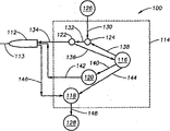
Fig. 2 is exemplary control system 100 of example explanation in further detail.Control system 100 is used for operating ultrasonic handpiece 112 and comprises control station 114, and this control station comprises control module or CPU116, suction, vacuum or peristaltic pump 118, head power supply 120, irrigation pressure sensor 122 and valve 124.Control station 114 can be commercially available surgery control station, such as
Surgery Systems also can be from Alcon Laboratories, and Inc. obtains.
Can utilize various ultrasonic handpieces 112 and cutting punch, include but not limited in United States Patent (USP) sequence number 3,589,363; 4,223,676; 4,246,902; 4,493,694; 4,515,583; 4,589,415; 4,609,368; 4,869,715; 4,922,902; 4,989,583; 5,154,694 and 5,359, head described in 996 and drift, its full content is incorporated herein for your guidance.For the purpose of illustration, exemplary head has been shown in Fig. 3 A-B, but has not been restriction.
With reference to figure 2, CPU116 can be any suitable microprocessor, microcontroller, computer or digital logic controller again.Pump 118 can be wriggling, dividing plate, venturi tube or other suitable pumps.Power supply 120 can be any suitable ultrasonic drivers, such as being integrated in
 In the Surgery Systems, also can be from Alcon Laboratories, Inc. obtains.Valve 124 can be any suitable valve, such as the activated pinch valve of solenoid.Can provide flush fluid, such as the injection of salt by the Yanyuan 126 of any commercially available rinse solution that provides is provided in bottle or bag.
In the use, irrigation pressure sensor 122 is connected to head 112 and injects fluid source 126 by clean-up line 130,132 and 134.Irrigation pressure sensor 122 is measured from the source 126 pressure to the flush fluid of head 112, and by cable 136, this information is sent to CPU116.Can use the irrigation fluid pressure data by CPU116, use software command, control the operating parameter of this control station 114.For example, CPU116 can pass through cable 140, changes the output that sends to the power supply 120 of head 112 and drift 113 by power cable 142.CPU116 also can use the data that provided by irrigation pressure sensor 122 to come by cable 144, changes the operation of pump 118.Pump 118 from head 112 suction fluids, and by pipeline 148, injects collection container 128 by pipeline 146.CPU116 also can use the application output of the data that provided by irrigation pressure sensor 122 and power supply 120 so that audible sound is offered the user.Can find the other details of relevant these Surgery Systemss in United States Patent (USP) sequence number 6,179,808 people such as () Boukhny and 6,261,283 people such as () Morgan, its full content is incorporated herein for your guidance.
In one embodiment, control station 114 can be based on the stage of occlusion event, and control is transported to the electric weight of head 112.More particularly, based on aspiration vacuum level, irrigation pressure level, or the variation of aspiration vacuum and irrigation pressure level, carry out the electric power adjustment.Variation can be for example aspiration vacuum and/or the increase of flushing pressure or the rate of change of minimizing.
As shown in Figure 4, can be transported to the adjustment of the electric weight of head.Initially, in step 400, on the cycle, detect during obstruction or other surgery incidents the surgical procedures Parameter Map at certain hour.Operating parameter can be vacuum pressure and/or flushing pressure.Also can detect two kinds of pressure, yet, for the purpose of illustration rather than the restriction, a kind of operating parameter of main reference.In step 410, can determine or the value and/or the rate of change of calculating operation parameter.Based on this calculating, determine chocking-up degree.In step 430,, as required, can adjust the electric weight of the cutting punch that is transported to head 112 based on the obstruction stage.
More particularly, before obstruction, during and after, having determined that aspiration vacuum and irrigation pressure level are followed can detection figure.Can use this figure to discern chocking-up degree and correspondingly adjust the electric power be transported to head 112.
As shown in Figure 5, typical occlusion event has the following stage: obstruction begins 500, stops up early stage 510, stops up 520 fully, stops up releasing 530 and recover 540.What term " beginning " was commonly used to refer to stop up just begins or the starting stage, and " stopping up early stage " is commonly used to refer to the time before stopping up the beginning back and stopping up fully.In other words, " beginning " is commonly used to refer to the beginning of the development of stopping up, and " stopping up early stage " is commonly used to refer to stop up just changing into the stage of stopping up fully.
Fig. 6 example in more detail illustrates the detected aspiration vacuum and the figure of flushing pressure.To each stage, on the time (t), aspiration vacuum is expressed as (mmHg), and on the identical time (t), the pressure representative of flush fluid or salt is (cmH
2O).These stages describe hereinafter in more detail.
As shown in Figure 6, stop up beginning incident or situation 500 be characterised in that from vacuum or the relatively stable or constant no blocked state of flushing pressure (600 and 605) aspiration vacuum increase fast 610 and flushing pressure increase by 615 fast.In other words, speed>0 of vacuum and flushing pressure increase.As shown, by increasing aspiration vacuum and flushing pressure, sign beginning 500.Then, flushing pressure may reduce (617) and stable (618) a little, yet the aspiration vacuum level initially increases, and continues to increase when stablizing when the flushing pressure maintenance.
After stopping up beginning incident 500, stop up development or change into and stop up incident or situation 510 in earlier stage.As shown in Figure 6, stop up early stage incident 510 be characterised in that aspiration vacuum increment rate slow down 620, and metastable flushing pressure 625.Therefore, the increment rate of aspiration vacuum and flushing pressure is reduced to zero step by step.In other words, vacuum and flushing pressure become relatively stable.
After stopping up 520 fully, stop up and remove 530.Stop up releasing incident 530 and be characterised in that reducing fast of aspiration vacuum 640 and flushing pressure 645.As shown in Figure 6, after stopping up releasing, aspiration vacuum and irrigation pressure level reduce (speed is<0 respectively) apace.After reducing fast, the rate of descent of aspiration vacuum and irrigation pressure level reduces 642, and the flushing stage pressure may of short duration on the contrary rising 647, stablizes 648 then.
Stopping up releasing 520 backs is occlusion recovery stage 530.The recovery stage 530 be characterised in that aspiration vacuum 650 and flushing pressure 655 reduction rate continue slow down, finally reach the level of substantial constant.In other words, the rate of descent of vacuum and flushing pressure little by little is increased near 0 from negative value.
Based on the Surgery Systems of being tested, vacuum shown in Figure 6 and flushing pressure figure are compatible from a Surgery Systems to another Surgery Systems, and can use various known digital signal processing methods to detect.In one embodiment, use correlation technique, detect vacuum and flushing pressure.For example, by calculating predetermined figure and, can detecting the stage of stopping up from the actual aspiration vacuum of Surgery Systems or the linear correlation between the irrigation pressure sensor reading.The predetermined figure that the aspiration vacuum of beginning is stopped up in definition can be that for example 12 linear vacuum readings that increase are followed in 4 identical vacuum readings back.
For example, two sequence x
iAnd y
iBetween linear correlation be through linear conversion, how a sequence closely can be transformed into the tolerance of another sequence:
y
i=ax
i+b
Wherein: a=linearly dependent coefficient, b=deviation.
Suppose two sequences, linear correlation R is calculated as follows:
Wherein: N-correlation length (being the quantity of sequence mid point)
Linearly dependent coefficient is calculated as follows:
Comprise calculating at the sample sequence that uses the aspiration vacuum of collecting during the Surgery Systems and/or irrigation pressure sensor reading with represent linear correlation between the predetermined figure of described occlusion event according to the method for an embodiment.Relating value reflected sample sequence of being calculated and the similarity between predetermined figure, the absolute coupling of the highest probable value 1.0 expressions.The scope of representing enough related value is preferably at 0.8 and 0.99.
Maybe can accept association as long as determine coupling, some surgery incidents be height such as stopping up early stage and stopping up the credibility of recovering, and the surgical parameters of adjustment system as required.
To such as stopping up beginning and stopping up the incident of removing, should limit the figure coupling based on the rate of change of test value.Use the linearly dependent coefficient of the slope of reflection cycle tests and predetermined figure, can estimate the rate of change of vacuum and flushing pressure, this rate of change can be used for the sample estimates sequence thus and whether have the enough rates of change that are used for particular event.
In one embodiment, rate of change is derivative (Δ Value/ Δ Time), or in the direct calculating of the variation of certain section temporal value.With different settings (for example different suction pump rate),, can set up the standard that is used for enough rates in experience ground to appointing system.
To requiring situation, when satisfying two conditions, be considered as detecting occlusion event to figure coupling and rate of change qualification.As long as detect occlusion event, the surgical parameters of energy adjustment system.The energy using said method detects all incidents (obstruction begins, stops up early stage, obstruction, obstruction releasing and recovers) in the occlusion sequence.By detecting the figure of aspiration vacuum and/or irrigation pressure level, can accurately determine when the timing that to adjust electric power.Therefore, embodiment can be more accurate than the known system that depends on threshold value that identification stops up fully or predetermined aspiration vacuum level.
In another embodiment, use convolution rather than the related coupling of finishing figure.Therefore, those of ordinary skill in the art will recognize that association described herein, derivative and convolution technique only are illustrative example, and not plan to limit.
In another embodiment, can regulate the electric weight that is transported to head so that prevent that drift 113 is overheated, it can cause damaging eye tissue.This embodiment is called Thermal Watch
TMAnd example explanation in Fig. 7 generally.
In step 700, set up threshold temperature.In step 710, monitor the source of flush fluid 126, such as the pressure of salt.In step 720, calculate or determine flow rate from the flush fluid of the flushing flow body source 126 that is monitored.The flow of the flush fluid of definite heat absorption or the caloric receptivity of flush fluid in step 730.In step 740, analyze or relatively be transported to the determined caloric receptivity and the electric power of head 112.Based on this relatively or analyze, in step 750, determine the temperature of eyes or its hetero-organization.
For example, by carrying out the approximate temperature that temperature computation can calculate eyes in discrete time step, in discrete time step, by the pro-temperature is estimated multiply by cooling ratio (<1), add that then the flow during the electric power of carrying during this interval multiply by the result of drag coefficient and deducts this interval multiply by the result of discharge coefficient, finds the estimation temperature of different time.
In step 760, more estimated eye temperature and threshold temperature.Whether exceed threshold value or exceed this threshold value scheduled volume based on estimated temperature,, as required, adjust the electric weight of the cutting punch 113 that is transported to ultrasonic handpiece 112 in step 770.For example,,, can reduce the electric power that is transported to head by amplitude that reduces ultrasonic signal and/or the dutycycle that reduces ultrasonic signal if estimated temperature exceeds threshold value, and if estimated temperature is lower than threshold value, can keep or increase electric power.
A kind of realization of the process that the explanation of Fig. 8 example is shown in Figure 7.With reference to figure 8,, determine whether to allow Thermal Watch in step 800
TMCharacteristic.If do not allow Thermal Watch
TM, so, in step 805, system uses linear ultrasonic control feature operation.In other words, press down pedal by control station setting value and surgeon, the ultrasonic electric power that control is carried.
If allow Thermal Watch
TM, so, in step 810, by system log (SYSLOG) or read preset threshold by the surgeon.Threshold value can not have unit and can be the rank of any amount from " pass " to " maximum ".
In step 815, the height of flushing flow body source bottle 126 in pressure of system monitoring flush fluid (" IPS reading ") and/or the step 820.In step 825, the flow rate of these irrigation fluid pressure parametric representation flush fluids, the i.e. quantity of flush fluid on certain period.Known flush fluid flow rate can be similar to the thermal quenching amount (step 830) that is used for the flush fluid flow rate.The flow function F (t) of time can be similar to the linear function of pressure drop on the jet pipeline: F (t)=R (P
0-P (t)), wherein, P
0Be flushing source pressure (for example rinsing bottle height), P (t) is the irrigation pressure sensor reading, and R is the jet pipe line resistance between pressure source and irrigation pressure sensor.To specifying jet (promptly disposable) structure, determine to experience resistance R.Above-mentioned approximate generation is used for the precise results of steady state flow situation.For raising is used for the estimated accuracy of transient response, exponential damping can be proofreaied and correct and be added to above-mentioned equation, as follows:
Wherein, δ is the transition coefficient, and τ
0It is the time constant of approximate jet pipeline.To specifying jet (being Bullet structure), set up to experience two values.To consumable Alcon
 The disposable sample value of setting up of system is: δ=0.3, τ
0=1.3 seconds.Above-mentioned equation can easily convert the discrete form of the specific implementation of permission method to.
The disposable sample value of setting up of system is: δ=0.3, τ
0=1.3 seconds.Above-mentioned equation can easily convert the discrete form of the specific implementation of permission method to.
In step 835, also monitor the heat (being ultrasonic or " US power stage ") that the ultrasonic cut drift 113 by head 112 is produced.Then, in step 840, the approximation that will be used for the thermal quenching amount of flush fluid stream compares with the heat that is generated by ultrasonic cut drift 113, so that determine the approximate temperature of eyes.In step 845, whether the temperature of determining eyes is higher than predetermined threshold or in a certain surplus of threshold value.For example, this surplus can be (for example being lower than) three degree Fahrenheit temperature (3) in the threshold value, as shown in Figure 8.Those skilled in the art will recognize according to required system sensitivity, can also utilize other scheduled volumes or surplus.
If the temperature of eyes is not in surplus (for example 3) or do not exceed threshold value, can use linear ultrasonic control function (step 850) so.Yet, if the temperature of eyes in surplus or exceed threshold value, in step 855, system utilizes algorithm to calculate approximate dutycycle so.Control algolithm can be a normal linearity control algolithm for example, such as PI (proportional integral) or PID (ratio-integration-derivative) control algolithm.Control algolithm also can be a nonlinear control algorithm, such as the on off controller that has or do not have magnetic hysteresis.Those skilled in the art will recognize various algorithms can be used in the different application.
For example, in step 860, determine initially that system is current whether in continuous mode, to operate.In continuous mode, uninterruptable power is applied to head and does not interrupt.If system in continuous mode, so in step 865, system with operator scheme from continuous switch to impulse ultrasound electric power.If system not in continuous mode, determines system so and still operates in the pulse mode in burst in step 870.
With reference to figure 9a-9b, burst mode provides the series of periodic of ultrasonic electric power, the uniform amplitude pulse 900 of fixed width, and these pulses are respectively after " disconnection " time 910.Those skilled in the art will recognize in practice, is not " ideal " pulse in the pulse shown in Fig. 9 a-9b and other figure.On the contrary, owing to pulse transition or inclination between different conditions takes place for for example electric capacity and inductance.Therefore, be explanation and illustration purpose, provide ideal or the model rectangular pulse shown in Fig. 9 a-9b and other figure, and in fact, pulse do not have ideal rectangular shape.
Be subjected to the surgeon through for example pressing down pedal to import control the turn-off time 910 that the fixed width pulse is 900.In other words, in burst mode, each pulse 900 has fixed " connection " time, and variable " disconnection " time.By adjusting the position of pedal or foot switch, change " disconnection " time.
For example, the foot switch of Fig. 9 a-9b example explanation in four positions.When pedal initially was positioned at position 1 and further is depressed into position 2, reduced turn-off time 910, and, further reduce 2 when being depressed into position 3 from the position when pedal.Therefore, along with further pressing down pedal, in the cycle, the quantity of fixed width, uniform amplitude pulse increases at certain hour.Along with further pressing down pedal, finally equal turn-on time turn-off time.In this case, pedal 3 further is depressed into position 4 and causes pulse amplitude to increase from the position, keep identical turn-off time 910 simultaneously.In other words, in turn-off time identical with turn-on time after, can produce pulse amplitude, thereby increase the electric power be transported to head.
Again with reference to figure 8 and 9a-9b, if system is in burst mode, in step 875, " open " time or increase power supply " pass " time by reducing power supply, can adjust a plurality of pulses of ultrasonic electric power with same pulse width, thereby provide still less fixed width pulse at the appointed time, and still less electric power offers ultrasonic drift 113, so that cooling drift 113.If system is not in burst mode, in step 880, system is in pulse mode.
With reference to figure 8 and 10, if system in pulse mode, the amplitude of pulse 1000 keeps constant so, and is transported to the dutycycle of the power pulse of head 112 by adjustment, in step 885, can adjust the electric power that is transported to head.In the ideal sequence of rectangular pulse 1000, the ratio of pulse duration and pulse period or the persistent period of " height " impulse level ratio with the summation (one-period) of the persistent period of " height " and " low " level is a dutycycle, is expressed as decimal or percentage ratio.Therefore, can change the persistent period (for example becoming narrower or wideer) of each uniform amplitude pulse 1000, change the electric weight that is transported to head thus so that change dutycycle.
In addition, if (860) are operated by system in continuous mode, and the temperature of eyes is higher than threshold value, so can deenergization till being reduced to threshold value under the eye temperature.In addition, if system operates in burst or pulse mode, and the temperature of eyes is higher than threshold value, to residual impulse, can deenergization, and if necessary, can postpone next power pulse, till being reduced to threshold value under the eye temperature.
Those skilled in the art will recognize can with various pulses (for example continuous, impulse type, demblee form) and have different figure (such as described after a while in this manual and shown in Figure 14-24) pulse use Thermal Watch feature together, because Thermal Watch serves as the periodically actuator of definite electric weight of being carried, and with pulse pattern or pulse diagram, and with how determined electric weight and threshold value are compared, and how with electric weight and threshold ratio (as previously mentioned) irrelevant.
When detecting occlusion event, can carry out similar electric power adjustment.For example, in one embodiment, by increasing " connection " time in the ultrasonic dutycycle or reducing power supply " disconnection " time, can increase the electric power that is transported to drift 113, so that increase the cutting efficiency of head 112.Use Thermal Watch
TMFeature, energy monitoring eye temperature reduces power supply " connection " time so that before drift 113 overheats, or increases power supply " disconnection " time.Therefore, embodiment provides in case of necessity when taking place (for example occlusion event) effectively to increase electric power, and ought be in case of necessity, monitors effectively and reduces electric power, so that prevent the overheated and burn of drift 113 or damage the mode of eye tissue.
Another embodiment is commonly referred to " power supply as required " at the load detection system and method, if determine the too many electric power of request, the electric weight that can limit or manage surgeon's request is so that prevent to damage eye tissue.System can utilize the hardness of variation to detect cutting punch 113 and when no longer contact with lens tissue, or contacts with the different piece of lens tissue, and automatically adjusts the electric weight that is transported to head.
As previously mentioned, the one or more piezoquartzes in the driven by power head 112 that provides by power supply.Crystal oscillation makes the pin vibration in the head again and sends ultrasonic energy.The surgeon places pin so that ultrasonic energy is sent to eye tissue, such as crystalline lens, so that for example decompose cataract.Independent suction system is with removing fragment of tissue.The surgeon can ask a certain amount of power transmission to drift 113 by for example pressing down foot switch or other switch actuators.During operation process, system is applied to low voltage level on the crystal, makes them send a small amount of ultrasonic energy.Measure the voltage at crystal two ends in this case then and by crystalline electric current.Service voltage and current value calculate the power value that is expended by head.When drift 113 with more sclerous tissues or material (such as cataractous lens) are when contacting, ultrasonic handpiece 112 tends to expend more electric power so that keep given stroke (amplitude).In low electric power setting value, have been found that this electric power that contacts that can measure based on by the material that is run into drift in the typical cataract operation increases.In improved pulse mode, low amounts of power is applied to the drift 112 between the higher power pulse that is used for cutting and organizing.In other words, during low power cycle, apply low amounts of power.
For example, as shown in figure 11, pulse mode type driving signal comprises the alternation interval of height or cutting electric power 110a-e (common 1100), and at the alternation that cuts the low of 1100 at interval or detection electric power 1110a-e (common 1110) at interval.Then, the amplitude of assay intervals 1110 is greater than zero.In other words, after cutting at interval, detect electric power and be not reduced to zero.
In the embodiment shown, cutting 1100 is similar to identical with the persistent period of assay intervals 1110 at interval.Measure so that will be during assay intervals carrying out voltage and current during the assay intervals, the spent electric weight of head 112 is related with the load 1130 of drift 113.Because low amounts of power still is applied on the drift, cutting to a certain degree also can take place, yet cutting mainly occurs in higher power and cuts interim.Therefore, although this description is quoted " detection " at interval,, detect and cut and all can take place in this interim.
Then, use the electric weight of during assay intervals 1110, determining, expend by head 112 to adjust next or follow-up cutting 1100 electric power at interval.Based on the electric power that is detected and surgeon's request, adjust electric power pro rata.In other words, if detect higher load at drift, in next cutting at interval, with major part (may the be whole) electric power of carrying by the surgeon asked.Similarly, if detect low load, during next cutting interval 1110, with small part (may the not have) electric power of carrying by surgeon's request.
For example, the electric power that detects during assay intervals 1110a will be used for adjusting pro rata next cutting power level of 1100b at interval.Similarly, the electric power that detects during assay intervals 1110b is used for adjusting pro rata next cutting 1100c at interval.Therefore, adjust cutting electric power 1100 constantly so that the different loads 1130 on the ultrasonic drift 113 of compensation head 112.
As shown in figure 11, the power level of assay intervals 1110 is constant relatively in time.Yet assay intervals 1110 may change, but should be non-vanishing or too low so that detect less than the load on the drift.The power level of assay intervals 1110 can change according to the sensitivity of for example systematic parameter and measuring device.Therefore, use the embodiment of non-zero sense cycle and typically use high electric power of alternation and zero power pulse, i.e. switch between " opening " and " pass ", rather than switch between high electric power and low electric power or between " opening " and " low electric power " known " pulse mode " drive system of switch form contrast.
Because the variation of ultrasonic handpiece and cutting punch, load 1130 detected characteristics will calibration when each operation beginning.For example, during " tuning cycle ", carry out calibration,, handpiece tip 113 is placed in the test cabinet that is full of flush fluid during this period.At this moment, when detecting the electric power setting, ultrasonic electric power is applied to drift 113.Will be under this benchmark situation, the electric weight that is expended by head 112 is kept in the control system memorizer, as threshold value or " non-loaded " situation.If desired, when operation was carried out, control system 114 can use the automatic threshold adjustment to come the load 1130 of measuring based at intra-operative, adjusts this threshold value.
The load detection feature also allows the surgeon to control the sensitivity of the adjustment of being undertaken by control system 114.More particularly, sensitivity adjustment is linearity or the coefficient adjustment that is provided with when the gain that detects the electric power reduction of being carried out when being lower than full load.As long as threshold value and sensitivity are set, can adjust the electric power of head 112 based on algorithm.
The explanation of Figure 12 and 13 examples is used for based on the voltage and current load 1130 that is detected, and carries out the algorithm of these electric power strokes or amplitude variations and based on an embodiment of the system of this algorithm operating.Initially, in step 1200, determine threshold value 1355.As previously mentioned, threshold value electric power 1355 be flushing liquor or salt or other with reference to environment in, the fixed values that operation ultrasonic handpiece 112 backs are determined.In other words, the benchmark electric power of threshold value electric power 1355 expressions when not cutting and organizing.
In step 1210, monitor the electric power that cutting punch 113 is spent.Power supply 120 is coupled to head 112, and through power pipeline 1302, delivers power to drift 113.Electric control system 1300 is connected to the input and output of power supply 120 through adapter 1303-1305.Adapter 1304 and 1305 is coupled to the output of power supply 120, and adapter 1303 is coupled to the input of power supply 120.
Shown power control system 1300 comprises the feedback 1310 and 1311 that is used for voltage and current.Feedback element 1310 and 1311 is coupled to adapter 1304 and 1305.The voltage and current measured value that obtains during assay intervals 1110 is based on the stress on the piezoquartz in the head 112.If pin or drift 113 run into the tissue of more anti-cutting (high capacity), the size of voltage and/or electric current may increase, and if pin or drift 113 run into the tissue of easier cutting (low load), the size of voltage and/or electric current may reduce.Will be during each assay intervals 1110, the voltage and current value that is obtained by feedback 1310 and 1311 offers each root-mean-square (" RMS ") transducer 1320 and 1321.
RMS transducer 1320 and 1321 is determined average voltage size and the average size of current on the predetermined time cycle.These RMS values offer modulus (" A/D ") transducer 1330 and 1331, and it will represent that the digital signal of each measure analog voltage and current offers microprocessor 1340.
Microprocessor 1340 can be microprocessor 116 same as described above or independent microprocessor or controller.Digital voltage and current value offer microprocessor 1340 by A/D converter 1330 and 1331.Software in the microprocessor 1340 is based on the value that is provided by A/D converter 1330 and 1331, and it is electric power (" P ")=voltage (" V ") * electric current (" I ") that " detection " electric power 1352 that will detect during assay intervals 1110 calculates 1350.Therefore, calculating comprises linear calculating, and needn't consider non-linear attributes, such as phase place and resonance.Detecting electric power 1352 compares with threshold value or benchmark electric power 1355 then.
When head 112 needs electric power to cut and organize, promptly to work as head 112 and be applied in except that stock or fluid, during such as the thing outside the salt, the detection electric power 1352 that is calculated exceeds threshold value or firm power 1355.The characteristic of the tissue that is run into based on the drift 113 of head 112, in step 1240, no matter on which point of next cutting interim, that use to detect electric power 1352 and threshold value electric power 1355 relatively comes to determine how to adjust the electric power that will be transported to head 112.This relatively be multiply by the proportionality coefficient of storing 1356 in head or software, it will detect the amount that electric power 1352 exceeds threshold value electric power 1355 and carry out related with the part of the complete load 1357 that is detected.Proportionality coefficient can be for example to determine based on the previous operating experience of system.
Except that this threshold ratio and the percentage ratio load calculation, sensitivity adjustment or coefficient 1360 are set so that be illustrated in next cutting interim by the surgeon based on detecting amount that electric power 1352 exceeds threshold value electric power 1355, should be with which partly is sent to drift by the surgeon asked.Sensitivity coefficient 1360 scopes are from 0-1 or be typically expressed as the a% value, and for example 20%, 50% or 85%.These values can be expressed as pass, basic, normal, high or some other ratios or expressions to the surgeon.In step 1250, by (detect voltage-threshold value) x scale factor calculation obtain on duty with sensitivity coefficient 1360.To compare the higher sensitivity coefficient of muting sensitivity coefficient, greater amount request electric power 1370 (for example being represented by the degree of foot switch 1375) is transported to head 112.For example, if the surgeon through pedal 1375 request " X " amount electric power 1370, so according to sensitivity coefficient 1360, can be with some, all or do not have " X " electric power 1370 and be sent to head 112.
Therefore, actual fed can be less than or equal to by surgeon 1370 by pressing down the electric weight that pedal 1375 is asked to the electric power 1380 of head 112.Therefore, embodiment uses based on the linear relationship of sensitivity coefficient and calculating, threshold value are determined and linear calculating, so that adjust the amount of the electric power 1380 that is transported to head 112.
Figure 11 example explanation comprises the cutting used with the electric power system as required shown in Figure 12 and 13 and a pulse diagram of assay intervals.Pulse diagram shown in Figure 11 comprises cutting and assay intervals constant relatively and the approximate identical persistent period.In a further embodiment, for difference cutting and assay intervals, can use different pulse diagrams, shown in Figure 14-24.Be the different cuttings of example explanation and detect pulse and at interval, shown in pulse do not have corresponding load, yet, those skilled in the art will recognize according to the load on the drift of head, as required, can adjust cutting size at interval.This description is quoted " at interval " and " pulse ".Pulse is the signal that begins and finish from zero electric power, and can be considered as the part of pulse at interval, begins or finishes with zero electric power thus.Yet for the purpose of illustration, these terms are interchangeable, because they all provide the persistent period of detecting electric power and the persistent period of cutting electric power.Therefore, planning to make " at interval " to comprise " pulse " and plan makes " pulse " comprise " at interval ".
With reference to Figure 14, in another embodiment, the persistent period of assay intervals 1110 is similar to identical in time and is shorter than and cuts 1100 persistent period at interval.In another embodiment, as shown in figure 15, the persistent period of assay intervals 1110 changes in time, so that is shorter than, approximates or be longer than cutting at interval.Can adjust the persistent period of assay intervals 1110 so that regulate for example noise (S/N) ratio and system responses.Longer assay intervals 1110 can provide better S/N ratio and the more response of decay.Therefore, can select the persistent period of assay intervals 1110 so that coordinate with system unit and performance.
With reference to Figure 16, in a further embodiment, assay intervals 1110 can be just prior to independent cutting interval 1100.For example, during assay intervals 1110, electric power is increased to low power level from zero level.Just be cutting interval 1100 in assay intervals 1100 backs.Cutting at interval 1100 is in the power level higher than assay intervals 1110.Behind cutting interval 1100, electric power turns back to zero, and can the recurrence interval order.The similar structure of Figure 17 example explanation except that high electric power cutting pulse 1100 is just after zero power cycle.Assay intervals 1110 just behind higher power level cutting interval 1100, then, immediately following zero electric power, can repeat this process as required.
The explanation of Figure 18 example triggers another embodiment of independent low electric power, detection pulse 110 1100 of independent higher power cutting pulses.In an illustrated embodiment, cutting has the identical approximately persistent period with detection pulse 1100 and 1110.The persistent period that Figure 19 example explanation utilizes independent detection pulse 1110 and cutting pulse 1100 and wherein detects pulse 1110 is shorter than another embodiment of the persistent period of cutting pulse 1100.The independent detection pulse 1110 of Figure 20 example explanation has the change persistent period and at another embodiment of 1100 of cutting pulses.
Figure 21 example explanation comprises independent detection pulse 1110 and cutting pulse 1100 and obtain another embodiment of voltage and current data during the decay 2100 that detects pulse 1110.Further example illustrates this embodiment in Figure 22 and 23.Replace determining as shown in figure 11 that load, system can be configured to determine that assay intervals pulse 1110 decays to the used time of a certain level.Load on drift can influence the rate of disintegration.For example, will make than heavy load and to detect pulse and decay quickly, and less load will cause detecting pulse and decay slowlyer.Figure 22 represents because less load, the detection pulse of cost longer die-away time, and the explanation of Figure 23 example is because than heavy load, Shuai Jian detection pulse more quickly.This decay technique can be applied to other pulse diagrams, comprises the just assay intervals after cutting at interval, all assay intervals as shown in figure 17.
Detecting pulse or decay to the required time of a certain level at interval can be related with the load of drift.This for example can use the look-up tables'implementation with the load cross correlation at attenuation rate and drift place.Then, if desired, use this decay and load information to adjust next cutting pulse or power level at interval.For example, referring to the reference Point C in Figure 22 and 23, the attenuation rate of pulse shown in Figure 23 is faster than the attenuation rate of pulse shown in Figure 22.The result, the electric weight of carrying at postimpulse next the cutting impulse duration of detection shown in Figure 22 can be less than the electric weight of carrying at postimpulse next the cutting impulse duration of detection shown in Figure 23, because pulse shown in Figure 23 is because drift place faster than the heavy load decay.Can repeat the attenuation rate analysis so that be adjusted at next cutting pulse or interim continuously, be transported to the electric power at drift place.
According to another embodiment, cutting and detection pulse can be in different frequency.For example, can apply the cutting pulse, and can apply the detection pulse with of harmonic wave of cutting pulse frequency with certain pulses.For example, can apply the cutting pulse, and can such as 80kHz or 120kHz, apply the detection pulse with of harmonic wave with about 40kHz.
Those skilled in the art will recognize Figure 11 and 14-23 and be provided as exemplary detection and cutting chart spacing, and do not plan to limit, at interval can be because detect and cut according to the needs adjustment of different system and application.In addition, those skilled in the art will recognize during low electric power assay intervals, detection and cutting to a certain degree can take place, occur in non-zero level because detect, and some cutting meeting generation, although compare with the cutting of cutting the interim generation at higher power, cutting quantity is less.Those skilled in the art will recognize that also Thermal Watch feature can be used for these different pulse diagrams, because Thermal Watch considers the electric weight of being carried and do not depend on certain pulses figure.
With reference to Figure 24, in another embodiment, that the attenuation rate 2400 of cutting pulse 1100 is related with the load at drift place.According to the amplitude of cutting pulse 1100, the end 2410 of expectation sampling decaying pulse 2400, because when damped cycle begins, the power level of decay cutting pulse may be too high, thereby cause disturbing with electric power and current measurement.Can arrive the required time of a certain level so that can attenuation rate is related with the load at drift place with look-up table cross reference cutting impulse attenuation.Then if desired, use this decay and load information to adjust the power level of next cutting pulse.
Although in the foregoing description with reference to various embodiment, those of ordinary skill in the art will recognize under the situation of the scope that does not deviate from embodiment, can make non-essential improvement, change and alternative to described embodiment.For example, those of ordinary skill in the art will recognize can be separately or each performance of binding operation and embodiment.For example, in another embodiment, be intended to determine aspiration vacuum and/or flushing pressure change embodiment can with " ThermalWatch " embodiment shown in Fig. 7 and 8 and/or with reference to figure 9-11 described with shown in " powering as required " embodiment combine.Similarly, with reference to figure 7 and 8 described and shown in " Thermal Watch " embodiment can with reference to figure 9-11 described with shown in the embodiment of power supply as required combine.Therefore, embodiment can operate so that required system functionality is provided together or individually.
Claims (54)
1. Surgery Systems (100) with ultrasonic handpiece (112), described ultrasonic handpiece (112) has cutting punch (113), and described Surgery Systems (100) comprising:
Be used to set up the device of threshold temperature;
Be used for monitoring device at the flushing pressure of the pipeline that extends to described ultrasonic handpiece;
Be used to calculate the device of the flow rate of flush fluid;
Be used to be identified for the device of caloric receptivity of the flow rate of the flush fluid that calculated;
Be used for based on determined caloric receptivity and offer the electric weight of described ultrasonic handpiece, determine the device of the temperature of eyes;
Be used for device that determined eye temperature and threshold temperature are compared;
The device that is used for the rate of change of definite flushing pressure;
Be used for rate of change, determine the device in obstruction stage based on flush fluid; And
Be used for if necessary, adjusting the device of the electric weight of the cutting punch that is transported to described ultrasonic handpiece based on the determined obstruction stage with based on the comparison of determined temperature and threshold temperature.
2. the system as claimed in claim 1, the described device that is used to adjust electric weight comprise the device of the dutycycle of the output that is used to adjust described ultrasonic handpiece.
3. the system as claimed in claim 1, the described device that is used to adjust electric weight comprise the stroke of the output that is used to adjust described ultrasonic handpiece or the device of amplitude.
4. the system as claimed in claim 1 is used for that determined temperature exceeds threshold temperature then the device that reduces electric power if the described device that is used to adjust electric weight comprises.
5. the system as claimed in claim 1 is used for that determined temperature is lower than threshold temperature then the device keeping or increase electric power if the described device that is used to adjust electric weight comprises.
6. the system as claimed in claim 1 further comprises the device of the datagram that is used to detect flushing pressure.
7. system as claimed in claim 6, the described device that is used for detection figure comprises the device that is used to determine the linear correlation between Surgery Systems predetermined figure of operating period and flushing pressure data.
8. system as claimed in claim 7, the described device that is used for definite linear correlation comprises the device that is used to carry out linear transformation.
9. system as claimed in claim 6, the described device that is used for detection figure comprises the device of the data derivative in time that is used to calculate first operating parameter.
10. system as claimed in claim 6, the described device that is used for detection figure comprises and being used in Surgery Systems operating period, carries out the device of convolution of the data of the predetermined figure and first operating parameter.
11. the system as claimed in claim 1 further comprises the device of the rate of change of the aspiration vacuum that is used for determining described ultrasonic handpiece.
12. system as claimed in claim 11, the described device that is used for definite obstruction stage is determined the described obstruction stage based on the rate of change of flushing pressure and the rate of change of aspiration vacuum.
13. comprising, the system as claimed in claim 1, the described device that is used for definite obstruction stage be used to discern the beginning of obstruction or the device of preliminary indication.
14. system as claimed in claim 13, the beginning of described obstruction discerns by the aspiration vacuum that is increasing.
15. system as claimed in claim 13 further comprises the device of the rate of change that is used for determining aspiration vacuum, the beginning of described obstruction discerns by the flushing pressure and the aspiration vacuum that are increasing.
16. system as claimed in claim 15, the beginning by flushing pressure of described obstruction to discern than the increase of aspiration vacuum faster rate.
17. comprising, the system as claimed in claim 1, the described device that is used for definite obstruction stage be used to discern the device that stops up the situation in early stage.
18. system as claimed in claim 17, described obstruction situation in early stage is discerned by the flushing pressure of substantial constant.
19. system as claimed in claim 17 further comprises the device of the rate of change that is used for determining aspiration vacuum, described obstruction situation in early stage is discerned by the flushing pressure of substantial constant and the aspiration vacuum that is increasing.
20. system as claimed in claim 19, the increment rate during the increment rate of stopping up the aspiration vacuum under the situation in early stage is less than the time period of stopping up between beginning and the obstruction situation in early stage.
21. comprising, the system as claimed in claim 1, the described device that is used for definite obstruction stage be used to discern the device that stops up fully.
22. system as claimed in claim 21 further comprises the device of the rate of change that is used for determining aspiration vacuum, the described obstruction fully by the flushing pressure and the aspiration vacuum of substantial constant discerned.
23. comprising, the system as claimed in claim 1, the described device that is used for definite obstruction stage be used to discern the device that stops up releasing.
24. system as claimed in claim 23, described obstruction is removed and is discerned by the flushing pressure that is reducing.
25. system as claimed in claim 23 further comprises the device of the rate of change that is used for determining aspiration vacuum, described obstruction is removed and is discerned by the flushing pressure and the aspiration vacuum that are reducing.
26. comprising being used to discern from stopping up, the system as claimed in claim 1, the described device that is used for definite obstruction stage remove the device that recovers.
27. system as claimed in claim 26, described recovery is discerned by the slowing down of speed that reduce of flushing pressure.
28. system as claimed in claim 27 further comprises the device of the rate of change that is used for determining aspiration vacuum, described recovery by flushing pressure reduce speed slow down and the slowing down of speed that reduce of aspiration vacuum discerns.
29. the system as claimed in claim 1, the described device that is used for definite obstruction stage comprises:
Be used to discern the device that stops up beginning,
Be used to be identified in the device of the obstruction situation in early stage after the beginning,
Be used to be identified in the device that stops up fully that stops up after the situation in early stage,
Be used to discern fully stop up the device removed and
Be used to be identified in the device of removing the back recovery.
30. the Surgery Systems (100) with ultrasonic handpiece (112), described ultrasonic handpiece (112) has cutting punch (113), and described Surgery Systems (100) comprising:
Be used to set up the device of threshold temperature;
Be used for monitoring device at the flushing pressure of the pipeline that extends to described ultrasonic handpiece;
Be used to calculate the device of the flow rate of flush fluid;
Be used to be identified for the device of caloric receptivity of the flow rate of the flush fluid that calculated;
Be used for based on determined caloric receptivity and offer the electric weight of described ultrasonic handpiece, determine the device of the temperature of eyes;
Be used for device that determined eye temperature and threshold temperature are compared;
The device that is used for the rate of change of definite flushing pressure;
Be used for rate of change, determine the device in obstruction stage based on flush fluid; And
Be used for if necessary, adjusting the device of the electric weight of the cutting punch that is transported to described ultrasonic handpiece based on the determined obstruction stage with based on the comparison of determined temperature and threshold temperature,
Wherein,, then reduce the electric power be transported to described head,, then keep or increase the electric power that is transported to described head if determined temperature is lower than threshold temperature if determined temperature exceeds threshold temperature.
31. system as claimed in claim 30, the described device that is used to adjust electric weight comprises the device of the dutycycle of the output that is used to adjust described ultrasonic handpiece.
32. system as claimed in claim 30, the described device that is used to adjust electric weight comprises the stroke of the output that is used to adjust described ultrasonic handpiece or the device of amplitude.
33. system as claimed in claim 30 further comprises the device of the datagram that is used to detect flushing pressure.
34. system as claimed in claim 33, the described device that is used for detection figure comprises the device that is used to determine the linear correlation between Surgery Systems predetermined figure of operating period and flushing pressure data.
35. system as claimed in claim 34, the described device that is used for definite linear correlation comprises the device that is used to carry out linear transformation.
36. system as claimed in claim 33, the described device that is used for detection figure comprises the device of the data derivative in time that is used to calculate flushing pressure.
37. system as claimed in claim 33, the described device that is used for detection figure comprises the device of the convolution of the data that are used for during the manipulate surgical system predetermined figure and carry out flushing pressure.
38. system as claimed in claim 30 further comprises the device of the rate of change that is used for determining aspiration vacuum.
39. system as claimed in claim 38, the described device that is used for definite obstruction stage is determined the described obstruction stage based on the rate of change of flushing pressure and the rate of change of aspiration vacuum.
40. system as claimed in claim 30, the described device that is used for determining the obstruction stage comprises and is used to discern the beginning of obstruction or the device of preliminary indication.
41. system as claimed in claim 40, the beginning of described obstruction discerns by the aspiration vacuum that is increasing.
42. system as claimed in claim 30, the described device that is used for definite obstruction stage comprises the device that is used to discern obstruction situation in early stage.
43. system as claimed in claim 42, described obstruction situation in early stage is discerned by the flushing pressure of substantial constant.
44. system as claimed in claim 42 further comprises the device of the rate of change that is used for determining aspiration vacuum, described obstruction situation in early stage is discerned by the flushing pressure of substantial constant and the aspiration vacuum that is increasing.
45. system as claimed in claim 44, the increment rate during the increment rate of stopping up the vacuum pressure under the situation in early stage is less than the time period of stopping up between beginning and the obstruction situation in early stage.
46. system as claimed in claim 30, the described device that is used for determining the obstruction stage comprises and is used to discern the device that stops up fully.
47. system as claimed in claim 46 further comprises the device of the rate of change that is used for determining aspiration vacuum, the described obstruction fully by the flushing pressure and the aspiration vacuum of substantial constant discerned.
48. system as claimed in claim 30, the described device that is used for definite obstruction stage comprises the device that is used to discern the obstruction releasing.
49. system as claimed in claim 48, described obstruction is removed and is discerned by the flushing pressure that is reducing.
50. system as claimed in claim 48 further comprises the device of the rate of change that is used for determining aspiration vacuum, described obstruction is removed and is discerned by the flushing pressure and the aspiration vacuum that are reducing.
51. system as claimed in claim 30, the described device that is used for definite obstruction stage comprises being used to discern from stopping up removes the device that recovers.
52. system as claimed in claim 51, described recovery is discerned by the slowing down of speed that reduce of flushing pressure.
53. system as claimed in claim 51 further comprises the device of the rate of change that is used for determining aspiration vacuum, described recovery by flushing pressure reduce speed slow down and the slowing down of speed that reduce of aspiration vacuum discerns.
54. system as claimed in claim 30, the described device that is used for definite obstruction stage comprises:
Be used to discern the device that stops up beginning,
Be used to be identified in the device of the obstruction situation in early stage after the beginning,
Be used to be identified in the device that stops up fully that stops up after the situation in early stage,
Be used to discern and stop up the device of removing fully, or
Be used to be identified in the device of removing the back recovery.
Applications Claiming Priority (8)
| Application Number | Priority Date | Filing Date | Title |
|---|---|---|---|
| US55524004P | 2004-03-22 | 2004-03-22 | |
| US60/555,240 | 2004-03-22 | ||
| US10/818,314 | 2004-04-05 | ||
| US10/818,314 US7297137B2 (en) | 2004-03-22 | 2004-04-05 | Method of detecting surgical events |
| US58769304P | 2004-07-14 | 2004-07-14 | |
| US60/587,693 | 2004-07-14 | ||
| US11/067,959 US7645255B2 (en) | 2004-03-22 | 2005-02-28 | Method of controlling a surgical system based on irrigation flow |
| US11/067,959 | 2005-02-28 |
Publications (2)
| Publication Number | Publication Date |
|---|---|
| CN101123917A CN101123917A (en) | 2008-02-13 |
| CN100558306C true CN100558306C (en) | 2009-11-11 |
Family
ID=38769905
Family Applications (1)
| Application Number | Title | Priority Date | Filing Date |
|---|---|---|---|
| CNB2005800092905A Active CN100558306C (en) | 2004-03-22 | 2005-03-21 | System based on flushing flow control Surgery Systems |
Country Status (11)
| Country | Link |
|---|---|
| US (4) | US7645255B2 (en) |
| EP (1) | EP1729658B1 (en) |
| JP (1) | JP4629726B2 (en) |
| CN (1) | CN100558306C (en) |
| AT (1) | ATE433718T1 (en) |
| AU (1) | AU2005226682B2 (en) |
| BR (1) | BRPI0509072B8 (en) |
| CA (1) | CA2559499C (en) |
| DE (1) | DE602005014948D1 (en) |
| ES (1) | ES2327053T3 (en) |
| WO (1) | WO2005092022A2 (en) |
Families Citing this family (83)
| Publication number | Priority date | Publication date | Assignee | Title |
|---|---|---|---|---|
| US6780165B2 (en) | 1997-01-22 | 2004-08-24 | Advanced Medical Optics | Micro-burst ultrasonic power delivery |
| US7169123B2 (en) * | 1997-01-22 | 2007-01-30 | Advanced Medical Optics, Inc. | Control of pulse duty cycle based upon footswitch displacement |
| US7811282B2 (en) | 2000-03-06 | 2010-10-12 | Salient Surgical Technologies, Inc. | Fluid-assisted electrosurgical devices, electrosurgical unit with pump and methods of use thereof |
| US6689131B2 (en) | 2001-03-08 | 2004-02-10 | Tissuelink Medical, Inc. | Electrosurgical device having a tissue reduction sensor |
| US8048070B2 (en) | 2000-03-06 | 2011-11-01 | Salient Surgical Technologies, Inc. | Fluid-assisted medical devices, systems and methods |
| EP1263341B1 (en) | 2000-03-06 | 2008-06-11 | Salient Surgical Technologies, Inc. | Fluid delivery system and controller for electrosurgical devices |
| US6558385B1 (en) | 2000-09-22 | 2003-05-06 | Tissuelink Medical, Inc. | Fluid-assisted medical device |
| US7316664B2 (en) | 2002-10-21 | 2008-01-08 | Advanced Medical Optics, Inc. | Modulated pulsed ultrasonic power delivery system and method |
| US7077820B1 (en) * | 2002-10-21 | 2006-07-18 | Advanced Medical Optics, Inc. | Enhanced microburst ultrasonic power delivery system and method |
| EP1572020A4 (en) | 2002-10-29 | 2006-05-03 | Tissuelink Medical Inc | Fluid-assisted electrosurgical scissors and methods |
| CA2830583C (en) | 2003-03-12 | 2015-06-09 | Abbott Medical Optics Inc. | System and method for pulsed ultrasonic power delivery employing cavitation effects |
| US7727232B1 (en) | 2004-02-04 | 2010-06-01 | Salient Surgical Technologies, Inc. | Fluid-assisted medical devices and methods |
| US7625388B2 (en) * | 2004-03-22 | 2009-12-01 | Alcon, Inc. | Method of controlling a surgical system based on a load on the cutting tip of a handpiece |
| US7645255B2 (en) * | 2004-03-22 | 2010-01-12 | Alcon, Inc. | Method of controlling a surgical system based on irrigation flow |
| US7670330B2 (en) * | 2005-03-21 | 2010-03-02 | Abbott Medical Optics Inc. | Application of vacuum as a method and mechanism for controlling eye chamber stability |
| US7785316B2 (en) | 2005-03-21 | 2010-08-31 | Abbott Medical Optics Inc. | Application of a system parameter as a method and mechanism for controlling eye chamber stability |
| US20070078379A1 (en) * | 2005-08-31 | 2007-04-05 | Alcon, Inc. | Controlling a phacoemulsification surgical system by transitioning between pulse and burst modes |
| US20070293844A1 (en) * | 2005-09-28 | 2007-12-20 | Nader Nazarifar | Intraocular pressure control |
| EP2021846B1 (en) * | 2006-05-19 | 2017-05-03 | Koninklijke Philips N.V. | Ablation device with optimized input power profile |
| US7785336B2 (en) * | 2006-08-01 | 2010-08-31 | Abbott Medical Optics Inc. | Vacuum sense control for phaco pulse shaping |
| US20080103430A1 (en) * | 2006-10-30 | 2008-05-01 | Gomez Mario P | Apparatus to facilitate removal of cataracts from the eyes |
| US8142388B2 (en) * | 2006-10-30 | 2012-03-27 | Gomez Mario P | Apparatus to facilitate removal of cataracts of from the eyes |
| US8491528B2 (en) | 2006-11-09 | 2013-07-23 | Abbott Medical Optics Inc. | Critical alignment of fluidics cassettes |
| US8414534B2 (en) | 2006-11-09 | 2013-04-09 | Abbott Medical Optics Inc. | Holding tank devices, systems, and methods for surgical fluidics cassette |
| US10959881B2 (en) | 2006-11-09 | 2021-03-30 | Johnson & Johnson Surgical Vision, Inc. | Fluidics cassette for ocular surgical system |
| US20080139994A1 (en) * | 2006-12-08 | 2008-06-12 | Alcon, Inc. | Torsional Ultrasound at Resonant Frequencies That Eliminate Chatter |
| US8579929B2 (en) * | 2006-12-08 | 2013-11-12 | Alcon Research, Ltd. | Torsional ultrasound hand piece that eliminates chatter |
| WO2008079526A2 (en) * | 2006-12-22 | 2008-07-03 | Alcon Research, Ltd. | Method of operating a microsurgical instrument |
| US20080249412A1 (en) * | 2007-04-02 | 2008-10-09 | Doheny Eye Institute | Preoperative and Intra-Operative Lens Hardness Measurement by Ultrasound |
| US10596032B2 (en) * | 2007-05-24 | 2020-03-24 | Johnson & Johnson Surgical Vision, Inc. | System and method for controlling a transverse phacoemulsification system with a footpedal |
| US10363166B2 (en) | 2007-05-24 | 2019-07-30 | Johnson & Johnson Surgical Vision, Inc. | System and method for controlling a transverse phacoemulsification system using sensed data |
| US10485699B2 (en) | 2007-05-24 | 2019-11-26 | Johnson & Johnson Surgical Vision, Inc. | Systems and methods for transverse phacoemulsification |
| US8721594B2 (en) * | 2007-06-19 | 2014-05-13 | Alcon Research, Ltd. | Post-occlusion chamber collapse canceling system for a surgical apparatus and method of use |
| US20080319451A1 (en) * | 2007-06-21 | 2008-12-25 | Jaime Zacharias | Post-occlusion chamber collapse suppressing system for a surgical apparatus and method of use |
| US10342701B2 (en) | 2007-08-13 | 2019-07-09 | Johnson & Johnson Surgical Vision, Inc. | Systems and methods for phacoemulsification with vacuum based pumps |
| EP2092916A1 (en) * | 2008-02-19 | 2009-08-26 | Institut National De La Sante Et De La Recherche Medicale (Inserm) | A method of treating an ocular pathology by applying high intensity focused ultrasound and device thereof |
| AU2009215477B2 (en) * | 2008-02-20 | 2014-10-23 | Mayo Foundation For Medical Education And Research | Systems, devices and methods for accessing body tissue |
| AU2009215404B2 (en) * | 2008-02-20 | 2014-09-18 | Mayo Foundation For Medical Education And Research | Ultrasound guided systems and methods |
| US9289541B2 (en) | 2008-08-22 | 2016-03-22 | Medtronic, Inc. | Surgical fluid management system |
| US8226677B2 (en) * | 2008-10-22 | 2012-07-24 | Stryker Corporation | Sensing arrangement for control of powered cutting device |
| AU2009313416B2 (en) | 2008-11-07 | 2015-03-26 | Johnson & Johnson Surgical Vision, Inc. | Surgical cassette apparatus |
| WO2010054146A1 (en) | 2008-11-07 | 2010-05-14 | Abbott Medical Optics Inc. | Method for programming foot pedal settings and controlling performance through foot pedal variation |
| CA3049335A1 (en) | 2008-11-07 | 2010-05-14 | Rob Raney | Automatically pulsing different aspiration levels to an ocular probe |
| WO2010054225A2 (en) | 2008-11-07 | 2010-05-14 | Abbott Medical Optics Inc. | Automatically switching different aspiration levels and/or pumps to an ocular probe |
| US8854221B2 (en) * | 2008-12-19 | 2014-10-07 | Bausch & Lomb Incorporated | System to identify viscosity of aspirated material during ophthalmic surgery |
| US8449444B2 (en) | 2009-02-27 | 2013-05-28 | Thoratec Corporation | Blood flow meter |
| US8562507B2 (en) | 2009-02-27 | 2013-10-22 | Thoratec Corporation | Prevention of aortic valve fusion |
| US8623040B2 (en) | 2009-07-01 | 2014-01-07 | Alcon Research, Ltd. | Phacoemulsification hook tip |
| US20110118728A1 (en) * | 2009-11-13 | 2011-05-19 | Alcon Research, Ltd. | Control of high-intensity pulsed electrical fields in surgical applications |
| US8070711B2 (en) * | 2009-12-09 | 2011-12-06 | Alcon Research, Ltd. | Thermal management algorithm for phacoemulsification system |
| US9795404B2 (en) | 2009-12-31 | 2017-10-24 | Tenex Health, Inc. | System and method for minimally invasive ultrasonic musculoskeletal tissue treatment |
| US8689439B2 (en) | 2010-08-06 | 2014-04-08 | Abbott Laboratories | Method for forming a tube for use with a pump delivery system |
| US20140148734A1 (en) * | 2010-09-03 | 2014-05-29 | Lyndon V. Hernandez | Colonoscopy systems and methods |
| US10258505B2 (en) | 2010-09-17 | 2019-04-16 | Alcon Research, Ltd. | Balanced phacoemulsification tip |
| US9757502B2 (en) | 2010-09-24 | 2017-09-12 | Tci Llc | Control of circulatory assist systems |
| EP3117845B1 (en) | 2010-09-24 | 2018-10-31 | Tc1 Llc | Generating artificial pulse |
| US8377000B2 (en) | 2010-10-01 | 2013-02-19 | Abbott Laboratories | Enteral feeding apparatus having a feeding set |
| US8377001B2 (en) | 2010-10-01 | 2013-02-19 | Abbott Laboratories | Feeding set for a peristaltic pump system |
| US20120302941A1 (en) * | 2011-05-23 | 2012-11-29 | Dan Teodorescu | Phacoemulsification systems and associated user-interfaces and methods |
| US8414605B2 (en) | 2011-07-08 | 2013-04-09 | Alcon Research, Ltd. | Vacuum level control of power for phacoemulsification hand piece |
| US9050627B2 (en) | 2011-09-02 | 2015-06-09 | Abbott Medical Optics Inc. | Systems and methods for ultrasonic power measurement and control of phacoemulsification systems |
| US9517162B2 (en) | 2011-11-30 | 2016-12-13 | Alcon Research, Ltd. | Retinal surgery |
| IN2014CN04341A (en) | 2011-12-08 | 2015-09-04 | Alcon Res Ltd | |
| WO2013142009A1 (en) | 2012-03-17 | 2013-09-26 | Abbott Medical Optics, Inc. | Surgical cassette |
| US9149291B2 (en) * | 2012-06-11 | 2015-10-06 | Tenex Health, Inc. | Systems and methods for tissue treatment |
| US11406415B2 (en) | 2012-06-11 | 2022-08-09 | Tenex Health, Inc. | Systems and methods for tissue treatment |
| US9549850B2 (en) | 2013-04-26 | 2017-01-24 | Novartis Ag | Partial venting system for occlusion surge mitigation |
| CN110101927B (en) | 2014-04-15 | 2021-10-08 | Tc1有限责任公司 | Method and system for controlling a blood pump |
| US9962181B2 (en) | 2014-09-02 | 2018-05-08 | Tenex Health, Inc. | Subcutaneous wound debridement |
| DE102015005331B3 (en) * | 2015-04-25 | 2016-08-18 | Carl Zeiss Meditec Ag | Control device for a phacoemulsification system and phacoemulsification system with such a control device |
| US9763689B2 (en) | 2015-05-12 | 2017-09-19 | Tenex Health, Inc. | Elongated needles for ultrasonic applications |
| WO2019069189A1 (en) | 2017-10-04 | 2019-04-11 | Johnson & Johnson Surgical Vision, Inc. | A system and method to augment irrigation pressure and to maintain iop during post occlusion surge |
| US11969380B2 (en) | 2017-10-04 | 2024-04-30 | Johnson & Johnson Surgical Vision, Inc. | Advanced occlusion management methods for a phacoemulsification system |
| EP3691585B1 (en) | 2017-10-04 | 2023-09-27 | Johnson & Johnson Surgical Vision, Inc. | Systems for measuring fluid flow in a venturi based system |
| US11071816B2 (en) | 2017-10-04 | 2021-07-27 | Johnson & Johnson Surgical Vision, Inc. | System, apparatus and method for monitoring anterior chamber intraoperative intraocular pressure |
| NL2020558B1 (en) | 2018-03-09 | 2019-09-13 | D O R C Dutch Ophthalmic Res Center International B V | An ophthalmic pressure control system, a kit of parts and a method |
| CN112451204A (en) * | 2019-09-09 | 2021-03-09 | 荷兰眼科研究中心(国际)有限公司 | Ophthalmic pressure control system, kit of parts and method |
| DE102019216670A1 (en) | 2019-10-29 | 2021-04-29 | Carl Zeiss Meditec Ag | Ophthalmic surgical control module device |
| US11877953B2 (en) | 2019-12-26 | 2024-01-23 | Johnson & Johnson Surgical Vision, Inc. | Phacoemulsification apparatus |
| US20210361481A1 (en) * | 2020-05-21 | 2021-11-25 | Johnson & Johnson Surgical Vision, Inc. | Phacoemulsification probe comprising magnetic sensors and/or multiple independent piezoelectric vibrators |
| DE102020112851A1 (en) | 2020-05-12 | 2021-11-18 | Carl Zeiss Meditec Ag | Control device for an electric drive unit of an ophthalmic surgical handpiece and method for its operation, ophthalmic surgical device and system |
| US11883326B2 (en) | 2020-11-03 | 2024-01-30 | Johnson & Johnson Surgical Vision, Inc. | Phacoemulsification probe stroke length maximization system |
| US11844544B2 (en) | 2021-08-25 | 2023-12-19 | Medtronic Ps Medical, Inc. | Irrigation devices in debridement systems |
Citations (1)
| Publication number | Priority date | Publication date | Assignee | Title |
|---|---|---|---|---|
| WO2001097728A1 (en) * | 1998-03-10 | 2001-12-27 | Advanced Medical Optics, Inc. | Phaco thermal control apparatus and method |
Family Cites Families (105)
| Publication number | Priority date | Publication date | Assignee | Title |
|---|---|---|---|---|
| US3526219A (en) | 1967-07-21 | 1970-09-01 | Ultrasonic Systems | Method and apparatus for ultrasonically removing tissue from a biological organism |
| NL145136C (en) | 1967-07-25 | 1900-01-01 | ||
| US3601126A (en) | 1969-01-08 | 1971-08-24 | Electro Medical Systems Inc | High frequency electrosurgical apparatus |
| US3693613A (en) | 1970-12-09 | 1972-09-26 | Cavitron Corp | Surgical handpiece and flow control system for use therewith |
| US3812855A (en) | 1971-12-15 | 1974-05-28 | Surgical Design Corp | System for controlling fluid and suction pressure |
| US3812858A (en) | 1972-10-24 | 1974-05-28 | Sybron Corp | Dental electrosurgical unit |
| US3857387A (en) | 1972-12-26 | 1974-12-31 | Ultrasonic Systems | Ultrasonic cataract removal method and apparatus |
| US3952732A (en) | 1972-12-26 | 1976-04-27 | Shock John P | Ultrasonic cataract removal method and apparatus |
| US3942519A (en) | 1972-12-26 | 1976-03-09 | Ultrasonic Systems, Inc. | Method of ultrasonic cryogenic cataract removal |
| US3902495A (en) | 1974-01-28 | 1975-09-02 | Cavitron Corp | Flow control system |
| US3956826A (en) | 1974-03-19 | 1976-05-18 | Cavitron Corporation | Ultrasonic device and method |
| US3930505A (en) | 1974-06-24 | 1976-01-06 | Hydro Pulse Corporation | Surgical apparatus for removal of tissue |
| US4024467A (en) | 1974-07-15 | 1977-05-17 | Sybron Corporation | Method for controlling power during electrosurgery |
| US4024866A (en) | 1974-12-02 | 1977-05-24 | Hydro Pulse Corporation | Surgical apparatus for removal of tissue |
| US3964487A (en) | 1974-12-09 | 1976-06-22 | The Birtcher Corporation | Uncomplicated load-adapting electrosurgical cutting generator |
| DE2504280C3 (en) | 1975-02-01 | 1980-08-28 | Hans Heinrich Prof. Dr. 8035 Gauting Meinke | Device for cutting and / or coagulating human tissue with high frequency current |
| US3990452A (en) | 1975-06-13 | 1976-11-09 | Fibra-Sonics, Inc. | Medical machine for performing surgery and treating using ultrasonic energy |
| US4126137A (en) | 1977-01-21 | 1978-11-21 | Minnesota Mining And Manufacturing Company | Electrosurgical unit |
| US4184510A (en) | 1977-03-15 | 1980-01-22 | Fibra-Sonics, Inc. | Valued device for controlling vacuum in surgery |
| US4180074A (en) | 1977-03-15 | 1979-12-25 | Fibra-Sonics, Inc. | Device and method for applying precise irrigation, aspiration, medication, ultrasonic power and dwell time to biotissue for surgery and treatment |
| US4168707A (en) | 1977-06-13 | 1979-09-25 | Douvas Nicholas G | Control apparatus for microsurgical instruments |
| DE2741107A1 (en) | 1977-09-13 | 1979-03-29 | Heldt Gert Dipl Ing Dr | PROCEDURE FOR RELEASING INTERESTED COMPONENTS |
| US4223676A (en) | 1977-12-19 | 1980-09-23 | Cavitron Corporation | Ultrasonic aspirator |
| US4246902A (en) | 1978-03-10 | 1981-01-27 | Miguel Martinez | Surgical cutting instrument |
| US4493694A (en) | 1980-10-17 | 1985-01-15 | Cooper Lasersonics, Inc. | Surgical pre-aspirator |
| US4417578A (en) | 1981-03-20 | 1983-11-29 | Surgical Design | Ultrasonic transducer with energy shielding |
| US4496342A (en) | 1981-03-20 | 1985-01-29 | Surgical Design Corporation | Surge prevention system for an ophthalmic instrument |
| US4406284B1 (en) | 1981-03-20 | 1997-11-18 | Surgical Design Corp | Ultrasonic handpiece design |
| US4590935A (en) | 1981-11-02 | 1986-05-27 | Optikon Oftalmologia, S.P.A. | Control system for intraocular surgical device |
| US4504264A (en) | 1982-09-24 | 1985-03-12 | Kelman Charles D | Apparatus for and method of removal of material using ultrasonic vibraton |
| EP0126814B1 (en) | 1983-05-24 | 1988-12-21 | Sien-Shih Chang | Electro-surgical unit control apparatus |
| US4508532A (en) | 1983-09-09 | 1985-04-02 | Ninetronix, Inc. | Ophthalmic aspirator/irrigator and cystotome |
| US4658819A (en) | 1983-09-13 | 1987-04-21 | Valleylab, Inc. | Electrosurgical generator |
| US4515583A (en) | 1983-10-17 | 1985-05-07 | Coopervision, Inc. | Operative elliptical probe for ultrasonic surgical instrument and method of its use |
| US4609368A (en) | 1984-08-22 | 1986-09-02 | Dotson Robert S Jun | Pneumatic ultrasonic surgical handpiece |
| US4589415A (en) | 1984-08-31 | 1986-05-20 | Haaga John R | Method and system for fragmenting kidney stones |
| US4739759A (en) | 1985-02-26 | 1988-04-26 | Concept, Inc. | Microprocessor controlled electrosurgical generator |
| US4750488A (en) | 1986-05-19 | 1988-06-14 | Sonomed Technology, Inc. | Vibration apparatus preferably for endoscopic ultrasonic aspirator |
| US4922902A (en) | 1986-05-19 | 1990-05-08 | Valleylab, Inc. | Method for removing cellular material with endoscopic ultrasonic aspirator |
| US4770654A (en) | 1985-09-26 | 1988-09-13 | Alcon Laboratories Inc. | Multimedia apparatus for driving powered surgical instruments |
| US4712544A (en) | 1986-02-12 | 1987-12-15 | Castle Company | Electrosurgical generator |
| US4989588A (en) | 1986-03-10 | 1991-02-05 | Olympus Optical Co., Ltd. | Medical treatment device utilizing ultrasonic wave |
| US4827911A (en) * | 1986-04-02 | 1989-05-09 | Cooper Lasersonics, Inc. | Method and apparatus for ultrasonic surgical fragmentation and removal of tissue |
| US4705500A (en) | 1986-07-17 | 1987-11-10 | Mentor O & O, Inc. | Ophthalmic aspirator-irrigator |
| US4793346A (en) | 1986-09-04 | 1988-12-27 | Bruce Mindich | Process and apparatus for harvesting vein |
| US4961424A (en) | 1987-08-05 | 1990-10-09 | Olympus Optical Co., Ltd. | Ultrasonic treatment device |
| EP0316469B2 (en) | 1987-11-17 | 1998-11-25 | Erbe Elektromedizin GmbH | High frequence surgical device to cut and/or coagulate biological tissues |
| US4869715A (en) | 1988-04-21 | 1989-09-26 | Sherburne Fred S | Ultrasonic cone and method of construction |
| US4989583A (en) | 1988-10-21 | 1991-02-05 | Nestle S.A. | Ultrasonic cutting tip assembly |
| US5180363A (en) | 1989-04-27 | 1993-01-19 | Sumitomo Bakelite Company Company Limited | Operation device |
| US5151085A (en) | 1989-04-28 | 1992-09-29 | Olympus Optical Co., Ltd. | Apparatus for generating ultrasonic oscillation |
| US5154694A (en) | 1989-06-06 | 1992-10-13 | Kelman Charles D | Tissue scraper device for medical use |
| US5139509A (en) | 1989-08-25 | 1992-08-18 | Site Microsurgical Systems, Inc. | Phacoemulsification system with handpiece simulator |
| DE3932966C1 (en) | 1989-10-03 | 1991-04-04 | Richard Wolf Gmbh, 7134 Knittlingen, De | |
| US5026387A (en) | 1990-03-12 | 1991-06-25 | Ultracision Inc. | Method and apparatus for ultrasonic surgical cutting and hemostatis |
| CA2042006C (en) | 1990-05-11 | 1995-08-29 | Morito Idemoto | Surgical ultrasonic horn |
| WO1991017716A1 (en) | 1990-05-17 | 1991-11-28 | Sumitomo Bakelite Company Limited | Surgical instrument |
| US5722945A (en) | 1990-07-17 | 1998-03-03 | Aziz Yehia Anis | Removal of tissue |
| US5222959A (en) | 1990-07-17 | 1993-06-29 | Anis Aziz Y | Removal of tissue |
| US5279547A (en) | 1991-01-03 | 1994-01-18 | Alcon Surgical Inc. | Computer controlled smart phacoemulsification method and apparatus |
| US5160317A (en) | 1991-01-03 | 1992-11-03 | Costin John A | Computer controlled smart phacoemulsification method and apparatus |
| US5304115A (en) | 1991-01-11 | 1994-04-19 | Baxter International Inc. | Ultrasonic angioplasty device incorporating improved transmission member and ablation probe |
| US5154696A (en) | 1991-04-08 | 1992-10-13 | Shearing Steven P | Phacoemulsification, irrigation and aspiration method and apparatus |
| US5242385A (en) | 1991-10-08 | 1993-09-07 | Surgical Design Corporation | Ultrasonic handpiece |
| US5188589A (en) | 1991-10-10 | 1993-02-23 | Alcon Surgical, Inc. | Textured irrigating sleeve |
| US5331951A (en) * | 1992-09-04 | 1994-07-26 | American Cyanamid Company | Phacoemulsification probe drive circuit |
| US5342293A (en) | 1993-06-22 | 1994-08-30 | Allergan, Inc. | Variable vacuum/variable flow phacoemulsification method |
| US5865790A (en) | 1993-07-26 | 1999-02-02 | Surgijet, Inc. | Method and apparatus for thermal phacoemulsification by fluid throttling |
| DE69528964T2 (en) * | 1994-01-28 | 2003-10-09 | Advanced Medical Optics, Inc. | DEVICE FOR REGULATING THE RINSING AND SUCTION OF LIQUIDS DURING EYE SURGERY |
| US5591127A (en) | 1994-01-28 | 1997-01-07 | Barwick, Jr.; Billie J. | Phacoemulsification method and apparatus |
| US5431664A (en) | 1994-04-28 | 1995-07-11 | Alcon Laboratories, Inc. | Method of tuning ultrasonic devices |
| US5569188A (en) | 1995-04-11 | 1996-10-29 | Mackool; Richard J. | Apparatus for controlling fluid flow through a surgical instrument and the temperature of an ultrasonic instrument |
| US5735858A (en) * | 1996-01-26 | 1998-04-07 | Allergan | IOL insertion apparatus and method for using same |
| US5766146A (en) | 1996-04-04 | 1998-06-16 | Allergan | Method of infusion control during phacoemulsification surgery |
| US5733256A (en) | 1996-09-26 | 1998-03-31 | Micro Medical Devices | Integrated phacoemulsification system |
| US5676649A (en) | 1996-10-04 | 1997-10-14 | Alcon Laboratories, Inc. | Phacoemulsification cutting tip |
| US5808396A (en) | 1996-12-18 | 1998-09-15 | Alcon Laboratories, Inc. | System and method for tuning and controlling an ultrasonic handpiece |
| US6780165B2 (en) | 1997-01-22 | 2004-08-24 | Advanced Medical Optics | Micro-burst ultrasonic power delivery |
| US6394974B1 (en) | 1997-01-22 | 2002-05-28 | Allergan Sales, Inc. | Power mode phaco |
| US6629948B2 (en) | 1997-01-22 | 2003-10-07 | Advanced Medical Optics | Rapid pulse phaco power for burn free surgery |
| US5938677A (en) * | 1997-10-15 | 1999-08-17 | Alcon Laboratories, Inc. | Control system for a phacoemulsification handpiece |
| US6283974B1 (en) | 1997-11-14 | 2001-09-04 | Aaron James Alexander | Surgical tip for phacoemulsification |
| IT1299401B1 (en) | 1998-03-27 | 2000-03-16 | Optikon 2000 Spa | PROCEDURE FOR OPTIMIZING THE DRIVING OF A PIEZOELECTRIC ACTUATOR, IN PARTICULAR FOR FACOEMULSIFIER DEVICES, |
| US6179805B1 (en) | 1998-06-04 | 2001-01-30 | Alcon Laboratories, Inc. | Liquefracture handpiece |
| US6315755B1 (en) | 1998-06-04 | 2001-11-13 | Alcon Manufacturing, Ltd. | Method of controlling a liquefracture handpiece |
| US6402769B1 (en) | 1998-06-29 | 2002-06-11 | Alcon Universal Ltd. | Torsional ultrasound handpiece |
| US6077285A (en) | 1998-06-29 | 2000-06-20 | Alcon Laboratories, Inc. | Torsional ultrasound handpiece |
| US6028387A (en) | 1998-06-29 | 2000-02-22 | Alcon Laboratories, Inc. | Ultrasonic handpiece tuning and controlling device |
| US6027515A (en) | 1999-03-02 | 2000-02-22 | Sound Surgical Technologies Llc | Pulsed ultrasonic device and method |
| WO2000062688A1 (en) | 1999-04-15 | 2000-10-26 | Ethicon Endo-Surgery, Inc. | Apparatus and method for tuning ultrasonic transducers |
| US6179808B1 (en) * | 1999-06-18 | 2001-01-30 | Alcon Laboratories, Inc. | Method of controlling the operating parameters of a surgical system |
| US6193683B1 (en) * | 1999-07-28 | 2001-02-27 | Allergan | Closed loop temperature controlled phacoemulsification system to prevent corneal burns |
| US6261283B1 (en) | 1999-08-31 | 2001-07-17 | Alcon Universal Ltd. | Liquid venting surgical system and cassette |
| AU5943900A (en) | 1999-11-29 | 2001-05-31 | Alcon Universal Limited | Torsional ultrasound handpiece |
| US6984220B2 (en) | 2000-04-12 | 2006-01-10 | Wuchinich David G | Longitudinal-torsional ultrasonic tissue dissection |
| CA2385779A1 (en) * | 2000-08-29 | 2002-03-07 | Alcon Laboratories, Inc. | Method of controlling intraocular pressure and temperature |
| US6679899B2 (en) * | 2000-10-20 | 2004-01-20 | Ethicon Endo-Surgery, Inc. | Method for detecting transverse vibrations in an ultrasonic hand piece |
| US7229455B2 (en) | 2001-09-03 | 2007-06-12 | Olympus Corporation | Ultrasonic calculus treatment apparatus |
| US7316664B2 (en) | 2002-10-21 | 2008-01-08 | Advanced Medical Optics, Inc. | Modulated pulsed ultrasonic power delivery system and method |
| US20040092921A1 (en) | 2002-10-21 | 2004-05-13 | Kadziauskas Kenneth E. | System and method for pulsed ultrasonic power delivery employing cavitation effects |
| US20040092800A1 (en) | 2002-11-11 | 2004-05-13 | Mackool Richard J. | System for instructing removal of cataract tissue |
| US7297137B2 (en) | 2004-03-22 | 2007-11-20 | Alcon, Inc. | Method of detecting surgical events |
| US7645255B2 (en) * | 2004-03-22 | 2010-01-12 | Alcon, Inc. | Method of controlling a surgical system based on irrigation flow |
| US7625388B2 (en) | 2004-03-22 | 2009-12-01 | Alcon, Inc. | Method of controlling a surgical system based on a load on the cutting tip of a handpiece |
| US20060041200A1 (en) | 2004-06-04 | 2006-02-23 | Dotter James E | Physiological sensor device |
-
2005
- 2005-02-28 US US11/067,959 patent/US7645255B2/en active Active
- 2005-03-21 CN CNB2005800092905A patent/CN100558306C/en active Active
- 2005-03-21 AT AT05731537T patent/ATE433718T1/en not_active IP Right Cessation
- 2005-03-21 ES ES05731537T patent/ES2327053T3/en active Active
- 2005-03-21 CA CA2559499A patent/CA2559499C/en active Active
- 2005-03-21 EP EP05731537A patent/EP1729658B1/en active Active
- 2005-03-21 JP JP2007505044A patent/JP4629726B2/en active Active
- 2005-03-21 AU AU2005226682A patent/AU2005226682B2/en active Active
- 2005-03-21 DE DE602005014948T patent/DE602005014948D1/en active Active
- 2005-03-21 BR BRPI0509072A patent/BRPI0509072B8/en active IP Right Grant
- 2005-03-21 WO PCT/US2005/009273 patent/WO2005092022A2/en not_active Application Discontinuation
- 2005-07-26 US US11/189,374 patent/US7758538B2/en active Active
-
2010
- 2010-01-06 US US12/683,191 patent/US8430838B2/en active Active
- 2010-06-03 US US12/793,293 patent/US8048020B2/en not_active Expired - Lifetime
Patent Citations (1)
| Publication number | Priority date | Publication date | Assignee | Title |
|---|---|---|---|---|
| WO2001097728A1 (en) * | 1998-03-10 | 2001-12-27 | Advanced Medical Optics, Inc. | Phaco thermal control apparatus and method |
Also Published As
| Publication number | Publication date |
|---|---|
| US7645255B2 (en) | 2010-01-12 |
| CA2559499C (en) | 2011-09-13 |
| DE602005014948D1 (en) | 2009-07-30 |
| JP2007530145A (en) | 2007-11-01 |
| US7758538B2 (en) | 2010-07-20 |
| WO2005092022A2 (en) | 2005-10-06 |
| BRPI0509072B8 (en) | 2021-06-22 |
| EP1729658B1 (en) | 2009-06-17 |
| EP1729658A4 (en) | 2007-07-18 |
| US8430838B2 (en) | 2013-04-30 |
| CA2559499A1 (en) | 2005-10-06 |
| AU2005226682A1 (en) | 2005-10-06 |
| JP4629726B2 (en) | 2011-02-09 |
| US20050209621A1 (en) | 2005-09-22 |
| EP1729658A2 (en) | 2006-12-13 |
| ATE433718T1 (en) | 2009-07-15 |
| CN101123917A (en) | 2008-02-13 |
| US20050267504A1 (en) | 2005-12-01 |
| BRPI0509072A (en) | 2007-08-21 |
| WO2005092022A3 (en) | 2007-01-04 |
| ES2327053T3 (en) | 2009-10-23 |
| BRPI0509072B1 (en) | 2017-12-12 |
| US8048020B2 (en) | 2011-11-01 |
| AU2005226682B2 (en) | 2008-11-13 |
| US20100268388A1 (en) | 2010-10-21 |
| US20100130914A1 (en) | 2010-05-27 |
Similar Documents
| Publication | Publication Date | Title |
|---|---|---|
| CN100558306C (en) | System based on flushing flow control Surgery Systems | |
| CN100592895C (en) | Method of controlling a surgical system based on a rate of change of an operating parameter and controlling system thereof | |
| CN101502460B (en) | Method of controlling a surgical system based on a load on the cutting tip of a handpiece |
Legal Events
| Date | Code | Title | Description |
|---|---|---|---|
| C06 | Publication | ||
| PB01 | Publication | ||
| C10 | Entry into substantive examination | ||
| SE01 | Entry into force of request for substantive examination | ||
| C14 | Grant of patent or utility model | ||
| GR01 | Patent grant | ||
| TR01 | Transfer of patent right |
Effective date of registration: 20200420 Address after: Fribourg Patentee after: ALCON, Inc. Address before: Basel, Switzerland Patentee before: NOVARTIS AG Effective date of registration: 20200420 Address after: Basel, Switzerland Patentee after: NOVARTIS AG Address before: Humboldt, Switzerland Patentee before: ALCON, Inc. |
|
| TR01 | Transfer of patent right |