CN100549925C - Touch-sensitive device and touch-sensing method - Google Patents
Touch-sensitive device and touch-sensing method Download PDFInfo
- Publication number
- CN100549925C CN100549925C CNB200680014806XA CN200680014806A CN100549925C CN 100549925 C CN100549925 C CN 100549925C CN B200680014806X A CNB200680014806X A CN B200680014806XA CN 200680014806 A CN200680014806 A CN 200680014806A CN 100549925 C CN100549925 C CN 100549925C
- Authority
- CN
- China
- Prior art keywords
- touch
- touch location
- detection technology
- location detection
- technology
- Prior art date
- Legal status (The legal status is an assumption and is not a legal conclusion. Google has not performed a legal analysis and makes no representation as to the accuracy of the status listed.)
- Expired - Fee Related
Links
Images


Classifications
-
- G—PHYSICS
- G06—COMPUTING; CALCULATING OR COUNTING
- G06F—ELECTRIC DIGITAL DATA PROCESSING
- G06F3/00—Input arrangements for transferring data to be processed into a form capable of being handled by the computer; Output arrangements for transferring data from processing unit to output unit, e.g. interface arrangements
- G06F3/01—Input arrangements or combined input and output arrangements for interaction between user and computer
- G06F3/03—Arrangements for converting the position or the displacement of a member into a coded form
- G06F3/041—Digitisers, e.g. for touch screens or touch pads, characterised by the transducing means
- G06F3/043—Digitisers, e.g. for touch screens or touch pads, characterised by the transducing means using propagating acoustic waves
-
- G—PHYSICS
- G06—COMPUTING; CALCULATING OR COUNTING
- G06F—ELECTRIC DIGITAL DATA PROCESSING
- G06F3/00—Input arrangements for transferring data to be processed into a form capable of being handled by the computer; Output arrangements for transferring data from processing unit to output unit, e.g. interface arrangements
- G06F3/01—Input arrangements or combined input and output arrangements for interaction between user and computer
- G06F3/03—Arrangements for converting the position or the displacement of a member into a coded form
- G06F3/041—Digitisers, e.g. for touch screens or touch pads, characterised by the transducing means
- G06F3/0414—Digitisers, e.g. for touch screens or touch pads, characterised by the transducing means using force sensing means to determine a position
- G06F3/04142—Digitisers, e.g. for touch screens or touch pads, characterised by the transducing means using force sensing means to determine a position the force sensing means being located peripherally, e.g. disposed at the corners or at the side of a touch sensing plate
-
- G—PHYSICS
- G06—COMPUTING; CALCULATING OR COUNTING
- G06F—ELECTRIC DIGITAL DATA PROCESSING
- G06F3/00—Input arrangements for transferring data to be processed into a form capable of being handled by the computer; Output arrangements for transferring data from processing unit to output unit, e.g. interface arrangements
- G06F3/01—Input arrangements or combined input and output arrangements for interaction between user and computer
- G06F3/03—Arrangements for converting the position or the displacement of a member into a coded form
- G06F3/041—Digitisers, e.g. for touch screens or touch pads, characterised by the transducing means
- G06F3/0416—Control or interface arrangements specially adapted for digitisers
- G06F3/04166—Details of scanning methods, e.g. sampling time, grouping of sub areas or time sharing with display driving
- G06F3/041661—Details of scanning methods, e.g. sampling time, grouping of sub areas or time sharing with display driving using detection at multiple resolutions, e.g. coarse and fine scanning; using detection within a limited area, e.g. object tracking window
-
- G—PHYSICS
- G06—COMPUTING; CALCULATING OR COUNTING
- G06F—ELECTRIC DIGITAL DATA PROCESSING
- G06F3/00—Input arrangements for transferring data to be processed into a form capable of being handled by the computer; Output arrangements for transferring data from processing unit to output unit, e.g. interface arrangements
- G06F3/01—Input arrangements or combined input and output arrangements for interaction between user and computer
- G06F3/03—Arrangements for converting the position or the displacement of a member into a coded form
- G06F3/041—Digitisers, e.g. for touch screens or touch pads, characterised by the transducing means
- G06F3/043—Digitisers, e.g. for touch screens or touch pads, characterised by the transducing means using propagating acoustic waves
- G06F3/0436—Digitisers, e.g. for touch screens or touch pads, characterised by the transducing means using propagating acoustic waves in which generating transducers and detecting transducers are attached to a single acoustic waves transmission substrate
Abstract
The present invention relates to a kind of touch-sensing system, generate touching position information with multiple different touch location detection technology with the use bending mode sensors.A plurality of bending mode sensors are coupled to touch sensitive surface.Multiple different touch location detection technology is provided, and at least a detection technique wherein is to being used by the signal that bending mode sensors generated.By using these different touch location detection technology to draw touching position information.Touching position information can comprise the touch location on the touch sensitive surface.
Description
Technical field
The present invention relates to a kind of touch-sensitive device, relate in particular to the method and system that uses multiple touch location detection technology, wherein at least a described technology is used the signal that is generated by bending mode sensors.
Background technology
Touch-sensitive device provides the simple and direct interface for computing machine or other data processing equipment.The user can draw transmission information by the touch icon or by writing or retouch at the touch-sensitive panel, and need not to use key in data.Touch panel is used for various information processings and uses.Interactive video shows the touch-sensitive panel that generally includes certain form.The responsive panel of integrated touch that has visual display unit is just along with portable multimedia apparatus of future generation becomes common such as the appearance of mobile phone, PDA(Personal Digital Assistant) and hand-held or laptop computer.Nowadays often can be in that for example automatic teller machine, game machine, automated navigation system, Hospitality management system, grocery store see electronic console in checking out various application such as line, air pump, information kiosk and hand-held data management system.
There are a variety of methods to be used to judge touch location on the touch-sensitive panel.For example can judge touch location by using a plurality of force transducers that are coupled to touch panel.Force transducer generates the electric signal that changes in response to touch.The relative value of the signal that is generated by force transducer can be used for judging touch location.
The capacitive touch location technology comprises couple the sensing of the electric current variation that causes owing to the electric capacity that touch produced on touch panel.Several position to touch panel for example applies little voltage in each angle of touch-screen.Touch on touch-screen can be coupled into an electric capacity, the electric current that this electric capacity change goes out from each angular flux.The capacitive touch system measures electric current and judges touch location according to the relative value of electric current.
The resistive touch panel is typical multi-layer device, and it has the flexible top layer and the rigid bottom of being separated by spacer.Conductive material or conductive array are arranged on the facing surfaces of top layer and bottom.Touch makes the top layer bending, thereby causes relative conductive surface contact.Touch location is judged according to the touch panel resistance variations that contact is caused by this system.
Can rely on light signal or voice signal to carry out touch location determination.The infrared technique that is used for touch panel uses special bezel along level and Z-axis emission infrared beam usually.Sensor detects the touch of blocking-up infrared beam.
Surface acoustic wave (SAW) touches localization process and uses the high frequency waves of propagating on the glass screen surface.The acoustic attenuation that is caused by finger touch glass screen surface is used to the senses touch position.SAW adopts a kind of " journey time " technology usually, and the disturbance time that wherein arrives receiving sensor is used to the senses touch position.When having non-dispersive nature, acoustic velocity at medium do not have significant change in the frequency range of being concerned about, the method is feasible.
Flexural wave touching technique sensing is by the vibration that touch produced on the whole block material of touch-sensitive substrate.These vibrations become flexural wave, and it can use the sensor that is usually placed in substrate edges to arrive.The signal analysis that these sensors produced is judged touch location.
Summary of the invention
The present invention relates to a kind of touch-sensing system and a kind of method of using bending mode sensors and multiple different touch location detection technology to generate touching position information.According to an embodiment, this method comprises provides a plurality of bending mode sensors that are coupled to touch sensitive surface.Multiple different touch location detection technology is provided, and wherein at least a touch location detection technology is used the signal that is generated by bending mode sensors.This method also comprises uses different touch location detection technology to draw touching position information.This touching position information can comprise the touch location on the touch sensitive surface for example.
In a kind of scheme, the first touch location detection technology provides first precision that is associated with touch location determination, and the second touch location detection technology provides second precision that is associated with touch location determination.In another kind of scheme, the method that draws touching position information comprises uses the touching position information that is associated with the first touch location detection technology to optimize the touch location determination that is undertaken by the second touch location detection technology.Usually, some different touch location detection technology senses touch position independently at least.
According to another kind of scheme, the first touch location detection technology determination touch location is with respect to the x and the y coordinate of touch sensitive surface.The second touch location detection technology determination is with respect to the z coordinate of touch sensitive surface.
In another kind of scheme, at least a touch location detection technology provides being proofreaied and correct by the frequency dispersion of the signal that at least one bending mode sensors generated.In another kind of scheme, the method that draws touching position information comprises the displacement of using at least a touch location detection technology to judge touch sensitive surface.The method that draws touching position information can comprise uses at least a touch location detection technology to judge journey time by the flexural wave that touch produced on the touch sensitive surface.The method that draws touching position information can also comprise being proofreaied and correct by the frequency dispersion of the signal that at least one bending mode sensors generated.The method that draws touching position information can also comprise: use first touch detection technical to confirm touch on touch sensitive surface, and use second touch detection technical to judge touch location on touch sensitive surface.
According to another embodiment, a kind of touch-sensitive device comprises a plurality of touch sensors, and these touch sensors are configured to the bending that the senses touch sensing surface causes owing to the touch to it.This equipment also comprises treatment circuit, and it is configured to realize multiple different touch location detection technology.Realize that these touch location detection technology use the signal that is generated by touch sensor to draw touching position information by these different touch location detection technology.
In a kind of scheme, at least one touch sensor is to the first frequency range-sensitive, and at least one other touch sensor is to being different from the second frequency range-sensitive of first frequency scope.In another kind of scheme, at least a in the described different touch location detection technology to the first frequency range-sensitive, at least a other touch location detection technology is to being different from the second frequency range-sensitive of first frequency scope.In another scheme, touch sensor is to identical frequency range sensitivity.
Above-mentioned summary of the present invention has no intention to illustrate each embodiment of the present invention or all implementations.By with reference to the detailed description and the claim of carrying out in conjunction with the accompanying drawings, can obvious advantage of the present invention and implementation and to the more complete understanding of the present invention.
Description of drawings
Fig. 1 illustrates the block diagram of touch panel systems according to an embodiment of the invention, and it comprises that bending mode sensors and configuration realize the controller of different touch location detection technology;
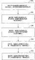
Fig. 2 to Fig. 4 illustrates the process flow diagram that several according to an embodiment of the invention use bending mode sensors signals and different touch location detection technology drew or optimized the method for touching position information;
Fig. 5 is the block diagram that the system that is used for realizing different touch location detection technology according to an embodiment of the invention is shown;
Fig. 6 illustrates the another kind of block diagram that is used for realizing the system of different touch location detection technology according to an embodiment of the invention;
Fig. 7 to Fig. 9 is the curve that a kind of cross section of touch panel systems according to an embodiment of the invention is shown, and wherein this touch panel systems has one or more being used for by using different touch location detection technology to realize the bending mode sensors of touch location detection; And
Figure 10 is the block diagram that is applicable to the touch-screen system of the touch location determination of realizing optimization according to an embodiment of the invention.
The present invention is suitable for various modifications and alternative form, and its details is shown in the drawings and will be described in detail by example.Yet should be appreciated that its purpose does not lie in is limited to described specific embodiment with the present invention.On the contrary, its purpose is to contain whole modifications, equivalent and the replacement scheme that meets in the scope defined by the claims.
Embodiment
Below in the explanation of example embodiment the accompanying drawing that constitutes this paper part being carried out reference, and show in the mode of example in the accompanying drawings and can realize various embodiment of the present invention.Should be appreciated that and under the situation that does not depart from the scope of the invention, can utilize these embodiment and make structural change.
The present invention relates to touch the user interaction device of actuating, and provide by the method for a plurality of touch sensors to the sensing of the vibration of process touch substrate propagation.The invention particularly relates to touch-sensing equipment and use configuration to come the method for sensing, wherein can use different touch location detection technology to judge touching position information according to described bending wave vibration by the sensor of the bending wave vibration that touches substrate and propagate.
The touch-sensing equipment of realizing according to the present invention may combine one or more of the feature described in the literary composition, structure, method or its combination.A kind of like this equipment or method do not need to comprise whole features and the function described in the literary composition, but can comprise combining and provide the selected feature and the function of the structure of usefulness and/or function.
Embodiments of the invention relate to multiple different touch localization process are combined the touch location of judging on the touch panel.Some embodiment described in the literary composition comprises the use that two or more is touched localization process, and wherein these touch localization process and utilize dissimilar touch location technologies.Other embodiment comprises the use that two or more is touched localization process, and wherein these touch the touch location technology that localization process is used same type, but it uses different maneuvers to judge touch location.
To touch touch on the substrate position comprise to the judgement of static touch location and/or to dynamically move touch such as in towing, retouch and draw or the judgement of employed action when writing operation.The dynamic touch measurement can comprise before the touch, touch during and/or touch flow data after finishing.Touch information can comprise the touching position information on the plane, for example x and the y coordinate of touch location on flat panel.In addition, touch location determination can comprise obtaining the z axis information.Z axle touch information can comprise, for instance, touches and/or breaks away from distance on detection, touch and/or second cosmic velocity, the touch panel and/or the touch pressure grade on the touch panel.Touch information can also comprise and be used for differentiate having a mind to and the information of touch event (for example wrong/correct touch recognition, anti-false touch measure) and the information that is used to realize touching arousal function unintentionally.
Noise in the touch signal can cause the touch location determination out of true.For instance, noise may be by electrostatic charge, electromagnetic interference (EMI), vibration, moment of torsion, surround lighting, noise, sound noise, surface contamination and/or gas noise source from display unit.Concerning touching localization process, it is important factor that noise is got rid of.It is lower for the noise sensitivity from particular source that some touches localization process.In certain embodiments, multiple touch localization process is combined to improve noise resisting ability.
Touch localization process and be associated with various processing parameters, precision, the resolution of measurement, the speed that obtains measurement result and the touch resource of measuring such as touch location that localization process consumed be power or shared processor time for example.Single touch localization process can provide outstanding performance at a parameter of above-mentioned touch location.Yet single touch localization process possibly can't become measures the optimal case that all touches parameter under all conditions.
Shown in the inventive embodiment as described herein, the combination that touches localization process can be advantageously used in the outstanding performance of obtaining at one or more above-mentioned parameters.For example, can get up the information combination that derives from two or more touch localization process to optimize one or more above-mentioned processing parameters or other processing parameter.A plurality of results that are used to judge the independent processing of touch location are combined can provide the many advantages that are better than only using single processing.The assembled scheme of the touch location determination described in the literary composition can provide any or whole following advantages: for example, and the noise resisting ability of the power consumption of the touch location Calculation complexity of the touch bearing accuracy of raising, reduction, the touch location determination speed of raising, reduction, the touch location-sensitive degree of raising, enhancing and/or the z axis information that strengthens.
Term " bending wave vibration " is meant the excitation that is for example caused by touch, its to can the support bends ripple parts of vibration cause certain out-of-plane displacement.A lot of materials can be crooked, and the some of them material has the pure bending of complete root dispersion relation, also has some materials to have the mixing of pure bending and shear-bow.Described dispersion relation is described the dependence of ripple speed planar for wave frequency.Out-of-plane displacement or deflection when term " bending " also can be applied to parts and bears load are such as when deflection (for example warpage archwise) takes place in response to being applied to its lip-deep touch in touch panel.About this point, a surface of touch panel is in compressive state, be in extended state with its facing surfaces simultaneously, thereby it is arc to cause touch panel to bend to.By the bending mode sensors that uses type described herein and this type of bending that can detect touch panel according to the mode of hereinafter being discussed.
For instance, in comprising the vibration sensing touch input equipment of piezoelectric transducer, the vibration of propagating in the plane of touch panel can be pushed piezoelectric transducer, can detected voltage thereby produce on sensor.The signal that is received can also can be produced by the touch input to existing vibration influential (for example making vibration damping) by direct touch input or owing to retouch the vibration generation that the energy input of stroke (friction) is directly caused.The signal that is received also can be the operation of touch input device or maloperation are caused such as the user by unexpected input or generate but input that the input equipment that is touched senses is produced by the ambient source of outside.
Referring now to Fig. 1, wherein show a kind of configuration of touch-sensitive device 100, it incorporates feature and the function that has by using multiple different touch location detection technology to detect bending wave vibration and judge touch location into.According to this embodiment, touch-sensitive device 100 comprises the vibration transducer 130 that touches substrate 120 and be coupled to touch substrate 120 upper surfaces.In this example, touch the upper surface qualification touch sensitive surface of substrate 120.Although sensor 130 is illustrated as being coupled to the upper surface that touches substrate 120, sensor 130 also can be coupled to the lower surface that touches substrate 120.In another embodiment, one or more sensors 130 can be coupled to the upper surface that touches substrate 120, and another one or a plurality of sensor 130 can be coupled to the lower surface that touches substrate 120 simultaneously.Vibration transducer 130A-130D can be coupled to touch pad 120 by any suitable means, for example use bonding, scolder or other suitable material, as long as the mechanical connection that is obtained is enough to make the vibration of propagating in the touch pad to be detected by vibration transducer.In commonly assigned (co-assigned) U.S. Patent application USSN 10/440,650 and USSN 10/739,471, disclose example vibration transducer and vibration transducer and arranged, its by reference integral body incorporate this paper into.
On the whole, touch-sensitive device 100 comprises that at least 3 sensors 130 are to judge the two-dimensional position that touches input, and may need 4 sensors 130 (in Fig. 1, being shown 130A, 130B, 130C and 130D) in certain embodiments, as open WO2003/005292 and WO 01/48684 and commonly assigned U.S. Patent application 09/746 in the world, discussed in 405, its by reference integral body incorporate this paper into.
In the present invention, sensor 130 preferably can the sensing indication touch the piezoelectric transducer that the touch on the substrate 120 is imported.Available piezoelectric transducer comprises single piezoelectric chip and bimorph piezoelectric transducer.Piezoelectric transducer can provide multiple favorable characteristics, for example comprises: good sensitivity, low relatively cost, enough robustnesss, potential less form factor, enough stability and linear responses.Other sensor that can be used in the vibration sensing touch sensitive equipment 100 comprises: electrostriction type, magnetostriction type, resistance pressure type, acoustic type, capacitor type and moving coil type sensor/device etc.
In one embodiment, all sensors 130 is configured to the vibration in the sensing touch substrate 120.Sensor 130 can be basic identical on technology and function.For example, all the sensors 130 can be by having of particular manufacturer the production identical part number or the bending mode sensors of sign.In other embodiments, sensor 130 can be basic identical technically, but the function difference.For example, all the sensors 130 can be the bending mode sensors of being produced by particular manufacturer, and the some of them sensor is used to detect flexural wave and other sensor is used for the check-out console reflection.In certain embodiments, one or more sensors 130 can be the sensors that is different from bending mode sensors.
According to another one embodiment, one or more sensors 130 can be used as ballistic device, the signal that its emission can be sensed by other sensor 130 is with used as reference signal, perhaps produce the vibration that the input that can be touched changes, reformed like this vibration can be sensed the position that touches to judge by sensor 130.The electrodynamic type sensor can be used as suitable ballistic device.In addition, one or more sensors 130 can be configured to double-purpose sensing stimulus sensor, the open WO 2003/005292 in the world and WO 01/48684 and the commonly assigned U.S. Patent application 10/750 of for example formerly incorporating this paper into, disclosed example in 502, described open and apply for that integral body is incorporated this paper into by reference.
The application of a lot of use touch-sensitive device 100 also uses electronic console to come by touch-sensitive device 100 display message.Because display is rectangle normally, the touch-sensitive device 100 of therefore using rectangle is typical cases and easily.Equally, the touch substrate 120 that is attached with sensor 130 is generally rectangle, although also can consider other geometric configuration.
According to a kind of configuration, sensor 130A, 130B, 130C and 130D preferably are arranged near on the angle that touches substrate 120.Because a lot of application needs are checked display frame by touch-sensitive device 100, therefore preferably sensor 130A-D is placed the edge that touches substrate 120, they just can not occupy visible display area like this.Sensor 130A-D is placed the influence that also can reduce on the angle that touches substrate 120 from the sound reflection of face plate edge.
The touch that touch-sensitive device 100 is sensed can be the form appearance with the contact pilotage contact, and this may be the form appearance with hand-held pen.Contact pilotage produces continuous signal in the athletic meeting that touches on the substrate 120, and it is subjected to contact pilotage in the influence that touches position, pressure and speed on the substrate 120.This contact pilotage may have for example rubber of elasticity tip, and it is touching in the substrate 120 by applying variable power to touch substrate 120 and is producing flexural wave.Described variable force is provided by the tip, and it alternately touches or slip over the surface that touches substrate 120.Another kind of scheme is, contact can be the form of finger touch, and it can produce flexural wave in touching substrate 120, and this flexural wave can be detected by passive and/or sensing initiatively.This flexural wave can have ultrasonic wave range (>20kHz) frequency component.
Touch-sensitive device 100 shown in Figure 1 can be connected to controller 150 communicatedly.Sensor 130A-D is via cable or be produced on and touch printing electrode pattern and be electrically connected to controller 150 on the substrate 120.Controller 150 generally includes to sensor 130 and signal is provided and signal or signal is changed the front-end circuit of measuring.In other configuration, controller 150 also comprises microprocessor outside front-end circuit.The controller 150 that hereinafter will describe in detail can be realized one or more touch location detection technology of selecting from different touch location detection technology banks.To the touch location detection Technology Selection can be according to the above discussion standard, and this selection can change according to the variation that touches drive characteristic, operating conditions, environmental baseline etc.
In a kind of Typical Disposition, touch-sensitive device 100 is used for display group with the mainframe computer system (not shown) provides visual haptic interaction between user and the mainframe computer system altogether.Mainframe computer system can comprise such as the communication interface of network interface so that communicate between touch panel systems that comprises touch-sensitive device 100 and remote system.For instance, the diagnosis of various touch panel systems, calibration and safeguard that routine can both realize by the collaboration communication between touch panel systems and the remote system.
Fig. 2 illustrates according to embodiments of the invention to use bending mode sensors signal and different touch location detection technology to draw the process flow diagram of the method for touching position information.Method shown in Figure 2 is included in the bending mode sensors that is coupled to touch sensitive surface is provided in 202.Multiple different touch location detection technology is provided in 204.The signal of at least a use bending mode sensors in these technology.In 206, use these different touch location detection technology to draw touching position information.
Draw touch location and can comprise judgement the touch location on the touch sensitive surface.At least some different touch location detection technology can detect touch location independently.For example, the first touch location detection technology can be judged x and the y coordinate of touch location with respect to touch sensitive surface, and the second touch location detection technology can be judged the z coordinate of relative touch sensitive surface.
Touching position information can include the information that is beneficial to the touch panel systems calibration or be applicable to the executive system diagnosis or the information of safeguarding.In certain embodiments, provide the touch location detection technology of two kinds of different uses at least by signal that bending mode sensors produces.For example, two or more touch location detection technology are used the signal that is produced by bending mode sensors, but they in frequency response or such as the speed of touch location measuring accuracy, Measurement Resolution, acquisition measurement result, touch on the characteristics such as resource consumption of localization process and differ from one another.
As other example, two or more touch location detection technology can differ from one another every kind of technology is handled in the mode that produces touching position information to the bending mode sensors signal on.In one embodiment, specific touch location detection technology may be handled to produce touching position information with two or more diverse ways bending wave signal.In another embodiment, two or more different touch location detection technology may be handled to produce touching position information bending wave signal with identical in fact method.
The flowchart text of Fig. 3 a kind of method of optimizing touching position information, wherein comprise use according to the bending mode sensors signal of the embodiment of the invention and different touch location detection technology.Method shown in Figure 3 comprises: provide multiple different touch location detection technology in 302, wherein at least a use bending mode sensors signal.In 304, use the first touch location detection technology to draw first group of touching position information.In 306, use first group of touching position information to optimize the touch location determination of making according to the second touch location detection technology.
Fig. 4 is the another kind of process flow diagram that draws the method for touching position information according to the bending mode sensors signal of the embodiment of the invention and different touch location detection technology that uses of explanation.Method shown in Figure 4 comprises: provide multiple different touch location detection technology in 402, wherein at least a use bending mode sensors signal.The first touch location detection technology provides first precision that is associated with touch location determination in 404.The second touch location detection technology provides second precision that is associated with touch location determination in 406.For instance, first technology provides the lower accuracy that touches the location, and second technology provides the degree of precision that touches the location.
In 408, use the first touch location detection technology to draw first group of touching position information.In 410, use the second touch location detection technology to draw second group of touching position information.For example, first technology can be used for estimating to take place in the touch sensitive surface zone of touch.Second technology can be used for providing the more accurate estimation to touch location in the zone of being estimated by first technology.
Fig. 5 is the block diagram that the system 500 that is used for realizing different touch location detection technology according to an embodiment of the invention is shown.As shown in Figure 5, system 500 comprises a plurality of bending mode sensors 501, and comprises the sensor 502 (for example, capacitor type, resistor-type, power, surface acoustic wave or optical sensor) of other type alternatively.Sensor 501,502 is connected to the touch sensitive surface (not shown) and is connected to controller 504.Controller 504 is configured to realize multiple different touch location detection technology (TLDT) 510, and these touch location detection technology 510 can be carried out access by the storer that is connected to controller 504.Controller 504 uses different touch location detection technology 510 to produce touching position information such as touch location.
For instance, technology TLDT-1 and technology TLDT-2 to TLDT-N are different aspect function discussed above and other.About this point, technology TLDT-1 is considered to the touch location detection technology different with technology TLDT-2 to TLDT-N.By other example, given technology can several means realize so that different touching position information to be provided, although every kind of technology is handled in a similar manner to the bending mode sensors signal such as technology TLDT-1.For example, TLDT-1 represents a kind of like this touch location detection technology, and it briefly carries out frequency analysis to the bending mode sensors signal.For example, technology TLDT-1A can realize analyzing being different from technology TLDT-1N associated frequency.Although every kind of technology is handled the bending mode sensors signal with common method, they generate different touch location detection information by the different qualities of analytic signal.Like this, technology TLDT-1A is considered to the touch location detection technology different with technology TLDT-1N.
Fig. 6 illustrates the another kind of block diagram that is used for realizing the system 600 of different touch location detection technology according to an embodiment of the invention.System 600 receives bending mode sensors signal 602, and receives the touch sensor signal 603 of other type alternatively.Controller 604 is configured to realize multiple different touch location detection technology 610-618.Controller 604 uses multiple different touch location detection technology 610-618 to produce touching position information.In a kind of scheme, controller 604 produces control signals 605, and it can be selected or cancel and select a kind of among the different touch location detection technology 610-618.According to embodiment shown in Figure 6, different touch location detection technology comprises that delta speed touches location technology 610, delta and touches location technology 612, the rate of curving time of arrival and touch location technology 614, frequency dispersion and proofread and correct and touch location technology 616 and iteration touches location technology 618.Now each that these are touched location technology 610-618 is elaborated.
Delta speed touches location technology 610 and is meant that a kind of phenomenon of vibration wave bag frequency dispersion of utilizing judges the technology that touches the touch location on the substrate.A kind of delta speed touches location technology 610 schemes and uses vibration wave bag frequency dispersion self to carry out range observation, therefrom can calculate touch location.Touch location technology 610 according to a kind of delta speed, the frequency dispersion vibration wave bag that is caused by the touch on the touch-sensitive substrate can be sensed by each vibration mode sensor.Each sensor all can detect the content of the ripple bag that comprises assigned frequency or multiple frequency.The relative time delay that the ripple bag content of calculating and assigned frequency or multiple frequency dependence connection arrives in each sensor.Use the distance of calculating this relative time delay between each sensor and the touch event.Use institute's calculated distance just can judge the position of touch then.
About this point, delta speed touches location technology 610 and only can be implemented as time of calculating the ripple stroke by the difference of using the ripple frequency dispersion and distance to measure touch location.The different frequency or the frequency range of vibration wave bag in the dispersive medium can be separated by numeral or analog filtering, thereby the time of arrival of each characteristic frequency or frequency range can be judged respectively.
According to another kind of scheme, can carry out cross correlation process to the vibration wave bag and the reference waveform that produce by touch event that has sensed, wherein said reference waveform produces by touching in each known location during calibration process.This cross correlation process can disclose the optimum matching with the specific waveforms that gives out from known position.Because the source of vibrational waveform is known, then can be according to the distance of the optimum matching of the disengaging time of energy that each frequency comprises being judged touch event.Be applicable to that this kind of the present invention and other delta speed touch common all USSN 11/025 that agency that the additional detail of location technology submits on Dec 29th, 2004 numbers NO.60084US002,389 and title be the US5 of " Touch LocationDeterminations Using Vibration Wave Packet Dispersion ", 635, provide explanation in 643, it incorporates this paper by reference into.
With reference to Fig. 6, delta touches location technology 612 time of arrival and comprises according to first energy and arrive the touch location determination that time of each bending mode sensors carries out.For example, when the energy on each sensor surpasses predetermined threshold value, can judge the time that arrives each sensor.Can use the difference of above-mentioned threshold energy on time of arrival to calculate initial touch such as the position of rapping.This technology 612 is unsuitable for measuring the position that touches continuously of moving such as towing.Yet, delta technology time of arrival can with compare other more the technology of robust processing simpler, more low energy consumption touch is measured.Position during other technology can be used for calculating the touch location of meticulousr (more accurate) and/or calculate drag operation.At US 5,691,959 and WO 01/48684 in delta technology time of arrival that is suitable for is had further instruction, US 5,691,959 and WO 01/48684 incorporate this paper by reference into.
The rate of curving shown in Figure 6 touches location technology 614 and uses plate bending to measure touch location in conjunction with the simple rate of amplitude measurements and calculated value.Fig. 7 illustrates the system 740 that has overlayer 741 and sensor 742, wherein is in long wavelength's bending that the sensor 742 on each edge is measured overlayer 741.Sensor 742 can be expanded on whole length at each edge or partial-length.Panel 741 is attached to substrate 749 by support component 747 and 748 on the angle, wherein support component 747 and 748 vertical constraint panels 741.Overlayer 741 in the horizontal (for example in the plane of overlayer 741) be attached to substrate 749 edge 744 and 745 the constraint and can't move.
The basic half-wave oscillation frequency (under beam mode shown in Figure 7) of typical glass touch sensor is in the scope of 50Hz to 1K Hz, depends on thickness of glass, edge length and lag characteristic.Therefore finger touch will have ceiling capacity in the frequency of 5Hz to 1K Hz, by measuring senses touch can obtain good signal near half-wave beam mode frequency place or its.With compare near the measurement of static (0 to 10Hz), the signal in this frequency range is measured the lag-effect that can reduce the parts 744,745,747 that are used for retraining panel 741 and 748 and non-linear.
Continuation is with reference to Fig. 6, and frequency dispersion is proofreaied and correct touch location technology 616 and can be used for using the beam mode signal to draw touching position information.When propagation medium was frequency dispersion type medium, the vibration wave bag of being made up of multiple frequency can scatter and come and decay along with propagation, thereby made the deciphering of the signal difficulty that becomes.Like this, need change, make it as in non-frequency dispersion type medium, propagating and to be understood to received signal.Open WO 2003/005292 and WO01/48684 and US 6 in the world, 871, disclose in 149 and be used for determining vibration wave bag frequency dispersion and being used to produce the example technique of having carried out the representation signal of correction at this type of frequency dispersion, WO2003/005292 and WO 01/48684 and US 6, incorporate this paper in 871,149 by reference into.
According to a kind of scheme of proofreading and correct vibration wave bag frequency dispersion of operating, for instance, be installed in structural first bending mode sensors that to support flexural wave and measure the first measurement bending wave signal.Second bending mode sensors is installed on this structure to judge that second measures bending wave signal.The second measurement bending wave signal and first is measured bending wave signal and is measured simultaneously.Calculate the frequency dispersion correction function of two measured bending wave signals, this function may be related function, the convolution function that frequency dispersion is proofreaied and correct, the coherence function of frequency dispersion correction or other the phase transformation balance function that frequency dispersion is proofreaied and correct.The bending wave signal that measures is handled to calculate by the function of using the frequency dispersion correction and to touch relevant information.Formerly incorporate into and disclose the relevant details of scheme therewith among the WO 2003/005292 of this paper and WO 01/48684 and the US 6,871,149.
Fig. 8 illustrates a kind of overlayer 821, and it has the beam mode piezoelectric sensor 822 and 823 of the vibration that is in sonic frequency usually that can measure overlayer 821.Time after the frequency-correction of sound wave stroke can calculate touch location.Compliance suspension 824 also can be used as liner, and acoustical signal that can damping overlayer 821 edges.In another example, can use a kind of Time-Domain Technique (no matter its whether adopt frequency dispersion proofread and correct) to produce initial position message, and a kind of technology of operating according to phase differential can be used for the initial position message that refinement is produced by described Time-Domain Technique.
Iteration as shown in Figure 6 touches the ability that location technology 618 can provide multiple enhancing.For example, the rough touch location that uses simple computation to obtain can be used to carry out more accurate touch location analysis via iterative processing.Rough or middle touch location can be used for iteration and adjust sensor signal, thereby can improve the precision of simple computation.
Other touch localization method is the intrinsic accuracy of employed touch location technology to the judgement precision of touch location.Iteration touches the ability that location technology 618 provides the accurate reproduction of iterative approach source waveform.Like this, use this iterative technique can make the judgement of touch location arrive desired or required degree of accuracy.
As example, produce the touch location signal in response to the vibration that touch produced on the touch pad by for example above-mentioned processing.Judge and obtain rough touch location.This rough touch location can be optional position, can be based on the signal that is produced, and perhaps can be to obtain by other method is approximate.In a kind of scheme, can use the first touch location technology to obtain touch location roughly, and use the second touch location technology to judge touch location more accurately by iterative processing.
Adjust the signal that is produced based on rough touch location.Come calculated touch location according to adjusted signal.Can use the middle touch location continuation iteration of new judgement to come signal is adjusted once more, recomputate touch location arbitrarily iterations.Iterative processing can be repeated a plurality of circulations to obtain desired or required precision.When the cycle index that requires is finished or when obtaining desired precision, stop touching location algorithm, return the final touch location of judging by iterative processing.The agency who submits on January 10th, 2005 numbers the common all USSN 11/032 of NO.60083US002 title for " Iterative Method for Determining TouchLocation ", the example of iteration touch location technology 618 has been described, above-mentioned open this paper that incorporates into by reference in 572.
Following example explanation uses multiple different touch location technology to generate touching position information according to embodiments of the invention.According to a kind of scheme, the low frequency measurement of panel bending and rate of curving analysis (for example the rate of curving touches location technology 614) can combine the pretty good rough and accurate touch location of realization with audio frequency frequency dispersion correcting measuring and frequency-domain analysis (for example frequency dispersion is proofreaied and correct and touched location technology 616) and measure.
Fig. 9 illustrates the system 960 that has overlayer 961 and have sensor 962 and 963 on each angle.Sensor 962 and 963 bendings of measuring overlayer 961.When being used in combination frequency dispersion correction touch location technology 616 and rate of curving touch location technology 614, sensor 962 and 963 preferably can be measured the identical sensor of audio frequency vibration.Compliance suspension 964 is the bands around panel 961 peripheries.Suspension 964 is preferably as the liner of touch system, and its damping characteristic must can satisfy specific frequency dispersion and proofread and correct the audio request that touches location technology 616, and the low frequency plate bending requirement of specific curvature rate touch location technology 614.Suspension 964 can shown in end face, bottom surface or two faces on touch panel 961.
As before discussing, the basic half-wave beam mode frequency of the vibration of typical glass touch sensor is in the scope of 50Hz to 1K Hz, and finger touch will have ceiling capacity at 5Hz to 1K Hz.Like this, by measuring senses touch can obtain good signal near half-wave beam mode frequency place or its.As before discussing equally, and compare near the measurement of static (0 to 10Hz), the signal in this low frequency beam mode scope (50Hz to 1K Hz) is measured lag-effect in the elastic constant that can reduce suspension 964 and non-linear.Bending system shown in Figure 9 also can relatively be avoided the influence of large tracts of land " noise " force rate such as airborne sound wave.Yet resolution and precision can be subjected to the restriction that can't measure (error) power that process suspension 964 transmits between panel 961 and substrate 969.They comprise the inhomogeneous bending force that causes by the deflection of substrate and suspension 964.
Some touch location detection technology is applicable to the rough touch location of judging on the touch-sensitive substrate more, and other touch location detection technology are more suitable for judging the accurate touch location on the touch-sensitive substrate.The method that illustrates below comprises uses one of several technology to judge rough touch location, also comprises and uses one of several other technology to judge accurate touch location.
Steps A-find out rough touch location by one of following several method:
1, measures relative delta time of arrival (for example technology 612) of time-base waveform.For example, measure the time that energy on each sensor (for the first time) surpasses threshold value.Surpass difference on time of arrival of energy of threshold value and can be used for calculating rough position.This rough scheme comprises than frequency dispersion correction touch location technology 616 simpler calculating for instance, and can less time and the realization of processing power still less.
2, the frequency dispersion amount (for example receiving the delay of 3KHz energy when receiving the 15KHz energy) that has received waveform can be used for calculating the wave propagation time, because frequency dispersion and time proportional (for example delta speed touch location technology 610).By using simple measurement and just can judging rough position, draw accurate position by the method in following " fine location " option then to the calculating of this frequency dispersion difference.
3, static state/low frequency plate bending signal can be used for producing rough touch location by above-mentioned about rate of curving touch location technology 616.The sensor that panel, panel suspension and being used to measured Lamb wave sound signal (for example frequency dispersion is proofreaied and correct and touched location technology 616) also can be used for measuring low frequency plate bending signal.This allows the signal (for example, the rate of curving and frequency dispersion are proofreaied and correct, and it all uses flexural wave in the frequency range of separating, and has different range observation standards) of two types of single sensor measurements of organizing.Different signal type (and different computing techniques) can combine realization can obtainable better result than single method.
4, iteration touch location technology 618 can be used to produce rough position, and is as indicated above.This method use has multiplephase the iterative scheme (passively) of simple frequency-domain calculations is located touch location according to the sound data in the panel, and it is employed to touch location technology 616 such as the frequency dispersion correction.
A, repeatedly use this algorithm and can calculate and touch the required rough and meticulous precision in location, perhaps
B, once (or repeatedly) use this algorithm to calculate rough position according to the sound data, can use the position that the frequency dispersion correcting algorithm uses identical sound data to calculate meticulous (more high precision) then.
The frequency dispersion correcting algorithm of c, simplification (low resolution fast fourier transform or FFT) can be used on the sound data that measure to calculate rough position, and then once (or repeatedly) uses this iterative algorithm to come according to the identical accurate position of sound data computation.
Step B-draws more accurate position by the refinement of one of following several method:
1, can use a kind of iteration based on frequency domain touch location technology 618 to according to above-mentioned Time- Domain Technique 1,2 or 3 or the rough position that draws of above-mentioned frequency domain technique 4 carry out refinement, to obtain more high-precision position.
2, the touch of being undertaken by better simply time-based rough position measurement detects (according to above-mentioned processing 1,2 or 3) and can trigger known fft algorithm (for example iteration or frequency dispersion are proofreaied and correct), and fft algorithm can calculate comparatively accurate position.Move along with touch location is pulling/writing operating period, delta touch time of arrival location technology 612 and delta speed touch location technology 610 can be because the disappearance and the reflection interference of the disappearance of signal amplitude, signal variation be lost accuracy; Like this such as frequency dispersion proofread and correct 616 or iteration 618 scheduling algorithms can be used for following the tracks of position during the towing.
3, the rough touch location of time-based correction-provided:
A, calculate frequency dispersion (D) amount at each sensor place according to rough position.
B, be that each sensor generates the template T corresponding to this frequency dispersion amount
D(t).
C, then with frequency dispersion template T
D(t) carry out relevant treatment with the ripple that receives.
D, reach maximum positive correlation and confirm that then this frequency dispersion (and therefore to distance of touch point) all is correct for the sensor at each angle.
E, do not reach maximal correlation and then show and also need further error correction.
In some cases, obtaining touch coordinate, to be accurate to 5% to 20% rough position just enough, for example initial application that has the menu of 4 to 8 wide cut buttons on display, and+/-20% precision just is enough to differentiate and has touched which button.Follow-up touch operation may need extra precision, therefore may need to adopt second kind to touch location technology.
As example, anti-false touch (as the touch of mistake) method can realize by different touch location detection technology.In one example, frequency dispersion alignment technique 616 (sound measurement after for example frequency dispersion is proofreaied and correct) and rate of curving technology 614 (for example static state/low frequency plate bending is measured) can combine the anti-false touch method that realizes.
The touch panel that is used to write input can have two touch points; One is the hand that rests on the panel, and another is the stylus tip that is used to write.When using frequency dispersion bearing calibration measurement contact pin position, know that the position of hand is favourable.Hand can produce acoustic energy, and can absorb the energy that is produced during writing by contact pilotage with antireflection part, especially under the situation of bigger hand pressure.Can locate moving and the position of contact pilotage most effectively by measuring higher acoustic frequency.When hand moves, can measure the combination (being generally lower frequency) of acoustical signal individually, when hand rests on the clipboard surface, carry out the very low frequency (VLF) rate of curving and measure, to get position in one's hands.
Signal that the adversary produced and hand can improve the precision that stylus position is measured to the compensation of the influence of contact pilotage signal.
1, when using contact pilotage to write, from the reflection of hand with sound noise can be left in the basket or initiatively get rid of by (some very complexity) calculating.
If 2 detect existence in one's hands between contact pilotage and an angle, then the signal after iteration that receives on this angle or frequency dispersion correction can be left in the basket (position calculation does not generally need the signal on whole 4 angles) or be modified.
Use bending mode sensors and multiple different touch location detection technology can realize touching and wake or touch confirmation method up.For example, touch awakening method and comprise importing the sensing of the bending wave vibration that touches substrate, and be by causing and judge touching the touch that substrate has a mind to or touching institute unintentionally to this type of ripple vibration.Some can use the touch difference of different touch tool or different touching intensity to come with other to the touch that touches substrate, wakes touch signal up so have only specific having a mind to touch to be detected as.Disclose the details of various touch awakening methods in the U.S. Patent application of submitting on October 10th, 2,003 10/683,342, it incorporates this paper by reference into.Various relating to, break away to be detected and the details of the method for the improvement susceptibility of light contact be illustrated in common all USSN 10/750,291, and it incorporates this paper by reference into.
As further example, can use a kind of Low-power Technology to wake (energising) main touch measuring system up, and can use another kind (more high-power) technology to measure touch location.In these different technology each is all preferably used bending mode sensors.Time-based technology, such as delta location technology time of arrival 612, delta speed location technology 610 and rate of curving location technology 614, ratio is lower based on method such as the frequency dispersion correction location technology 616 desired processing powers of FFT, and therefore time-based method can be used to wake up touch detection processing.
Referring now to Figure 10, wherein show a kind of according to an embodiment of the invention embodiment that is applicable to the touch-screen system of the touch location determination of realizing optimization.Touch system 1020 shown in Figure 10 comprises touch panel 1022, and it can be connected to controller 1026 communicatedly.Controller 1026 is included as touch panel 1022 at least and signal is provided, measures the variation of touch signal or touch signal and realizes that two or more different touch location detection technology are to produce the circuit 1025 (for example front-end circuit) of touching position information.In the structure of robust more, controller 1026 also further comprises microprocessor 1027 outside front-end circuit 1025.In a kind of typical configuration, touch panel 1022 is used for combining with the display 1024 of host computer system 1028, provides visual haptic interaction between user and host computer system 1028.
Be appreciated that touch panel 1022 can realize as the equipment that separates with the display 1024 of host computer system 1028 but cooperate with it.Another kind of scheme is that the part that touch panel 1022 can be used as triangular web realizes that wherein this triangular web comprises the display device that can incorporate touch panel 1022 into such as plasma, LCD or other type display technique.It is also understood that and can use a kind of like this system, it is defined as including only sensor 1022 and controller 1026, and wherein sensor 1022 and controller 1026 can combine realization touch detection scheme of the present invention.
In example constructions shown in Figure 10, the communication between touch panel 1022 and the host computer system 1028 realizes via controller 1026.Notice that one or more controllers 1026 can be connected to one or more touch panels 1022 and host computer system 1028 communicatedly.Controller 1026 has the typical construction that is applied to the firmware/software of the touch detection on the touch panel 1022 in order to execution, and it comprises the error correction that principle according to the present invention is carried out the motion on the touch panel.Should be appreciated that function or the program carried out by controller 1026 can be realized by the processor or the controller either-or of host computer system 1028.
Above-mentioned description to various embodiments of the invention is used for example and illustrative purposes.It has no intention to carry out exhaustive or the present invention is limited to disclosed exact form.Can carry out a variety of modifications and change according to above-mentioned guidance.Scope of the present invention is subjected to claims but not the restriction of this detailed description.
Claims (15)
1. touch-sensitive device comprises:
A plurality of touch sensors are that its touch sensitive surface that is configured to the senses touch substrate causes owing to the touch to it and by touching the bending wave vibration that substrate is propagated; And
Treatment circuit, it is configured to realize the first different touch location detection technology and the second touch location detection technology, realize that wherein these touch location detection technology use the signal that is generated by a plurality of touch sensors, treatment circuit also is configured to draw touching position information by using the touching position information that is associated with the first touch location detection technology to optimize the touch location determination that is undertaken by the second touch location detection technology.
2. equipment as claimed in claim 1, in wherein said a plurality of touch sensor at least one be to the first frequency range-sensitive, and other touch sensor of at least one in described a plurality of touch sensors is to being different from the second frequency range-sensitive of first frequency scope.
3. equipment as claimed in claim 1, at least a to the first frequency range-sensitive in the wherein said multiple different touch location detection technology, at least a other the touch location detection technology in the described multiple different touch location detection technology is to being different from the second frequency range-sensitive of first frequency scope.
4. equipment as claimed in claim 1, wherein a plurality of touch sensors are to identical frequency range sensitivity.
5. equipment as claimed in claim 1, at least some in the wherein said multiple different touch location detection technology are the senses touch position independently.
6. equipment as claimed in claim 1, wherein said touching position information comprises the touch location on the touch sensitive surface.
7. equipment as claimed in claim 1, wherein said touching position information comprise the z coordinate of this touch with respect to touch sensitive surface.
8. equipment as claimed in claim 1, wherein said touching position information comprises the dynamics of the touch on the touch sensitive surface.
9. equipment as claimed in claim 1, at least some technology in the wherein said multiple different touch location detection technology are used and are drawn touching position information by the flexural wave that some sensor sensed in described a plurality of touch sensors.
10. equipment as claimed in claim 1, at least some technology in the wherein said multiple different touch location detection technology use the displacement by the touch sensitive surface that at least one sensed in described a plurality of touch sensors to draw touching position information.
11. equipment as claimed in claim 1, wherein said treatment circuit is configured to by using first touch detection technical in the described multiple touch detection technical to confirm touch on touch sensitive surface, and by using second touch detection technical in the described multiple touch detection technical to judge touch location on touch sensitive surface.
12. equipment as claimed in claim 1, wherein said multiple different touch location detection technology comprises:
The first touch location detection technology, it judges x and the y coordinate of touch location with respect to touch sensitive surface; And
The second touch location detection technology, it judges the z coordinate of touch location with respect to touch sensitive surface.
13. equipment as claimed in claim 1, wherein said multiple different touch location detection technology comprises: at least a touch location detection technology, it provides being proofreaied and correct by the frequency dispersion of the signal that at least one generated in a plurality of bending mode sensors.
14. equipment as claimed in claim 1, wherein treatment circuit is further configured to using at least a in the multiple touch location detection technology to come at least in part to draw touching position information according to the displacement of touch sensitive surface and by the journey time of the flexural wave that touch produced on the touch sensitive surface.
15. a touch-sensing method comprises:
Use a plurality of bending mode sensors, wherein each bending mode sensors all is coupled to the touch sensitive surface of touch substrate to produce signal in response to the bending wave vibration of propagating by the touch substrate; And
Use the first different touch location detection technology and the second touch location detection technology, wherein at least a use in the first touch location detection technology and the second touch location detection technology is used the touching position information that is associated with the first touch location detection technology to optimize the touch location determination that is undertaken by the second touch location detection technology and is drawn touching position information by the signal of bending mode sensors generation.
Applications Claiming Priority (2)
| Application Number | Priority Date | Filing Date | Title |
|---|---|---|---|
| US11/116,463 US7683890B2 (en) | 2005-04-28 | 2005-04-28 | Touch location determination using bending mode sensors and multiple detection techniques |
| US11/116,463 | 2005-04-28 |
Publications (2)
| Publication Number | Publication Date |
|---|---|
| CN101171566A CN101171566A (en) | 2008-04-30 |
| CN100549925C true CN100549925C (en) | 2009-10-14 |
Family
ID=36754208
Family Applications (1)
| Application Number | Title | Priority Date | Filing Date |
|---|---|---|---|
| CNB200680014806XA Expired - Fee Related CN100549925C (en) | 2005-04-28 | 2006-04-21 | Touch-sensitive device and touch-sensing method |
Country Status (7)
| Country | Link |
|---|---|
| US (1) | US7683890B2 (en) |
| EP (1) | EP1875330A2 (en) |
| JP (1) | JP2008539514A (en) |
| KR (1) | KR20080005990A (en) |
| CN (1) | CN100549925C (en) |
| TW (1) | TW200710705A (en) |
| WO (1) | WO2006115947A2 (en) |
Families Citing this family (94)
| Publication number | Priority date | Publication date | Assignee | Title |
|---|---|---|---|---|
| US9019209B2 (en) | 2005-06-08 | 2015-04-28 | 3M Innovative Properties Company | Touch location determination involving multiple touch location processes |
| US20070188474A1 (en) * | 2006-02-16 | 2007-08-16 | Zaborowski Philippe S | Touch-sensitive motion device |
| US8780053B2 (en) * | 2007-03-21 | 2014-07-15 | Northwestern University | Vibrating substrate for haptic interface |
| US8525778B2 (en) | 2007-03-21 | 2013-09-03 | Northwestern University | Haptic device with controlled traction forces |
| JP4578451B2 (en) * | 2006-09-15 | 2010-11-10 | 京セラ株式会社 | Electronics |
| FR2909208B1 (en) * | 2006-11-29 | 2009-05-08 | Xavier Ferreira | PRODUCT SALES DISPLAY DEVICE. |
| US8493332B2 (en) * | 2007-06-21 | 2013-07-23 | Elo Touch Solutions, Inc. | Method and system for calibrating an acoustic touchscreen |
| US8730213B2 (en) * | 2007-07-02 | 2014-05-20 | Elo Touch Solutions, Inc. | Method and system for detecting touch events based on redundant validation |
| US8378974B2 (en) * | 2007-07-02 | 2013-02-19 | Elo Touch Solutions, Inc. | Method and system for detecting touch events based on magnitude ratios |
| KR101345755B1 (en) | 2007-09-11 | 2013-12-27 | 삼성전자주식회사 | Apparatus and method for controlling operation in a mobile terminal |
| US8059103B2 (en) * | 2007-11-21 | 2011-11-15 | 3M Innovative Properties Company | System and method for determining touch positions based on position-dependent electrical charges |
| US9367166B1 (en) * | 2007-12-21 | 2016-06-14 | Cypress Semiconductor Corporation | System and method of visualizing capacitance sensing system operation |
| US8170713B2 (en) * | 2008-03-06 | 2012-05-01 | Coin Acceptors, Inc. | Method of selecting a product from a refrigerated glass front vending machine |
| EP2104023A3 (en) * | 2008-03-18 | 2012-08-22 | Anders Swedin | Method and apparatus at a touch sensitive device |
| US8077159B2 (en) * | 2008-07-15 | 2011-12-13 | 3M Innovative Properties Company | Systems and methods for correction of variations in speed of signal propagation through a touch contact surface |
| US8264364B2 (en) * | 2008-09-08 | 2012-09-11 | Phillip Roger Sprague | Psychophysiological touch screen stress analyzer |
| US8183875B2 (en) * | 2008-11-26 | 2012-05-22 | 3M Innovative Properties Company | System and method for determining touch positions based on passively-induced position-dependent electrical charges |
| GB2468275A (en) * | 2009-02-16 | 2010-09-08 | New Transducers Ltd | A method of making a touch-sensitive data entry screen with haptic feedback |
| CN101840279B (en) * | 2009-03-18 | 2012-08-22 | 宏碁股份有限公司 | Method for correcting flexible plate |
| CN102439549A (en) | 2009-04-06 | 2012-05-02 | 3M创新有限公司 | Touch sensor with modular sensing components |
| CN102388353A (en) * | 2009-04-09 | 2012-03-21 | 新型转换器有限公司 | Touch sensitive device |
| US20100295813A1 (en) * | 2009-05-22 | 2010-11-25 | Tyco Electronics Corporation | System and method for a projected capacitive touchscreen having grouped electrodes |
| DE112010002072T5 (en) * | 2009-05-22 | 2012-10-11 | Semiconductor Components Industries, Llc | A method and apparatus for detecting a hold condition on an acoustic touch surface |
| US8279194B2 (en) * | 2009-05-22 | 2012-10-02 | Elo Touch Solutions, Inc. | Electrode configurations for projected capacitive touch screen |
| TWI392870B (en) * | 2009-06-30 | 2013-04-11 | Hon Hai Prec Ind Co Ltd | Sensing device |
| US8477106B2 (en) * | 2009-07-29 | 2013-07-02 | Elo Touch Solutions, Inc. | System and method for a projected capacitive touchscreen having weight based coordinate determination |
| US8325160B2 (en) * | 2009-09-11 | 2012-12-04 | 3M Innovative Properties Company | Contact sensitive device for detecting temporally overlapping traces |
| CN102025814A (en) * | 2009-09-11 | 2011-04-20 | 深圳富泰宏精密工业有限公司 | Portable electronic device |
| US9696856B2 (en) | 2009-09-29 | 2017-07-04 | Elo Touch Solutions, Inc. | Method and apparatus for detecting simultaneous touch events on a bending-wave touchscreen |
| JP5284924B2 (en) * | 2009-10-30 | 2013-09-11 | 富士通フロンテック株式会社 | Touch panel type input device and object leaving detection method |
| US8181140B2 (en) * | 2009-11-09 | 2012-05-15 | Xilinx, Inc. | T-coil network design for improved bandwidth and electrostatic discharge immunity |
| US20110260988A1 (en) * | 2010-01-20 | 2011-10-27 | Northwestern University | Method and apparatus for increasing magnitude and frequency of forces applied to a bare finger on a haptic surface |
| US8587422B2 (en) | 2010-03-31 | 2013-11-19 | Tk Holdings, Inc. | Occupant sensing system |
| US9007190B2 (en) | 2010-03-31 | 2015-04-14 | Tk Holdings Inc. | Steering wheel sensors |
| JP5759230B2 (en) | 2010-04-02 | 2015-08-05 | ティーケー ホールディングス,インコーポレーテッド | Steering wheel with hand sensor |
| EP2572260B1 (en) * | 2010-05-21 | 2019-12-04 | Nokia Technologies Oy | A method, an apparatus and a computer program for controlling an output from a display of an apparatus |
| US8941623B2 (en) * | 2010-07-27 | 2015-01-27 | Motorola Mobility Llc | Methods and devices for determining user input location based on device support configuration |
| CN102478984A (en) * | 2010-11-30 | 2012-05-30 | 汉王科技股份有限公司 | Piezoelectric positioning electronic device capable of reducing noise interference |
| DE102011002852B4 (en) * | 2011-01-19 | 2024-04-11 | Preh Gmbh | Operating device with operator-dependent switching functionality and associated procedure |
| JP5639489B2 (en) * | 2011-01-25 | 2014-12-10 | キヤノン株式会社 | Information processing apparatus, control method therefor, program, and storage medium |
| US10198097B2 (en) | 2011-04-26 | 2019-02-05 | Sentons Inc. | Detecting touch input force |
| US11327599B2 (en) | 2011-04-26 | 2022-05-10 | Sentons Inc. | Identifying a contact type |
| US9477350B2 (en) | 2011-04-26 | 2016-10-25 | Sentons Inc. | Method and apparatus for active ultrasonic touch devices |
| US9639213B2 (en) | 2011-04-26 | 2017-05-02 | Sentons Inc. | Using multiple signals to detect touch input |
| US9189109B2 (en) | 2012-07-18 | 2015-11-17 | Sentons Inc. | Detection of type of object used to provide a touch contact input |
| US10007341B2 (en) | 2011-06-21 | 2018-06-26 | Northwestern University | Touch interface device and method for applying lateral forces on a human appendage |
| TWI421481B (en) * | 2011-06-24 | 2014-01-01 | Universal Cement Corp | Preloaded pressure sensor module |
| US8319746B1 (en) | 2011-07-22 | 2012-11-27 | Google Inc. | Systems and methods for removing electrical noise from a touchpad signal |
| TWI444587B (en) | 2011-08-03 | 2014-07-11 | Nat Univ Tsing Hua | Curvature sensing structure without dissipation energy and method thereof |
| TW201316240A (en) * | 2011-10-06 | 2013-04-16 | Rich Ip Technology Inc | Touch processing method and system using graphic user interface image |
| US9081448B2 (en) | 2011-11-04 | 2015-07-14 | 3M Innovative Properties Company | Digitizer using multiple stylus sensing techniques |
| KR101850680B1 (en) | 2011-11-18 | 2018-04-20 | 센톤스 아이엔씨. | Detecting touch input force |
| US10235004B1 (en) | 2011-11-18 | 2019-03-19 | Sentons Inc. | Touch input detector with an integrated antenna |
| EP2780782B1 (en) | 2011-11-18 | 2020-05-13 | Sentons Inc. | Localized haptic feedback |
| US11340124B2 (en) | 2017-08-14 | 2022-05-24 | Sentons Inc. | Piezoresistive sensor for detecting a physical disturbance |
| TWI467428B (en) * | 2011-11-30 | 2015-01-01 | Top Victory Invest Ltd | Electronic system, touch device, control circuit and touch processing method |
| TWI502403B (en) | 2011-12-27 | 2015-10-01 | Ind Tech Res Inst | Flexible display and controlling method therefor |
| CN103365455B (en) * | 2012-04-09 | 2016-06-01 | 群康科技(深圳)有限公司 | Curved surface sense of touch feedback Touch Screen and sense of touch feedback driving method thereof |
| WO2013154720A1 (en) | 2012-04-13 | 2013-10-17 | Tk Holdings Inc. | Pressure sensor including a pressure sensitive material for use with control systems and methods of using the same |
| DE112013002288T5 (en) * | 2012-05-03 | 2015-04-16 | Apple Inc. | Moment compensated bending beam sensor for load measurement on a bending beam supported platform |
| US9348468B2 (en) | 2013-06-07 | 2016-05-24 | Sentons Inc. | Detecting multi-touch inputs |
| US9632606B1 (en) | 2012-07-23 | 2017-04-25 | Parade Technologies, Ltd. | Iteratively adjusting estimated touch geometries of estimated touches to sequential estimated actual touches |
| JP5907429B2 (en) * | 2012-07-24 | 2016-04-26 | 日本電気硝子株式会社 | Plate-like warpage inspection apparatus and warpage inspection method thereof |
| US9696223B2 (en) | 2012-09-17 | 2017-07-04 | Tk Holdings Inc. | Single layer force sensor |
| CN104756469B (en) * | 2012-11-07 | 2017-08-25 | 株式会社村田制作所 | Wake-up signal generation device, touch input unit |
| CN103076914B (en) * | 2012-12-20 | 2015-10-28 | 杜朝亮 | A kind of touch location based on energy distribution vector ratio and energy measuring method |
| US9507464B2 (en) * | 2013-03-15 | 2016-11-29 | Elo Touch Solutions, Inc. | Acoustic touch apparatus and methods using touch sensitive lamb waves |
| US9513663B2 (en) | 2013-04-02 | 2016-12-06 | Apple Inc. | Electronic device with touch sensitive display |
| JP5751276B2 (en) * | 2013-04-26 | 2015-07-22 | カシオ計算機株式会社 | Information processing apparatus, information processing method, and program |
| KR101815006B1 (en) * | 2013-05-13 | 2018-01-09 | 삼성전자주식회사 | Apparatus and method for sensing bending and touch using optical waveguide |
| KR20150010516A (en) * | 2013-07-19 | 2015-01-28 | 삼성전자주식회사 | Method and apparatus for displaying object by flexible device |
| WO2015041640A2 (en) * | 2013-09-18 | 2015-03-26 | Empire Technology Development Llc | Flexible surface acoustic wave touchscreen |
| US9601085B2 (en) * | 2013-09-20 | 2017-03-21 | Synaptics Incorporated | Device and method for synchronizing display and touch controller with host polling |
| US9459715B1 (en) | 2013-09-20 | 2016-10-04 | Sentons Inc. | Using spectral control in detecting touch input |
| US9817521B2 (en) | 2013-11-02 | 2017-11-14 | At&T Intellectual Property I, L.P. | Gesture detection |
| US10025431B2 (en) | 2013-11-13 | 2018-07-17 | At&T Intellectual Property I, L.P. | Gesture detection |
| KR101500268B1 (en) * | 2014-04-04 | 2015-03-06 | 현대자동차주식회사 | Variable mounting sound wave touch pad |
| CN106716320B (en) | 2014-09-30 | 2020-10-30 | 苹果公司 | Configurable force-sensitive input structure for electronic devices |
| US9830030B2 (en) | 2015-05-07 | 2017-11-28 | Industrial Technology Research Institute | Flexible touch panel, touch control device and operating method using the same |
| US10296047B2 (en) | 2015-08-04 | 2019-05-21 | Apple Inc. | Input mechanism with deformable touch-sensitive material |
| US10048811B2 (en) | 2015-09-18 | 2018-08-14 | Sentons Inc. | Detecting touch input provided by signal transmitting stylus |
| TWI649686B (en) | 2015-09-30 | 2019-02-01 | 美商蘋果公司 | Keyboard with adaptive input columns |
| US10409412B1 (en) | 2015-09-30 | 2019-09-10 | Apple Inc. | Multi-input element for electronic device |
| US10318065B2 (en) * | 2016-08-03 | 2019-06-11 | Apple Inc. | Input device having a dimensionally configurable input area |
| US10871860B1 (en) | 2016-09-19 | 2020-12-22 | Apple Inc. | Flexible sensor configured to detect user inputs |
| US10908741B2 (en) | 2016-11-10 | 2021-02-02 | Sentons Inc. | Touch input detection along device sidewall |
| US10296144B2 (en) | 2016-12-12 | 2019-05-21 | Sentons Inc. | Touch input detection with shared receivers |
| US10126877B1 (en) | 2017-02-01 | 2018-11-13 | Sentons Inc. | Update of reference data for touch input detection |
| US10585522B2 (en) | 2017-02-27 | 2020-03-10 | Sentons Inc. | Detection of non-touch inputs using a signature |
| US11157115B2 (en) | 2017-03-31 | 2021-10-26 | Apple Inc. | Composite cover material for sensitivity improvement of ultrasonic touch screens |
| US10732743B2 (en) | 2017-07-18 | 2020-08-04 | Apple Inc. | Concealable input region for an electronic device having microperforations |
| US11580829B2 (en) | 2017-08-14 | 2023-02-14 | Sentons Inc. | Dynamic feedback for haptics |
| US10732676B2 (en) | 2017-09-06 | 2020-08-04 | Apple Inc. | Illuminated device enclosure with dynamic trackpad |
| CN112256154A (en) * | 2020-11-04 | 2021-01-22 | 潍坊聚德电子有限公司 | Lamb wave surface acoustic wave touch point positioning method based on piezoelectric array |
Family Cites Families (44)
| Publication number | Priority date | Publication date | Assignee | Title |
|---|---|---|---|---|
| US3857022A (en) * | 1973-11-15 | 1974-12-24 | Integrated Sciences Corp | Graphic input device |
| US4378552A (en) * | 1977-11-21 | 1983-03-29 | Scm Corporation | Acoustic encoding apparatus |
| JPH0746301B2 (en) * | 1987-10-28 | 1995-05-17 | キヤノン株式会社 | Coordinate input device |
| EP0421025B1 (en) * | 1989-10-02 | 1999-05-06 | Koninklijke Philips Electronics N.V. | Data processing system with a touch screen and a digitizing tablet, both integrated in an input device |
| JP3111087B2 (en) * | 1990-09-06 | 2000-11-20 | シャープ株式会社 | Signal input device |
| US5237879A (en) * | 1991-10-11 | 1993-08-24 | At&T Bell Laboratories | Apparatus for dynamically varying the resolution of a tactile sensor array |
| KR940001227A (en) * | 1992-06-15 | 1994-01-11 | 에프. 제이. 스미트 | Touch screen devices |
| EP0589498A1 (en) | 1992-08-12 | 1994-03-30 | Koninklijke Philips Electronics N.V. | Electronic circuitry rendered immune to EM noise of display |
| US5563632A (en) * | 1993-04-30 | 1996-10-08 | Microtouch Systems, Inc. | Method of and apparatus for the elimination of the effects of internal interference in force measurement systems, including touch - input computer and related displays employing touch force location measurement techniques |
| BE1007462A3 (en) * | 1993-08-26 | 1995-07-04 | Philips Electronics Nv | Data processing device with touch sensor and power. |
| IL108566A0 (en) * | 1994-02-04 | 1994-05-30 | Baron Research & Dev Company L | Handwriting input apparatus using more than one sensing technique |
| GB9406702D0 (en) * | 1994-04-05 | 1994-05-25 | Binstead Ronald P | Multiple input proximity detector and touchpad system |
| US5691959A (en) * | 1994-04-06 | 1997-11-25 | Fujitsu, Ltd. | Stylus position digitizer using acoustic waves |
| KR100300397B1 (en) * | 1994-04-21 | 2001-10-22 | 김순택 | System having touch panel and digitizer function and driving method |
| US5543589A (en) * | 1994-05-23 | 1996-08-06 | International Business Machines Corporation | Touchpad with dual sensor that simplifies scanning |
| KR100392723B1 (en) * | 1995-02-22 | 2003-11-28 | 코닌클리케 필립스 일렉트로닉스 엔.브이. | Data processing system with input device capable of data input by touch and stylus and input device |
| US5635643A (en) * | 1995-03-15 | 1997-06-03 | The University Of New Mexico | Identifying source of acoustic emissions in structures using lamb waves and vibration modes |
| FR2732135B1 (en) * | 1995-03-24 | 1997-05-16 | Sextant Avionique | TACTILE DESIGNATION DEVICE WITH HIGH RESOLUTION TRANSPARENT CAPACITIVE SURFACE |
| KR970049359A (en) * | 1995-12-26 | 1997-07-29 | 베일리 웨인 피 | Method for detecting contact by relative speed of object with respect to sensing panel and device |
| US6225986B1 (en) * | 1997-01-06 | 2001-05-01 | Canon Kabushiki Kaisha | Coordinate input apparatus and its control method |
| US6138512A (en) * | 1997-07-30 | 2000-10-31 | Iowa State University Research Foundation, Inc. | Method and apparatus for determining source location of energy carried in the form of propagating waves through a conducting medium |
| US6078315A (en) * | 1997-11-03 | 2000-06-20 | Microtouch System Inc. | Touch panel using acoustic wave reflection |
| US6337678B1 (en) * | 1999-07-21 | 2002-01-08 | Tactiva Incorporated | Force feedback computer input and output device with coordinated haptic elements |
| US6504530B1 (en) * | 1999-09-07 | 2003-01-07 | Elo Touchsystems, Inc. | Touch confirming touchscreen utilizing plural touch sensors |
| US6492979B1 (en) * | 1999-09-07 | 2002-12-10 | Elo Touchsystems, Inc. | Dual sensor touchscreen utilizing projective-capacitive and force touch sensors |
| US6690618B2 (en) * | 2001-04-03 | 2004-02-10 | Canesta, Inc. | Method and apparatus for approximating a source position of a sound-causing event for determining an input used in operating an electronic device |
| JP5124071B2 (en) | 1999-12-23 | 2013-01-23 | ニュー トランスデューサーズ リミテッド | Contact detection device |
| US7157649B2 (en) * | 1999-12-23 | 2007-01-02 | New Transducers Limited | Contact sensitive device |
| JP3841685B2 (en) * | 2000-05-22 | 2006-11-01 | 富士通株式会社 | Touch panel device |
| US6803906B1 (en) * | 2000-07-05 | 2004-10-12 | Smart Technologies, Inc. | Passive touch system and method of detecting user input |
| US6680677B1 (en) * | 2000-10-06 | 2004-01-20 | Logitech Europe S.A. | Proximity detector to indicate function of a key |
| JP3988476B2 (en) * | 2001-03-23 | 2007-10-10 | セイコーエプソン株式会社 | Coordinate input device and display device |
| GB0116310D0 (en) | 2001-07-04 | 2001-08-29 | New Transducers Ltd | Contact sensitive device |
| EP2267582B1 (en) | 2002-02-06 | 2012-05-09 | Soundtouch Limited | Touch pad |
| US7643015B2 (en) * | 2002-05-24 | 2010-01-05 | Massachusetts Institute Of Technology | Systems and methods for tracking impacts |
| FR2841022B1 (en) * | 2002-06-12 | 2004-08-27 | Centre Nat Rech Scient | METHOD FOR LOCATING AN IMPACT ON A SURFACE AND DEVICE FOR IMPLEMENTING SAID METHOD |
| US6871149B2 (en) * | 2002-12-06 | 2005-03-22 | New Transducers Limited | Contact sensitive device |
| US20040233174A1 (en) * | 2003-05-19 | 2004-11-25 | Robrecht Michael J. | Vibration sensing touch input device |
| US7176902B2 (en) * | 2003-10-10 | 2007-02-13 | 3M Innovative Properties Company | Wake-on-touch for vibration sensing touch input devices |
| US7800595B2 (en) * | 2003-12-18 | 2010-09-21 | 3M Innovative Properties Company | Piezoelectric transducer |
| US7315300B2 (en) * | 2003-12-31 | 2008-01-01 | 3M Innovative Properties Company | Touch sensitive device employing impulse reconstruction |
| US7277087B2 (en) * | 2003-12-31 | 2007-10-02 | 3M Innovative Properties Company | Touch sensing with touch down and lift off sensitivity |
| US7411584B2 (en) * | 2003-12-31 | 2008-08-12 | 3M Innovative Properties Company | Touch sensitive device employing bending wave vibration sensing and excitation transducers |
| US7499039B2 (en) * | 2005-01-10 | 2009-03-03 | 3M Innovative Properties Company | Iterative method for determining touch location |
-
2005
- 2005-04-28 US US11/116,463 patent/US7683890B2/en not_active Expired - Fee Related
-
2006
- 2006-04-21 CN CNB200680014806XA patent/CN100549925C/en not_active Expired - Fee Related
- 2006-04-21 WO PCT/US2006/014780 patent/WO2006115947A2/en active Application Filing
- 2006-04-21 JP JP2008508925A patent/JP2008539514A/en not_active Withdrawn
- 2006-04-21 KR KR1020077027667A patent/KR20080005990A/en not_active Application Discontinuation
- 2006-04-21 EP EP06750753A patent/EP1875330A2/en not_active Withdrawn
- 2006-04-27 TW TW095115115A patent/TW200710705A/en unknown
Also Published As
| Publication number | Publication date |
|---|---|
| WO2006115947A3 (en) | 2007-06-28 |
| JP2008539514A (en) | 2008-11-13 |
| EP1875330A2 (en) | 2008-01-09 |
| KR20080005990A (en) | 2008-01-15 |
| WO2006115947A2 (en) | 2006-11-02 |
| US7683890B2 (en) | 2010-03-23 |
| CN101171566A (en) | 2008-04-30 |
| TW200710705A (en) | 2007-03-16 |
| US20060244732A1 (en) | 2006-11-02 |
Similar Documents
| Publication | Publication Date | Title |
|---|---|---|
| CN100549925C (en) | Touch-sensitive device and touch-sensing method | |
| CN101194221B (en) | Touch location determination involving multiple touch location processes | |
| US9733747B2 (en) | Method for measuring touching position, touching energy and display device thereof | |
| US8077159B2 (en) | Systems and methods for correction of variations in speed of signal propagation through a touch contact surface | |
| US20110063228A1 (en) | Contact sensitive device for detecting temporally overlapping traces | |
| CN104169848B (en) | Detect touch input force | |
| US20060139339A1 (en) | Touch location determination using vibration wave packet dispersion | |
| CN104969158A (en) | Force sensing through capacitance changes | |
| US8922529B2 (en) | Touch sensor system using touch point vibration | |
| KR20080042560A (en) | Touch panel using wave | |
| TW201044240A (en) | Touch sensor with modular sensing components | |
| CN102339175A (en) | Touch sensitive locating device and method | |
| KR20130109547A (en) | The touch screen and touch key and applied device or system which calculate touch point by using the velocity and arrival time between another materials | |
| KR20130046194A (en) | Touch sensor system using of touch point vibration |
Legal Events
| Date | Code | Title | Description |
|---|---|---|---|
| C06 | Publication | ||
| PB01 | Publication | ||
| C10 | Entry into substantive examination | ||
| SE01 | Entry into force of request for substantive examination | ||
| C14 | Grant of patent or utility model | ||
| GR01 | Patent grant | ||
| C17 | Cessation of patent right | ||
| CF01 | Termination of patent right due to non-payment of annual fee |
Granted publication date: 20091014 Termination date: 20110421 |