The application is dividing an application of application number is 02825000.1, the applying date is on October 16th, 2002 patent application.
Summary of the invention
According to an embodiment, one launches the method for a vehicle step of assisting, should comprise first and second supporting arms that are connected in a vehicle by auxiliary vehicle step, first and second supporting arms can pivot around first and second axis that are arranged essentially parallel to surface orientation respectively, first and second axis pass through the fixed position of first and second supporting arms respectively, first and second supporting arms are connected to a step part, and can pivot around third and fourth axis that is arranged essentially parallel to first and second axis respectively with respect to the step part, first and second supporting arms allow the step part to move between the expanded position under the retracted position lateral at a retracted position and, and this method comprises: at least a portion of foot piece is moved up; And after at least a portion that makes foot piece moves up, foot piece is moved downwards towards described expanded position.
According to another embodiment, a retractible step that is used for vehicle comprises the step part with tread plate, a first arm, one second arm, a motor and a block piece.The first arm has first end that is attached in pivotly on the vehicle, and second end that is attached in pivotly on the step part.Second arm also has first end that is attached in pivotly on the vehicle, and second end that is attached in pivotly on the step part.Be connected to the first arm to motor-driven, like this, the rotation of motor causes the first arm to rotate around its first end, and the step part is moved to a position of stretching from a position of withdrawing, or vice versa.Block piece is positioned at the range of movement of second arm, and like this, when the step part was positioned at the position of stretching, extension, second arm was resisted against on the block piece.First and second arms are located like this: when the step part is positioned at extended position and thereon during applied load, the first arm pressurized ground loads, and second arm tension ground loads.
According to another embodiment, a regracting pedal of vehicles comprises the framework of a rigidity, and one go up to connect the forward plane attaching parts that width is pivotably connected to framework along preceding, and one goes up along the back and to connect width and be pivotably connected to the back to the plane attaching parts of framework.The regracting vehicle step comprises that also one has the rigidity step part of a pedal.The step part is pivotably connected to the forward plane attaching parts along the preceding width that connects down, and on connecting width and forward plane attaching parts one side relative with pedal down along the back, is pivotably connected to the back to the plane attaching parts.Pedal is wider than preceding going up basically and is connected width, the preceding width of connection down on connection width, the back, and connects in the width any under the back.
According to another embodiment, one is used to have people can enter into the retractable vehicle step of the vehicle of two in the compartment doors that adjoin by it, it comprises the framework of a rigidity, one has the step part of a pedal, and at least two rigid arm, it is connected to framework with the step part, and allow the step part one near the retracted position of framework with one downwards and leave between the extended position of framework mobile.Pedal has enough width provides a step for the people that hope enters in the two fan doors.
According to another embodiment, one is used to have people by its retractable vehicle step that can enter into the vehicle of two in the compartment doors that adjoin, and it comprises the framework of a rigidity, and one has the step part of a pedal.Retractible step also comprises at least two rigid arm, and it is connected to framework with the step part, and allow the step part one near the retracted position of framework with one downwards and leave between the extended position of framework mobile.When being in extended position, pedal stretches in front of the door at each fan.
According to another embodiment, one retractable vehicle step comprises the framework of a rigidity, one has the step part of a pedal, and at least two rigid arm, it is connected to framework with the step part, and allow the step part one near the retracted position of framework with one downwards and leave between the extended position of framework mobile.Pedal is wider than framework basically.
According to another embodiment, one retractable vehicle step comprises the framework of a rigidity, one has the step part of a pedal, and one before rigid arm and one the back rigid arm, they are connected to framework with the step part, and allow the step part one near the retracted position of framework with one downwards and leave between the extended position of framework mobile.The step part is pivotably connected to the back rigid arm of back to the pivot junction, and when the step part moved to the position of stretching, extension, the step part rotated to the connection that pivots around the back.
According to another embodiment, retractable vehicle step comprises a rigid frame, one has the step part of tread plate, and the step part is connected at least two rigid arm of framework, its allow step part near the retractible position of framework with downwards and mobile between the position away from the expansion of framework.The step part comprises that also one is connected to tread plate rigidly and is connected to supporting bracket on the arm relative with tread plate.Supporting bracket is oriented with tread plate angled.
According to another embodiment, an improvement comprises by the method that vehicle doorn enters into vehicle: a rigid frame is attached on the vehicle, and by at least two rigid arm the one step part with a tread plate is connected on the framework.Do like this and can make the step part mobile between the position of the expansion of student side along the side of vehicle at retractible position and tread plate near framework.In the method, tread plate is wider than framework basically.
According to another embodiment, provide a retractible step that is used to have than the vehicle of the car body of low edge.Step comprises a rigid frame, and it is configured to be attached on the vehicle, so that all frameworks are located substantially on the back of car body lower edge, a retractible attaching parts is connected on the framework, and a step part is connected on the attaching parts of the rotation relative with framework.The step part has the position of a position of launching and a withdrawal, and on the latter's position, step part and rotating attaching parts are positioned at the back of car body lower edge.
According to another embodiment, a vehicle is provided, it comprises that one has the car body than low edge, and a retractible step that is attached on the vehicle.Retractible step comprises that one is attached to the rigid frame on the vehicle, so that all frameworks are located substantially on the back of car body lower edge, a rotating attaching parts is connected on the framework, and a step part is connected on the attaching parts of the rotation relative with framework.The step part has the position of a position of launching and a withdrawal, and on the latter's position, step part and rotating attaching parts are positioned at the back of car body lower edge.
According to another embodiment, provide a retractable vehicle step that is configured to be attached on the vehicle.Step comprises a rigid frame, and the step part has a tread plate, and rotating attaching parts.Attaching parts is step part connecting frame, and allows the step part moving between the position of a position of launching and a withdrawal, and on the latter's position, the upper surface of tread plate is invisible in the adult sight line that stands in the vehicle outside basically
According to another embodiment, provide a retractible step of vehicle that is used to have the car body of following pedal.Step comprises a rigid frame, and it is configured to be attached on the vehicle, and a rotating attaching parts is connected on the framework, and a step part is connected on the attaching parts of the rotation relative with framework.The step part has a tread plate that has a upper surface.The step part has the position of a position of launching and a withdrawal, and on the latter's position, the basic up and down of the upper surface of tread plate pedal flushes.
According to another embodiment, provide a retractable vehicle step that is configured to be attached on the vehicle.Step comprises a rigid frame, and the step part has a tread plate, and rotating attaching parts.Attaching parts is connected to framework with the step part, and allows the step part moving between the position of a position of launching and a withdrawal, on the latter's position, only the front edge of tread plate in the adult sight line that stands in the vehicle outside as seen.
According to another embodiment, provide a retractible step to vehicle with the low car body that has the perpendicular outside face.This step comprises that one is configured to be attached to the rigid frame on the vehicle, and one is connected to the attaching parts on the framework, and one is connected to step part relative with framework on the attaching parts.The step part has the position of a position of launching and a withdrawal, and at retracted position, the front edge of step part is from interval at least 1.5 inches backward of the outside faces of low car body.
According to another embodiment, provide a retractible step to vehicle with the car body that has a low edge.This step comprises that one is connected to the rotating attaching parts of vehicle, and a step part that is connected to rotating attaching parts.The step part has the position of a position of launching and a withdrawal, and at retracted position, step part and rotating attaching parts are positioned at the back of car body lower edge.
According to another embodiment, a vehicle is provided, it comprises that one has the car body of low edge, and the auxiliary retractible step that is connected to vehicle.Retractible auxiliary step comprises that one is connected to the rotating attaching parts of vehicle, and a step part that is connected to rotating attaching parts.The step part has the position of a position of launching and a withdrawal, and at retracted position, step part and rotating attaching parts are positioned at the back of car body lower edge.
According to another embodiment, provide a retractible step to vehicle with the low car body that has the perpendicular outside face.This step comprises that one is connected to the attaching parts on the vehicle, and a step part that is connected on the attaching parts.The step part has the position of a position of launching and a withdrawal, and at retracted position, the front edge of step part is from interval at least 1.5 inches backward of the outside faces of low car body.
According to another embodiment, a retractible step that is used for vehicle comprises that one has the attaching parts forward on the top that is connected to vehicle so that rotate around first axle, one have the top that is connected to vehicle to rear connectors, so that around second rotational.Second axis is positioned at the first axle back, and first and second axis are arranged essentially parallel to longitudinal direction of car axis location.Step comprises that also one is connected to forward and to the step part of rear connectors, so that move between a retracted position and an extended position.When the step part is positioned at extended position, extend to the front of first axle at least a portion of rear connectors.
According to another embodiment, a retractible step that is used for vehicle comprises that one has the first arm on the rotating top fixing with respect to the vehicle bottom surface, so that around first pivot axis of the adjacent lower edge edge orientation that is roughly parallel to vehicle.The step part comprises that also one has second arm on the rotating top fixing with respect to the vehicle bottom surface, so that directed and be positioned at second pivot axis of first axle back around the adjacent lower edge edge that is roughly parallel to vehicle.Step comprises that also one is connected to the step part of first and second arms, so that move at the retracted position of adjacent vehicle bottom surface with between away from the extended position of bottom surface.When the step part was positioned at extended position, at least a portion of second arm was extended to the front of first axle.
According to another embodiment, the one retractible step that is used for vehicle comprises that one has the first arm on the rotating top fixing with respect to the vehicle bottom surface, so that around first pivot axis, and one have second arm on the rotating top fixing with respect to the vehicle bottom surface, so that around second pivot axis.Step comprises that also one is connected to the step part of first and second arms, so that the retracted position below vehicle and from moving between the outward extending extended position of vehicle.At least one arm in the first arm and second arm also comprises a block piece, and its another arm in the first arm and second arm extends, and when the step part is positioned at extended position, contacts another arm.
According to another embodiment, the one retractible step that is used for vehicle comprises that one has the first arm on the top that is installed in rotation on the vehicle bottom surface, so that first pivot axis around the adjacent lower edge edge orientation that is roughly parallel to vehicle, and it is second arm with the top that is installed in rotation on the vehicle bottom surface, so that directed and be positioned at second pivot axis of first axle back around the adjacent lower edge edge that is roughly parallel to vehicle.Step comprises that also one is connected to the step part of first and second arms, so that at the complete retracted position below vehicle and move between the outward extending extended position from vehicle at least basically.The step part also comprises a step platform, and it forms an one upper surface and a join domain, when the step part is positioned at extended position, this zone be positioned at the step platform backward and upwards, wherein, at the join domain place, at least one arm in first and second arms is connected on the step part.Should be realized that this whole structure is convenient to store step and invisible, simultaneously, can make the last expansion campaign of step comprise the component that rotates that third axle line around the first arm lower end rotates.Should be realized that this structure is convenient to the power-assisted effect of step.That is, when a load was placed in the step, step continued its downward rotational motion a little, and like this, load does not obtain carrying by any motor-driven step.
According to another embodiment, the one retractible step that is used for vehicle comprises that one has the first arm on the top that is installed in rotation on the vehicle bottom surface, so that around first pivot axis, and second arm with the top that is installed in rotation on the vehicle bottom surface, so that around second pivot axis that is roughly parallel to the first axle orientation.Step comprises that also one is connected to the step part of first and second arms, so that at the complete retracted position below vehicle and move between the outward extending extended position from vehicle at least basically.The first arm is connected on the step part, so that rotate around the third axle line, second arm is connected on the step part, so that rotate around four axistyle, third and fourth axis is arranged essentially parallel to first and second axis orientation.It is desirable to, the distance between third and fourth axis is less than 6 inches, and even more ideal is, less than 4 inches, ideal is, less than 2 inches.All axis arrange that according to first aspect ratio described aspect ratio comprises following ratio: the distance between (1) third axle line and the four axistyle, and the distance between (2) first axle and the third axle line, and first aspect ratio is less than 0.4, preferably less than 0.3.Should be realized that these distances and ratio are convenient to form such ability: allow step be stored at one cannot see seal for a short time in, and be extensible to the expanded position of requirement.
According to another embodiment, one auxiliary retractable vehicle step comprises a rigid frame, one along connecting the forward plane attaching parts that width is pivotably connected to framework on the forward directed, and one along the back to go up and connect width and be pivotably connected to the back of framework to the plane attaching parts.Step comprises that also one has the rigidity step part of a step platform.The step part connects down width along a forward direction and is pivotably connected to the forward plane attaching parts, and along the back to following connection width be pivotably connected to the back to the plane attaching parts, and on a side of the forward plane attaching parts relative with the step platform.The step platform basically than connect on any forward direction width, after upwards connect width, forward direction and connect width and back down to be connected width downwards big.
According to another embodiment, an auxiliary retractable vehicle step, it is used to have the vehicle that two fan people can enter the adjacent car door of vehicle by it, and this kind step comprises a rigid frame, and a step part with step platform.Auxiliary step comprises that also at least two are connected to the rigid arm of framework with the step part, and it allows step part mobile between the position of the expansion of the retracted position of a contiguous framework and a downward away from frame.The step platform has enough width, appoints the people of Yishanmen that step is provided for wanting to enter.
According to another embodiment, an auxiliary retractable vehicle step, it is used to have the vehicle that two fan people can enter the adjacent car door of vehicle by it, and this kind step comprises a rigid frame, and a step part with step platform.Auxiliary step comprises that also at least two are connected to the rigid arm of framework with the step part, and it allows step part mobile between the position of the expansion of the retracted position of a contiguous framework and a downward away from frame.When the step part is in expanded position, extend before the step platform Yishanmen in office.
According to another embodiment, one auxiliary retractable vehicle step comprises a rigid frame, one has the step part of a step platform, and the step part is connected at least two rigid arm of framework, it allows step part mobile between the position of the expansion of the retracted position of a contiguous framework and a downward away from frame.The step platform is wideer than framework basically.
According to another embodiment, an auxiliary retractable vehicle step comprises a rigid frame, and one has the step part of a step platform.Step also comprises a forward direction rigid arm and a back to rigid arm, and they are connected to framework with the step part, and allows the step part mobile between the position of the expansion of the retracted position of a contiguous framework and a downward away from frame.The step part is pivotably connected to the back in the back on rigid arm to the pivot junction, and when the step part moves to expanded position, the step part rotates to the connection that pivots around the back.
According to another embodiment, one auxiliary retractable vehicle step comprises a rigid frame, one has the step part of a step platform, and the step part is connected at least two rigid arm of framework, it allows step part mobile between the position of the expansion of the retracted position of a contiguous framework and a downward away from frame.The step part comprises that also one is connected to the step platform rigidly and is connected to supporting bracket on the arm relative with the step platform, and supporting bracket and step platform be orientation at angle.
According to another embodiment, one improves the method that enters into vehicle by vehicle doorn, it comprises a rigid frame is attached on the vehicle, the step part that will have a step platform by at least two rigid arm is connected on the framework, so that the step part moves between the retracted position of a contiguous framework and a position of launching, wherein, on the latter's position, the step platform is positioned at the below of door along automobile side.The step platform is wideer than framework basically.
According to another embodiment, an auxiliary retractable vehicle step comprises first supporting arm of one, and it forms an inner surface and an outer surface.Ultimate range between inner surface and the outer surface limits one first thickness, and the first arm limits first side of a perpendicular and second side of a perpendicular.Ultimate range between first side and second side limits one first width, and first width is basically greater than first thickness.The retractable vehicle step that should assist also comprises second supporting arm of one, and it forms an inner surface and an outer surface.Ultimate range between inner surface and the outer surface limits one second thickness, and second arm limits first side of a perpendicular and second side of a perpendicular.Ultimate range between first side and second side limits one second width, and second width is basically greater than second thickness.First supporting arm is connected with the bottom surface of second supporting arm with respect to vehicle, so that pivot around first axle that is arranged essentially parallel to surface orientation and second axis that is arranged essentially parallel to surface orientation respectively.Retractable vehicle step comprises that also one is arranged in the static block piece of the range of movement of first supporting arm and an arm of second supporting arm.Retractable vehicle step also comprises a step part, and it has the step platform that a supporting bracket and is connected to supporting bracket rigidly.The step platform has a upper surface, and first supporting arm is connected to the supporting bracket relative with the step platform with second supporting arm, so that first supporting arm and second supporting arm pivot around a third axle line and a four axistyle respectively with respect to the step part.Four axistyle is positioned at the inboard of third axle line.First axle and third axle line be one first distance at interval, second axis and four axistyle be a second distance at interval, the first axle and second axis be one the 3rd distance at interval, and third axle line and four axistyle interval one the 4th distance, when step was assisted perpendicular to a viewed in plan of described first axle in the edge, the 3rd distance and the 4th distance were unequal.First supporting arm and second supporting arm allow step part and step platform to move between the downward expanded position in the retracted position outside in the position and of a withdrawal.When the step part is positioned at expanded position, supporting bracket from the step platform inwardly and extend upward, and the upper surface of step platform is the part that goes up most of step part of the outside of supporting bracket.When the step part was positioned at expanded position, whole step platforms was positioned at the outside of first axle, and when the step part was positioned at retracted position, at least a portion of step platform was positioned at the inboard of second axis.When a user rides on the step platform, static block piece, first supporting arm, second supporting arm, and the step part is enough to the step platform is remained on the position of expansion.In another embodiment, first distance and second distance can be unequal.
According to another embodiment, an auxiliary retractable vehicle step comprises first supporting arm of one, and it forms an inner surface and an outer surface.Ultimate range between inner surface and the outer surface limits one first thickness, and the first arm limits first side of a perpendicular and second side of a perpendicular.Ultimate range between first side and second side limits one first width, and first width is basically greater than first thickness.The retractable vehicle step that should assist also comprises second supporting arm of one, and it forms an inner surface and an outer surface.Ultimate range between inner surface and the outer surface limits one second thickness, and second arm limits first side of a perpendicular and second side of a perpendicular.Ultimate range between first side and second side limits one second width, and second width is basically greater than second thickness.First supporting arm is connected with the bottom surface of second supporting arm with respect to vehicle, so that pivot around first axle that is arranged essentially parallel to surface orientation and second axis that is arranged essentially parallel to surface orientation respectively.Retractable vehicle step comprises that also one is arranged in the static block piece of the range of movement of first supporting arm and an arm of second supporting arm.Retractable vehicle step also comprises a step part, and it has the step platform that a supporting bracket and is connected to supporting bracket rigidly.The step platform has a upper surface, and first supporting arm is connected to the supporting bracket relative with the step platform with second supporting arm, so that first supporting arm and second supporting arm pivot around a third axle line and a four axistyle respectively with respect to the step part.Four axistyle is positioned at the inboard of third axle line.First axle and third axle line be one first distance at interval, second axis and four axistyle be a second distance at interval, the first axle and second axis be one the 3rd distance at interval, and third axle line and four axistyle interval one the 4th distance, when step was assisted perpendicular to a viewed in plan of described first axle in the edge, the 3rd distance and the 4th distance were unequal.First supporting arm and second supporting arm allow step part and step platform to move between the downward expanded position in the retracted position outside in the position and of a withdrawal.When a user rides on the step platform, static block piece, first supporting arm, second supporting arm, and the step part is enough to the step platform is remained on the position of expansion.In another embodiment, first distance and second distance can be unequal.In another embodiment, when the step part was positioned at the position of expansion, whole step platforms was positioned at the outside of first axle, and when the step part was positioned at the position of withdrawal, at least a portion of step platform was positioned at the inboard of second axis.
According to another embodiment, an auxiliary retractable vehicle step comprises one first supporting arm and one second supporting arm.First supporting arm is connected with the bottom surface of one second supporting arm with respect to vehicle, so that pivot around first axle that is arranged essentially parallel to surface orientation and second axis that is arranged essentially parallel to surface orientation respectively.Auxiliary step comprises that also one has the step part that a supporting bracket and is connected to the step platform of supporting bracket rigidly.First supporting arm is connected to the supporting bracket relative with the step platform with one second supporting arm, so that first supporting arm and second supporting arm pivot around third axle line and four axistyle respectively with respect to the step part.Four axistyle is positioned at the inboard of third axle line.First supporting arm and second supporting arm allow step part and step platform to move between the expanded position under the retracted position lateral at a retracted position and.First supporting arm has a top and the bottom by centre portion interconnection.Centre portion is thinner than in the upper and lower at least one, the location of centre portion makes supporting arm can be turned to certain a bit around first and second axis, at this some place, the part of second supporting arm be connected first and a straight line of a third axle line vertical distance at interval, this distance is less than half of the maximum ga(u)ge of first supporting arm.
According to another embodiment, an auxiliary retractable vehicle step comprises one first supporting arm and one second supporting arm.First supporting arm is connected with the bottom surface of one second supporting arm with respect to vehicle, so that pivot around first axle that is arranged essentially parallel to surface orientation and second axis that is arranged essentially parallel to surface orientation respectively.Auxiliary step comprises that also one has the step part that a supporting bracket and is connected to the step platform of supporting bracket rigidly.First supporting arm is connected to the supporting bracket relative with the step platform with one second supporting arm, so that first supporting arm and second supporting arm pivot around third axle line and four axistyle respectively with respect to the step part.Four axistyle is positioned at the inboard of third axle line.First supporting arm and second supporting arm allow step part and step platform to move between the expanded position under the retracted position lateral at a retracted position and.First supporting arm has a top and the bottom by centre portion interconnection.Centre portion is thinner than in the upper and lower at least one, and when the step part was arranged at least one position of retracted position and expanded position, centre portion contacted second supporting arm.
According to another embodiment, an auxiliary retractable vehicle step comprises one first supporting arm and one second supporting arm.First supporting arm is connected with the bottom surface of one second supporting arm with respect to vehicle, so that pivot around first axle that is arranged essentially parallel to surface orientation and second axis that is arranged essentially parallel to surface orientation respectively.Auxiliary step comprises that also one has the step part that a supporting bracket and is connected to the step platform of supporting bracket rigidly.First supporting arm is connected to the supporting bracket relative with the step platform with one second supporting arm, so that first supporting arm and second supporting arm pivot around third axle line and four axistyle respectively with respect to the step part.Four axistyle is positioned at the inboard of third axle line.First supporting arm and second supporting arm allow step part and step platform to move between the expanded position under the retracted position lateral at a retracted position and.First and second arms have the structure of a bending, so that all arms can be around first and second rotational to certain a bit, at this some place, the straight line of a connection first and third axle line intersects with the part of second arm of contiguous second axis.
According to another embodiment, an auxiliary retractable vehicle step comprises one first supporting arm and one second supporting arm.First supporting arm is connected with the bottom surface of one second supporting arm with respect to vehicle, so that pivot around first axle that is arranged essentially parallel to surface orientation and second axis that is arranged essentially parallel to surface orientation respectively.Auxiliary step comprises that also one has the step part that a supporting bracket and is connected to the step platform of supporting bracket rigidly.First supporting arm is connected to the supporting bracket relative with the step platform with one second supporting arm, so that first supporting arm and second supporting arm pivot around third axle line and four axistyle respectively with respect to the step part.Four axistyle is positioned at the inboard of third axle line.First supporting arm and second supporting arm allow step part and step platform to move between the expanded position under the retracted position lateral at a retracted position and.When the step platform was positioned at the position of withdrawal, at least a portion of step platform was positioned at the top of first axle.First axle and third axle line be one first distance at interval, and second axis and four axistyle be a second distance at interval, and when step was assisted perpendicular to a viewed in plan of described first axle in the edge, first distance and second distance were unequal.
According to another embodiment, an auxiliary retractable vehicle step comprises one first supporting arm and one second supporting arm.First supporting arm is connected with the bottom surface of one second supporting arm with respect to vehicle, so that pivot around first axle that is arranged essentially parallel to surface orientation and second axis that is arranged essentially parallel to surface orientation respectively.Auxiliary step comprises that also one has the step part on step surface on.First supporting arm and one second supporting arm are connected to the step part, so that first supporting arm and second supporting arm pivot around third axle line and four axistyle respectively with respect to the step part.Four axistyle is positioned at the inboard of third axle line.First supporting arm and second supporting arm allow the step part to move between the expanded position under the retracted position lateral at a retracted position and.When step was assisted perpendicular to a viewed in plan of described first axle in the edge, first axle and third axle line limited one first line, and second axis and four axistyle limit one second line.First line and second line intersect the instantaneous center point that rotates at the step part.When the step part was positioned at the position of withdrawal, the instantaneous center of rotation point was positioned on the step surface or goes up the inboard on step surface.
According to another embodiment, an auxiliary retractable vehicle step comprises one first supporting arm and one second supporting arm.First supporting arm is connected with the bottom surface of one second supporting arm with respect to vehicle, so that pivot around first axle that is arranged essentially parallel to surface orientation and second axis that is arranged essentially parallel to surface orientation respectively.Auxiliary step comprises that also one has the step part on step surface on.First supporting arm and one second supporting arm are connected to the step part, so that first supporting arm and second supporting arm pivot around third axle line and four axistyle respectively with respect to the step part.Four axistyle is positioned at the inboard of third axle line.First supporting arm and second supporting arm allow the step part to move between the expanded position under the retracted position lateral at a retracted position and.When the step part when retracted position moves on to expanded position, at least a portion on last step surface initially moves up.
According to another embodiment, an auxiliary retractable vehicle step comprises one first supporting arm and one second supporting arm.First supporting arm is connected with the bottom surface of one second supporting arm with respect to vehicle, so that pivot around first axle that is arranged essentially parallel to surface orientation and second axis that is arranged essentially parallel to surface orientation respectively.Auxiliary step comprises that also one has the step part on step surface on.First supporting arm and one second supporting arm are connected to the step part, so that first supporting arm and second supporting arm pivot around third axle line and four axistyle respectively with respect to the step part.Four axistyle is positioned at the inboard of third axle line.First supporting arm and second supporting arm allow the step part to move between the expanded position under the retracted position lateral at a retracted position and.When described step part when described retracted position moves on to described expanded position, a path of launching is being followed on last step surface, deployment paths comprises a component that initially makes progress.
All above-mentioned embodiment with other are in the scope of the present invention that this paper discloses.From all accompanying drawing detailed description of the preferred embodiment of following reference, those skilled in the art will easily understand above-mentioned embodiment with other of the present invention, and the present invention is not limited to the embodiment of any specific preferred embodiment or announcement.
The specific embodiment
As the most basic thing, should be noted that when describing all parts of the step structure that this paper discloses, as the same with " inboard " with term " back to ", " back ", term " forward direction ", " front " and " outside " be use interchangeably in the text.These terms are used for understanding the direction with respect to entering vehicle, and " forward direction "/" front "/" outside " usually refer to towards the outside of vehicle, and " back to "/" back "/" inboard " usually refers to towards vehicle inside.
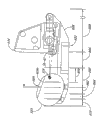
Fig. 1 and 2 illustrates the bottom of a vehicle 10, and it has a bottom 12, vertical base section 16 and the base plate 18 in an outside 14.One retractable vehicle step 20 is shown as with vehicle 10 and is connected.Particularly with reference to Fig. 2, retractable vehicle step 20 has a step part 22, it comprises the step platform 24 with an external side end 24a and a medial extremity 24b, the supporting bracket 26a, the 26b that form, and the driving arm 28a, the 28b that are positioned at supporting bracket 26a, 26b inboard.At the place, end of supporting bracket 26a, the 26b relative with step platform 24, supporting bracket 26a, 26b are pivotably connected to supporting arm 30a, 30b by rod pin 32a, 32b.Similarly, at the place, end of each supporting arm relative with supporting bracket 26a, 26b, supporting arm 30a, 30b are pivotably connected to anchor support 34a, 34b by rod pin 36a, 36b.Anchor support 34a, 34b are by welding, bolted connection, riveted joint, or other technology that technical personnel is known in the present technique field, are connected to rigidly on the bottom 12.
At the place, end of driving arm 28a, the 28b relative with step platform 24, driving arm 28a, the 28b of step part 22 are pivotably connected to actuating arm 38 by rod pin 40a, 40b.As Fig. 2 clearly shown in, actuating arm 38 preferably has a H shape structure, and at place, the end of the actuating arm 38 relative with driving arm 28a, 28b, is pivotably connected to anchor support 42a, 42b by rod pin 44a, 44b.Anchor support 42a, 42b are by welding, bolted connection, riveted joint, or other technology that technical personnel is known in the present technique field, are connected to rigidly on the bottom 12.
Therefore, as Fig. 2 clearly shown in, retractable vehicle step 20 limits following all pivots center: a first axle A-A, supporting arm 30a, 30b with respect to bottom 12 and/or anchor support 34a, 34b around this rotational; One second axis B-B, actuating arm 38 with respect to bottom 12 and/or anchor support 42a, 42b around this rotational; One third axle line C-C, supporting arm 30a, 30b and supporting bracket 26a, 26b rotate each other with respect to this axis; And a four axistyle D-D, actuating arm 38 and driving arm 28a, 28b rotate each other with respect to this axis.Fig. 1 as the lateral plan of Fig. 2 illustrates all axis A-A, B-B, C-C, D-D (being shown as a little).First axle A-A and third axle line C-C separate one first distance X, and the second axis B-B and four axistyle D-D separate a second distance Y.(in other words, first axle A-A and supporting arm 30a, 30b are to interval, the place of being rotationally connected first distance X of step part 22, and interval, the place of being rotationally connected of the second axis B-B and 38 pairs of step parts 22 of actuating arm second distance Y.) in one embodiment, first and second distance X, Y are unequal; In another embodiment, first distance X is greater than second distance Y.In one embodiment, first axle A-A is positioned at making progress of the second axis B-B.
The orientation of the first pivot center A-A is roughly parallel to the lower edge 19 of ground and/or vertical base section 16, and the orientation of the second pivot center B-B also is roughly parallel to ground and/or lower edge 19.(it should be understood that employed " being parallel to ground " be meant that being roughly parallel to regracting step vehicle mounted thereto lays the plane here, this is laid planar interception two-wheel contact patch on the side of vehicle of described regracting step is installed.) orientation of third axle line C-C and four axistyle D-D is arranged essentially parallel to the first axle A-A and the second axis B-B.
With further reference to Fig. 1, the first axle A-A and the second axis B-B separate one the 3rd apart from M, and third axle line C-C and four axistyle D-D separate one the 4th apart from N.In one embodiment, third and fourth is unequal apart from M, N; In another embodiment, the 3rd apart from M greater than the 4th apart from N.In one embodiment, when regracting vehicle step 20 is positioned at withdrawal and/or during expanded position, a straight line that connects first axle A-A and third axle line C-C is not parallel to a straight line that is connected the second axis B-B and four axistyle D-D.In one embodiment, when regracting vehicle step 20 is positioned at expanded position, connect the straight line of first axle A-A and third axle line C-C, the straight line than connecting the second axis B-B and four axistyle D-D becomes a less angle with respect to vertical direction.
In one embodiment, as shown in Figure 1, first aspect ratio is defined as ratio between can be below: the distance between (1) the first axle A-A and the second axis B-B, and (2) arm 30a of being limited by the distance between first axle A-A and the third axle line C-C, the length of 30b.In embodiment as shown in Figure 1, first aspect ratio is about 0.76.Similarly, second aspect ratio is defined as ratio between can be below: the distance between (1) the first axle A-A and the second axis B-B, and the length of (2) actuating arm 38 of being limited by the distance between the second axis B-B and the four axistyle D-D.In embodiment as shown in Figure 1, second aspect ratio is about 0.91.The 3rd aspect ratio is defined as ratio between can be below: the distance between (1) the first axle A-A and the second axis B-B, and the distance between (2) third axle line C-C and the four axistyle D-D.In embodiment as shown in Figure 1, the 3rd aspect ratio is about 1.32.
Referring now to Fig. 1, a motor 46 is installed to the bottom 12 on the mounting bracket (not shown) of contiguous regracting vehicle step 20 rigidly.Motor 46 is around a rotational miniature gears 48 that is roughly parallel to the plane that is limited by bottom 12.Driving gear 50 engagements on miniature gears 48 and the end that is formed on actuating arm 38.The actuating of motor 46 causes miniature gears 48 to rotate around rod pin 44a, and makes actuating arm 38 with respect to motor 46 and miniature gears 48 backward rotation.When actuating arm 38 rotates, by means of its with driving arm 28a, 28b be connected its promotion step part 22.Therefore, when causing motor 46 to rotate, motor 46 is mobile regracting vehicle step 20 between a position A who withdraws and a position B who extends, position A in withdrawal, the step platform roughly is positioned at from the outside of vehicle inside ideally, or is positioned on the fixing tread plate, and the position B that is extending, the step platform extends fully, provides a step with the forefoot portion at least to user's pin.When regracting vehicle step 20 under the effect of motor 46 power between the position A of withdrawal and the position B of extension when mobile, supporting arm 30a, 30b rotate with respect to rod pin 36a, 36b and 32a, 32b, and the motion of supporting and guiding regracting vehicle step 20.When block piece 52 that supporting arm 30a, 30b contact one preferably is installed on the vertical base section 16, reach the position B of extension.In one embodiment (as Fig. 1 clearly shown in), when being positioned at retracted position A, step platform 24 is inclined upwardly, and external side end 24a is positioned at from medial extremity 24b upwards.
When regracting vehicle step 20 was positioned at the position B of extension, one was applied to the downward power on the step platform 24, causes supporting arm 30a, 30b to be resisted against on the block piece 52.This structure causes the load on the step platform 24, mainly by supporting bracket 26a, 26b, and supporting arm 30a, 30b, and block piece 52 is born.At the position B that extends, the geometric form that regracting vehicle step 20 is taked makes supporting bracket 26a, 26b, and supporting arm 30a, 30b are in the loading of extended state.Rod pin 32a, 32b limit the pivotal axis of step part 22.The moment of torsion that is applied to the load generation on the step platform 24 is activated the antagonism of arm 38, and therefore, actuating arm 38 is subjected to the loading of axial compression between rod pin 40a, 40b and 44a, 44b.Because rod pin 44a, 44b are fixed in anchor support 42a, the 42b, so motor 46 is isolated with the load that is applied on the step platform 24.
This aspect of regracting vehicle step 20 prevents to damage motor by eliminating " oppositely loading ", even because very little load is when being carried on the step platform 24, also not around the reaction torque of the end of actuating arm 38.Therefore, motor 46 does not need to support the too load on 24 of step applying a reactive torque on the actuating arm 38.This feature is also removed the needs to dumb and unreliable power-transfer clutch, or any other the needs of device to motor 46 is thrown off from regracting vehicle step 20, or when extended position to the needs of regracting block piece of being used for engaging and support vehicle step 20 etc.
When at extended position B, as long as actuating arm 38 (as shown in Figure 1) rotation in the counterclockwise direction more deviates from vertical direction than supporting arm 30a, 30b, then regracting vehicle step 20 can play a role by this way.That is, when actuating arm 38 is parallel to, or the clockwise direction displacement surpasses when being parallel to supporting arm 30a, 30b, and actuating arm 38 will not keep supporting arm 30a, 30b against block piece 52.On the contrary, regracting vehicle step 20 will be tending towards moving towards retracted position A, and actuating arm 38 will be tending towards rotating around rod pin 44a, 44b anticlockwise direction (Fig. 1).In this case, motor 46 will need actuating arm 38 is applied a reactive torque, regracting vehicle step 20 is remained on the position B of extension.As mentioned above, do not wish to require motor 46 to play a role by this way.
Advantageously, be positioned at from step platform 24 backward and the join domain 31 that makes progress, some or all arm 30a, 30b, 38 are connected to step part 22.This structure farthest reduces the length of arm 30a, 30b and 38 and and stroke forward downwards, simultaneously, is convenient to whole " reaching " of the length of vehicle step 20, when step is positioned at extended position, is convenient to the placement of step platform 24.In addition, this structure allows to use (words of requirement) bevelled step part 22 (see figure 1)s, and it can be close to bottom 12 withdrawals, and makes the ground Clearance loss minimum.
In one embodiment, when from side observation step 20, in the plane perpendicular to the first axle (see figure 1), third and fourth axis is included in all points in the join domain 31, and a straight line that extends through all points forms the angle α with respect to about 10 degree of the upper surface of step platform 24.In another embodiment, angle α can be between about 5 to 20 degree.In the embodiment that also has other, four axistyle can be positioned at behind the join domain 31 third axle alignments and make progress Anywhere, and therefore angle α can be greater than any angle of 0 degree less than 90 degree.
One cover of dust or cap 54 can be installed on the lower body plate 18, step part 22 is provided the position of a storage, and prevent that dust or dust and dirt from accumulating on the step platform 24.
Because these features, regracting vehicle step 20 provides an auxiliary step that is used for vehicle user's practicality, and it can move into an extended position apace for use, and withdraws where necessary and hide.As above at length described, this functional mechanical complexity and high-caliber reliability with minimum.In addition, regracting vehicle step 20 easily is connected to the existing system of vehicle, so that it reaches bigger availability.For example, motor 46 can be connected to the electric system of vehicle, causes regracting vehicle step 20 to move to the position of extension apace, after closing vehicle motor, vehicle is parked in the place of parking, opens door, use remote control equipment (RCE) to signal to door-locking system such as a key case controller.Similarly, can send signals to motor 46 with the withdrawal vehicle step, fire an engine is put vehicle in startup, closes or locking is relevant with step etc.
Another embodiment of regracting vehicle step 120 is shown among Fig. 3-5.Regracting step 120 comprises a step part 122, and it comprises a supporting part or step platform 124, and its bolt together or other method are connected to an extendible portion or supporting bracket 126 rigidly.Step platform 124 has an external side end 124a and a medial extremity 124b, and forms step surface 124c on.Preceding and back supporting arm 130a, 130b are pivotally connected to supporting bracket 126 by pin 132a, 132b.One rigid frame 134 can be configured to be connected to the bottom 12 of vehicle necessarily, and it provides a failure-free to install to supporting arm 130a, the 130b that is installed in rotation on by pin 136a, 136b on the framework 134.Yet, should be realized that, can use any suitable structure or technology (outside the framework 134) that arm 130a, 130b are pivotally connected to vehicle.
Embodiment shown in Fig. 1-2 is shown in regracting vehicle step 120 among Fig. 3-5 and limits following all pivots center (among Fig. 4 clearly shown in): a first axle A-A, preceding supporting arm 130a with respect to bottom 12 and/or framework 134 around this rotational; One second axis B-B, back supporting arm 130b with respect to bottom 12 and/or framework 134 around this rotational; One third axle line C-C, preceding supporting arm 130a and supporting bracket 126 rotate each other with respect to this axis; And a four axistyle D-D, back supporting arm 130b and supporting bracket 126 rotate each other with respect to this axis.Fig. 3 as the lateral plan of Fig. 4 illustrates all axis A-A, B-B, C-C, D-D (being shown as a little).First axle A-A and third axle line C-C separate one first distance X, and the second axis B-B and four axistyle D-D separate a second distance Y.(in other words, first axle A-A and preceding supporting arm 130a are to interval, the place of being rotationally connected first distance X of step part 122, and the second axis B-B and the be rotationally connected place interval second distance Y of back supporting arm 130b to step part 122.) in one embodiment, first and second distance X, Y are unequal; In another embodiment, first distance X is greater than second distance Y.In one embodiment, first axle A-A is positioned at making progress of the second axis B-B.
The orientation of the first pivot center A-A is roughly parallel to ground and/or lower edge 19 (see figure 5)s, and the orientation of the second pivot center B-B also is roughly parallel to ground and/or lower edge 19.The orientation of third axle line C-C and four axistyle D-D is arranged essentially parallel to the first axle A-A and the second axis B-B.
With further reference to Fig. 3, the first axle A-A and the second axis B-B separate one the 3rd apart from M, and third axle line C-C and four axistyle D-D separate one the 4th apart from N.In one embodiment, third and fourth is unequal apart from M, N; In another embodiment, the 3rd apart from M greater than the 4th apart from N.In one embodiment, when regracting vehicle step 120 is positioned at withdrawal and/or during expanded position, a straight line that connects first axle A-A and third axle line C-C is not parallel to a straight line that is connected the second axis B-B and four axistyle D-D.In one embodiment, when regracting vehicle step 120 is positioned at expanded position, connect the straight line of first axle A-A and third axle line C-C, the straight line than connecting the second axis B-B and four axistyle D-D becomes a less angle with respect to vertical direction.
In one embodiment, as shown in Figure 3, first aspect ratio is defined as ratio between can be below: the distance between (1) the first axle A-A and the second axis B-B, and the length of (2) forearm 130a of being limited by the distance between first axle A-A and the third axle line C-C.In embodiment as shown in Figure 3, first aspect ratio is about 0.75.Similarly, second aspect ratio is defined as ratio between can be below: the distance between (1) the first axle A-A and the second axis B-B, and the length of (2) postbrachium 130b of being limited by the distance between the second axis B-B and the four axistyle D-D.In embodiment as shown in Figure 3, second aspect ratio is about 0.93.The 3rd aspect ratio is defined as ratio between can be below: the distance between (1) the first axle A-A and the second axis B-B, and the distance between (2) third axle line C-C and the four axistyle D-D.In embodiment as shown in Figure 3, the 3rd aspect ratio is about 1.35.
Referring now to Fig. 4, each supporting arm 130 comprises the parts of the one of a general plane, and it forms two coaxial supporting members 131 at its two ends.Coaxial supporting member can comprise coaxial hole, and the pin in their engage frame and the step part is so that be pivotally connected to each end with supporting arm.In other embodiments, coaxial supporting member can comprise the shaft portion of coaxial line, and they engage the hole that is formed in framework/step part, so that rotating connection to be provided.Perhaps, one or two supporting arm can form a mono-supporting member in its one or both ends, comprises the part width hole at a mono-full duration hole or a mono-center.
The spacing of coaxial supporting member 131 limits one in the each end of each supporting arm and connects width C W.Connect width and represent distance between supporting member and the opposite end that framework/the step part engages.For example, in Fig. 4, supporting arm 130a is pivotally connected to framework along connecting width on one, on connect distance between the outward flange that width equals coaxial supporting member 131.Supporting arm 130a is connected to the step part along connecting width once.Supporting arm 130b similarly limits and connects width on one and be connected width once.These four connection width that are shown among Fig. 4 are approximately equal, but their relative size can change on demand.
Supporting arm 130a, 130b also comprise a crosspiece 133 that interconnects supporting member 131 rigidly.Crosspiece advantageously has enough intensity, prevents that supporting arm 130a, 130b from from its planar structure roughly deflection taking place when riding on step platform 124 the user.Crosspiece can be taked any suitable structure, for example, and graphic full-scale, or a series of other transverse bars, on even keel extends, or the diagonal line extension of " X " shape ground etc.The high rigidity of the single-piece of crosspiece and arm 130a, 130b advantageously makes the width of arm minimize, yet, simultaneously, when extended position, provide stable supporting to step platform 124.
Before and the back supporting arm can take other form and structure, but be to comprise that respectively one is connected to the attaching parts of the general plane of framework with the step part ideally.One " attaching parts of general plane " can advantageously comprise parts that cause the one on plane, and as shown in Figure 4 supporting arm 130a or supporting arm 130b are such." attaching parts of general plane " of another variation comprises the two or more independent arm (being used for replacing the arm of mono-one) of interconnect frame and step part, by means of with arm and the framework relevant public last pivot center that is rotationally connected, and with arm and the step part relative relevant public following pivot center that is rotationally connected with framework, all arms are realized coplane.As the arm of one, the plane attaching parts of a multi-arm limits one at place, its end and connects width, and it extends between all outward flanges of the coaxial supporting member that the outer arm that constitutes attaching parts forms.
Continuation is with reference to Fig. 3 and 4, and supporting bracket 126 can comprise any suitable framing member, and it has enough rigidity and resists bending around level and longitudinal axis.Therefore, box type construction as shown in Figure 4 is suitable especially, can adopt other the shape known to them but those skilled in the art will recognize that support 126.The quite little connection width of arm 130 also can make support 126 make minimum width.By making the support 126 of sufficient length, step platform 124 can be positioned properly in case when step 120 is positioned at the position (see figure 3) of expansion convenient the use, and the length of arm 130 can keep minimum.
As Fig. 3 clearly shown in, supporting bracket 126 preferably forms an angle with step platform 124, therefore, from the height (when being positioned at the position of extension) on the surface haply of step platform 124 upwards and extend back.Therefore, preferred incline structure can further be reduced to the length of supporting arm 130 minimum.Therefore, step part 122 can be described as between the orientation that rotates that is directed to an expanded position (Fig. 3) of upwards rotating of a retracted position (Fig. 5) and moves.In other words, when moving to expanded position, step part 122 rotated around itself and being connected of supporting arm 130b, and when moving to retracted position, step part 122 upwards rotates around same connection.When being positioned at retracted position, step platform 124 is inclined upwardly (external side end 124a is positioned at from medial extremity 124b upwards), farthest reduces total downwards give prominence to of regracting step from the vehicle bottom.It is desirable to, should inclination upwards be 10 ° at least, and preferably be 20 ° at least.So that any water or foul are arranged from step, thus, in use improve its safety.
Because step part 122 is connected to framework 134 movably by supporting arm 130a, 130b, so shown in Fig. 5 and 3, it can move between retracted position A and extended position B respectively.Aforesaid embodiment, when the position B that extends, the regracting vehicle step 120 couples of vehicle operation persons provide a crash-resistant step.When a load was applied on the step platform 124 as mode shown in Figure 1, the geometric form of step part 122, supporting arm 130 and framework 134 caused arm 130a to load under extended state, and arm 130b loads under compressive state.Therefore, when a user rode on step platform 124, by step platform 124 being applied the antagonistic force of a level, arm 130b pushing-pressing arm 130a was against block piece 152.Block piece 152 prevents that the motion of actuating arm 138 from surpassing a selected position, like this, when actuating arm 138 is run into block piece 152, step 120 is in such structure: after step platform 124 is applied a load, it is tending towards further moving apart retracted position, but it is prevented from doing like this by means of block piece.Owing to concentrated these factors, so when the user was foot-operated, extendible step 120 firmly kept the position of its expansion, and does not need from motor 146 imput powers (will further go through hereinafter).These characteristics are eliminated the needs to independent lockout mechanism, usually in use, can see that lockout mechanism is the form of a hydraulic locking, the step platform is remained on the position of expansion.Therefore,, do not operate or throw off lockout mechanism,, thus, eliminate the unfavorable aspect of the regracting step system of prior art so these characteristics improve the comfort feature that regracting step is used owing to require the user in withdrawal or when launching step.
137 pairs of steps 120 of one drive system provide dynamic moving between withdrawal and extended position.Drive system 137 comprises that one is connected to the actuating arm 138 on the spinner 139, and both are installed in rotation on the pin 136a, and a motor 146 is connected to actuating arm 138 drivingly by spinner 139.Actuating arm 138 is connected to spinner 139, so that rotate in concert with it around pin 136a.In another embodiment, the unit that forms as one of spinner and actuating arm.
Motor 146 can be installed in framework 134, vehicle bottom, or any other suitable position.Motor 146 driven in rotation devices, actuating arm, step part etc., the mode of driving for example can be passed through a worm and gear 147, and its meshes the tooth (not shown) on the circumference that is formed on spinner 139.In another embodiment, motor can comprise the actuator of a linearity, and it pushes away on the circumference of spinner 139 or draws, with rotatable along both direction.Certainly, also can use any suitable device that connects motor and spinner/actuating arm.Advantageously, can use a window motor to come actuating device.Preferably, motor will be adjusted variation of temperature.
Drive system 137, or be used for any drive system of all embodiment of any regracting step that this paper discloses, can advantageously comprise such system: in range of movement in step, or in the scope of the moving-member of step, when running into an obstacle, this system stops the motion of step part, arm etc.When such system carefully is not inserted into his or her hand, arm etc. in the mechanism the people, the risk that can reduce to crush, also it near or when striking hard thing such as the roadside, can reduce to damage the step part of regracting step or the possibility of other parts.Also can imagine the anti-pinch/crash-proof system that uses as standard known in the art.
Advantageously, one or two arm 130a, 130b are connected to the step part 122 in join domain 135 (see figure 3)s, and it is positioned at the back of step platform 124 and makes progress.This structure with the length of arm 130a, 130b and downwards and stroke forward reduce to minimum, simultaneously, being convenient to step 120 has long overall " reaching ", when step is positioned at extended position, is convenient to place easily step platform 124.In addition, this structure allows to use (words that need) bevelled step part 122, and it can be withdrawn and be resisted against on the bottom 12, and the loss of ground Clearance is reduced to minimum.
In one embodiment, when observing step 120 from the side, (see figure 3) in perpendicular to the plane of first axle, third and fourth axis are included in all points in the join domain 135, and a straight line that extends through all points forms the angle of about 10 degree with respect to the upper surface of step platform 124.In another embodiment, this angle can be to spend between 20 degree 5.In also having other embodiment, four axistyle can be positioned at join domain 135 Anywhere, be positioned at the third axle line backward and upwards, therefore, angle β can be greater than 0 degree with less than 90 any angles of spending.
One cover of dust or cap 154 can be installed on the lower body plate 18, store the position step part 122 is provided one, and prevent that dust or dirt from accumulating on the step platform 124.Cover of dust 154 advantageously has one from the outstanding downwards part of vehicle lower surface, and it traverses the gap that is formed between step platform 124 upper surfaces and the contiguous vehicle structure and extends, and extensible or walk around the outward flange of step platform 124.Therefore, around the outward flange and the upper surface of step platform 124, cover of dust 154 forms a protective cover.Have found that, cover of dust 154 reduces water, dust, mud and/or the accumulation of fragment on the step platform, in safety and aestheticly provide significant benefit, simultaneously, when he or she rides on the step platform or stands near it, reduce to stain the possibility of user's clothes.
Therefore, the regracting vehicle step utilizes a quite compact attaching parts system to support step platform 124 when being in expanded position.Quite short, compact supporting arm 130 can be made into minimum width, as framework 134 and supporting bracket 126.Step platform 124 can make thus roughly is wider than framework/supporting arm/supporting bracket.In other words, step platform 124 preferably roughly is wider than any connection width that is formed by supporting arm.Advantageously, the width of step platform is about framework, supporting arm, supporting bracket, or the 2-8 of any connection width that is formed by supporting arm doubly.Therefore, the regracting step provides a wide step platform to the vehicle user, simultaneously the width of framework, attaching parts system etc. and the requirement in space is reduced to minimum.
Wide step platform 124 and relative narrow framework/supporting arm/supporting bracket, allow the easily auxiliary step of a mono-regracting step, and do not occupy the big space of the lower vehicle of connecting frame, supporting arm and supporting bracket as two adjacent doors of a vehicle.Fig. 6 A illustrates a vehicle 200, and the one side has a Qianmen 202 and an adjacent back door 204.In Fig. 6 A, as seen the regracting vehicle step does not have a part, because it is in the position of withdrawal.Fig. 6 B illustrates the regracting vehicle step and moves to expanded position (after opening Qianmen 202, or in response to aforesaid other action) step platform 124 afterwards.Easily as seen, the auxiliary step of step platform 124 for providing convenience by the people who appoints Yishanmen 202,204 to enter vehicle.Extend to about 1/4 the place of locating previously of each gate-width degree at step platform 124, the width of step platform will enough be wider than user's pin, so that a step easy to use to be provided.Extend 1/2 width that the step platform covers Yue Gemen, an additional safety factor above 1/4 width step platform can be provided.The one step platform that traverses the overall with extension of two doors basically is the most favourable, and its favourable part is that when user's step was on the step platform, the user need not to look down step basically, concerning the people who carries large numbers of items, is convenient to its convenient use.
From broadly, the width that the novel structure of regracting vehicle step allows to be independent of framework, arm and/or supporting bracket is selected the width of step platform.Therefore, be intended to need not extend the overall with of door as the step platform of the step of two adjacent doors.It can replace only about 4-5 foot wide (compare with the tread plate of standard fixed, it is wide that it is generally the 6-8 foot), and a step easily is provided, and simultaneously, whole device size and weight is remained on minimum.Have found that this special width is in the use of providing convenience (by a quite wide step platform) and avoid providing between excessive, the huge device balance an of the best.Similarly, the step platform that is intended to be used for the regracting step of single car door can be reduced to best step platform width, and it is less than the overall with of door.
Fig. 7-11 illustrates another embodiment 220 of the regracting vehicle step that is attached to vehicle bottom 12, and vehicle has doorframe, a base plate 18 that is suitable for admitting a vehicle doorn (not shown), and the outside plate of a perpendicular or surface 52.Retractible step 220 comprises a step part 222, and it comprises that a usefulness bolt or other method are connected to the step platform 224 on the supporting bracket 226 rigidly.Preceding and back supporting arm 230a, 230b are pivotally connected to supporting bracket 226 by pin 232a, 232b.Back supporting arm comprises that a withdrawal block piece 231a and launches block piece 231b.One is configured to be connected to vehicle bottom 12 necessary rigid frames 234, provides a fixing installation to supporting arm 230a, 230b, and they are installed in rotation on the framework 234 by pin 236a, 236b.Framework 234 can comprise the extension 235 of a front portion, and it forms a horizontal stripe 235a, so that by bolted connection, riveted joint, welding, or other orthodox method is attached to vehicle bottom 12 with framework 234.Yet, should be realized that, can use various structures to substitute extension 235 and horizontal stripe 235a, or add extension 235 and horizontal stripe 235a to, so that framework 234 is attached to the vehicle of variety classes and model.Similarly, should be realized that, can use any suitable structure or technology (outside the framework 234) that arm 230a, 230b are connected on the vehicle.
Preceding supporting arm 230a rotates around one first pivot center A-A, first axle is arranged essentially parallel to the edge bottom or extension 300 orientations of vehicle bottom 12, then supporting arm 230b rotates around one second pivot center B-B, and second axis also is parallel to edge 300 orientations bottom basically.Forearm 230a and supporting bracket 226 rotate each other with respect to the 3rd pivot center C-C, and postbrachium 230b and supporting bracket 226 rotate each other with respect to the 4th pivot center D-D.Third axle line C-C and four axistyle D-D are roughly parallel to first and second axis orientation.
For clarity, each axis A-A does not add in Fig. 7 and 8 to the distance between the D-D and marks; Yet, because it relates to the above embodiments really, so the discussion to the geometric form of axis arranged will be applicable to the embodiment of Fig. 7-9 with same effectiveness below.With reference to Fig. 7, first axle A-A and third axle line C-C separate one first distance, and the second axis B-B and four axistyle D-D separate a second distance.Among one embodiment, first and second distances are unequal; In another embodiment, first distance is greater than second distance.In one embodiment, first axle A-A is positioned at making progress of the second axis B-B.
The first axle A-A and the second axis B-B separate one the 3rd distance, and third axle line C-C and four axistyle D-D separate one the 4th distance.Among one embodiment, third and fourth distance is unequal; In another embodiment, the 3rd distance is greater than second distance.In one embodiment, when regracting vehicle step 220 is positioned at withdrawal and/or during expanded position, a straight line that connects first axle A-A and third axle line C-C is not parallel to a straight line that is connected the second axis B-B and four axistyle D-D.In one embodiment, when regracting vehicle step 220 is positioned at expanded position, connect the straight line of first axle A-A and third axle line C-C, the straight line than connecting the second axis B-B and four axistyle D-D becomes a less angle with respect to vertical direction.
In one embodiment, as shown in Figure 7, first aspect ratio is defined as ratio between can be below: the distance between (1) first axle and second axis, and the length of (2) forearm 230a of being limited by the distance between first axle A-A and the third axle line C-C.In embodiment as shown in Figure 7, first aspect ratio is about 0.21.Similarly, second aspect ratio is defined as ratio between can be below: the distance between (1) first axle and second axis, and the length of (2) postbrachium 230b of being limited by the distance between second axis and the four axistyle.In embodiment as shown in Figure 7, second aspect ratio is about 0.22.The 3rd aspect ratio is defined as ratio between can be below: the distance between (1) first axle and second axis, and the distance between (2) third axle line C-C and the four axistyle D-D.In embodiment as shown in Figure 7, the 3rd aspect ratio is about 1.00.
As shown in Fig. 7 and 8, retractible step 220 is moved between retracted position A and extended position B.When step 220 was positioned at the position B of extension, the power that is applied to downwards on the step platform 24 caused the block piece 231b of expansion to be resisted against on the preceding supporting arm 230a.At this moment, step 220 is in such structure: after step platform 224 was applied a load, it was tending towards further moving apart retracted position B, but it is prevented from doing like this by means of launching block piece 231b.Owing to concentrated these factors, so when the user was foot-operated, extendible step 220 firmly kept the position of its expansion, and does not need from motor 246 imput powers (will further go through hereinafter).These characteristics are eliminated the needs to independent lockout mechanism, usually in use, can see that lockout mechanism is the form of a hydraulic locking, the step platform is remained on the position of expansion.Therefore,, do not operate or throw off lockout mechanism,, thus, eliminate the unfavorable aspect of the regracting step system of prior art so these characteristics improve the comfort feature that regracting step is used owing to require the user in withdrawal or when launching step.
Advantageously, one or two arm 230a, 230b are connected to and are positioned at from step platform 224 backward and the step part 222 of join domain 231 (see figure 7)s that make progress.This structure farthest reduces the length of arm 230a, 230b and and stroke forward downwards, simultaneously, is convenient to whole " reaching " of the length of vehicle step 20, when step is positioned at extended position, is convenient to the placement of step platform 224.In addition, this structure allows to use (words of requirement) bevelled step part 222, and it can be close to bottom 12 withdrawals, and/or it is folding to be close to arm 230a, 230b, the time realize packing compactly in withdrawal, it is convenient to step 220 again and installs in the little space of bottom 12 and make the ground Clearance loss minimum.
Therefore, regracting step 220 shown in Fig. 7-9 has a motion on a large scale, making whole step platforms 224 be positioned at the outside of first axle A-A when the step part is positioned at expanded position B, and at least a portion of step platform 224 is positioned at the inboard of the second axis B-B when the step part is positioned at retracted position A.In one embodiment, when step part 222 was positioned at expanded position, the upper surface of step platform 224 was topmost portion of the regracting step 220 in supporting bracket 226 outsides.In another embodiment, when step part 222 is positioned at expanded position, the about 10-12 inch in the upper surface side of resting on the ground of step platform 224.In another embodiment, when step part 222 is positioned at expanded position, about 10 inches of the upper surface side of resting on the ground of step platform 224.In another embodiment, when step part 222 is positioned at expanded position, about 11 inches of the upper surface side of resting on the ground of step platform 224.In another embodiment, when step part 222 is positioned at expanded position, about 12 inches of the upper surface side of resting on the ground of step platform 224.
In one embodiment, when observing step 220 from the side, in the plane perpendicular to the first axle (see figure 7), third and fourth axis is included in all points in the join domain 231, and a straight line that extends through all points forms the angle γ with respect to about 50 degree of the upper surface of step platform 224.In other embodiments, angle γ can for about 20 and 80 the degree between, or 40 and 60 the degree between.In the embodiment that also has other, four axistyle can be positioned at behind the join domain 231 third axle alignments and make progress Anywhere, and therefore angle γ can be greater than any angle of 0 degree less than 90 degree.
In the embodiment shown in Fig. 7 and 8, the upper surface of step platform 224 can form a substantially horizontal plane on that extend and position withdrawal.
Supporting arm 230a preferably had an arc structure before Fig. 7,8 and 9 illustrated, and made straight relatively centre portion between two inclined end portion.This preferable geometric form guarantee to withdraw with block piece 231a, the 231b supporting arm 230a before a certain position contacts that launches, described position is its position for the interval that is rotationally connected of pin 232a, 236a.Have found that, the shearing load of the arm 230a of contiguous these point of connection, for example, and contingent the sort of shearing load when the expanded position of without hindrance block piece 231b, this load can lead to the failure under certain situation.
In the embodiment that is in discussion at present, when retractible step 220 was in the position of withdrawal, it is hidden invisible in adult's sight line of generally standing in car bypass limit, and was preferably invisible fully.In this position, step part 222, and the remainder of framework 234 and regracting step 220 is arranged on the lower extension or the lower edge back of vehicle bottom 12.Preferably, the about 1.5-4.5 inch in back of the bottom of the front edge of step platform 224 interval outside plate 52; More preferably, the back of the bottom of front edge interval outside plate 52 is at least about the 2.5-3.5 inch; Best is that the back of the bottom of front edge interval outside plate 52 is at least about 3.2 inches.In addition, step part 222 under extension point 222a be positioned at the top of the lower extension 300 of bottom 12, or below extension 300 enough back of extension 300 (and/or be arranged on) outstanding such quantity, it is kept basically, and preferably fully remain on outside the adult visual field that car generally stands outward.In one embodiment, regracting step 220 is invisible in the one-tenth human eye of standing from 5 feet on vehicle; In another embodiment, regracting step 220 is invisible in the one-tenth human eye of standing from 10 feet on vehicle; In another embodiment, regracting step 220 is invisible in the one-tenth human eye of standing from 20 feet on vehicle.
This disguise is mainly by providing moving on a large scale of step part 222 to be achieved.Before and back supporting arm 230a, 230b make long enough, and/or be provided with enough angular motion on a large scale, with before the step part 222 with the position A that afterwards moves into hidden withdrawal.Compare with step part 222, arm 230a, 230b also make long enough, and are installed on the framework 234 on the pivotal point of interval extension 300 enough back, the front edge of step platform 224 is moved to the back of extension 300 in the process of withdrawal.Select the point of connection of arm 230a, 230b and framework 234 and step part 222, prevent two arms on wide stroke range with the interference of other motion.Framework 234 comprises that enough gaps hold the motion that step part 222 and arm 230a, 230b entered and left retracted position A.Therefore, when step part 222 withdrawal, basically step 200 not part in general " roadside " viewer's eye as seen, and have the vehicle of step 200 installation and that withdraw, for such viewer, will seem that " storage " pattern with this vehicle is consistent basically.
Fig. 9 illustrates the preferred drive system 237 that step 220 is provided dynamic motion between withdrawal and extended position.This system 237 preferably comprises an actuating arm 238, and it is connected to back supporting arm 230b drivingly, and is also connected to a clutch pack or torque limiter 239.Clutch pack 239 and main gear system 240 and a motor 246 engagements.Perhaps, but motor 246 direct drive clutch pacies 239, and can omit main gear system 240.One sub-frame 248 can be set main gear system 240 and/or motor 246 be installed with respect to framework 234.Clutch pack 239 and actuating arm 238 preferably are installed in rotation on the framework 234, like this, the propulsive effort that acts on clutch pack 239 teeth causes clutch pack 239 and actuating arm 238 to rotate together, and step 220 is moved into or shifts out the position of withdrawal.
Figure 10 and 11 illustrates the preferred construction of clutch pack 239 and actuating arm 238 in more detail.Clutch pack 239 comprises hub 250 perforate or that key connects, and it is configured to be attached to rotationally on the framework 234.Actuating arm 238 comprises an opening that splines 252, in the time of on being installed to hub, provides with the actv. of hub 250 to be connected.Adjacent with actuating arm 238 is first clutch parts 254 that form by high friction clutch material (known in the art), one has the input gear 256 of conventional gears, it is used for accepting the propulsive effort that applied by main gear system 240 and/or motor 246, and second clutch part 258 that preferably is similar to first clutch part 254.One pad 260 that has keyway covers clutch parts 258, and an oblique spring 262 and nut 264 (with the hub screw-threaded engagement) are fixed to all components on the hub 250.Therefore, under spring and nut applied pressure, input gear 256 frictionally is coupled on actuating arm 238, hub 250 and the pad 260 by clutch part 254,258.
In normal running, input gear 256 and actuating arm 238 will rotate together around their common pivot axis line, just move as a single part, move between withdrawal and extended position in driving step 220 under the power of motor 246.Yet under suitable situation, clutch part 254,258 will allow to slide between input gear 256 and actuating arm 238, thereby between gear 256 and arm 238 relative angular motion take place.A kind of situation that this slip takes place is, step is positioned at extended position or during near extended position, then the vehicle user must manually be pushed into extended position with step with supply disconnecton when motor 246.Power-transfer clutch allows step withdrawal manually by this way, and need not reverse loading motor 246, avoids damaging with the protection motor.
Clutch pack 239 also is an actv. in the situation below: step 220 is moved under the power of motor, but strikes an obstacle, and it stops step further to be moved.In this case, owing to allow it to be rotated further under the power that applies, and step is motionless, avoids burning motor 246, so power-transfer clutch prevents to damage motor (with possible injury under the situation of the hand of meeting the people in step, leg etc.).If requirement, it also can use together in conjunction with the anti-pinch/anticollision system of aforesaid standard, so that further safety measure to be provided.
Figure 12 and 13 illustrates another embodiment 420 of regracting vehicle step, and wherein, two or more retraction assemblies 450 are connected on the mono-step platform 424, and the withdrawal and the expansion of single step platform 424 are provided.Each retraction assemblies 450 can comprise the structure that roughly is similar to any embodiment that is used for the regracting vehicle step that discloses herein; Yet the embodiment shown in Figure 12 and 13 adopts the mechanism that discloses among above Fig. 3-5.One or two assembly 450 can comprise a motor that is used for mobile step between expanded position (Figure 12) and retracted position (Figure 13).
Assembly 450 inwardly preferably is connected to step platform 424 in the position at interval at the outward flange with step platform 424.The load that this structural limitations applies on step platform 424 and and the point of connection of assembly 450 in any point between the maximum, force moment arm that defines, and when being connected to step on the vehicle, reduce the side direction " basal surface " that occupies by step 420.
Figure 14 and 15 illustrates another embodiment 520 of regracting vehicle step, and except discussed below, it can be similar to the above embodiments (the particularly embodiment as shown in Fig. 7-9).Be shown as the regracting step 520 that is attached on the vertical base part 16 and comprise a step part 522, it comprises that a bolt together or alternate manner are connected to the step platform 524 on the supporting bracket 526 rigidly.Preceding and back supporting arm 530a, 530b are pivotally connected to supporting bracket 526 by pin 532a, 532b.Each can be configured to be used for being connected to necessary parts on the vehicle base section 16 to one rigid frame 534 with being connected support 541, and they provide a fixing installation to supporting arm 530a, 530b, and they are installed in rotation on the framework 534 by pin 536a, 536b.By means of being connected with suitable the further of drive system (not shown), pin 536b also can be used as the axle drive shaft of back supporting arm 530b.Therefore, pin 536b can have than other pin 532a, 532b, diameter that 536a is big.In other embodiments, pin 536a can be used as axle drive shaft, therefore, can be pin 536a and selects a bigger diameter.
By bolted connection, riveted joint, welding, or other orthodox method, connect support 541 and can be fixed on the vertical base section 16 (with being fixed to the framework 534 that is connected support 541).Yet, should be realized that, can use various structures to substitute and connect support 541, or add connection support 541 to, so that framework 534 is attached to the vehicle of variety classes and model.Similarly, should be realized that, although shown in framework be preferred construction, can use any suitable structure or technology (outside the framework 534) that arm 530a, 530b are pivotally connected on the vehicle.
As the above embodiments, be shown in retractable vehicle step 520 among Figure 14-15 and form one group of axis A-A of first to fourth corresponding to above-mentioned group axis to D-D.For clarity, each axis A-A to the distance between the D-D does not mark in Figure 14-15; Yet the discussion to the geometric form of axis arranged will be applicable to the embodiment of Figure 14-15 with same effectiveness below.Because it relates to the above embodiments really.With reference to Figure 14, first axle A-A and third axle line C-C separate one first distance, and the second axis B-B and four axistyle D-D separate a second distance.Among one embodiment, first and second distances are unequal; In another embodiment, first distance is greater than second distance.In one embodiment, first axle A-A is positioned at making progress of the second axis B-B.
The first axle A-A and the second axis B-B separate one the 3rd distance, and third axle line C-C and four axistyle D-D separate one the 4th distance.Among one embodiment, third and fourth distance is unequal; In another embodiment, the 3rd distance is greater than second distance.In one embodiment, when regracting vehicle step 520 is positioned at withdrawal and/or during expanded position, a straight line that connects first axle A-A and third axle line C-C is not parallel to a straight line that is connected the second axis B-B and four axistyle D-D.In one embodiment, when regracting vehicle step 220 is positioned at expanded position, connect the straight line of first axle A-A and third axle line C-C, the straight line than connecting the second axis B-B and four axistyle D-D becomes a less angle with respect to vertical direction.
The rear surface of preceding supporting arm 530a diminishes forward at upper and lower transition position 543a, 543b, therefore, forms thin centre portion 545 between thicker end 549a, 549b.This structure allows arm 530a, 530b partly to be nested in " interior " each other at the extreme place of its range of movement, this increases the range of movement of step part 522 again, and the end that allows arm simultaneously becomes thicker, so that bear the application force that runs into better at they and framework and the step part place of being rotationally connected.Owing to give arm 530a, 530b and step part 522 with wider motion like this, so step part 522 can extend away from vehicle more when launching, and when withdrawal, can be withdrawn into more in the vehicle, to improve its disguise.
As shown in figure 14, back supporting arm 530b has a thicker top 551, and when regracting vehicle step 520 was positioned at retracted position A, top 551 was near to or in contact with the centre portion 545 of preceding supporting arm 530a.Therefore, preceding supporting arm 530a is shown as and rotates backward above certain a bit, if arm 530a has uniform thickness, then arm 530a originally can stop at this some place (by means of with the contacting of back supporting arm 530b).In general, turn at a point by supporting arm 530a before making, at this some place, the part of postbrachium 530b and straight line interval one vertical distance that is connected first axle A-A and third axle line C-C, it then can realize increasing the motion of scope backward less than half of the maximum ga(u)ge of forearm 530a.By making forearm 530a turn to certain a bit, thin centre portion 545 thus, can farthest increase the scope of motion at this some place contact postbrachium 530b.
Figure 15 illustrates when regracting vehicle step 520 is in the position B of extension, the nest relation of arm 530a, 530b.The thin bottom 553 of back supporting arm 530b is at close transition position 543b, near to or in contact with the centre portion 545 of preceding supporting arm 530a.Under principle discussed above, by the wideer proal scope of forearm 530a realization of thin centre portion 545 comparable uniform thickness.
Therefore, regracting vehicle step 520 shown in Figure 14-15 has a wide range of movement, like this, when the step part is positioned at expanded position B, whole step platforms 524 is positioned at the outside of first axle A-A, and when the step part was positioned at retracted position A, the step platform 524 of at least a portion was positioned at the inboard of the second axis B-B.
Figure 16-17 illustrates another embodiment 620 of regracting vehicle step, and except discussed below, it can be similar to the above embodiments.Be shown as the regracting step 620 that is attached on the bottom 12 and comprise a step part 622, it comprises that a bolt together or alternate manner are connected to the step platform 624 on the supporting bracket 626 rigidly.Preceding and back supporting arm 630a, 630b are pivotally connected to supporting bracket 626 by pin 632a, 632b.Each can be configured to be used for being connected to necessary parts on the bottom 12 to one rigid frame 634 with being connected support 641, and they provide a fixing installation to supporting arm 630a, 630b, and they are installed in rotation on the framework 634 by pin 636a, 636b.
By bolted connection, riveted joint, welding, or other orthodox method, framework 634 be connected support 641 and can be fixed on the vertical base section 16 (with being fixed to the framework 634 that is connected support 641).Yet, should be realized that, can use various structures to substitute and connect support 641, or add connection support 641 to, so that framework 634 is attached to the vehicle of variety classes and model.Should be realized that, although shown in the design be preferred construction, can use other suitable structure or technology (outside the framework 634) that arm 630a, 630b are pivotally connected on the vehicle.
As the above embodiments, be shown in retractable vehicle step 620 among Figure 16-17 and form one group of axis A-A of first to fourth corresponding to above-mentioned group axis to D-D.For clarity, each axis A-A to the distance between the D-D does not mark in Figure 16-17; Yet the discussion to the geometric form of axis arranged will be applicable to the embodiment of Figure 16-17 with same effectiveness below.Because it relates to the above embodiments really.With reference to Figure 16, first axle A-A and third axle line C-C separate one first distance, and the second axis B-B and four axistyle D-D separate a second distance.Among one embodiment, first and second distances are unequal; In another embodiment, first distance is greater than second distance.In one embodiment, first axle A-A is positioned at making progress of the second axis B-B.
The first axle A-A and the second axis B-B separate one the 3rd distance, and third axle line C-C and four axistyle D-D separate one the 4th distance.Among one embodiment, third and fourth distance is unequal; In another embodiment, the 3rd distance is greater than second distance.In one embodiment, when regracting vehicle step 620 is positioned at withdrawal and/or during expanded position, a straight line that connects first axle A-A and third axle line C-C is not parallel to a straight line that is connected the second axis B-B and four axistyle D-D.In one embodiment, when regracting vehicle step 620 is positioned at expanded position, connect the straight line of first axle A-A and third axle line C-C, the straight line than connecting the second axis B-B and four axistyle D-D becomes a less angle with respect to vertical direction.
The rear surface of preceding supporting arm 630a diminishes forward and form thin centre portion 645 between the 649a of thicker end portion, 649b.When regracting step 620 is positioned at expanded position B, this structure allows arm 630a, 630b partly to be nested in " interior " each other, this increases step part 622 range of movement forward again, and the end that allows arm simultaneously becomes thicker, so that bear the application force that runs into better at the place of being rotationally connected of they and framework and step part.Owing to give the motion of arm 630a, 630b and step part 622 like this, so step part 622 can extend away from vehicle more when launching with bigger scope forward.
As shown in figure 17, when regracting vehicle step 620 was positioned at expanded position B, the bottom of the rounding of back supporting arm 630b was near to or in contact with the thin centre portion 645 of preceding supporting arm 630a.Therefore, back supporting arm 630b is shown as forward to rotate and surpasses certain a bit, if forearm 630a has uniform thickness, then arm 630b originally can stop at this some place (by means of with the contacting of preceding supporting arm 630a).In general, by making back supporting arm 630b turn at a point, at this some place, the part of postbrachium 630b and straight line interval one vertical distance that is connected first axle A-A and third axle line C-C, it then can realize increasing the motion of scope forward less than half of the maximum ga(u)ge of forearm 630a.By making postbrachium 630b turn to certain forward a bit, thin centre portion 645 thus, can farthest increase the scope of motion at this some place contact postbrachium 630b.
In the narrow space shown in embodiment shown in Figure 16-17 is specially adapted to, they are between the vehicle doorn that makes progress 21 bottoms of adjacent vehicle frame unit 23.Because the space of withdrawal is very little backward, so step platform 624 mainly upwards rotates when withdrawal.Therefore, in an illustrated embodiment, when step part 622 was positioned at retracted position A, the front edge 624a of step platform 624 was positioned at first axle A-A top.In addition, when step part 622 was positioned at retracted position A, whole step platforms 624 can be positioned at the front of first axle A-A.
When withdrawal, retractable vehicle step 620 is hidden and invisible in the other viewer's who stands of vehicle sight line basically because the lower surface 624d of step platform 624 from the lower edge of door 21 with respect to vertically inwardly and downwards extending to the angle β that is about the 45-65 degree.The position of the step platform 624 of withdrawal " make progress " also stop arm, framework etc. not by general car in viewer's the sight line.By japanning or alternate manner the lower surface 624d of step platform is colored as dark color (black, Dark grey etc.), or it is colored as and couplings such as on every side bottom, framework, can further improve disguise.
Figure 18 and 19 illustrates another embodiment 720 of regracting vehicle step, and except discussed below, it can be similar to the above embodiments.Regracting step 720 comprises a step part 722, and it comprises that a bolt together or alternate manner are connected to the step platform 724 on the supporting bracket 726 rigidly.Preceding and back supporting arm 730a, 730b are pivotally connected to supporting bracket 726 by pin 732a, 732b.One rigid frame 734 can be configured to be used for being connected to necessary parts on the vehicle base section 16, and it provides a fixing installation to supporting arm 730a, 730b, and they are installed in rotation on the framework 734 by pin 736a, 736b.By means of being connected with suitable the further of drive system (not shown), pin 736b also can be used as the axle drive shaft of back supporting arm 730b.Therefore, pin 736b can have than other pin 732a, 732b, diameter that 736a is big.In other embodiments, pin 736a can be used as axle drive shaft, therefore, can be pin 736a and selects a bigger diameter.
By bolted connection, riveted joint, welding, or other orthodox method, framework 734 can be fixed on the vertical base section 16.Yet, should be realized that, can use various structures to substitute framework 734, or add framework 734 to, so that arm 730a, 730b are attached to vehicle, or the vehicle of variety classes and model.
As the above embodiments, be shown in retractable vehicle step 720 among Figure 18-19 and form one group of axis A-A of first to fourth corresponding to above-mentioned group axis to D-D.For clarity, each axis A-A to the distance between the D-D does not mark in Figure 18-19; Yet the discussion to the geometric form of axis arranged will be applicable to the embodiment of Figure 18-19 with same effectiveness below.Because it relates to the above embodiments really.With reference to Figure 18, first axle A-A and third axle line C-C separate one first distance, and the second axis B-B and four axistyle D-D separate a second distance.Among one embodiment, first and second distances are unequal; In another embodiment, first distance is greater than second distance.In one embodiment, first axle A-A is positioned at making progress of the second axis B-B.
The first axle A-A and the second axis B-B separate one the 3rd distance, and third axle line C-C and four axistyle D-D separate one the 4th distance.Among one embodiment, third and fourth distance is unequal; In another embodiment, the 3rd distance is greater than second distance.In one embodiment, when regracting vehicle step 720 is positioned at withdrawal and/or during expanded position, a straight line that connects first axle A-A and third axle line C-C is not parallel to a straight line that is connected the second axis B-B and four axistyle D-D.In one embodiment, when regracting vehicle step 720 is positioned at expanded position, connect the straight line of first axle A-A and third axle line C-C, the straight line than connecting the second axis B-B and four axistyle D-D becomes a less angle with respect to vertical direction.
The top of forearm 730a is crooked backward, and the bottom of postbrachium 730b so that arm and step part move on a large scale, simultaneously, allows arm to do relatively thickly and solid to front curve.Owing to give arm 730a, 730b and step part 722 with wider motion like this, so step part 722 can extend away from vehicle more when launching, and when withdrawal, can be withdrawn into more in the vehicle, to improve its disguise.In addition, it is considerably close each other to the position of C-C, D-D to A-A, B-B and lower axis that crooked arm allows to go up axis, need not to use inappropriate thin and weak arm.
In the narrow space shown in embodiment shown in Figure 18-19 is specially adapted to, it is between the bottom of the vertical lower that makes progress 16 of adjacent vehicle frame unit 23.Because the space of withdrawal is very little backward, so step platform 724 mainly upwards rotates when withdrawal.Therefore, in an illustrated embodiment, when step part 722 was positioned at retracted position A, the front edge 724a of step platform 724 was positioned at first axle A-A top.
When withdrawal, retractable vehicle step 720 is hidden and invisible in the other viewer's who stands of vehicle sight line basically because the lower surface 724d of step platform 724 from the lower edge of door 21 with respect to vertically inwardly and downwards extending to the angle ε that is about the 35-55 degree.Although unhidden up hill and dale as other embodiment, the position of the step platform 724 of withdrawal " make progress " also the signal portion of stop arm, framework etc. not by general car in viewer's the sight line.By japanning or alternate manner the lower surface 724d of step platform is colored as dark color (black, Dark grey etc.), or it is colored as and couplings such as on every side bottom, framework, can further improve disguise.
Figure 20 and 21 illustrates another embodiment 820 of regracting vehicle step, and except discussed below, it can be similar to the above embodiments.Regracting step 820 comprises a step part 822, and it comprises that a bolt together or alternate manner are connected to the step platform 824 on the supporting bracket 826 rigidly.Preceding and back supporting arm 830a, 830b are pivotally connected to supporting bracket 826 by pin 832a, 832b.One rigid frame 834 can be configured to be used for being connected to vertical base part 16 (or frame unit 23) and go up necessary parts, and it provides a fixing installation to supporting arm 830a, 830b, and they are installed in rotation on the framework 834 by pin 836a, 836b.
By bolted connection, riveted joint, welding, or other orthodox method, framework 834 can be fixed on the vertical base section 16 (or frame unit 23).Yet, should be realized that, can use various structures to substitute framework 834, or add framework 834 to, so that arm 830a, 830b are attached to vehicle, or the vehicle of variety classes and model.
As the above embodiments, be shown in retractable vehicle step 820 among Figure 20-21 and form one group of axis A-A of first to fourth corresponding to above-mentioned group axis to D-D.For clarity, each axis A-A to the distance between the D-D does not mark in Figure 20-21; Yet the discussion to the geometric form of axis arranged will be applicable to the embodiment of Figure 20-21 with same effectiveness below.Because it relates to the above embodiments really.With reference to Figure 20, first axle A-A and third axle line C-C separate one first distance, and the second axis B-B and four axistyle D-D separate a second distance.Among one embodiment, first and second distances are unequal; In another embodiment, first distance is greater than second distance.
The first axle A-A and the second axis B-B separate one the 3rd distance, and third axle line C-C and four axistyle D-D separate one the 4th distance.Among one embodiment, third and fourth distance is unequal; In another embodiment, the 3rd distance is greater than second distance.In one embodiment, when regracting vehicle step 820 is positioned at withdrawal and/or during expanded position, a straight line that connects first axle A-A and third axle line C-C is not parallel to a straight line that is connected the second axis B-B and four axistyle D-D.In one embodiment, when regracting vehicle step 820 is positioned at expanded position, connect the straight line of first axle A-A and third axle line C-C, the straight line than connecting the second axis B-B and four axistyle D-D becomes a less angle with respect to vertical direction.
Arm 830a, 830b are convenient to the motion of the extremely wide region of arm and step part, simultaneously, allow arm to do relatively thickly and solid.Owing to give arm 830a, 830b and step part 822 with wider motion like this, so step part 822 can extend away from vehicle more when launching, and when withdrawal, can be withdrawn into more in the vehicle, to improve its disguise.
In an illustrated embodiment, all arm 830a, 830b bend to such degree: when step part 822 is positioned at the position A of withdrawal, one straight line that connects first axle A-A and third axle line C-C will intersect with the part near the postbrachium 830b of the second axis B-B, and/or a straight line that connects the second axis B-B and four axistyle D-D will intersect with the part near the forearm 830a of third axle line C-C.Its result, when step part 822 was positioned at retracted position A, one or two among third axle line C-C and the four axistyle D-D was positioned at the top of first axle A-A.
Therefore, regracting vehicle step 820 shown in Figure 20-21 has a wide range of movement, like this, when the step part is positioned at expanded position B, whole step platforms 824 is positioned at the outside of first axle A-A, and when the step part was positioned at retracted position A, the step platform 824 of at least a portion was positioned at the inboard of the second axis B-B.
In one embodiment, postbrachium 830b forms a block piece surface 833 near third axle line C-C.This block piece surface 833 is configured to: when step part 822 was positioned at expanded position B, block piece surface 833 was foremost portions of postbrachium 830b.Therefore, the rear surface of block piece surface 833 contact forearm 830a prevents that arm from rotating by expanded position A.As above at length described, in case at expanded position A, one acts on the power that load (or even singly being the weight of regracting step) on the step platform 824 is resisted against increase on the compressing block piece surface 833 on the forearm 830a.Therefore, retractible step firmly keeps " locking " at expanded position under the load that applies, without any reaction torque be delivered to any drive system that is connected arm 830a, 830b.
In an illustrated embodiment, block piece surface 833 has a flat structure, and when step part 822 was positioned at expanded position B, it contacted the same flat part of the rear surface of forearm 830a.In another embodiment, can use shape or any other suitable shape of a rounding.
Block piece surface 833, and block piece 52/152 can be thought one " static block piece " with the expansion block piece.As used in this article, term " static block piece " is meant any parts, it by the contact retractable vehicle step motion parts (for example, one of them arm) stop the motion of retractable vehicle step to surpass expanded position B, it be in following a kind of (i) with respect to vehicle stationary and motionless basically (for example, block piece 52/152) or (ii) (for example be fixed to or be integrally formed at one of them arm or step part, launch block piece 231b, centre portion 545/645, or block piece surface 833).As above at length as described in, when a static block piece is used for the various structure of retractable vehicle step, the only deadweight (with any load that acts on the step platform) by regracting step itself, step can be maintained at expanded position B, need not complicated, insecure locking, lasso trick, spring-loaded power-transfer clutch etc., and reaction torque is not delivered to any drive system on the arm that is connected the regracting step.In other words, after the regracting step campaign, static block piece, arm and step part are enough to the step platform is remained on expanded position.
On this meaning, the motion of the contact preventing step between two arms of regracting step surpasses in the situation of expanded position, and one or two in the contact portion can be thought static block piece.It is contemplated that any embodiment of any static block piece of Jie Shiing regracting step of can be used for disclosing herein herein.
Figure 22-26 illustrates another embodiment 920 of regracting vehicle step, and except discussed below, it can be similar to the above embodiments.Regracting step 920 comprises a step part 922, and it comprises that a bolt together or alternate manner are connected to the step platform 924 on the supporting bracket 926 rigidly.Preceding and back supporting arm 930a, 930b are pivotally connected to supporting bracket 926 by pin 932a, 932b.One rigid frame 934 can be configured to be used for being connected to necessary parts on the vertical base part 16, and it provides a fixing installation to supporting arm 930a, 930b, and they are installed in rotation on the framework 934 by pin 936a, 936b.
By bolted connection, riveted joint, welding, or other orthodox method, framework 934 can be fixed on the vertical base section 16.Yet, should be realized that, although framework 934 is preferred, can uses various structures to substitute framework 934, or add framework 934 to, so that arm 930a, 930b are attached to vehicle, or the vehicle of variety classes and model.
As the above embodiments, be shown in retractable vehicle step 920 among Figure 22 and form one group of axis A-A of first to fourth corresponding to above-mentioned group axis to D-D.For clarity, each axis A-A to the distance between the D-D does not mark in Figure 20-21; Yet the discussion to the geometric form of axis arranged will be applicable to the embodiment of Figure 22 with same effectiveness below.Because it relates to the above embodiments really.With reference to Figure 22, first axle A-A and third axle line C-C separate one first distance, and the second axis B-B and four axistyle D-D separate a second distance.Among one embodiment, first and second distances are unequal; In another embodiment, first distance is greater than second distance.
The first axle A-A and the second axis B-B separate one the 3rd distance, and third axle line C-C and four axistyle D-D separate one the 4th distance.Among one embodiment, third and fourth distance is unequal; In another embodiment, the 3rd distance is greater than second distance.In one embodiment, when regracting vehicle step 920 is positioned at withdrawal and/or during expanded position, first a straight line E-E who connects first axle A-A and third axle line C-C is not parallel to second a straight line F-F who is connected the second axis B-B and four axistyle D-D.In one embodiment, when regracting vehicle step 920 is positioned at expanded position, the first straight line E-E that connects first axle A-A and third axle line C-C, the second straight line F-F than connecting the second axis B-B and four axistyle D-D becomes a less angle with respect to vertical direction.
The first straight line E-E and the second straight line F-F intersect at the instantaneous center of rotation ICR of step part 922.This ICR sign is in the instantaneous position of pivot axis, if arm 930a, 930b around first axle A-A and the second axis B-B from its present rotated position, then step part 922 can rotate around this instantaneous position originally.
Be shown in retractible step 920 among Figure 22 and be configured to keep the position of withdrawing, also can keep the position of withdrawing, need not independent locking system, or obtain input from a driver train or motor even on step platform 924, apply a heavy lift.In other words, when being in retracted position A, retractible step 920 is " self-excitations ".When step part 922 was in retracted position A, arm 930a, 930b were configured to: instantaneous center of rotation ICR is positioned on the last step surface 924c of step platform 924, or is positioned at the inboard of the last step surface 924c of step platform 924.
(this is shown as zone 960,962,964,966,968 in Figure 22 A.) this indicates again: when step part 922 when expanded position moves, at least a portion of the upper surface 924c of step platform 924 from the initial motion of retracted position A upwards (or having a component that makes progress), after this, step part 922 and last step surface 924c roughly downward (or downwards with outside) moves to expanded position B.When step part 922 was in retracted position A, therefore a load that applies on last step surface 924c promoted the position of step part towards withdrawal, but further motion is in the direction stoped by the contact between arm 930a, the 930b.Therefore, when step part 922 was in retracted position A, step part 922 can support the heavy lift that is applied on the 924c of step surface, need not an independent locking system etc.
More generally, when arm 930a, 930b are arranged to: instantaneous center of rotation ICR is positioned on the load W that (along a medial-lateral axis) be applied to step part 922, or when being applied to the going up Anywhere of inboard of a load W of step part 922, retractible step 920 is self-excitation at retracted position A.(load is expressed as a point load here; Should be understood that, relate to the representation that the position that is applied to the load on the step part 922 is meant the point load of any distributed load (for example, user's weight of portions acts on the 924c of step surface by pin) that acts on the step part here.) have found that, although the layout of the retracted position of arm 930a, 930b makes instantaneous center of rotation ICR be placed on the inboard as far as possible, this makes the self-excitation characteristic of regracting step maximize, but location instantaneous center of rotation ICR too in the inner part, owing to when withdrawal, require the inferior good layout of arm 930a, 930b, so can reduce the range of movement of regracting step.Therefore, in one embodiment, arm 930a, 930b be arranged to instantaneous center of rotation ICR be positioned at step platform 924 last step surface 924c the inboard 1/4th, 1/2nd or 2/3rds, or the summary of these sizes inside (zone 959,960 among Figure 22 A, or zone 960 and 962 sums).In another embodiment, instantaneous center of rotation ICR is positioned at the four corner of the last step surface 924c of step platform 924, or the summary of this scope inside (zone 960,962 among Figure 22 A and 964 sums).
In other the embodiment that also has, when regracting step 920 is positioned at retracted position, instantaneous center of rotation ICR further is positioned at the inboard, promptly, extend outwardly into the slightly inwardly zone 966 at position of step surface 924c from first axle A-A, or in the zone Anywhere 968 of first axle A-A inboard.Yet instantaneous center of rotation ICR is arranged in any one of above-mentioned zone, and as mentioned above, the range of movement of regracting step can reduce.In another embodiment, instantaneous center of rotation ICR can be positioned at zone 970, between the outward flange of the outer ledge of step part 922/ step platform 924 and the surperficial 924c of last step.Yet, make instantaneous center of rotation ICR be positioned at zone 970, if the extreme outer ledge applied load W of close step part 922, step can be self-excitation.
In the good below engineering practice, can require to arrange the retracted position of arm 930a, 930b, instantaneous center of rotation ICR is placed on be defined as on the step zone of four corner of the step part 922 that the user may step, perhaps side within it.In one embodiment, the step zone can comprise that whole step platforms 924 adds the part of supporting bracket 926 of the inside edge of contiguous step platform 924.This step zone can comprise zone 960,962,964 shown in Figure 22 A and 970 summation.In one embodiment, the step zone can comprise that whole last step surface 924c add the part of supporting bracket 926 of the inside edge of contiguous step platform 924.This step zone can comprise zone 960,962 shown in Figure 22 A and 964 summation.In another embodiment, the step zone can comprise that whole step platforms 924 adds from all basically parts of the outstanding supporting bracket 926 of vehicle.This step zone can comprise zone 960,962,964,966 shown in Figure 22 A and 970 summation.At last, no matter the step platform is the part (the further discussion of face as follows) that forms horizontal stripe 925, still form the flat parts of aforesaid " simply ", the step zone can comprise that the user may ride any place on step part 922.
The characteristic of regracting step 920 in view of the above, when when retracted position A moves to expanded position B, step zone/step platform is followed the deployment paths of a uniqueness.This deployment paths is characterised in that, an initial upward component UC, and it only is the one-component of whole initial motion IM.Move (from retracted position A) afterwards in the direction first along initial upward component UC or initial motion IM, step zone/step platform roughly moves to expanded position B downwards and outwards.
Because regracting step 920 has the self-excitation characteristic when being positioned at retracted position, so step 920 is suitable for providing mobile plate when withdrawal, and a step easily is provided upon deployment.For this purpose, last step surface 924c can form the part of a horizontal stripe 925, and it as a tread plate (seeing Figure 24), makes retracted position relatively near car door when withdrawal, and just in the outside of car door.But when launching, horizontal stripe 925 slightly rotates, so that go up the orientation (seeing Figure 23,25) that step surface 924c takes an approximate horizontal.Advantageously, when horizontal stripe 925 withdrawals, the horizontal stripe 925 of general tube shape can provide the outward appearance of " cross-country " in its front-end and back-end, and is used as the effect of a tread plate.Moreover last step surface 924c is formed in the horizontal stripe 925, and extends and during as a step at horizontal stripe, arrives a level attitude easily.As shown in figure 25, horizontal stripe 925 can make enough wide, with to the human of a door in two adjacent doors wanting to enter vehicle as a tread plate or step; In this case, last step surface 924c can form two independent flat parts of tread plate 925.In other embodiments, can use platform, plate or other the parts of one " simply " to replace horizontal stripe 925.
Yet no matter adopt which kind of definite structure, horizontal stripe, plate etc. can be installed on two or more retraction assemblies 950, and they provide withdrawal and expanded position.Each retraction member 950 can comprise and roughly is similar to the structure that is used for any embodiment of regracting vehicle step as herein described; Yet the embodiment shown in Figure 24 and 25 utilizes the mechanism that is disclosed among Figure 22-23.One or two assembly 950 can comprise a motor, and it is used for mobile step between retracted position (Figure 24) and expanded position (Figure 25).
Figure 26 is the scheme drawing of whole regracting step system 1000, and any embodiment disclosed herein all can carry out according to this system.Sensing system 1002 is accepted the control input, and sends in the electronic controller for processing.Such as the control input of extending, withdraw or stop the instruction of regracting step, can produce by following elements: remote controller 1006, an and/or vehicle ignition switch, switch in vehicle doorn or the door handgrip, one anti-pinch/collision avoidance system, at the extreme limit switch of locating of the range of movement of regracting step, a timer etc.Controller 1004 processing controls are imported and suitable power signal are transferred to motor 1006, and it rotates with suitable direction, so that extend or the retractible step of withdrawing.By a coupler 1008 (it can comprise one as mentioned above torque limiter and/or suitable gear train) motor 1006 of effect, cause attaching parts 1010 (for example, arm and step part) as required towards extending or retracted position moves.
Although the present invention is described in some preferred embodiment and example, but those skilled in the art will be understood that, the present invention can surmount the embodiment of concrete announcement, extend to other the embodiment and/or the purposes of variation of the present invention, and the tangible suitable thing with it of remodeling.Therefore, the scope of present invention disclosed herein is not limited among the embodiment of above-mentioned specific description, and should only be determined by by rights reading appended claims.