CN100543327C - Fluid dynamic-pressure bearing device, spindle motor and recording disk drive device with fluid dynamic-pressure bearing device - Google Patents
Fluid dynamic-pressure bearing device, spindle motor and recording disk drive device with fluid dynamic-pressure bearing device Download PDFInfo
- Publication number
- CN100543327C CN100543327C CN200580042082.5A CN200580042082A CN100543327C CN 100543327 C CN100543327 C CN 100543327C CN 200580042082 A CN200580042082 A CN 200580042082A CN 100543327 C CN100543327 C CN 100543327C
- Authority
- CN
- China
- Prior art keywords
- fluid dynamic
- bearing device
- pressure
- pressure bearing
- bearing
- Prior art date
- Legal status (The legal status is an assumption and is not a legal conclusion. Google has not performed a legal analysis and makes no representation as to the accuracy of the status listed.)
- Active
Links
Images


Classifications
-
- G—PHYSICS
- G11—INFORMATION STORAGE
- G11B—INFORMATION STORAGE BASED ON RELATIVE MOVEMENT BETWEEN RECORD CARRIER AND TRANSDUCER
- G11B19/00—Driving, starting, stopping record carriers not specifically of filamentary or web form, or of supports therefor; Control thereof; Control of operating function ; Driving both disc and head
- G11B19/20—Driving; Starting; Stopping; Control thereof
- G11B19/2009—Turntables, hubs and motors for disk drives; Mounting of motors in the drive
- G11B19/2018—Incorporating means for passive damping of vibration, either in the turntable, motor or mounting
-
- F—MECHANICAL ENGINEERING; LIGHTING; HEATING; WEAPONS; BLASTING
- F16—ENGINEERING ELEMENTS AND UNITS; GENERAL MEASURES FOR PRODUCING AND MAINTAINING EFFECTIVE FUNCTIONING OF MACHINES OR INSTALLATIONS; THERMAL INSULATION IN GENERAL
- F16C—SHAFTS; FLEXIBLE SHAFTS; ELEMENTS OR CRANKSHAFT MECHANISMS; ROTARY BODIES OTHER THAN GEARING ELEMENTS; BEARINGS
- F16C17/00—Sliding-contact bearings for exclusively rotary movement
- F16C17/10—Sliding-contact bearings for exclusively rotary movement for both radial and axial load
- F16C17/102—Sliding-contact bearings for exclusively rotary movement for both radial and axial load with grooves in the bearing surface to generate hydrodynamic pressure
- F16C17/107—Sliding-contact bearings for exclusively rotary movement for both radial and axial load with grooves in the bearing surface to generate hydrodynamic pressure with at least one surface for radial load and at least one surface for axial load
-
- F—MECHANICAL ENGINEERING; LIGHTING; HEATING; WEAPONS; BLASTING
- F16—ENGINEERING ELEMENTS AND UNITS; GENERAL MEASURES FOR PRODUCING AND MAINTAINING EFFECTIVE FUNCTIONING OF MACHINES OR INSTALLATIONS; THERMAL INSULATION IN GENERAL
- F16C—SHAFTS; FLEXIBLE SHAFTS; ELEMENTS OR CRANKSHAFT MECHANISMS; ROTARY BODIES OTHER THAN GEARING ELEMENTS; BEARINGS
- F16C33/00—Parts of bearings; Special methods for making bearings or parts thereof
- F16C33/72—Sealings
- F16C33/74—Sealings of sliding-contact bearings
- F16C33/741—Sealings of sliding-contact bearings by means of a fluid
- F16C33/743—Sealings of sliding-contact bearings by means of a fluid retained in the sealing gap
- F16C33/745—Sealings of sliding-contact bearings by means of a fluid retained in the sealing gap by capillary action
-
- F—MECHANICAL ENGINEERING; LIGHTING; HEATING; WEAPONS; BLASTING
- F16—ENGINEERING ELEMENTS AND UNITS; GENERAL MEASURES FOR PRODUCING AND MAINTAINING EFFECTIVE FUNCTIONING OF MACHINES OR INSTALLATIONS; THERMAL INSULATION IN GENERAL
- F16C—SHAFTS; FLEXIBLE SHAFTS; ELEMENTS OR CRANKSHAFT MECHANISMS; ROTARY BODIES OTHER THAN GEARING ELEMENTS; BEARINGS
- F16C2370/00—Apparatus relating to physics, e.g. instruments
- F16C2370/12—Hard disk drives or the like
-
- H—ELECTRICITY
- H02—GENERATION; CONVERSION OR DISTRIBUTION OF ELECTRIC POWER
- H02K—DYNAMO-ELECTRIC MACHINES
- H02K5/00—Casings; Enclosures; Supports
- H02K5/04—Casings or enclosures characterised by the shape, form or construction thereof
- H02K5/16—Means for supporting bearings, e.g. insulating supports or means for fitting bearings in the bearing-shields
- H02K5/163—Means for supporting bearings, e.g. insulating supports or means for fitting bearings in the bearing-shields radially supporting the rotary shaft at only one end of the rotor
-
- H—ELECTRICITY
- H02—GENERATION; CONVERSION OR DISTRIBUTION OF ELECTRIC POWER
- H02K—DYNAMO-ELECTRIC MACHINES
- H02K7/00—Arrangements for handling mechanical energy structurally associated with dynamo-electric machines, e.g. structural association with mechanical driving motors or auxiliary dynamo-electric machines
- H02K7/08—Structural association with bearings
- H02K7/085—Structural association with bearings radially supporting the rotary shaft at only one end of the rotor
-
- H—ELECTRICITY
- H02—GENERATION; CONVERSION OR DISTRIBUTION OF ELECTRIC POWER
- H02K—DYNAMO-ELECTRIC MACHINES
- H02K7/00—Arrangements for handling mechanical energy structurally associated with dynamo-electric machines, e.g. structural association with mechanical driving motors or auxiliary dynamo-electric machines
- H02K7/08—Structural association with bearings
- H02K7/09—Structural association with bearings with magnetic bearings
Landscapes
- Engineering & Computer Science (AREA)
- General Engineering & Computer Science (AREA)
- Mechanical Engineering (AREA)
- Physics & Mathematics (AREA)
- Fluid Mechanics (AREA)
- Sliding-Contact Bearings (AREA)
- Sealing Of Bearings (AREA)
- Rotational Drive Of Disk (AREA)
- Connection Of Motors, Electrical Generators, Mechanical Devices, And The Like (AREA)
Abstract
A kind of fluid dynamic-pressure bearing device is included in first capillary seal part (50) that forms between the interior perimeter surface of the outer surface of bearing part (20) and sealed member (30).Between the outstanding hole (31) of the outer surface of spindle unit (10) and sealed member (30), form second capillary seal part (60).Approximate centre position at the sidewall of sealed member forms vent hole (32a).Between the upper end face of the internal surface of the roof (31) of sealed member (30) and bearing part (20), form oiling agent memory gap (73).By capillary seal part (50,60) effect, suppress the leakage of oiling agent (80), and liquid level is arranged in first capillary seal part (50) of vent hole (32a), thereby additional lubrication agent (80) is filled in first capillary seal part (50) and the oiling agent memory gap (73).
Description
Technical field
The present invention relates to a kind of fluid dynamic-pressure bearing device, wherein spindle unit is supported by bearing part, utilizes the dynamic pressure of oiling agent, makes spindle unit produce relative rotation with bearing part.The invention still further relates to a kind of spindle motor with fluid dynamic-pressure bearing device, and a kind of recording disk drive device with fluid dynamic-pressure bearing device.The present invention especially relates to improvement capillary seal part, utilizes capillarity, and the oiling agent of filling in this capillary seal part force fluid Hydrodynamic bearing apparatus leaks into the outside.
Background technique
Now, at the recording disk drive device of disk that for example is used for computer or CD, urgent hope can obtain more high density, and wishes to carry out the improvement of microminiaturization, slimming and light.Therefore, urgent hope increase rpm (rpm) and improvement are used for the running accuracy of the spindle motor of disc spins.In order to satisfy these demands, substitute and adopt the traditional spheroidal bearing to be used for spindle motor, but adopt the fluid dynamic-pressure bearing device of the running shaft that utilizes oiling agent dynamic pressure swivel bearing bearing part as bearing means.
Summary of the invention
In fluid dynamic-pressure bearing device, such problem can appear, promptly, be stored in oiling agent between running shaft and the bearing part and can be elevated to the opening that running shaft upper end portion and bearing part form, and can leak therefrom, cause the factor of this phenomenon to have: for example oiling agent expands and the Volume Changes of contraction because of temperature variation causes, and perhaps expansion displacement appears in the part dimension of parts such as running shaft, bearing part; When rotary manipulation starts and stops,, pump efficiency causes internal motion because of should waiting; And centrifugal force, dynamic pressure effect or the like during rotation appear.When reducing lubricant quantity, can not produce required hydrodynamic.Therefore, the supporting force of running shaft reduces, and the jam phenomenon occurs owing to running shaft and bearing part may contact with each other.In addition, can pollute recording disk drive device because of oiling agent leaks, thereby can destroy recording disk drive device or wipe the record content.And, even oiling agent does not leak into the outside,, then finally still can produce jam if reduce gradually because of natural evaporation causes lubricant content.Therefore, except the lubricant quantity that is filled into the bearing play, also want extra packing lubrication agent to bearing means inside, this is the decision fluid dynamic-pressure bearing device key factor in working life.Therefore, wish to obtain to store the miniature fluid Hydrodynamic bearing apparatus of a large amount of oiling agents, and oiling agent can be uneasily from wherein evaporating or leaking into the outside.
In order to address this is that, a kind of fluid dynamic-pressure bearing device is proposed, wherein, the outside clearance cross section of contact forms taper, thereby can store more additional lubrication agent, and the capillary seal part is set, this capillary seal partly utilizes capillarity to suppress oiling agent and leaks into the outside.
For example, in the fluid dynamic-pressure bearing device shown in Figure 16 A and the B, by forming conical surface 502a, this conical surface extends upward with the pre-determined tilt angle on the interior perimeter surface of bearing part 502 vertically, the opening setting in the gap between running shaft 501 and bearing part 502 can be stored the capillary seal part 500 (for example, referring to Japan Patent 2937833 (JP-B-2937833) (Fig. 1)) of additional lubrication agent.
And, in fluid dynamic-pressure bearing device shown in Figure 17, at the upper end face 601a of bearing part 601 with towards between the thin plate 602 of upper end face 601a, by radially forming outward extending conical cross-section gap, construct can store the additional lubrication agent capillary seal part 600 (for example, referring to Japanese kokai publication hei patent application 8-331796 (JP-A-8-331796) (Fig. 1 and 3, and summary)).
And, in fluid dynamic-pressure bearing device shown in Figure 180, by between the lower surface of the upper wall portion 703a of the upper end face of bearing part 704 and rotor hub 703, forming thrust-bearing part 701, thereby do not need to be provided with thrust plate, thrust plate is the conventional art means along the thrust direction support load.By between the outer surface of the interior perimeter surface of annular projection 703b and bearing part 704, forming the tapered gaps of extending vertically downwards, wherein the interior perimeter surface of annular projection 703b is extended downwards from the upper wall portion 703a of rotor hub 703, then construct can store the additional lubrication agent capillary seal part 700 (for example, referring to Japanese kokai publication hei patent application 2000-197309 (JP-A-2000-197309) (Fig. 2, summary)).And reference character 703c and 704c represent thrust dynamic pressure occurrence groove and radial dynamic pressure occurrence groove respectively.
Yet, in above-mentioned traditional capillary seal part, have some problems.Just, Figure 16 A is configured to widen to the opening that radial shape becomes with the capillary seal part 500 shown in the B, thus oiling agent can be easily from wherein evaporation, and chip and dust pollution lubricating agent easily.Therefore, the function of the working life of fluid dynamic-pressure bearing device and oiling agent can worsen.And, if because of factors such as vibrations produce the oiling agent rapid movement, then do not have parts to come the seal lubrication agent and suppress oiling agent to leak.In addition, because form capillary seal part 500 vertically, then capillary portion 500 must make axial length, so that store a large amount of oiling agents in capillary seal part 500.Therefore, it is big a lot of that the length overall of fluid dynamic-pressure bearing device can become, thereby be difficult to reduce the size of bearing means.Can not allow the length overall of fluid dynamic-pressure bearing device elongated if increase oiling agent storage capacity, then capillary seal part 500 will be made axial length, and the length that shortens radial dynamic pressure groove 503.Yet in this case, kinetic pressure radially can diminish, thereby bearing rigidity can variation.
In capillary seal part 600 shown in Figure 17, the oiling agent storage space limitations is the tapered gaps on the upper end face 601a of bearing part 601.Therefore, thus when the diameter of bearing part 601 is less when causing fluid dynamic-pressure bearing device to diminish, oiling agent storage capacity can diminish.And, open gap above the whole circumference basically of the outer surface of thin plate 602, thus oiling agent can be easy to evaporation.And by carrying out multiple validation test in the present invention of the application, when forming liquid level in by the tapered gaps on the upper end face at the bearing part of Figure 17 and storing oiling agent, this liquid level is unstable and uneven.Therefore, may affect adversely the working life of the fluid dynamic-pressure bearing device of discovery Figure 17.
In capillary seal part 700 shown in Figure 180, the gap on the upper end face of bearing part 704 can form the thrust-bearing part.Therefore, the gap of storage additional lubrication agent is restricted to the gap on the outer surface of bearing part 704.And capillary seal part 700 shown in Figure 180 forms by comprising motor component rotor hub 703 structures, makes fluid dynamic-pressure bearing device independently not finish.Therefore, quality that can not the independent test fluid dynamic-pressure bearing device before the assembling motor.Yet, therefore the torque value of fluid dynamic-pressure bearing device and adopt the current consumption value of spindle motor of fluid dynamic-pressure bearing device proportional was preferably measured before being assembled to fluid dynamic-pressure bearing device in the motor and is verified that this torque value is the expectation torque value.
And rotor hub specific thrust plate is more expensive.Therefore, if quality that can not the test fluid flow Hydrodynamic bearing apparatus before the assembling motor, then if problem, then the cost of discarded this device can be quite big.And the lower surface of the upper wall portion 703a of rotor hub 703 is one of surface that constitutes thrust dynamic pressure bearing part 701.Therefore, the whole upper wall portion 703a of rotor hub 703 need be made rigidity some, thereby be difficult to make rotor hub 703 thinner.
In addition, be applied to recording disk apparatus, then following point can occur if will have the fluid dynamic-pressure bearing device of capillary seal part 700.Just, when fluid dynamic-pressure bearing device is installed to recording disk apparatus, usually adopt centrepin type structure, wherein the internal thread screw is arranged in the running shaft of fluid dynamic-pressure bearing device, and by outside thread being fastened in this internal thread screw, thereby the gripping members of integrated fixedly recording disk apparatus, rotor hub and fluid dynamic-pressure bearing device.Yet, in centrepin type structure,, there is such situation according to the material of rotor hub, hub size of thickness direction or the like, that is, when mounting disc, because of the pressure of gripping members compresses dish, rotor hub can deform.If this distortion, then rotor hub can be crooked, and the axial dimension of the microgap of partly being regulated by thrust-bearing is inhomogeneous on diametric(al), and be difficult to obtain the stable axis load in the thrust-bearing part.Therefore, the motor angle of swing can variation.In addition,, then for example bearing surface wearing and tearing, damage, jam or the like problem can occur, and the serviceability of motor and reliability also can variation owing to constitute the lower surface of rotor hub of thrust-bearing part and the upper end face of bearing part contacts with each other.
Simultaneously, adopt aluminum alloy, glass, resin or the like material as disk material usually, wherein this dish rotates driving by the motor with fluid dynamic-pressure bearing device.In the middle of these materials, adopt aluminum alloy usually, because it is more cheap than glass.Curl because of temperature fluctuation in order to suppress dish, need to adopt thermal expansion coefficient basically with the material of disk material identical materials as hub, its mid-game is installed on this hub and with the hub one rotates.In al alloy disk, can adopt this same material of aluminum alloy to come as hub material.Yet, being applicable to that the aluminium-alloy rotor hub of al alloy disk is softer, ought stop the rotation like this, when not producing the dynamic pressure of thrust direction, the lower surface of rotor hub and the upper end face of bearing part contact with each other, the wearing and tearing of easier like this generation bearing surface and damage.
The present invention has reflected above-mentioned traditional problem.One of purpose of exemplary embodiment of the present invention is, a kind of fluid dynamic-pressure bearing device is provided, wherein by fluid dynamic-pressure bearing device standalone configuration capillary seal part, can realize microminiaturization, and improve working life in conjunction with effect because of what will suppress the disk drive device internal contamination, suppress that oiling agent leaks into the outside and increase that the additional lubrication agent content that can store combines.Some embodiments' purpose is that a kind of spindle motor and recording disk drive device with this fluid dynamic-pressure bearing device is provided.
Fluid dynamic-pressure bearing device according to some embodiments of the present invention has spindle unit; The bearing part of supporting shaft part; Sealed member with roof, this roof has outstanding hole, and this outstanding hole is passed in the upper end portion of spindle unit, and sealed member is arranged to cover the upper end portion of bearing part; The packaged unit of the underpart of sealing bearing part; And the bearing play, this bearing play comprises the dynamic pressure groove that is respectively formed between spindle unit and the bearing part and between spindle unit and the packaged unit.The radial dynamic pressure groove is formed in one of the outer surface of spindle unit or interior perimeter surface of bearing part, produces the kinetic pressure that radially receives load.First thrust dynamic pressure grooves be formed on spindle unit in one of upper surface of lower surface or packaged unit, and produce the kinetic pressure that receives load along thrust direction.The oiling agent memory gap is formed between the internal surface of roof of the upper end face of bearing part and sealed member.First capillary seal partly is formed between the interior perimeter surface of the outer surface of bearing part and sealed member.First capillary seal part that forms the cross section taper is widened downwards.Second capillary seal partly is formed between the interior perimeter surface in the outer surface of spindle unit and outstanding hole.Bearing play, second capillary seal part, oiling agent memory gap and first capillary seal partly mutually combine, and are filled by oiling agent.Sealed member comprises the vent hole in the sidewall that is formed on sealed member.Vent hole is positioned under the liquid level of the oiling agent of filling first capillary seal part.Form vertically and pass the through hole of bearing part, and set up the contact between bearing play and the oiling agent memory gap.
In exemplary embodiment according to fluid dynamic-pressure bearing device of the present invention, form the first capillary seal part, this first capillary seal partly forms the cross section conical in shape, widen downwards vertically, then between the apparent surface of the outer surface of bearing part and sealed member, form the oiling agent memory gap.Therefore, because capillarity, masterpiece is used on the interior oiling agent of first capillary seal part, causes oiling agent upwards to promote vertically, thereby suppresses the outside that oiling agent leaks into fluid dynamic-pressure bearing device.Therefore, the reduction of oiling agent memory space can be suppressed, and the pollution in the recording disk drive device with fluid dynamic-pressure bearing device can be suppressed at.In addition, the liquid level of oiling agent is positioned at first capillary seal part, thereby can stablize in the step of packing lubrication agent and be formed uniformly the interface of oiling agent.Therefore, be filled in that the additional lubrication agent in the space can reliably supply to bearing part between first capillary seal part and the oiling agent memory gap.
And different with the embodiment of the rotor hub that adopts traditional spindle motor, this first capillary seal part can form by the fluid dynamic-pressure bearing device standalone configuration.Therefore, can solve the problem that in the fluid dynamic-pressure bearing device that adopts the conventional rotors hub, produces.In addition, form the oiling agent memory gap between the apparent surface of upper end face, the whole upper end face of bearing part can be used as the oiling agent storage space.Therefore, different with traditional capillary seal part that the opening in gap forms between the interior perimeter surface of the outer surface of spindle unit and bearing part, this capillary seal part needn't be extended vertically.In addition, oiling agent storage content can increase considerably, and can not increase the diameter of bearing part, this and to form traditional capillary seal part between the upper end face of thin plate and bearing part different.Therefore, can improve the working life and the microminiaturization of hydrodynamic device.
In addition, the open part that first capillary seal part can adopt vent hole conduct and ambient air to communicate is so that the opening area of capillary seal part is less than conventional apparatus.Therefore, can suppress evaporation, leakage and the pollution of oiling agent.Therefore, the lubricant content that can further suppress to store reduces, and the interior pollution of recording disk drive device with fluid dynamic-pressure bearing device.
Here, adopt multiple structure, so that improve the oiling agent memory function of fluid dynamic-pressure bearing device of the present invention.For example, second capillary seal part can form the shape of cross section taper, and it is upwards widened.In this case, because capillarity produces active force in the oiling agent in second capillary seal part, by this active force, oiling agent upwards promotes vertically, leaks into the device outside thereby can further suppress oiling agent.
In these cases, preferably, on the roof of sealed member, form annular projection, this annular projection begins to upper process from the periphery of nipple hole.Between the outer surface of the interior perimeter surface of the apparent surface of the nipple hole of sealed member, annular projection and spindle unit, form the second capillary seal part.In this case, oiling agent vertically motion in second capillary seal part is able to further promotion, leaks into the outside thereby can further suppress oiling agent.
The oiling agent memory gap can form the shape of cross section taper, and it is radially outwards widened.In this case, because capillarity produces active force in the oiling agent in the oiling agent memory gap, by this active force, oiling agent radially inwardly promotes.Therefore, the active force that produces in the oiling agent in first capillary seal part makes oiling agent upwards promote vertically, and wherein first capillary seal part and oiling agent memory gap communicate, and leak into the device outside thereby can further suppress oiling agent.
And, on the internal surface of the roof of sealed member, forming three or three with upper process, the axially locating of sealed member can realize by these projections are touched to the upper end face of bearing part.In this case, can suppress to produce along the size irreqularity of the surface direction of oiling agent memory gap, thus further stable lubricants storage capacity.
Preferably, in the interior perimeter surface of the outer surface of bearing part and sealed member, form opposed facing peripheral groove respectively, and these peripheral grooves all are arranged on the liquid level below of first capillary seal part and the vent hole top of sealed member.In this case, can below peripheral groove, the oil resistance agent coating be arrived the outer surface of bearing part and/or the interior perimeter surface of sealed member.In this case, peripheral groove and oil resistance agent can further suppress oiling agent and leak from vent hole.And, by adopting peripheral groove, can determine part reliably, and can be easy to the coating oil resistance agent by the oil resistance agent coating as mask.
Vent hole can be the groove of rear surface that extends downwardly into the column part of sealed member, and can be with the form that acts on vision examination oiling agent liquid level position.In this case, lubricant quantity can be come the vision examination by vent hole.
Preferably, the hollow shell parts are set, the length overall of these hollow shell parts is shorter than bearing part.Bearing part is outstanding from the upper end part of case member, and bearing part joins the interior perimeter surface of case member to.In this case, bearing part and packaged unit join case member to, thus the shape of each parts simplified, and simplified processing procedure.In addition, each parts by setting up standard and store them in advance can carry out multiple combination, even the design of bearing means changes, also can make the respective design adjustment rapidly.Therefore, can reduce production costs.
In these cases, by making sealed member touch the upper end face of case member, realize the axially locating of sealed member, wherein sealed member joins the outer surface of the upper end part of bearing part to.In addition, can form step portion on the outer surface of the upper end face of case member, by making sealed member contact this step portion, can realize the axially locating of sealed member, wherein the sealing part bonding is to the outer surface of the upper end part of case member.In this case, can further suppress to produce along the size irreqularity of the surface direction of oiling agent memory gap, thus further stable lubricants storage capacity.
And, when sealed member joins the upper end part outer surface of bearing part to, preferably, between the interior perimeter surface of the upper end part of the outer surface of bearing part and case member, form the first bonding retaining part, and between the interior perimeter surface of the end portion of the outer surface of bearing part and sealed member, form the second bonding retaining part.Binder is filled in this first and second retaining part, and case member and sealed member are fixed to bearing part by binder respectively.
In these cases, when sealed member and case member join bearing part to, and when applying binder betwixt, can suppress the interior perimeter surface that binder enters into bearing part.And, can suppress binder connection and the outflow other parts except that the expectation filling part.
On the outer surface of bearing part, can form peripheral groove.Between the interior perimeter surface of the upper end part of this peripheral groove and case member, form first retaining part, and between the interior perimeter surface of the end portion of this peripheral groove and sealed member, form second retaining part.
In these cases, except above-mentioned effect, can reduce the binder fill area, and form first and second retaining parts close to each other.And, once fill binder, and simplify padding.
Case member can be by assigning to constitute with the integrally formed columnar portion of packaged unit.And case member can form by drawing processing or extrusion process.Spindle unit can comprise flange part.In addition, between bearing part and sealed member, isolating part can be set.Isolating part forms the joint clearance of the flange part that joins spindle unit to.Isolating part can also shift to an earlier date standardization setting and storage, designs adjustment thereby can respond rapidly.
On the upper end face of the apparent surface of bearing part respect to one another and/or flange part, form second thrust dynamic pressure grooves, it produces dynamic pressure so that receive load along thrust direction.In this case, the dynamic pressure of the thrust direction that produces because of the top surface that exists in flange part make the dynamic pressure of the thrust direction that lower surface at flange part produces be able to balance, thereby spindle unit is non-rising and can stablize rotation.
Exemplary spindle motor according to the present invention has pedestal, is fixed to the stator of pedestal, the fluid dynamic-pressure bearing device of the rotor with rotor hub and rotor magnet and supporting rotor rotation, and wherein rotor magnet joins rotor hub and and the collaborative rotating magnetic field that produces of stator to.Fluid dynamic-pressure bearing device can be any above-mentioned fluid dynamic-pressure bearing device with first thrust groove, and rotor is by axial magnetic attraction, wherein should be axially and interior first thrust dynamic pressure grooves of fluid dynamic-pressure bearing device in the direction of the thrust dynamic pressure that produces opposite.
In addition, when above-mentioned fluid dynamic-pressure bearing device was provided with second thrust dynamic pressure grooves, rotor needn't be by magnetic attraction.
Exemplary record disk drive device according to the present invention has the record head and the spindle motor of indicator, read-write indicator internal information, as mentioned above, and this spindle motor rotation activation record dish.
To detailed description of illustrative embodiments, it is obviously clear more that these and other characteristic, purpose and/or advantage will become by following.
Description of drawings
Figure 1A and 1B illustrate the schematic structure according to the fluid dynamic-pressure bearing device of the first embodiment of the present invention.Figure 1A is the side cross-sectional view of fluid dynamic-pressure bearing device, and Figure 1B is the side elevation along the fluid dynamic-pressure bearing device shown in the direction of the arrow A of Figure 1A.
Fig. 2 A and 2B illustrate the schematic structure of fluid dynamic-pressure bearing device according to a second embodiment of the present invention.Fig. 2 A is the side cross-sectional view of fluid dynamic-pressure bearing device, and Fig. 2 B is the side elevation along the fluid dynamic-pressure bearing device shown in the direction of the arrow A of Fig. 2 A.
Fig. 3 is the side cross-sectional view of schematic structure of the fluid dynamic-pressure bearing device of a third embodiment in accordance with the invention.
Fig. 4 is the side cross-sectional view of schematic structure of the fluid dynamic-pressure bearing device of a fourth embodiment in accordance with the invention.
Fig. 5 is the side cross-sectional view of the schematic structure of fluid dynamic-pressure bearing device according to a fifth embodiment of the invention.
Fig. 6 is the side cross-sectional view of the schematic structure of fluid dynamic-pressure bearing device according to a sixth embodiment of the invention.
Fig. 7 is the side cross-sectional view of the schematic structure of fluid dynamic-pressure bearing device according to a seventh embodiment of the invention.
Fig. 8 is the side cross-sectional view according to the schematic structure of the fluid dynamic-pressure bearing device of the eighth embodiment of the present invention.
Fig. 9 is the side cross-sectional view according to the schematic structure of the fluid dynamic-pressure bearing device of the ninth embodiment of the present invention.
Figure 10 A and 10B are illustrated in the schematic structure of the sealed member that is provided with in the fluid dynamic-pressure bearing device of Fig. 1.Figure 10 A is the top surface view of the roof of sealed member.Figure 10 B is the cross-sectional view along the section line A-A of Figure 10 A.
Figure 11 is the side cross-sectional view of the schematic structure of the spindle motor that is applied to of the fluid dynamic-pressure bearing device of Fig. 1.
Figure 12 is the side cross-sectional view of the schematic structure of the disk drive device that is applied to of the fluid dynamic-pressure bearing device of Figure 11.
Figure 13 is the photo of side surface of prototype embodiment's 1 of the present invention fluid dynamic-pressure bearing device, and the liquid level that oiling agent is shown forms state.
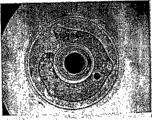
Figure 14 is the photo of top surface of the fluid dynamic-pressure bearing device of comparative example 1 of the present invention, and the liquid level that oiling agent is shown forms state.
Figure 15 is the photo of top surface of the fluid dynamic-pressure bearing device of comparative example 2 of the present invention, and the liquid level that oiling agent is shown forms state.
Figure 16 is the side cross-sectional view of schematic structure of conventional example of the capillary seal part of fluid dynamic-pressure bearing device.Figure 16 A is the general view of fluid dynamic-pressure bearing device.Figure 16 B is the part enlarged view of the capillary seal part of Figure 16 A.
Figure 17 is the side cross-sectional view of schematic structure of another conventional example that the capillary seal part of fluid dynamic-pressure bearing device is shown.
Figure 18 is the side cross-sectional view of schematic structure of another conventional example that the capillary seal part of fluid dynamic-pressure bearing device is shown.
Embodiment
(A) fluid dynamic-pressure bearing device
(1) first embodiment
The first embodiment of the present invention is described with reference to the accompanying drawings.Fig. 1 illustrates the schematic structure according to the fluid dynamic-pressure bearing device of the first embodiment of the present invention.Figure 1A is the side cross-sectional view of fluid dynamic-pressure bearing device, and Figure 1B is the side elevation along the fluid dynamic-pressure bearing device shown in the direction of the arrow A of Figure 1A.
At first, the general structure of illustrated example fluid dynamic-pressure bearing device 1.Fluid dynamic-pressure bearing device 1 has bearing part 20 hollow, substantially cylindrical, its swivel bearing running shaft (spindle unit) 10.Cylindrical seal parts 30 join bearing part 20 to, so that cover the upper end part of bearing part 20.Sealed member 30 has roof 31 and the column part 32 integrally formed with roof 31.In the roof 31 of sealed member 30, form outstanding hole 31a, wherein this outstanding hole is passed in the upper end part of running shaft 10.In the column part 32 of sealed member 30, form vent hole 32a.Packaged unit 40 joins the under shed part 21 of bearing part 20 to.
Between the interior perimeter surface of bearing part 20 and column part 32, form the first capillary seal part 50.The first capillary seal part 50 has conical cross-section, and it expands downwards vertically.Between the conical surface 11a of the interior perimeter surface of the outstanding hole 31a of sealed member 30 and running shaft 10, form the second capillary seal part 60, as described below.The second capillary seal part 60 has conical cross-section, and it upwards expands vertically.Radial dynamic pressure groove 20a is formed on the interior perimeter surface of bearing part 20, and thrust dynamic pressure grooves 40a (first thrust dynamic pressure grooves) is formed on the top surface of packaged unit 40.And, form through hole 20b and make it pass two end surfaces of bearing part 20 vertically.
Between running shaft 10 and bearing part 20, form radial bearing gap 71.Between running shaft 10 and packaged unit 40, form thrust-bearing gap 72. Bearing play 71,72 all is the microgap.Between the upper end face of the inner surface of the roof 31 of sealed member 30 and bearing part 20, form oiling agent memory gap 73.Oiling agent memory gap 73 has conical cross-section, and it radially outwards expands.Through hole 20b, radial bearing gap 71, thrust-bearing gap 72, oiling agent memory gap 73, the first capillary seal part 50 and the second capillary seal part 60 communicate mutually, and oiling agent 80 is filled therein continuously.And, because of capillarity can promote oiling agent, and from the first capillary seal part 50 oiling agent is supplied to the bearing play from the first capillary seal part 50 reliably through oiling agent memory gap 73, thereby gap size in the first capillary seal part 50 radially is arranged to greater than oiling agent memory gap 73 gap size vertically.
Filling method below for example utilizing, oiling agent is filled in first embodiment's the fluid dynamic-pressure bearing device.Just, in incomplete fluid dynamic-pressure bearing device, the parts of assembling except that sealed member 30, and the gap in the bearing part 20 becomes vacuum basically.Then, utilize distributor the oiling agent 80 of prearranging quatity to be supplied to the upper end face of bearing part 20.After the opening 22 in radial bearing gap 71 and through hole 20b were covered by oiling agent, if external pressure is got back in the outside of bearing part 20, then outside and the pressure reduction between the inside because of bearing part 20 was pushed to oiling agent 80 in the gap.Continuous then fill bearing clearance 71,72 of oiling agent and through hole 20b.In this stage, under state because of surface stress rising oiling agent liquid level, at the upper end face storage oiling agent 80 of bearing part 20, this oiling agent is that the filling first capillary seal part 50, oiling agent memory gap 73 and the second capillary seal part 60 are required.Here, when sealed member 30 joins bearing part 20 to and suppresses downwards, along with the gap smaller between the upper end face of the inner surface of the roof 31 of sealed member 30 and bearing part 20, then radially suppress and extrude the oiling agent of storing on the upper end face of bearing part 20 80, and liquid level finally moves to the first capillary seal part 50.Then, under the state that sealed member 30 is located vertically, along the whole circumference same position formation liquid level in the axial direction of the first capillary seal part 50.Therefore, can form liquid level stable, uniform oiling agent 80.And, in following arbitrary other embodiment, can utilize this filling method to obtain identical effect.
A plurality of parts of fluid dynamic-pressure bearing device 1 will be described below.Running shaft 10 has axle main body 11 and the flange part 12 that forms below axle main body 11.Axle main body 11 has cylinder with large diameter part 13, tapering part 14 and the small diameter cylinders part 15 that begins to set gradually from the bottom, and 13-15 is integrally formed for these parts.In tapering part 14, form conical surface 11a, its diameter upwards reduces vertically.The lower end of conical surface 11a is connected to the upper end of cylinder with large diameter part 13.In addition, the diameter of the upper end of conical surface 11a is greater than the diameter of small diameter cylinders part 15.
Bearing part 20 forms bearing part hollow, substantially cylindrical.In the bottom of bearing part 20, form under shed part 21, it joins packaged unit 40 to.At the upside of bearing part 20, form upper shed part 22, the core 14 of small diameter cylinders part 15 and running shaft 10 passes this upper shed part.On the interior perimeter surface of bearing part 20, form radial dynamic pressure groove 20a.The through hole 20b that forms passes two top surfaces of bearing part 20 vertically.Through hole 20b is convenient to lubricant circulates, and the internal differential pressure that produces between bearing play and oiling agent of slowly-releasing.Between the interior perimeter surface of bearing part 20 and running shaft 10, form radial bearing gap 71.The shape in this radial bearing gap 71 is corresponding to the outer surface of the cylinder with large diameter part 13 of axle main body 11.By the oiling agent 80 of filling in radial dynamic pressure groove 20a, radial bearing gap 71 and the radial bearing gap 71, constitute the radial bearing part.In the radial bearing part, because the operation of radial dynamic pressure groove 20a, the dynamic pressure that produces oiling agent, wherein this oiling agent receives radial load.Above-mentioned can be current known shape or any shape of exploitation afterwards in dynamic pressure groove field with the shape of thrust dynamic pressure grooves radially.
Figure 10 illustrates the schematic structure of sealed member shown in Figure 1 30.In the following description, in Figure 10, adopt the reference character identical with Fig. 1.Figure 10 A is the top surface figure of the roof 31 of sealed member 30, and Figure 10 B is the cross-sectional view along the line A-A cross section of Figure 10 A.Sealed member 30 can and be handled by promotion and form, and forms cylinder form, and wherein roof 31 and column part 32 are integrally formed.In roof 31, in be formed centrally outstanding hole 31a, on the internal surface of roof 31, form three projection 31b of the upper end face of contact bearing parts 20.Projection 31b have by contact form the concrete size that does not have irreqularity basically bearing upper end face and locate the function of sealed member 30 vertically.Vent hole 32a can be formed near column part 32 centers.Vent hole 32a sets up contact between the liquid level of the oiling agent 80 of the first capillary seal part 50 and environment.
Sealed member 30 is located such that the upper end face of the internal surface of roof 31 towards bearing part 20, and the small diameter cylinders part 15 of the upper end part of tapering part 14 and running shaft 10 is passed outstanding hole 31a.Vent hole 32a is positioned at below the upper end face of bearing part 20.Sealed member 30 joins bearing part 20 to, so that cover the upper end part of bearing part 20, and utilizes binder 33 to fix.
The first capillary seal part 50 and oiling agent memory gap 73 communicate, and are formed between the interior perimeter surface of the conical surface 20c on top of outer surface of bearing part 20 and sealed member 30, and the interior perimeter surface of sealing parts 30 is towards conical surface 20c.The first capillary seal part 50 forms the capillary pipe structure of cross section taper, and this capillary pipe structure is widened downwards vertically.The liquid level of the oiling agent 80 in the first capillary seal part 50 is positioned at the vent hole 32a top of column part 32 vertically.
The second capillary seal part 60 communicates with radial bearing gap 71 and oiling agent memory gap 73 respectively, and is formed between the conical surface 11a of the interior perimeter surface of outstanding hole 31a of sealed member 20 and running shaft 10.The second capillary seal part 60 forms the capillary pipe structure of cross section taper, and this capillary pipe structure is upwards widened vertically.
Oiling agent 80 occupies through hole 20b, radial bearing gap 71, thrust-bearing gap 72, oiling agent memory gap 73, the first capillary seal part 50 and the second capillary seal part 60, and they all communicate with each other.Oiling agent 80 is recycled to oiling agent memory gap 73 from radial bearing gap 71 and thrust-bearing gap 72.Because capillarity, the generation active force upwards promotes the oiling agent in the first capillary seal part 50 vertically.Particularly, in the first capillary seal part 50, surface stress by balance oiling agent 80 and the external pressure by vent hole 32a, the liquid level position of oiling agent 80 remains on the top of vent hole 32a vertically.Because this effect of the first capillary seal part 50 suppresses oiling agent 80 and leaks into the outside.And, in the second capillary seal part 60, because capillarity produces active force and promotes oiling agent 80 vertically downwards.Because this effect of the second capillary seal part 60 suppresses oiling agent 80 and leaks into the outside.
In first embodiment's fluid dynamic-pressure bearing device 1, between the interior perimeter surface of the outer surface of bearing part 20 and sealed member 30, form the first capillary seal part 50, this first capillary seal partly forms the cross section conical in shape, it is widened downwards vertically, and communicates with oiling agent memory gap 73.Therefore, because capillarity in the first capillary seal part 50, produces active force and promotes oiling agent 80 vertically downwards, thereby suppresses the outside that oiling agent 80 leaks into fluid dynamic-pressure bearing device.Therefore, can suppress the minimizing of the memory space of oiling agent 80, and the interior pollution of recording disk drive device that can suppress to have this fluid dynamic-pressure bearing device 1.And, because the liquid level of oiling agent 80 can be arranged in the first capillary seal part 50, be formed uniformly the liquid level of oiling agent 80 so can stablize.Therefore, the additional lubrication agent 80 of storage can supply to radial bearing part and thrust-bearing part reliably in the first capillary seal part 50 and the oiling agent memory gap 73.
And, according to first embodiment, independently constitute the first capillary seal part 50 by bearing means, and rotor hub that need not traditional spindle motor.Therefore, can solve the problem that in the bearing means that adopts the conventional rotors hub, produces.In addition, the oiling agent memory gap 73 and the first capillary seal part 50 communicate, and are formed between the internal surface of roof 31 of the upper end face of bearing part 20 and sealed member 30.Therefore, can be with the whole upper end face of the first capillary seal part 50 and bearing part 20 as the oiling agent storage space.The result is, can increase the memory space of additional lubrication agent 80, and the capillary seal part that can not extend vertically, this is different from traditional capillary seal part, the tradition capillary seal partly is formed on the opening in gap between the interior perimeter surface of the outer surface of running shaft and bearing part, also can not increase the diameter of bearing part, this also is different from traditional capillary seal part, and traditional capillary seal partly is formed between the upper end face of thin plate and bearing part.Along with the storage capacity increase of additional lubrication agent 80, the oiling agent poor efficiency that produces because of the oiling agent natural evaporation causes the time of bearing end in working life to be prolonged.Therefore, can improve the working life of fluid dynamic-pressure bearing device 1, and the size that can reduce fluid dynamic-pressure bearing device 1.
And, in first embodiment's fluid dynamic-pressure bearing device 1, in the second capillary seal part 60,, leak into the device outside so that can suppress oiling agent because capillarity produces active force promotion oiling agent 80 and moves downward vertically.
And the first capillary seal part 50 can adopt the open part of vent hole 32a conduct and environmental communication, thereby the opening area of this capillary seal part is less than conventional apparatus.Therefore, can suppress evaporation, leakage and the pollution of oiling agent 80.Therefore, can further suppress reducing of oiling agent 80 memory spaces, and the interior pollution of recording disk drive device that can further suppress to have fluid dynamic-pressure bearing device 1.
In addition, oiling agent memory gap 73 forms the cross section conical in shape, and it is radially to external conical shapeization, thereby in oiling agent memory gap 73, because capillarity, active force is applied to oiling agent 80, radially inwardly promotes oiling agent.Active force also affacts the oiling agent 80 in the first capillary seal part 50, and this first capillary seal part 50 and oiling agent memory gap 73 communicate, thereby upwards promote oiling agent vertically.Therefore, can effectively suppress oiling agent 80 and leak into the device outside.
And, by allowing projection 31b touch and locating sealed member 30 vertically, can there be the formation first capillary seal part 50 and the oiling agent memory gap 73 of irreqularity according to concrete size to the upper end face of bearing part 20.
(2) second embodiments
Below with reference to Fig. 2 the second embodiment of the present invention is described.Fig. 2 illustrates the schematic structure of fluid dynamic-pressure bearing device 2 according to a second embodiment of the present invention.Fig. 2 A is the side cross-sectional view of fluid dynamic-pressure bearing device 2, and Fig. 2 B is the side elevation along the fluid dynamic-pressure bearing device 2 shown in the direction of the arrow A of Fig. 2 A.And, among the second to the 11 embodiment below, adopt the reference character identical to represent identical parts, and will the structure and the operation of these same parts be repeated no more with first embodiment.In second embodiment's fluid dynamic-pressure bearing device 2, do not form the such vent hole 32a of first embodiment, but form groove 32b.Groove 32b is formed on the lower end of column part 32, the position correspondence of the position of the upper end of groove 32b and first embodiment's vent hole 32a.In a second embodiment, the amount of oiling agent 80 can come vision to check by groove 32b.
(3) the 3rd embodiments
Below with reference to Fig. 3 the third embodiment of the present invention is described.Fig. 3 is the side cross-sectional view of schematic structure of the fluid dynamic-pressure bearing device 3 of a third embodiment in accordance with the invention.In the 3rd embodiment's fluid dynamic-pressure bearing device 3, only come tectonic axis main body 11 by small diameter cylinders part 15 and cylinder with large diameter part 16, omitted first embodiment's tapering part 14.Just, in the 3rd embodiment, the position of the upper end of corresponding first embodiment's of upper end position of the shape of the cylinder with large diameter part 16 of axle main body 11 tapering part 14.Therefore, omit polishing treatment, and be easy to handle running shaft 10 tapering part 14.
(4) the 4th embodiments
Below with reference to Fig. 4 the fourth embodiment of the present invention is described.Fig. 4 is the side cross-sectional view of schematic structure of the fluid dynamic-pressure bearing device 4 of a fourth embodiment in accordance with the invention.In the 4th embodiment, on first embodiment's sealed member 30, form annular projection 31c, it is along the interior circumferential upper process of nipple hole 31a.Therefore, can leak into the outside thereby can further suppress oiling agent 80 so that oiling agent 80 can further move vertically in the second capillary seal part 60.
(5) the 5th embodiments
Below with reference to Fig. 5 the fifth embodiment of the present invention is described.Fig. 5 is the side cross-sectional view of the schematic structure of fluid dynamic-pressure bearing device 5 according to a fifth embodiment of the invention.The 5th embodiment's fluid dynamic-pressure bearing device 5 is provided with case member 90 hollow, substantial cylindrical, and bearing part 20 joins the interior perimeter surface of case member 90 to.Case member 90 can be handled by excision and form.Packaged unit 40 joins the under shed part 91 of case member 90 to, and the upper end face of packaged unit 40 is in the face of the lower surface of flange part 12.Sealed member 30 joins the upper end part of the outer surface of case member 90 to.By allowing the rear surface of column part 32 of sealed member 30 touch, make sealed member 30 locate vertically to step portion 92.Locate sealed member 30 in this way vertically, can omit the step that forms projection 31b among first embodiment.Therefore, can not lose the positional accuracy of sealed member 30 vertically, can be easy to handle sealed member 30.And, by the structure that bearing part 20 and packaged unit 40 join case member 90 to is set, can simplifies the shape of each parts, and can simplify processing procedure.Simultaneously, by shifting to an earlier date each parts of standardization setting and storing these parts, can carry out multiple combination.Even need adjust the design of bearing means, also can make rapid response.Therefore, can reduce manufacture cost.
(6) the 6th embodiments
Below with reference to Fig. 6 the sixth embodiment of the present invention is described.Fig. 6 is the side cross-sectional view of the schematic structure of fluid dynamic-pressure bearing device 6 according to a sixth embodiment of the invention.In the 6th embodiment's fluid dynamic-pressure bearing device 6, omitted the step portion 92 of the 5th embodiment's case member 90, thereby sealed member 30 joins the outer surface of bearing part 20 to.The upper end face 90a of the rear surface contact case member 90 of the column part 32 of sealed member 30, thus can locate sealed member 30 vertically.Therefore, can be easy to handle case member 90, and can not lose sealed member 30 positional accuracy vertically, and can omit the step that forms the step portion 92 of case member 90 among the 5th embodiment.
(7) the 7th embodiments
Below with reference to Fig. 7 the seventh embodiment of the present invention is described.Fig. 7 is the side cross-sectional view of the schematic structure of fluid dynamic-pressure bearing device 7 according to a seventh embodiment of the invention.The 7th embodiment is a kind of modified example of the 5th embodiment.The cylindrical house part 90 of the 7th embodiment's fluid dynamic-pressure bearing device 7 has the bottom.In case member 90, integrally formed the 5th embodiment's packaged unit 40 and case member 90.And fluid dynamic-pressure bearing device 7 has the slider 100 (isolating part) between the upper surface of the diapire of the rear surface of bearing part 20 and case member 90, thereby the joint clearance 101 that forms joins the flange part 12 of running shaft 10 to.And, in fluid dynamic-pressure bearing device 7, do not adopt the conical surface 20d that forms on first embodiment's the upper end face of bearing part 20, but on the inner surface of the roof 31 of sealed member 30, form conical surface 31d.Conical surface 31d radially outwards axially raises from nipple hole 31a.And, do not adopt the conical surface 20c that forms on first embodiment's the outer surface upside of bearing part 20, but on the inner surface of the column part 32 of sealed member 30, form conical surface 32b.Conical surface 32b begins to expand from conical surface 31d downwards vertically.In addition, on the inboard of the end portion of the column part 32 of the upper end part of the outer surface that joins case member 90 to, the periphery of formation is connected to conical surface 31d.By forming this structure, omitted the conical surface and the step portion of bearing part 20, and outer surface.By with the 5th embodiment's same way as, except case member 90 and bearing part 20, also standardization setting slider 100 and storing in advance can respond rapidly and design adjustment.
(8) the 8th embodiments
Below with reference to Fig. 8 the eighth embodiment of the present invention is described.Fig. 8 is the side cross-sectional view according to the schematic structure of the fluid dynamic-pressure bearing device 8 of the eighth embodiment of the present invention.The 8th embodiment is first embodiment's a modified example.In the 8th embodiment, on rear surface, form thrust dynamic pressure grooves 20e in the face of the bearing part 20 of the upper surface of the flange part 12 of first embodiment's running shaft 10, the dynamic pressure of its generation receives load along thrust direction.In this case, by the dynamic pressure of the thrust direction that on the upper surface of flange part 12, produces, be equilibrated at the dynamic pressure of the thrust direction that produces on the lower surface of flange part 12, thereby running shaft 10 is non-rising, but can stablizes rotation.
(9) the 9th embodiments
Below with reference to Fig. 9 the ninth embodiment of the present invention is described.Fig. 9 is the side cross-sectional view according to the schematic structure of the fluid dynamic-pressure bearing device 9 of the ninth embodiment of the present invention.Fluid dynamic-pressure bearing device 9 has case member 90 hollow, substantially cylindrical, and bearing part 20 joins the interior perimeter surface of case member 90 to.Form case member 90 by promotion or extrusion process, therefore cheap than the 5th embodiment's case member.Packaged unit 40 joins the under shed part 91 of case member 90 to, and the upper end face of packaged unit 40 is in the face of the lower surface of the flange part 12 of running shaft 10.And, between the upper end face of the rear surface of bearing part 20 and packaged unit 40, slider 100 is set, so that forming, joint clearance 101 joins flange part 12 to.
And on the interior perimeter surface of the outer surface of bearing part 20 and sealed member 30, peripheral groove 20f, the 32c of formation are toward each other.Peripheral groove 20f, 32c are positioned at more than the vent hole 32a of the following and sealed member 30 of the liquid level of the first capillary seal part 50.In the position that is positioned at below the peripheral groove 20f, with oil resistance agent 110 coatings to the outer surface of bearing part 20, the position below peripheral groove 32c, with the oil resistance agent coating on the interior perimeter surface of sealed member 30.Oil resistance agent 110 is for example formed by the fluorine material.
On the outer surface of bearing part 20, form and circumferentially keep groove 111 (the circumferential maintenance groove that is used for binder).Between the interior perimeter surface of the end of the column part 32 of the outer surface of the upper end part that circumferentially keeps groove 111 and sealed member 30, be formed for first retaining part 121 of binder.Between the interior perimeter surface of the upper end part of the outer surface of the end portion that circumferentially keeps groove 111 and case member 90, be formed for second retaining part 122 of binder.By remaining on the binder in first retaining part 121, sealed member 30 is fixed to bearing part 20.By remaining on the binder in second retaining part 122, case member 90 is fixed to bearing part 20.
In the 9th embodiment, even because of exterior vibration or vibration, the liquid level of the oiling agent 80 of the capillary seal part 50 of winning is moved down rapidly, also can leak self-ventilation hole 32a thereby can further suppress oiling agent 80 by peripheral groove 20f, 32c and oil resistance agent 110 effective sealed-in lubricants 80.And peripheral groove 20f, 32c also are used for mark coating position in coating oil resistance agent 110.And, near location first and second retaining parts 121,122, can on outer surface, form peripheral groove 20f, 32c by respectively, this outer surface is away from the open part 22 of bearing part 20 relatively.Therefore, when applying binder, can effectively suppress the problem of adhesive coating to non-expectation part, and the problem that binder is applied to interior perimeter surface from the open part 22 of bearing part 20.And, can simplify the part that is filled with binder.And, all binders can be once injected, thereby binder can be easy to inject.
(10) the tenth embodiments
(B) spindle motor
The following describes the spindle motor of the fluid dynamic-pressure bearing device 1-9 that adopts first to the 9th embodiment.Figure 11 is the side cross-sectional view of schematic structure of the tenth embodiment's that is applied to of first embodiment's fluid dynamic-pressure bearing device spindle motor 200.And spindle motor 200 is not limited to first embodiment's fluid dynamic-pressure bearing device 1, but can also adopt second to the 9th embodiment's fluid dynamic-pressure bearing device 2-9.
Upper end at running shaft 10 forms screw, and this screw is not shown specifically, and fixedly the holding element of indicator is screwed into this screw.And the flexible cord plate is fixed to the surface of pedestal 210, and when the output terminal by the line plate applied the control electric current to stator 220, the rotor assembly body that is formed by parts such as rotor hub 231, rotor magnet 232, running shafts 10 rotated with respect to stator 220.
In above-mentioned spindle motor 200, when running shaft 10 rotations, attract the rotor assembly body by axial magnetic, this is axially opposite with the direction of the thrust dynamic pressure of the generation of the thrust dynamic pressure grooves 40a in the fluid dynamic-pressure bearing device 1.The thrust dynamic pressure equilibrium of forces power that thrust dynamic pressure grooves 40a produces is making a concerted effort of magnetic force and gravity.Spindle motor 200 is non-rising, thereby can stable support.
When the 8th embodiment's fluid dynamic-pressure bearing device 8 is applied to spindle motor 200, rather than first embodiment's fluid dynamic-pressure bearing device 1, fluid dynamic-pressure bearing device 8 has a pair of thrust dynamic pressure bearing 20e, 40a, their mutual balances, attract plate 240 thereby needn't be provided with, this attraction plate attracts rotor 230 by magnetic force.Therefore, can use still less parts.
(11) the 11 embodiments
(C) recording disk drive device
The following describes the disk drive device 300 as recording disk drive device of the spindle motor 200 that adopts the tenth embodiment.Figure 12 is the side cross-sectional view of schematic structure of the 11 embodiment's recording disk drive device 300.In disk drive device 300, coating member 301 is set, the spaces in the pedestal 210 of its spindle motor 200 by sealing the tenth embodiment form the clean of few dust.Coating member 301 and pedestal 210 form the housing of disk drive device 300.Therefore, the part of the housing of the part of pedestal 210 formation spindle motors 200 and disk drive device 300.The stator 220 of spindle motor 200 and comprise that the main body of the spindle motor 200 of rotor 230 remains on the enclosure interior of disk drive device 300.
On the outer surface of rotor hub 231, two disks 304 (indicator) are installed.By centrepin being joined to along the screw of the axial formation of the small diameter cylinders part 15 of running shaft 10, and by fixed clamp member 303, thereby disk 304 is fixed to rotor hub 231.By doing like this, along rotor hub 231 spinning disks 304.And in the 11 embodiment, two disks 304 are installed to rotor hub 231, but the quantity of disk is not limited thereto.
In addition, disk drive device 300 has magnetic head 306 (write head), and the information of its read-write disk 304 also has the arm 307 of supporting magnet 306 and the voice coil motor 308 that magnet 306 and arm 307 is moved to the precalculated position.The magnet 310 that voice coil motor 308 has coil 309 and is provided with respect to coil 309.
Correct position on pedestal 210, magnetic head 306 are installed to the top end part of head stack 311, and this head stack is fixed to the arm 307 of rotatable supporting.A pair of magnetic head 306 up and down is arranged to each disk 304 of interlayer, and the information on read-write disk 304 two sides.And, in the 11 embodiment, two disks 304 are arranged, thereby two pairs of write heads 306 are set.In addition, in the 11 embodiment, spindle motor 200 is applied to disk drive device 300, but this does not limit the present invention.For example, spindle motor 200 can also be applied to the recording disk drive device of the indicator that drives CD for example or DVD.
The following describes some prototype embodiments.
(1) assessment is positioned at the liquid level state of the oiling agent of bearing part upper end face
[prototype embodiment 1]
Prototype embodiment 1 is a kind of fluid dynamic-pressure bearing device, and wherein the transparent resin sealed member is mounted to and can observes the liquid level state, and setting and the identical sealed member of above-mentioned first embodiment of the present invention.Therefore, adopt the filling method described in first embodiment, can utilize oiling agent to fill gap in embodiment 1 the fluid dynamic-pressure bearing device.Just, under the state that has assembled all other parts except that resin-sealed parts, the inside of the bearing part of this imperfect fluid dynamic-pressure bearing device is essentially vacuum.By adopting distributor, the oiling agent of prearranging quatity is applied to the upper end face of bearing part, oiling agent covers the opening and the through hole of bearing play.Then, external pressure is got back in the outside of bearing part, and because of the pressure reduction between this external pressure and the interior pressure, oiling agent is got back to bearing play and through hole.In this stage, keep the oiling agent of aequum at the upper end face of bearing part, so that occupy first capillary seal part, oiling agent memory gap and the second capillary seal part under the state that liquid level raises making because of surface stress.Then,, carry out location vertically, and form liquid level in the precalculated position of first capillary seal part by joining sealed member to bearing part.Figure 13 shows this result.Figure 13 is the photo of side surface of prototype embodiment's 1 of the present invention fluid dynamic-pressure bearing device, and the oiling agent liquid level between bearing part and sealed member is shown.As shown in figure 13, in prototype embodiment 1, confirm along the whole circumference of first capillary seal part in the axial direction the oiling agent liquid level be formed on same position.By repeatedly investigating this equal state, can obtain identical result.Just, in prototype embodiment 1, form stable, uniform oiling agent liquid level along first capillary seal whole circumference partly.
[comparative example 1,2]
Utilize the same axis bearing apparatus among the prototype embodiment 1, adopt the filling method identical with prototype embodiment 1, supply is than prototype embodiment 1 prearranging quatity lubricant quantity still less, so that form liquid level at the upper end face of bearing part, and the state that observes liquid level.In result shown in Figure 14 and 15.Figure 14 and 15 is photos of top surface of the fluid dynamic-pressure bearing device of comparative example 1,2 of the present invention, the isohypse that the liquid level that oiling agent is shown forms at the upper end face of bearing part.In this case, if essentially identical distance forms liquid level along the center, hole of the whole peripheral distance bearing part of bearing part, just,, then can think to have formed uniform oiling agent liquid level if the isohypse shape is similar to circumference.In comparative example 1,2, the employing still oiling agent of capacity still less forms the liquid level of the upper end face of bearing part.Yet, can know from Figure 14 and 15 and to see that the liquid level of oiling agent is uneven liquid level that the isohypse of the liquid level of seeing from top surface is irregularly shaped, does not form identical shape usually.It is discontinuous in center hole edge that Figure 14 illustrates the isohypse of liquid level.In Figure 15, adopt than the oiling agent of Figure 14 oiling agent of volume slightly, but through hole be can't help oiling agent and is covered.And bubble is by the part at center hole edge, the discontinuous filling of oiling agent.In this case, when bearing part rotated, air can pass through oiling agent, and lubricant starvation is to supply to the bearing play; The phenomenon that the bearing means jam therefore, can occur.
Therefore, compare,, form stable, uniform oiling agent liquid level, confirm that the oiling agent in the bearing means can supply to radial bearing reliably according to prototype embodiment 1 with comparative example 1,2.When utilizing oiling agent to fill, be formed on the upper end face of bearing part, even at bearing means stored capacity oiling agent, also confirm to produce such state of discontinuous packing lubrication agent, air during rotation enters radial bearing part and thrust-bearing part, and does not supply with enough oiling agents.Therefore, the working life of fluid dynamic-pressure bearing device is shorter than expection.Therefore, if oiling agent is filled into the gap so that partly form liquid level at first capillary seal, then working life can be elongated, and can obtain more stable supporting working life.
(2) the vibration test result of spindle motor
[prototype embodiment 2-19]
Spindle motor to fluid dynamic-pressure bearing device 9 with ninth embodiment of the present invention carries out vibration test.According to prototype embodiment 2-10, the spindle motor of the ninth embodiment of the present invention that is in steady state is applied vibrations.According to prototype embodiment 11-19, the spindle motor of the ninth embodiment of the present invention that is in rotation status is applied vibrations.Verification splashes the inhibition effect for the oiling agent of vibrations.In the vibration test result of the 2-10 of prototype embodiment shown in the form 1, in the vibration test result of the 11-19 of prototype embodiment shown in the form 2.
[form 1]
The vibration test result of stabilize spindle motor

[form 2]
The vibration test result of rotary main shaft motor
In vibration test, the SM110 type vibration test machine that adopts Endevco to make.For test condition, adopt three kinds of different position application to above-mentioned test machine for the assembly of spindle motor location, just, upwards towards; Downwards towards; Side direction towards, shown in form 1 and 2.Assembly location " upwards towards; Downwards towards; Side direction towards " mean fluid dynamic-pressure bearing device bearing part upper shed partly upwards towards; Downwards towards; Side direction towards.And, apply vibrations from facing down, measure shockproofness by maximum acceleration figure.Shockproofness is divided into five grades, from 800G to 1500G, and carries out test.For acceleration, adopt half sinusoid, wherein in the time of 1ms, accelerate to maximum acceleration figure from zero, get back to zero acceleration figure then.Adopt the reason of this test method to be, decide location that the mobile amplitude of oiling agent in fluid dynamic-pressure bearing device applies direction according to shockproofness and fluid dynamic-pressure bearing device with respect to vibrations or the like, and this method has been considered these factors.
As the product of test, preparation has 18 spindle motors (prototype embodiment 2-19) of the fluid dynamic-pressure bearing device of the ninth embodiment of the present invention.At nine spindle motors of steady state test, at nine spindle motors of rotation status test.For each these state, for upwards, downwards and side direction assembly location, three of adopting nine spindle motors respectively.For the vibration test of each test products, adopt five levels of acceleration continuously.
And in prototype embodiment 2-19, vibrations (acceleration) application process of the order of using according to from small to large vibrations (acceleration) is carried out test.This is because oiling agent becomes more and more serious with respect to the condition of the positional stability of vibrations in proper order according to this.And, carry out this vibration test, up to quickening to arrive maximum value 1500G, perhaps up in test products, finding oil leakage phenomenon always.
Can know from form 1 and 2 and to see that test result shows, under steady state, even add the vibrations of 1500G, does not find that also oiling agent leaks, and under rotation status, even add the vibrations of 1400G, does not find that also oiling agent leaks.Traditionally, when dish device, CD-ROM device or the like are installed in notebook computer or the portable terminal device, vibration resistance with spindle motor of fluid dynamic-pressure bearing device requires to be approximately 1000G, but sealing configuration for the ninth embodiment of the present invention, even vibrations also can illustrate superior oiling agent and splash the inhibition effect greater than 1000G.In form, " leakage of oil " is illustrated in the test process actual the confirmation oil leakage phenomenon, and " OK " is illustrated in and do not have oil leakage phenomenon in the test process.By adopting the such visual observation means of microscope to confirm whether leakage of oil.
Though with reference to concrete exemplary embodiment the present invention is described, these embodiments are illustrative, and not restrictive.Within the spirit and scope of the present invention, can make multiple variation, alternative and improvement.
Claims (24)
1. fluid dynamic-pressure bearing device comprises:
Spindle unit;
The bearing part of supporting shaft part, and can between spindle unit and bearing part, rotate relatively;
Sealed member with roof, this roof has outstanding hole, and this outstanding hole is passed in the upper end portion of spindle unit, and sealed member is arranged to cover the upper end portion of bearing part;
The packaged unit of the underpart of sealing bearing part; And
Bearing play, this bearing play comprise the dynamic pressure groove that is respectively formed between spindle unit and the bearing part and between spindle unit and the packaged unit; Wherein:
The radial dynamic pressure groove is formed in one of the outer surface of spindle unit or interior perimeter surface of bearing part, and the radial dynamic pressure groove produces the kinetic pressure that radially receives load;
First thrust dynamic pressure grooves be formed on spindle unit in one of upper surface of lower surface or packaged unit, and first thrust dynamic pressure grooves produces the kinetic pressure that receives load along thrust direction;
The oiling agent memory gap is formed between the internal surface of roof of the upper end face of bearing part and sealed member;
First capillary seal partly is formed between the interior perimeter surface of the outer surface of bearing part and sealed member, and first capillary seal part that forms the cross section taper is widened downwards;
Second capillary seal partly is formed between the interior perimeter surface in the outer surface of spindle unit and outstanding hole; And
Bearing play, second capillary seal part, oiling agent memory gap and first capillary seal partly mutually combine, and are filled by oiling agent.
2. fluid dynamic-pressure bearing device according to claim 1, wherein sealed member comprises sidewall, and vent hole is formed in the sidewall of sealed member, and this vent hole is positioned under the liquid level of the oiling agent of filling first capillary seal part.
3. fluid dynamic-pressure bearing device according to claim 1 and 2, second capillary seal that wherein forms the cross section taper is partly upwards widened.
4. fluid dynamic-pressure bearing device according to claim 1, wherein the cross section conical in shape of oiling agent memory gap formation is radially outwards widened.
5. fluid dynamic-pressure bearing device according to claim 1 wherein forms annular projection on the outstanding hole of sealed member, this annular projection begins to upper process from outstanding hole in interior week, and extends upward the second capillary seal part vertically.
6. fluid dynamic-pressure bearing device according to claim 1, wherein:
On the internal surface of the roof of sealed member, form three with upper process; And
The upper end face of these projection contact bearing parts, thereby the axially locating of realization sealed member.
7. fluid dynamic-pressure bearing device according to claim 2, wherein:
In the interior perimeter surface of the outer surface of bearing part and sealed member, form opposed facing peripheral groove respectively; And
These peripheral grooves all are arranged on the liquid level below of first capillary seal part and the vent hole top of sealed member.
8. fluid dynamic-pressure bearing device according to claim 7 wherein below peripheral groove, arrives the outer surface of bearing part and/or the interior perimeter surface of sealed member with the oil resistance agent coating.
9. fluid dynamic-pressure bearing device according to claim 2, wherein vent hole is the groove of rear surface that extends downwardly into the sidewall of sealed member, and with the form that acts on vision examination oiling agent liquid level position.
10. fluid dynamic-pressure bearing device according to claim 1 also comprises:
The hollow shell parts, the length overall of these hollow shell parts is shorter than bearing part;
Wherein bearing part is outstanding from the upper end part of case member, and bearing part joins the interior perimeter surface of case member to.
11. fluid dynamic-pressure bearing device according to claim 10, wherein:
Sealed member joins the upper end part outer surface of bearing part to, and the upper end face of contact case member, thereby realizes the axially locating of sealed member.
12. fluid dynamic-pressure bearing device according to claim 10, wherein:
On the outer surface of the upper end face of case member, can form step portion; And
The sealing part bonding arrives the outer surface of the upper end part of case member, and contacts this step portion, thereby realizes the axially locating of sealed member.
13. fluid dynamic-pressure bearing device according to claim 1 also comprises:
The hollow shell parts, the length overall of these hollow shell parts is shorter than bearing part; Wherein:
Bearing part is outstanding from the upper end part of case member, and bearing part joins the interior perimeter surface of case member to;
Sealed member joins the outer surface of the upper end part of bearing part to;
Between the interior perimeter surface of the upper end part of the outer surface of bearing part and case member, form the first binder retaining part;
Between the interior perimeter surface of the end portion of the outer surface of bearing part and sealed member, form the second binder retaining part;
Binder is filled in this first and second binders retaining part; And
Case member and sealed member are fixed to bearing part by binder respectively.
14. fluid dynamic-pressure bearing device according to claim 13, wherein:
On the outer surface of bearing part, be formed for the circumferential maintenance groove of binder; And
Between circumferentially keeping the interior perimeter surface of upper end part of groove and case member, this forms the first binder retaining part; And
Between circumferentially keeping the interior perimeter surface of end portion of groove and sealed member, this forms the second binder retaining part.
15. fluid dynamic-pressure bearing device according to claim 10, wherein case member can be by assigning to constitute with the integrally formed tube of packaged unit.
16. fluid dynamic-pressure bearing device according to claim 10, wherein case member forms by drawing processing or extrusion process.
17. fluid dynamic-pressure bearing device according to claim 1, wherein sealed member forms by drawing to handle.
18. fluid dynamic-pressure bearing device according to claim 1, wherein through hole passes bearing part vertically, and this through hole is set up the contact between bearing play and the oiling agent memory gap.
19. fluid dynamic-pressure bearing device according to claim 1, wherein spindle unit comprises flange part.
20. fluid dynamic-pressure bearing device according to claim 19 wherein is provided with isolating part between bearing part and sealed member, thereby forms the joint clearance that joins flange part to.
21. fluid dynamic-pressure bearing device according to claim 19, wherein on the upper end face of the rear surface of bearing part respect to one another or flange part, form second thrust dynamic pressure grooves, this second thrust dynamic pressure grooves produces dynamic pressure so that receive load along thrust direction.
22. a spindle motor comprises:
Pedestal;
Be fixed to the stator of pedestal;
Rotor with rotor hub and rotor magnet, wherein rotor magnet joins rotor hub to and produces rotating magnetic field with stator is collaborative, and is arranged to rotate with respect to pedestal; And
The fluid dynamic-pressure bearing device of supporting rotor rotation, wherein:
Fluid dynamic-pressure bearing device is the described fluid dynamic-pressure bearing device of one of claim 1-20, and
Rotor is by the magnetic attraction of a direction, and wherein the direction of the thrust dynamic pressure that produces in first thrust dynamic pressure grooves in this direction and the fluid dynamic-pressure bearing device is opposite.
23. a spindle motor comprises:
Pedestal;
Be fixed to the stator of pedestal;
Rotor with rotor hub and rotor magnet, wherein rotor magnet joins rotor hub to and produces rotating magnetic field with stator is collaborative, and is arranged to rotate with respect to pedestal; And
The fluid dynamic-pressure bearing device of supporting rotor rotation, wherein:
Fluid dynamic-pressure bearing device is the described fluid dynamic-pressure bearing device of claim 21.
24. a magnetic recording drive unit comprises:
Indicator;
Read and/or the recording of information head of write record dish; And
The spindle motor of rotatable activation record dish, wherein:
Spindle motor is according to claim 22 or 23 described spindle motors.
Applications Claiming Priority (2)
| Application Number | Priority Date | Filing Date | Title |
|---|---|---|---|
| JP2004358324A JP4619763B2 (en) | 2004-12-10 | 2004-12-10 | Fluid dynamic bearing device, spindle motor provided with the fluid dynamic pressure bearing device, and recording disk drive |
| JP358324/2004 | 2004-12-10 |
Publications (2)
| Publication Number | Publication Date |
|---|---|
| CN101072954A CN101072954A (en) | 2007-11-14 |
| CN100543327C true CN100543327C (en) | 2009-09-23 |
Family
ID=36204351
Family Applications (1)
| Application Number | Title | Priority Date | Filing Date |
|---|---|---|---|
| CN200580042082.5A Active CN100543327C (en) | 2004-12-10 | 2005-11-30 | Fluid dynamic-pressure bearing device, spindle motor and recording disk drive device with fluid dynamic-pressure bearing device |
Country Status (5)
| Country | Link |
|---|---|
| US (1) | US7576947B2 (en) |
| JP (1) | JP4619763B2 (en) |
| CN (1) | CN100543327C (en) |
| DE (1) | DE112005002835T5 (en) |
| WO (1) | WO2006061684A1 (en) |
Families Citing this family (19)
| Publication number | Priority date | Publication date | Assignee | Title |
|---|---|---|---|---|
| JP4428364B2 (en) | 2006-07-05 | 2010-03-10 | ソニー株式会社 | Bearing unit and motor using the bearing unit |
| JP2008248916A (en) | 2007-03-29 | 2008-10-16 | Matsushita Electric Ind Co Ltd | Fluid bearing device, spindle motor having the same, and disk drive device |
| JP5151268B2 (en) * | 2007-06-25 | 2013-02-27 | 日本電産株式会社 | Motor and disk drive device |
| KR101439924B1 (en) * | 2007-07-31 | 2014-09-12 | 엔티엔 가부시키가이샤 | Fluid dynamic bearing device and its assembling method |
| JP5578346B2 (en) * | 2009-11-06 | 2014-08-27 | 日本電産株式会社 | Chucking device, brushless motor and disk drive device, and method of manufacturing chucking device |
| US20110019303A1 (en) * | 2008-05-26 | 2011-01-27 | Nidec Corporation | Fluid dynamic bearing apparatus, spindle motor, and disk drive apparatus |
| KR100997189B1 (en) * | 2008-11-14 | 2010-11-29 | 삼성전기주식회사 | Motor |
| KR101084826B1 (en) | 2010-05-19 | 2011-11-21 | 삼성전기주식회사 | Hydrodynamic bearing motor |
| KR101829724B1 (en) * | 2010-09-23 | 2018-02-19 | 보르그워너 인코퍼레이티드 | Vtg cartridge of an exhaust-gas turbocharger |
| KR101090029B1 (en) * | 2010-11-22 | 2011-12-05 | 삼성전기주식회사 | Motor and driving device of recording disk including the same |
| DE102010056251A1 (en) * | 2010-12-24 | 2012-06-28 | Minebea Co., Ltd. | Fluid bearing for spindle motor, has shaft that is rotatably mounted in relative to bearing bush by fluid dynamic radial bearing and hydrostatic thrust bearing about rotation axis |
| JP2012225386A (en) * | 2011-04-18 | 2012-11-15 | Ntn Corp | Fluid dynamic pressure bearing device |
| US20130342062A1 (en) * | 2012-06-22 | 2013-12-26 | Nidec Corporation | Motor for rotationally supporting a hard disk |
| JP2014105783A (en) * | 2012-11-28 | 2014-06-09 | Samsung Electromechanics Japan Advanced Technology Co Ltd | Rotary equipment |
| US8970984B1 (en) | 2014-04-29 | 2015-03-03 | Western Digital Technologies, Inc. | Grooved cylindrical seal with increased radial clearance for reduced cost disk drive spindle |
| DE102014019055A1 (en) * | 2014-12-22 | 2016-06-23 | Minebea Co., Ltd. | Fluid dynamic bearing system for pivotal mounting of a spindle motor |
| KR102048574B1 (en) * | 2018-08-23 | 2020-01-22 | 엘지전자 주식회사 | Motor and Manufacturing method of the same |
| KR102358176B1 (en) * | 2019-11-18 | 2022-02-08 | 엘지전자 주식회사 | Motor |
| CN113644780B (en) * | 2021-07-28 | 2022-06-10 | 智新科技股份有限公司 | Motor positioning device |
Family Cites Families (13)
| Publication number | Priority date | Publication date | Assignee | Title |
|---|---|---|---|---|
| JP2937833B2 (en) | 1994-11-15 | 1999-08-23 | 株式会社三協精機製作所 | Bearing sealing device |
| JPH08331796A (en) | 1995-06-02 | 1996-12-13 | Matsushita Electric Ind Co Ltd | Motor with fluid bearing |
| JPH1155897A (en) * | 1997-07-28 | 1999-02-26 | Tokyo Parts Ind Co Ltd | Hydrodynamic bearing mounted motor |
| JP3155529B2 (en) | 1998-08-08 | 2001-04-09 | 日本電産株式会社 | Motor with fluid dynamic bearing and recording disk drive with this motor |
| JP3828437B2 (en) * | 2002-03-07 | 2006-10-04 | 日本電産株式会社 | Spindle motor and disk drive device having the same |
| US20030202721A1 (en) * | 2002-04-30 | 2003-10-30 | Minebea Co., Ltd. | Spindle motor having a fluid dynamic bearing system |
| US6949852B2 (en) * | 2002-06-12 | 2005-09-27 | Seagate Technology Llc | Low profile thrust journal plate fluid dynamic bearing motor |
| US6939046B2 (en) * | 2002-07-15 | 2005-09-06 | Minebea Co., Ltd. | Hydrodynamic bearing, spindle motor and hard disk drive |
| US6948852B2 (en) * | 2002-07-15 | 2005-09-27 | Minebea Co., Ltd. | Hydrodynamic bearing, spindle motor and hard disk drive |
| JP4236891B2 (en) * | 2002-09-26 | 2009-03-11 | Ntn株式会社 | Hydrodynamic bearing device |
| JP4625407B2 (en) * | 2003-04-24 | 2011-02-02 | パナソニック株式会社 | Hydrodynamic bearing device and disk rotating device |
| JP2005045924A (en) * | 2003-07-22 | 2005-02-17 | Nippon Densan Corp | Spindle motor, method of manufacturing rotor applied to the spindle motor, and hard disc drive equipped with the spindle motor |
| JP4639833B2 (en) * | 2004-06-23 | 2011-02-23 | 日本電産株式会社 | Spindle motor and recording disk drive apparatus provided with the spindle motor |
-
2004
- 2004-12-10 JP JP2004358324A patent/JP4619763B2/en not_active Expired - Fee Related
-
2005
- 2005-11-30 US US11/666,741 patent/US7576947B2/en active Active
- 2005-11-30 CN CN200580042082.5A patent/CN100543327C/en active Active
- 2005-11-30 WO PCT/IB2005/003621 patent/WO2006061684A1/en active Application Filing
- 2005-11-30 DE DE112005002835T patent/DE112005002835T5/en not_active Withdrawn
Also Published As
| Publication number | Publication date |
|---|---|
| DE112005002835T5 (en) | 2007-11-29 |
| US20080130168A1 (en) | 2008-06-05 |
| US7576947B2 (en) | 2009-08-18 |
| CN101072954A (en) | 2007-11-14 |
| JP4619763B2 (en) | 2011-01-26 |
| WO2006061684A1 (en) | 2006-06-15 |
| JP2006162029A (en) | 2006-06-22 |
Similar Documents
| Publication | Publication Date | Title |
|---|---|---|
| CN100543327C (en) | Fluid dynamic-pressure bearing device, spindle motor and recording disk drive device with fluid dynamic-pressure bearing device | |
| JP4056416B2 (en) | DYNAMIC PRESSURE BEARING, SPINDLE MOTOR USING THE SAME, AND DISK DRIVE DEVICE PROVIDED WITH THE SPINDLE MOTOR | |
| KR100359185B1 (en) | Magnetic disc storage system and a hydrodynamic fluid bearing system for the same | |
| US7478951B2 (en) | Hydrodynamic bearing device, spindle motor including the same, and recording and reproducing apparatus | |
| JP3609258B2 (en) | motor | |
| US6854889B2 (en) | Hydrodynamic pressure bearing, spindle motor in which it is utilized, and disk-drive device furnished with the spindle motor | |
| JP3828452B2 (en) | Spindle motor and disk drive device using this spindle motor | |
| US6034454A (en) | Motor | |
| US8534919B2 (en) | Apparatus for fluid recirculation | |
| WO2006013417A1 (en) | Fluid dynamic pressure bearing, spindle motor provided with the fluid dynamic pressure bearing, and recording disk drive device provided with the fluid dynamic pressure bearing | |
| JP2006017299A (en) | Hydrodynamic bearing and spindle motor with the same, and recording disk driving device | |
| US7661882B2 (en) | Fluid dynamic pressure bearing device, spindle motor provided with the fluid dynamic pressure bearing device, and recording disk drive device | |
| KR100811201B1 (en) | A hydrodynamic bearing motor | |
| JP4127036B2 (en) | Hydrodynamic bearing device and disk rotating device | |
| US7246945B2 (en) | Oil dynamic bearing, motor supported on oil dynamic bearing and disk drive carrying the motor | |
| CN100424970C (en) | Hydrodynamic pressure bearing spindle motor | |
| US20030174914A1 (en) | Hydrodynamic pivot bearing | |
| JP2005257073A5 (en) | ||
| US6951422B2 (en) | Low power spindle motor with a stepped shaft | |
| JP3828458B2 (en) | DYNAMIC PRESSURE BEARING, SPINDLE MOTOR USING THE SAME, AND DISK DRIVE DEVICE PROVIDED WITH THE SPINDLE MOTOR | |
| JP2003032945A (en) | Information recording and reproducing device | |
| JPH112235A (en) | Dynamic pressure fluid bearing device and electric motor | |
| US7016146B2 (en) | Low power spindle motor with a fluid dynamic spool bearing | |
| KR20030074396A (en) | Low power spindle motor with a fixed shaft | |
| KR20030074394A (en) | Low power spindle motor with a stepped shaft |
Legal Events
| Date | Code | Title | Description |
|---|---|---|---|
| C06 | Publication | ||
| PB01 | Publication | ||
| C10 | Entry into substantive examination | ||
| SE01 | Entry into force of request for substantive examination | ||
| C14 | Grant of patent or utility model | ||
| GR01 | Patent grant | ||
| C53 | Correction of patent for invention or patent application | ||
| CB03 | Change of inventor or designer information |
Inventor after: Higuchi Fumiko Inventor after: Kondo Hisano Inventor after: Horiuchi Toshihikaru Inventor before: Higuchi Fumiyasu Inventor before: Kondo Naoyuki Inventor before: Horiuchi Toshimitsu |
|
| COR | Change of bibliographic data |
Free format text: CORRECT: INVENTOR; FROM: F. XIGUJI N . KONDO T. HORIURKI TO: HIGUCHI YASUSHI KONDOU TAKAYUKI BINHIKA HORIUCHI |