CN100540489C - Precision glass molding forming device capable of synchronously coring - Google Patents
Precision glass molding forming device capable of synchronously coring Download PDFInfo
- Publication number
- CN100540489C CN100540489C CNB2005100807914A CN200510080791A CN100540489C CN 100540489 C CN100540489 C CN 100540489C CN B2005100807914 A CNB2005100807914 A CN B2005100807914A CN 200510080791 A CN200510080791 A CN 200510080791A CN 100540489 C CN100540489 C CN 100540489C
- Authority
- CN
- China
- Prior art keywords
- core
- mold
- mold core
- edge
- molding
- Prior art date
- Legal status (The legal status is an assumption and is not a legal conclusion. Google has not performed a legal analysis and makes no representation as to the accuracy of the status listed.)
- Expired - Fee Related
Links
Images


Classifications
-
- Y—GENERAL TAGGING OF NEW TECHNOLOGICAL DEVELOPMENTS; GENERAL TAGGING OF CROSS-SECTIONAL TECHNOLOGIES SPANNING OVER SEVERAL SECTIONS OF THE IPC; TECHNICAL SUBJECTS COVERED BY FORMER USPC CROSS-REFERENCE ART COLLECTIONS [XRACs] AND DIGESTS
- Y02—TECHNOLOGIES OR APPLICATIONS FOR MITIGATION OR ADAPTATION AGAINST CLIMATE CHANGE
- Y02P—CLIMATE CHANGE MITIGATION TECHNOLOGIES IN THE PRODUCTION OR PROCESSING OF GOODS
- Y02P40/00—Technologies relating to the processing of minerals
- Y02P40/50—Glass production, e.g. reusing waste heat during processing or shaping
- Y02P40/57—Improving the yield, e-g- reduction of reject rates
Landscapes
- Joining Of Glass To Other Materials (AREA)
- Re-Forming, After-Treatment, Cutting And Transporting Of Glass Products (AREA)
Abstract
本发明公开了一种可同步芯取的精密玻璃模造成形装置,包含一第一模仁、一沿一轴线与该第一模仁相对设置的第二模仁、一与该第一、二模仁同心设置且套设在该第一、二模仁外部的定位件及一套设在该定位件与该第一、二模仁之间的芯取件。借此,当一硝材放置在该第一、二模仁之间,且依序进行预合模、继续靠合,直到该硝材到达一中心厚度时,可使一余料凸伸在该第一、二模仁外部,同时利用该芯取件沿轴线的移动,可将余料切除并达到芯取目的。
The present invention discloses a precision glass molding device capable of synchronous core extraction, comprising a first mold core, a second mold core arranged along an axis relative to the first mold core, a positioning member arranged concentrically with the first and second mold cores and sleeved on the outside of the first and second mold cores, and a core extraction member arranged between the positioning member and the first and second mold cores. By this, when a glass material is placed between the first and second mold cores, and the pre-molding and continuous closure are performed in sequence until the glass material reaches a center thickness, a residual material can be protruded outside the first and second mold cores, and the residual material can be cut off and the purpose of core extraction can be achieved by using the movement of the core extraction member along the axis.
Description
技术领域 technical field
本发明涉及一种模造玻璃的设备,特别是涉及一种可同步芯取的精密玻璃模造成形装置。The invention relates to a glass molding equipment, in particular to a precision glass molding device capable of synchronous core taking.
背景技术 Background technique
现有的精密模造玻璃(Precision Glass Molding)技术,是利用二模仁的相对塑形面将高温软化的硝材压造后,使其形成一初胚体,该初胚体必须再移至一芯取机进行车磨,才能产生实际应用的玻璃镜片。The existing precision glass molding (Precision Glass Molding) technology is to use the opposite shaping surface of the second mold core to press the high-temperature softened nitrate material to form a primary body, which must be moved to the first core. Take the machine for turning and grinding to produce glass lenses for practical applications.
如图1所示,一般的芯取机1包含有一可将一初胚体2稳固夹持且沿一轴线方向设置的夹持治具101及一可对该初胚体2进行车磨的研磨轮102。虽然利用该芯取机1可达到模造玻璃的芯取目的,但是因为现今玻璃模造镜片规格要求日趋严格,不论是偏心、外观、外型尺寸,且有些非球面镜片的芯取系数非常低、芯取极不容易,也就是说,在实际芯取时仍然有以下的问题:As shown in Figure 1, a general coring machine 1 includes a
一、当该初胚体2被该夹持治具101所夹持时,该初胚体2的一中心线容易偏离轴线,而造成偏心过大,所芯取的玻璃也会产生较大的误差,尤有甚者,也会影响后续的镀膜良率。1. When the
二、该夹持治具101容易夹伤玻璃镜面,不良率较高。2. The
三、为了避免该夹持治具101夹伤玻璃镜面,在芯取以前可在初胚体2表面涂上一层油,而芯取后又必须以清洁剂(三氯乙烯)进行去油,但是有些初胚体2因为上油过久,即使清洗后仍然无法去除表面的油雾化现象,而必须再进行抛光处理,如此一来,不但会因为要进行上油、去油、抛光等作业而延长制程,且在抛光时也容易伤及镜面。3. In order to prevent the
四、利用该研磨轮102车磨该初胚体2的余料,会消耗磨石、增加成本。Fourth, using the grinding
五、该初胚体2压造完成后,必须再历经芯取车磨的制程,不但增加制作流程、耗费工时,且也无法提升产能及品质。5. After the pressing of the
发明内容 Contents of the invention
本发明的目的在于提供一种在模造玻璃的同时可将镜片规格径以外的余料移除以产生模造兼芯取功能的可同步芯取的精密玻璃模造成形装置。The object of the present invention is to provide a precision glass molding device capable of synchronous coring that can remove the remaining material outside the specified diameter of the lens while molding the glass to produce the molding and coring function.
本发明可同步芯取的精密玻璃模造成形装置,包含一第一模仁、一与该第一模仁相对设置的第二模仁、一套设在该第一、二模仁外部的定位件及一套设在该定位件与该第一、二模仁之间的芯取件。该第一模仁具有一第一塑形面、一由该第一塑形面周缘沿一轴线延伸的第一外周面及一设置在该第一塑形面与该第一外周面衔接处的第一端缘。该第二模仁是沿该轴线与该第一模仁相对设置,并具有一与该第一模仁的第一塑形面呈相对的第二塑形面、一由该第二塑形面周缘沿该轴线延伸的第二外周面及一设置在该第二塑形面与该第二外周面衔接处的第二端缘。该定位件是与该第一、二模仁同心设置且套设在该第一、二模仁外部,并具有一与该第一、二外周面相对设置的内周面。该芯取件是套设在该定位件与该第一、二模仁之间,并具有一配合该第一、二外周面的内环面、一与该内环面相背设置且可沿该内周面滑动的外环面、一设于该内环面侧端的刃缘及一设于该刃缘外侧且呈锥面状的限位部,该限位部是由该刃缘逐渐向外倾斜扩张,该芯取件相对于该第一、二模仁产生滑动时,该刃缘可由一尚未越过该第一端缘的一第一位置位移至越过该第二端缘的一第二位置。The precision glass molding device capable of synchronous core taking of the present invention comprises a first mold core, a second mold core set opposite to the first mold core, and a set of positioning parts arranged outside the first and second mold cores And a set of core taking parts arranged between the positioning part and the first and second mold cores. The first mold core has a first molding surface, a first outer peripheral surface extending along an axis from the periphery of the first molding surface, and a first edge. The second mold core is arranged opposite to the first mold core along the axis, and has a second molding surface opposite to the first molding surface of the first mold core, and a A second outer peripheral surface extending along the axis, and a second end edge disposed at the junction of the second shaping surface and the second outer peripheral surface. The positioning member is arranged concentrically with the first and second mold cores and sheathed outside the first and second mold cores, and has an inner peripheral surface opposite to the first and second outer peripheral surfaces. The core taking part is sleeved between the positioning part and the first and second mold cores, and has an inner ring surface matching the first and second outer peripheral surfaces, and an inner ring surface opposite to the inner ring surface and can be positioned along the inner ring surface. An outer ring surface that slides on the peripheral surface, a cutting edge provided at the side end of the inner ring surface, and a conical limiting part arranged outside the cutting edge, the limiting part is gradually inclined outward from the cutting edge Expanding, when the core-taking piece slides relative to the first and second mold cores, the cutting edge can be displaced from a first position not beyond the first end edge to a second position beyond the second end edge.
借此,利用该第一、二模仁对硝材进行模造的同时,可利用该芯取件进行芯取作业,不但可提高玻璃成品的良率,且可节省研磨、夹持治具...等增加的成本。In this way, while using the first and second mold cores to mold the nitrate material, the core-taking piece can be used to perform core-taking operations, which not only improves the yield of glass products, but also saves grinding and clamping fixtures... and other increased costs.
附图说明 Description of drawings
下面结合附图及实施例对本发明进行详细说明:Below in conjunction with accompanying drawing and embodiment the present invention is described in detail:
图1是现有一种以车磨方式进行芯取玻璃的示意图;Fig. 1 is a schematic diagram of an existing glass cored by turning and grinding;
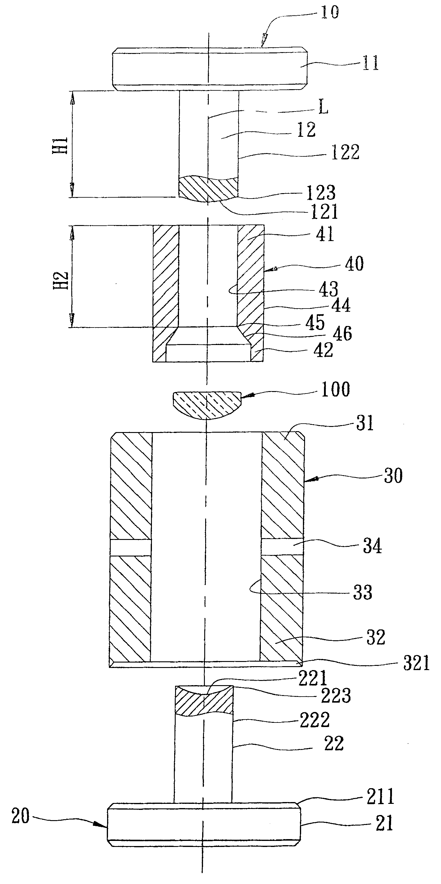
图2是本发明一较佳实施例的平面分解图;Figure 2 is a plane exploded view of a preferred embodiment of the present invention;
图3是本发明上述较佳实施例的平面组合示意图;Fig. 3 is the plan combination schematic diagram of above-mentioned preferred embodiment of the present invention;
图4是本发明上述较佳实施例的操作示意图,说明一第一模仁沿一轴线相对于一第二模仁产生靠合且使一硝材被挤压;Fig. 4 is a schematic diagram of the operation of the above-mentioned preferred embodiment of the present invention, illustrating that a first mold core is abutted against a second mold core along an axis and a nitrate material is squeezed;
图5是本发明上述较佳实施例的芯取完成示意图,说明该第一模仁继续相对于第二模仁产生靠合且一芯取件沿轴线位移而将一余料切除。Fig. 5 is a schematic diagram of the completion of core taking in the above-mentioned preferred embodiment of the present invention, illustrating that the first mold core continues to abut against the second mold core and a core member is displaced along the axis to remove a surplus material.
具体实施方式 Detailed ways
如图2所示,本发明可同步芯取的精密玻璃模造成形装置较佳实施例,包含一第一模仁10、一与该第一模仁10相对设置的第二模仁20、一套设在该第一、二模仁10、20外部的定位件30及一套设在该定位件30与该第一、二模仁10、20之间的芯取件40。As shown in Figure 2, a preferred embodiment of the precision glass molding device capable of synchronous core taking in the present invention includes a
该第一模仁10是制成阶级柱状,并具有一第一盘部11及一沿一轴线L由该第一盘部11一底面凸设的第一模杆12,该第一模杆12的圆径与玻璃成品的外径相同,并具有一设于一底面的第一塑形面121、一由该第一塑形面121周缘沿该轴线L朝该第一盘部11延伸的第一外周面122及一设置在该第一塑形面121与该第一外周面122衔接处的第一端缘123。该第一盘部11一底面与该第一端缘123之间具有一第一距离H1。The
该第二模仁20是沿该轴线L设置在该第一模仁10下方,也是制成阶级柱状,并具有一第二盘部21及一沿该轴线L由该第二盘部21一顶面凸设的第二模杆22。该第二盘部21具有一设于顶周缘且呈由上朝下倾斜设置的导正部211,该第二模杆22的圆径也与玻璃成品的外径相同,并具有一与该第一模仁10的第一塑形面121呈相对的第二塑形面221、一由该第二塑形面221周缘沿该轴线L朝该第二盘部21延伸的第二外周面222及一设置在该第二塑形面221与该第二外周面222衔接处的第二端缘223。The
该定位件30是制成中空筒状,且与该第一、二模仁10、20同心设置而套设在该第一、二模仁10、20外部,并具有一对应该第一盘部11的顶端部31、一可嵌套定位在该第二盘部21上的底端部32、一与该第一、二外周面122、222相对设置且由该顶端部31延伸至该底端部32的内周面33及多数个设于该顶、底端部31、32之间的排气孔34。该底端部32凹设有一与该导正部211互相嵌套的套合部321。The
该芯取件40是制成中空筒状且套设在该定位件30与该第一、二模仁10、20之间,并具有一对应该第一盘部11的压制端部41、一与该压制端部41呈相反设置的操作端部42、一由该压制端部41延伸至该操作端部42且相对于该第一、二外周面122、222的内环面43、一与该内环面43相背设置且可沿该内周面33滑动的外环面44、一设于该操作端部42且位在该内环面43侧端的刃缘45及一设于该刃缘45外侧且呈锥面状的限位部46,该限位部46是由该刃缘45逐渐向下倾斜扩张。该压制端部41一顶面与该刃缘45之间具有一第二距离H2,该第二距离H2小于该第一距离H1。The
本发明的成形装置是设置在一具有加热单元的环境中(可实施例的方式很多,且并非本发明的申请标的,所以图未示),且如图3所示,当欲模造玻璃时,是先将一具有预定形体且为定量的硝材100放置在该第一、二模仁10、20的第一、二塑形面121、221之间,且使该芯取件40的刃缘45位在一预备位置,也就是该刃缘45对应于该第一端缘123,而该限位部46跨骑在该硝材100顶部周缘,且该第一盘部11与该压制端部41之间具有一第一间隙h1,该第一盘部11与该顶端部31之间具有一第二间隙h2。The forming device of the present invention is arranged in an environment with a heating unit (there are many ways to implement, and it is not the application target of the present invention, so the figure is not shown), and as shown in Figure 3, when the glass is to be molded, Firstly, a predetermined shape and
再如图4所示,当该硝材100加热至一成型温度产生软化后,可驱动该第一模仁10沿该轴线L朝该第二模仁20相对靠合以进行预合模,该第一模仁10下移,使该第一盘部11抵触该芯取件40的压制端部41,致使图3的第一间隙h1消失,接着,该第一模仁10与芯取件40再一起略为下移,使图3的第二间隙h2缩小为一第三间隙h3,并使该硝材100被挤压而产生一凸伸在该第一、二外周面122、222外部的余料110,此时,利用该第二距离H2小于该第一距离H1的作用,该芯取件40的刃缘45位在一尚未越过该第一端缘123的第一位置,且该刃缘45尚未对该余料110产生作用。As shown in Figure 4 again, when the
又如图5所示,当将该第一模仁10沿该轴线L继续朝该第二模仁20产生靠合,使图4的第三间隙h3再缩小,且使该硝材100的温度在一软化温度以上并到达一中心厚度的同时,该芯取件40会沿轴线L产生位移,且使该刃缘45可由尚未越过该第一端缘123的第一位置,越过该第二模仁20的第二端缘223而位移至一第二位置,且使余料110被切除而随该芯取件40向下掉落,而使一雏形体留滞在该第一、二模仁10、20之间。As shown in Figure 5 again, when the
当第一、二塑形面121、221之间的雏形体已降至一玻璃转换温度以下且定型成一玻璃成品100’时,再取出该第一模仁10、玻璃成品100’、芯取件40等,以利于下一次模造作业的进行。When the prototype body between the first and
且切除后的余料110会滞留在该定位件30与该第二模仁20之间,当模造数次后,再进行余料的清理。And the
因此,本发明利用上述的成形装置,可免除如现有的车磨芯取制程,且具有下列优点:Therefore, the present invention utilizes the above-mentioned forming device, which can avoid the existing turning and grinding core-taking process, and has the following advantages:
一、对硝材100进行模造及芯取成玻璃成品100’的过程,都是在该成型装置中进行,所以玻璃成品100不会有被夹持治具夹持的问题,也可改善因夹持所造成的偏心过大、玻璃会产生较大误差的问题、影响镀膜良率...等问题。1. The process of molding the
二、因为没有车磨的后工程,也没有被夹持治具夹伤的问题,可提高良率。2. Because there is no post-engineering of turning and grinding, and there is no problem of being pinched by the clamping fixture, the yield rate can be improved.
三、因为不需要以治具夹持进行车磨,所以可省略上油、去油、抛光...等制程,可提高产能及降低成本。3. Because there is no need to use jigs for grinding, oiling, degreasing, polishing, and other processes can be omitted, which can increase production capacity and reduce costs.
四、因为没有车磨的后工程,所以也可省却夹持治具、研磨轮等的设置,可降低成本。4. Because there is no post-engineering of turning and grinding, the setting of clamping fixtures and grinding wheels can also be saved, which can reduce costs.
五、直接在该成形装置上设置该芯取件40,且在该硝材100芯取成玻璃成品100’的过程,是以一贯且连续的动作进行,不但简化制作流程、节省工时,且也可提升产能及品质。5. The
Claims (4)
Priority Applications (1)
| Application Number | Priority Date | Filing Date | Title |
|---|---|---|---|
| CNB2005100807914A CN100540489C (en) | 2005-07-05 | 2005-07-05 | Precision glass molding forming device capable of synchronously coring |
Applications Claiming Priority (1)
| Application Number | Priority Date | Filing Date | Title |
|---|---|---|---|
| CNB2005100807914A CN100540489C (en) | 2005-07-05 | 2005-07-05 | Precision glass molding forming device capable of synchronously coring |
Publications (2)
| Publication Number | Publication Date |
|---|---|
| CN1891644A CN1891644A (en) | 2007-01-10 |
| CN100540489C true CN100540489C (en) | 2009-09-16 |
Family
ID=37596878
Family Applications (1)
| Application Number | Title | Priority Date | Filing Date |
|---|---|---|---|
| CNB2005100807914A Expired - Fee Related CN100540489C (en) | 2005-07-05 | 2005-07-05 | Precision glass molding forming device capable of synchronously coring |
Country Status (1)
| Country | Link |
|---|---|
| CN (1) | CN100540489C (en) |
Citations (5)
| Publication number | Priority date | Publication date | Assignee | Title |
|---|---|---|---|---|
| CN1096739A (en) * | 1994-04-14 | 1994-12-28 | 陈钦仁 | Mold manufacturing method for single lens double focal length lens |
| CN1139043A (en) * | 1995-06-27 | 1997-01-01 | 程杰 | Mould pressing and cutting process for forming monocamber of contact lens |
| CN1166153A (en) * | 1995-10-24 | 1997-11-26 | 旭光学株式会社 | Mold for molding a resin lens and resin lens produced by using the same mold |
| EP1108688A1 (en) * | 1999-04-22 | 2001-06-20 | Matsushita Electric Industrial Co., Ltd. | Method and apparatus for molding optical device |
| US20050132751A1 (en) * | 2003-12-23 | 2005-06-23 | Asia Optical Co., Inc. | Method for making a precision molding glass and molding device implementing for the method |
-
2005
- 2005-07-05 CN CNB2005100807914A patent/CN100540489C/en not_active Expired - Fee Related
Patent Citations (5)
| Publication number | Priority date | Publication date | Assignee | Title |
|---|---|---|---|---|
| CN1096739A (en) * | 1994-04-14 | 1994-12-28 | 陈钦仁 | Mold manufacturing method for single lens double focal length lens |
| CN1139043A (en) * | 1995-06-27 | 1997-01-01 | 程杰 | Mould pressing and cutting process for forming monocamber of contact lens |
| CN1166153A (en) * | 1995-10-24 | 1997-11-26 | 旭光学株式会社 | Mold for molding a resin lens and resin lens produced by using the same mold |
| EP1108688A1 (en) * | 1999-04-22 | 2001-06-20 | Matsushita Electric Industrial Co., Ltd. | Method and apparatus for molding optical device |
| US20050132751A1 (en) * | 2003-12-23 | 2005-06-23 | Asia Optical Co., Inc. | Method for making a precision molding glass and molding device implementing for the method |
Also Published As
| Publication number | Publication date |
|---|---|
| CN1891644A (en) | 2007-01-10 |
Similar Documents
| Publication | Publication Date | Title |
|---|---|---|
| CN102139465B (en) | High-efficiency ultra-precision machining method for parts with aspheric curved surfaces and high-efficiency ultra-precision machining device therefor | |
| CN104310755B (en) | A kind of chalcogenide glass non-spherical lens manufacturing process | |
| CN106830631B (en) | Forming method for precision mould pressing edge-grinding-free chalcogenide glass lens | |
| CN100540489C (en) | Precision glass molding forming device capable of synchronously coring | |
| CN103158079A (en) | Processing device for air bag polishing tool surface polishing pad | |
| CN106132884B (en) | Die set for molding optical element and manufacturing method of optical element | |
| WO2015124010A1 (en) | Glass mold cavity polishing apparatus | |
| CN100371272C (en) | Method for manufacturing molded optical element | |
| TWI277610B (en) | Precision glass molding device capable of core removing | |
| CN101450835A (en) | Mold making apparatus and compression molding forming method | |
| JP5559982B2 (en) | Glass aspheric lens and manufacturing method thereof | |
| JPS6051623A (en) | Process for molding optical element | |
| JP5649928B2 (en) | Optical element molding die, optical element molding method, and optical element molding die manufacturing method | |
| TWI290542B (en) | Glass mold forming device, apparatus and method | |
| CN110549586A (en) | Lens molding method, lens mold and lens | |
| CN205237854U (en) | Be applied to novel mould of spherical radome fairing convex surface luster -finish of high accuracy | |
| TWI232207B (en) | Core removal method for precision glass molding and molding device | |
| JP3869507B2 (en) | Method for forming optical glass element | |
| CN111231200A (en) | Mould pressing mould core of optical plastic lens and manufacturing method of mould pressing mould core | |
| CN108472832B (en) | Method for manufacturing mold for rubber article and mold for rubber article | |
| US1534671A (en) | Method of producing finished surfaces upon glass | |
| CN1319884C (en) | Core taking method for precision molded glass | |
| CN102841400A (en) | Manufacturing method for light guide plate | |
| JP2001261350A (en) | Method of producing optical element and mold for forming used for production thereof | |
| CN110549259A (en) | A small-size hot-pressed resin diamond grinding head tooling, grinding head, and grinding tool manufacturing method |
Legal Events
| Date | Code | Title | Description |
|---|---|---|---|
| C06 | Publication | ||
| PB01 | Publication | ||
| C10 | Entry into substantive examination | ||
| SE01 | Entry into force of request for substantive examination | ||
| C14 | Grant of patent or utility model | ||
| GR01 | Patent grant | ||
| CF01 | Termination of patent right due to non-payment of annual fee |
Granted publication date: 20090916 Termination date: 20140705 |
|
| EXPY | Termination of patent right or utility model |