CN100540373C - Pneumatic booster - Google Patents
Pneumatic booster Download PDFInfo
- Publication number
- CN100540373C CN100540373C CNB2004100565639A CN200410056563A CN100540373C CN 100540373 C CN100540373 C CN 100540373C CN B2004100565639 A CNB2004100565639 A CN B2004100565639A CN 200410056563 A CN200410056563 A CN 200410056563A CN 100540373 C CN100540373 C CN 100540373C
- Authority
- CN
- China
- Prior art keywords
- elastic member
- plunger
- mentioned
- reaction
- pressure
- Prior art date
- Legal status (The legal status is an assumption and is not a legal conclusion. Google has not performed a legal analysis and makes no representation as to the accuracy of the status listed.)
- Expired - Fee Related
Links
Images


Classifications
-
- B—PERFORMING OPERATIONS; TRANSPORTING
- B60—VEHICLES IN GENERAL
- B60T—VEHICLE BRAKE CONTROL SYSTEMS OR PARTS THEREOF; BRAKE CONTROL SYSTEMS OR PARTS THEREOF, IN GENERAL; ARRANGEMENT OF BRAKING ELEMENTS ON VEHICLES IN GENERAL; PORTABLE DEVICES FOR PREVENTING UNWANTED MOVEMENT OF VEHICLES; VEHICLE MODIFICATIONS TO FACILITATE COOLING OF BRAKES
- B60T13/00—Transmitting braking action from initiating means to ultimate brake actuator with power assistance or drive; Brake systems incorporating such transmitting means, e.g. air-pressure brake systems
- B60T13/10—Transmitting braking action from initiating means to ultimate brake actuator with power assistance or drive; Brake systems incorporating such transmitting means, e.g. air-pressure brake systems with fluid assistance, drive, or release
- B60T13/24—Transmitting braking action from initiating means to ultimate brake actuator with power assistance or drive; Brake systems incorporating such transmitting means, e.g. air-pressure brake systems with fluid assistance, drive, or release the fluid being gaseous
- B60T13/46—Vacuum systems
- B60T13/52—Vacuum systems indirect, i.e. vacuum booster units
- B60T13/57—Vacuum systems indirect, i.e. vacuum booster units characterised by constructional features of control valves
-
- B—PERFORMING OPERATIONS; TRANSPORTING
- B60—VEHICLES IN GENERAL
- B60T—VEHICLE BRAKE CONTROL SYSTEMS OR PARTS THEREOF; BRAKE CONTROL SYSTEMS OR PARTS THEREOF, IN GENERAL; ARRANGEMENT OF BRAKING ELEMENTS ON VEHICLES IN GENERAL; PORTABLE DEVICES FOR PREVENTING UNWANTED MOVEMENT OF VEHICLES; VEHICLE MODIFICATIONS TO FACILITATE COOLING OF BRAKES
- B60T13/00—Transmitting braking action from initiating means to ultimate brake actuator with power assistance or drive; Brake systems incorporating such transmitting means, e.g. air-pressure brake systems
- B60T13/10—Transmitting braking action from initiating means to ultimate brake actuator with power assistance or drive; Brake systems incorporating such transmitting means, e.g. air-pressure brake systems with fluid assistance, drive, or release
- B60T13/24—Transmitting braking action from initiating means to ultimate brake actuator with power assistance or drive; Brake systems incorporating such transmitting means, e.g. air-pressure brake systems with fluid assistance, drive, or release the fluid being gaseous
- B60T13/46—Vacuum systems
- B60T13/52—Vacuum systems indirect, i.e. vacuum booster units
- B60T13/573—Vacuum systems indirect, i.e. vacuum booster units characterised by reaction devices
- B60T13/575—Vacuum systems indirect, i.e. vacuum booster units characterised by reaction devices using resilient discs or pads
Landscapes
- Engineering & Computer Science (AREA)
- Transportation (AREA)
- Mechanical Engineering (AREA)
- Braking Systems And Boosters (AREA)
Abstract
一种气压式增力装置。其在紧急制动时迅速提升伺服力确保必要的制动力。在分隔成等压室(4A、5A)和变压室(4B、5B)的动力活塞(6、7)上连接阀体(10)。在反作用部件(12)和柱塞(15)之间安装弹性部件(31)。移动柱塞(15),打开提动阀座(16),向变压室(4B、5B)内导入大气,使之和等压室(4A、5A)之间产生差压,由该差压赋予输出杆(13)伺服力,输出杆(13)的反作用力的一部分通过反作用盘(12)反馈在输入杆(17)上。在紧急制动时,销(39)推动活塞(32)后退,弹性部件(31)被压入活塞(32)的外周槽(42)内而在轴方向被压缩,因而能够不受反作用力而增大柱塞(15)的移动量,能够迅速地提升伺服力。
A pneumatic booster device. It quickly increases the servo force to ensure the necessary braking force during emergency braking. A valve body (10) is connected to a power piston (6, 7) divided into an equal pressure chamber (4A, 5A) and a variable pressure chamber (4B, 5B). An elastic member (31) is installed between the reaction member (12) and the plunger (15). Move the plunger (15), open the poppet valve seat (16), and introduce the atmosphere into the variable pressure chamber (4B, 5B), so that a differential pressure is generated between it and the equal pressure chamber (4A, 5A). A servo force is given to the output rod (13), and a part of the reaction force of the output rod (13) is fed back on the input rod (17) through the reaction disc (12). During emergency braking, the pin (39) pushes the piston (32) back, and the elastic member (31) is pressed into the outer peripheral groove (42) of the piston (32) and compressed in the axial direction, so it can be By increasing the movement amount of the plunger (15), the servo force can be rapidly increased.
Description
技术领域 technical field
本发明涉及安装在汽车等车的制动器上的气压式增力装置。The present invention relates to a pneumatic booster installed on the brakes of automobiles and the like.
背景技术 Background technique
一般,在汽车的制动器上,为了提高制动力安装气压式增力装置。众所周知,气压式增力装置由动力活塞把壳体内部分隔成等压室(通过发动机吸气负压,通常保持为负压)和变压室,阀体连接在动力活塞上,由输入杆使设置在阀体内的柱塞移动而向变压室内导入大气(正压),这样,使等压室和变压室之间产生压力差,由该压力差在动力活塞上产生的推力通过反作用部件作用在输出杆上,同时从输出杆作用在反作用部件的反作用力的一部分反馈在输入杆上。Generally, a pneumatic booster is installed on the brakes of an automobile in order to increase the braking force. As we all know, the pneumatic booster device is divided into an equal pressure chamber (through the engine suction negative pressure, usually maintained as negative pressure) and a pressure change chamber by the power piston. The valve body is connected to the power piston, and the input rod drives The plunger set in the valve body moves to introduce atmospheric air (positive pressure) into the pressure change chamber, so that a pressure difference is generated between the equal pressure chamber and the pressure change chamber, and the thrust generated by the pressure difference on the power piston passes through the reaction component Acts on the output rod, and at the same time part of the reaction force acting on the reaction member from the output rod is fed back on the input rod.
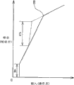
这种气压式增力装置的输入(制动踏板的踏力)和输出(制动力)的关系如图8中的实线所示,在制动初期阶段通过柱塞和反作用部件之间的间隙产生跃变输出A,然后,输出与输入成正比增加达到全负荷点B。The relationship between the input (depression force of the brake pedal) and the output (braking force) of this pneumatic booster device is shown by the solid line in Figure 8, which is generated by the gap between the plunger and the reaction component at the initial stage of braking. Jump output A, then, the output increases in proportion to the input to full load point B.
然而,如上述现有的气压式增力装置的制动踏板的踏力和制动力成正比例增加的特性,在紧急情况为产生大的制动力时,当然需要大的踏力。因此,希望有一种在紧急情况需要大的制动力时应该能减轻制动踏板的踏力的带制动增力装置的气压式增力装置。具有制动增力装置的气压式增力装置和防止制动时抱死车轮的防抱死制动装置相辅相成,能够期待大幅度提高紧急情况时的制动力。However, as in the above-mentioned conventional air booster, the pedal force of the brake pedal increases proportionally to the braking force, so in order to generate a large braking force in an emergency, a large pedaling force is naturally required. Therefore, it is desirable to have a pneumatic booster with a brake booster that should be able to reduce the pedaling effort of the brake pedal when a large braking force is required in an emergency. Combining the pneumatic booster with brake booster and the anti-lock brakes to prevent the wheels from locking during braking, it is possible to expect a significant increase in emergency braking force.
带制动增力装置的气压式增力装置,例如下述专利文献1中所述的众所周知的类型:通过使用由弹簧伸缩而移动的柱塞,当制动踏板踏力超过一定值这样的紧急情况时,由于弹簧被压缩,柱塞相对阀体大幅度地变位,如图8中的C部所示地增力比率急速增大,因而能够获得大制动力。Pneumatic booster with brake booster, such as the well-known type described in the following patent document 1: By using a plunger moved by expansion and contraction of a spring, when the brake pedal force exceeds a certain value in an emergency , since the spring is compressed, the plunger is greatly displaced relative to the valve body, and the boost ratio is rapidly increased as shown in part C in Fig. 8, so that a large braking force can be obtained.
[专利文献1]特开2000-25603号公报。[Patent Document 1] JP-A-2000-25603.
发明内容 Contents of the invention
本发明借鉴上述原理,目的是提供结构简单、在紧急情况时迅速提升输出压力、能够可靠地产生必要的制动力的气压式增力装置。The purpose of the present invention is to provide a pneumatic booster with a simple structure, which can quickly increase the output pressure in an emergency and can reliably generate the necessary braking force.
为了解决上述课题,本发明的气压式增力装置的结构是:由动力活塞把壳体内部分隔成等压室和变压室,阀体连接在上述动力活塞上,由输入杆推动配置在阀体内的柱塞移动而打开阀装置,把工作气体导入上述变压室内,使上述等压室和变压室之间产生压力差,由该压力差在动力活塞上产生的推力通过反作用部件作用在输出杆上,同时把该输出杆作用在上述反作用部件的反作用力的一部分传递到上述输入杆上。该气压式增力装置还设置了下述的控制装置:在上述反作用部件和上述柱塞之间插入安装环形弹性部件,通常,通过限制上述弹性部件的向径方向内侧的变形,限制上述弹性部件的上述柱塞移动方向的尺寸被压缩;当上述柱塞对上述阀体的移动量达到规定值时,通过容许上述弹性部件向径方向内侧变形,容许上述弹性部件的上述柱塞移动方向的尺寸被压缩。In order to solve the above-mentioned problems, the structure of the pneumatic booster device of the present invention is that the inside of the housing is divided into an equal pressure chamber and a variable pressure chamber by a power piston. The plunger in the body moves to open the valve device, and the working gas is introduced into the above-mentioned pressure-transforming chamber, so that a pressure difference is generated between the above-mentioned equal-pressure chamber and the pressure-transforming chamber, and the thrust generated by the pressure difference on the power piston acts on the On the output rod, at the same time, a part of the reaction force of the output rod acting on the above-mentioned reaction member is transmitted to the above-mentioned input rod. The pneumatic booster is also provided with the following control device: an annular elastic member is inserted and installed between the above-mentioned reaction member and the above-mentioned plunger, and generally, by restricting the deformation of the above-mentioned elastic member to the inside in the radial direction, the elastic member is restricted. The size of the above-mentioned plunger moving direction is compressed; when the moving amount of the above-mentioned plunger to the above-mentioned valve body reaches a predetermined value, by allowing the above-mentioned elastic member to deform inward in the radial direction, the size of the above-mentioned plunger moving direction of the above-mentioned elastic member is allowed is compressed.
通过这样的结构,当向输入杆的输入速度快时,柱塞对阀体的移动量增大,控制装置容许弹性部件向径方向内侧的变形,弹性体在柱塞的移动方向被压缩,因而不增大反作用部件的反作用力,就能够增大柱塞的移动量,能够增大阀装置的开度而增大向输出杆的输出,这样,在紧急制动时,能够减轻操作力同时迅速地提升制动力。With such a structure, when the input speed to the input rod is fast, the movement amount of the plunger to the valve body increases, the control device allows the elastic member to deform inward in the radial direction, and the elastic body is compressed in the direction of movement of the plunger, thus Without increasing the reaction force of the reaction member, the movement amount of the plunger can be increased, the opening of the valve device can be increased, and the output to the output rod can be increased. In this way, the operating force can be reduced and the operation speed can be quickly reduced during emergency braking. increase the braking force.
附图说明 Description of drawings
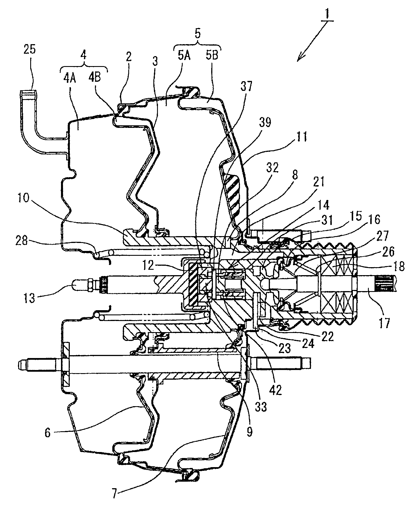
图1是涉及本发明的一实施方式的气压式增力装置的纵剖面图;FIG. 1 is a longitudinal sectional view of a pneumatic booster according to an embodiment of the present invention;
图2是放大表示图1的装置的主要部分的图;Fig. 2 is the figure that enlarges and represents the main part of the device of Fig. 1;
图3是放大表示图1的装置的主要部分的横剖面图;Fig. 3 is an enlarged cross-sectional view showing the main part of the device of Fig. 1;
图4是表示图1的装置中普通的制动状态的图;Fig. 4 is a diagram representing a common braking state in the device of Fig. 1;
图5表示在图1的装置中紧急制动时销触接受压部件的后端部的状态的图;Fig. 5 represents the figure of the state that pin touches the rear end portion of pressure-receiving part when emergency braking in the device of Fig. 1;
图6表示在图1的装置中紧急制动时压缩弹性部件后,保持着制动力的状态的图;Fig. 6 represents the diagram of the state of keeping the braking force after compressing the elastic member during emergency braking in the device of Fig. 1;
图7表示图1所示的装置的输入和输出的关系的曲线图;Figure 7 is a graph showing the relationship between the input and output of the device shown in Figure 1;
图8表示具有现在的制动增力装置的气压式增力装置的输入和输出的关系的曲线图。FIG. 8 is a graph showing the relationship between the input and the output of the pneumatic booster having the conventional brake booster.
符号说明Symbol Description
1.气压式增力装置;2.壳体(外壳); 4A、5A.等压室;1. Pneumatic booster device; 2. Shell (shell); 4A, 5A. Isobaric chamber;
4B、5B.变压室; 6、7.动力活塞;10.阀体;4B, 5B. Transformer chamber; 6, 7. Power piston; 10. Valve body;
13.输出杆; 15.柱塞; 16.提动阀座(阀装置);13. Output rod; 15. Plunger; 16. Poppet valve seat (valve device);
17.输入杆; 31.弹性部件; 32.活塞(控制部件)17. Input rod; 31. Elastic part; 32. Piston (control part)
具体实施方式 Detailed ways
以下,按照附图详细说明本发明的一实施方式。Hereinafter, an embodiment of the present invention will be described in detail with reference to the drawings.
如图1所示,涉及本实施方式的气压式增力装置1是串联气压式增力装置,壳体2(外壳)的内部由隔壁3分隔成前室4和后室5两个室。前室4和后室5分别由动力活塞6、7分隔成等压室4A、5A和变压室4B、5B。在等压室4A、5A间以及变压室4B、5B间分别由通路8、9连通。大体圆筒形的阀体10连接在动力活塞6、7上;阀体10能够滑动并且气体密封地穿过外壳2的隔壁3和后壁11,阀体10的后端部从后壁11向外部延伸。在阀体10的前部介由反作用盘12(反作用部件)连接输出杆13,输出杆13的前端部连接在安装在壳体2的前壁上的主缸(没作图示)的活塞上。As shown in FIG. 1 , the
在阀体10内设置制动增力装置14、柱塞15、提动阀座16(阀装置)和输入杆17。在柱塞15的一端和反作用盘12之间安装制动增力装置14,在柱塞15的另一端上连接输入杆17的一端。输入杆17的另一端穿过安装在阀体10的后端部的透气性防尘密封18并向外部延伸,输入杆17的前端连接制动踏板(没作图示)。提动阀座16压接在阀体10的阀座19和塞柱15的阀座部20上,通过柱塞15的移动开闭连通等压室4A、5A的通路21和连通变压室4B、5B的通路22之间以及开闭通路22和大气之间。Inside the
在阀体10的通路22内插入定位键23,定位键23与壳体2的定位器24卡合而限定阀体10的后退位置以及柱塞15和阀体10的相对位置。另外,在图1和图2中,符号25表示连接在发动机的吸气管等负压源上、向等压室4A内导入负压的负压导入口,符号26表示输入杆17的回位弹簧,符号27表示推动提动阀座16的阀弹簧,符号28表示阀体10的回位弹簧。A
以下,参照图2和图3说明作为本实施方式的主要部分的即制动增力装置14。Hereinafter, the
制动增力装置14具有:触接反作用盘12的反作用部件29;触接柱塞15的夹套30;安装在反作用部件29和夹套30之间的环形弹性部件31;嵌装在反作用部件29、夹套30以及弹性部件31内的活塞32。反作用部件29由触接反作用盘12的小径的圆柱部33和触接弹性部件31的大径的圆筒部34组成,在圆筒部34的前端部侧壁上开设沿着径向贯通的销孔35。外圆部具有台阶36A的圆筒形的比率环36能够滑动地套嵌在圆柱部33上。比率环36通过在阀体10的前端部上安装的环形受压部37的台部36A卡合限定后退位置。销39穿通在反作用部件29的销孔35,从圆筒部34突出的销39的两端处于能够触接受压部件37的后端部的位置。销39比销孔35直径小,能够在销孔35内沿着反作用部件29的轴方向移动。The
夹套30由与反作用力部件29的圆筒部34的直径相同的圆筒部件40和固定在圆筒部件40的外侧的导向部件41组成,导向部件41套着反作用力部件29的圆筒部34且能够引导其滑动,在导向部件41的前端部形成的内折边部与在圆筒部34的后端部上形成的外折边部卡合,因而和反作用部件29连接。弹性部件31与反作用力部件29的圆筒部34和夹套30的圆筒部40直径相同,它们的内周内能够滑动地嵌装活塞32(控制部件)。在活塞32形成外周槽42。活塞32通过在和柱塞15之间设置的弹簧43推压销39。The
而且,在图2所示的非制动状态,在反作用盘12和反作用力部件29的圆柱部33之间设规定的跳跃间隙C,在销39和受压部件37的后端部之间也设置规定的间隙。另外,推压销39的活塞32的外周槽42配置在和反作用力部件29的圆筒部34相对的位置。And, in the non-braking state shown in FIG. Set the specified gap. In addition, the outer
以下说明上述结构的本实施方式的动作。The operation of this embodiment with the above configuration will be described below.
在图2所示的非制动状态,提动阀座16触压在阀座部19、20上,变压室4B、5B和大气和等压室4A、5A(负压)切断,等压室4A、5A和变压室4B、5B压力平衡,动力活塞上不产生推力。In the non-braking state shown in Figure 2, the
在踏制动踏板的速度低的平常的制动操作中,如图4所示,当通过输入杆17推动柱塞15向前移动时,阀座部20离开提动阀座16,变压室4B、5B中导入大气并与等压室4A、5A(负压)之间产生压力差。通过该压力差在动力活塞6、7上产生推力(伺服力),因而阀体10向前移动通过反作用盘12推压输出杆13。由于阀体10的向前移动提动阀座16落座在阀座部20上,于是停止大气导入,保持等压室4A、5A和变压室4B、5B的压力差。这时,由输出杆13作用在反作用盘12上的反作用力的一部分通过制动增力装置14反馈在柱塞15和输入杆17上。这样,就能够产生对应制动踏板踏力的伺服力。In a normal braking operation at which the speed of the brake pedal is low, as shown in Figure 4, when the
在制动增力装置14,由反作用盘12的反作用力形成的轴方向压缩力作用在弹性部件31上。因为弹性部件31被圆筒部34、圆筒部件40、导向部件41包围,处于密封空间内,向径向内侧和外侧的变形被限制,因其向轴向(柱塞15的移动方向)的压缩取决于其体积弹性,弹性系数很大,所以几乎没有被压缩。因而,来自反作用盘2的反作用力通过弹性部件按照原样传递到柱塞15侧。In the
在制动初期,通过跳跃间隙C,柱塞15能够不受反作用盘12的反作用力而向前移动,因而能够迅速提升制动力(跃变作用)。之后,来自反作用盘12的反作用力通过反作用力部件29的圆柱33和比率环36反馈在柱塞15和输入杆14上,而产生对应制动踏板踏力的制动力。因而,如图7中用实线P表示,向输入杆17的输入(制动踏力)和输出杆13的输出(制动力)的关系,在制动初期阶段产生跃变输出,然后,与输入成比例输出增大到达全负荷点。At the initial stage of braking, through the jump gap C, the
当解除向输入杆17的输入时,通过回位弹簧26,输入杆17和柱塞15后退,柱塞15的阀座部20推压提动阀座16离开阀座部19。这样,等压室4A、5A和变压室4B、5B连通,其之间的压力差解除,动力活塞6、7的推力消失,通过回位弹簧28的作用阀体10后退、制动被解除。When the input to the
当紧急制动时、即踏制动踏板的速度高时,如图5所示,由动力活塞6、7的推力推动阀体10移动的追随动作滞后子柱塞15的移动,销39触接在受压部件37的后端部上。这样,活塞32被销39推压向后移动,外周槽42向接触弹性部件31的位置移动。在该状态,如图6所示,在轴方向上被压缩的弹性部件31容许向径向内侧变形、被压入活塞32的外周槽42内,因而对轴向的压缩的弹性系数变得很小,制动增力装置14在轴方向被向柱塞15输入的压力和反作用盘12的反作用力压缩。这样,不会增大来自反作用盘12的反作用力没增大而能够使柱塞15向前移动,能够使阀座部20离开提动阀座16,能够向变压室4B、5B导入大气而产生大的伺服力。而且,比率环36的台阶部36A触接受压部件37的台阶部38之后,对于来自反作用盘12的反作用力的受压面积减少,增力比率增大。这样,在紧急情况时,制动增力装置14动作,容许弹性部件31向轴方向压缩,由此,如图7中虚线Q所示,能够减轻踏力,同时迅速地提升制动力。另外,由普通制动中变换为紧急制动时(在制动中加速踏制动踏板时),从此时变换为上述紧急制动时的动作,如图7中的箭头R所示,能够从制动中减轻踏力,迅速提升制动力。When emergency braking, that is, when the speed of stepping on the brake pedal is high, as shown in Figure 5, the thrust of the
Claims (2)
Applications Claiming Priority (3)
| Application Number | Priority Date | Filing Date | Title |
|---|---|---|---|
| JP328157/2003 | 2003-09-19 | ||
| JP328157/03 | 2003-09-19 | ||
| JP2003328157A JP4206877B2 (en) | 2003-09-19 | 2003-09-19 | Pneumatic booster |
Publications (2)
| Publication Number | Publication Date |
|---|---|
| CN1597404A CN1597404A (en) | 2005-03-23 |
| CN100540373C true CN100540373C (en) | 2009-09-16 |
Family
ID=34308811
Family Applications (1)
| Application Number | Title | Priority Date | Filing Date |
|---|---|---|---|
| CNB2004100565639A Expired - Fee Related CN100540373C (en) | 2003-09-19 | 2004-08-10 | Pneumatic booster |
Country Status (4)
| Country | Link |
|---|---|
| US (1) | US6978710B2 (en) |
| JP (1) | JP4206877B2 (en) |
| CN (1) | CN100540373C (en) |
| DE (1) | DE102004041613B4 (en) |
Families Citing this family (4)
| Publication number | Priority date | Publication date | Assignee | Title |
|---|---|---|---|---|
| DE102005036459A1 (en) * | 2005-08-03 | 2007-02-08 | Continental Teves Ag & Co. Ohg | Vacuum brake booster for hydraulic vehicle brake system, has recess running through control housing, and sealing unit sealing housing and tie rod, which projects through connecting channels and through hole of channel in radial side wall |
| DE102005054758A1 (en) * | 2005-11-17 | 2007-05-24 | Continental Teves Ag & Co. Ohg | Pneumatic brake booster of tandem type for e.g. hydraulic vehicle brake system, has booster casing, whereby connecting channels are formed in one or more separate components which are arranged in connection area of both casing half-shells |
| JP5692202B2 (en) * | 2012-11-08 | 2015-04-01 | トヨタ自動車株式会社 | Master cylinder and master cylinder device |
| CN103448706A (en) * | 2013-09-04 | 2013-12-18 | 浙江万向系统有限公司 | Vacuum booster assembly with BA valve |
Family Cites Families (4)
| Publication number | Priority date | Publication date | Assignee | Title |
|---|---|---|---|---|
| JP3396806B2 (en) * | 1999-03-31 | 2003-04-14 | トキコ株式会社 | Pneumatic booster |
| DE10019423B4 (en) * | 2000-04-19 | 2005-06-16 | Lucas Varity Gmbh | Vacuum brake booster with mechanical emergency brake assist |
| JP2002337681A (en) * | 2001-03-15 | 2002-11-27 | Bosch Automotive Systems Corp | Brake booster |
| JP2003095085A (en) * | 2001-09-25 | 2003-04-03 | Bosch Automotive Systems Corp | Brake booster |
-
2003
- 2003-09-19 JP JP2003328157A patent/JP4206877B2/en not_active Expired - Fee Related
-
2004
- 2004-07-28 US US10/900,688 patent/US6978710B2/en not_active Expired - Lifetime
- 2004-08-10 CN CNB2004100565639A patent/CN100540373C/en not_active Expired - Fee Related
- 2004-08-27 DE DE102004041613A patent/DE102004041613B4/en not_active Expired - Fee Related
Also Published As
| Publication number | Publication date |
|---|---|
| CN1597404A (en) | 2005-03-23 |
| DE102004041613B4 (en) | 2009-04-30 |
| JP4206877B2 (en) | 2009-01-14 |
| DE102004041613A1 (en) | 2005-04-14 |
| US20050061142A1 (en) | 2005-03-24 |
| US6978710B2 (en) | 2005-12-27 |
| JP2005088843A (en) | 2005-04-07 |
Similar Documents
| Publication | Publication Date | Title |
|---|---|---|
| US6564692B2 (en) | Brake booster | |
| KR100501955B1 (en) | Power braking devise with variable assistance ratio and reduced hysteresis | |
| US6711982B2 (en) | Brake booster | |
| CN100540373C (en) | Pneumatic booster | |
| CN101466581B (en) | Negative pressure booster | |
| US4287811A (en) | Brake booster | |
| CN100355608C (en) | Pneumatic Booster | |
| JPH0885442A (en) | Pneumatic booster | |
| US5038564A (en) | Pulsator-operated valving with reaction chamber accumulator for hydraulic booster system | |
| JPH0390465A (en) | pneumatic booster | |
| CN110962823B (en) | One-diaphragm device for double-diaphragm vacuum booster | |
| US6195994B1 (en) | Master cylinder with hydraulic reaction operating with developing pressure | |
| JPH10129458A (en) | Brake booster for vehicles | |
| JP4716100B2 (en) | Pneumatic booster | |
| JPH0858565A (en) | Pneumatic booster | |
| JP3661259B2 (en) | Booster | |
| JPH1148947A (en) | Negative pressure booster | |
| KR100916397B1 (en) | Brake booster for vehicle | |
| JPH0345457A (en) | fluid pressure booster | |
| WO2008044610A1 (en) | Negative pressure booster and brake booster using the same | |
| JPH0986398A (en) | Pneumatic booster | |
| JPS60104454A (en) | Brake booster | |
| JP2006273214A (en) | Pneumatic booster | |
| JPH0345458A (en) | fluid pressure booster | |
| KR20020009027A (en) | Return - spring of brake booster for car |
Legal Events
| Date | Code | Title | Description |
|---|---|---|---|
| C06 | Publication | ||
| PB01 | Publication | ||
| C10 | Entry into substantive examination | ||
| SE01 | Entry into force of request for substantive examination | ||
| C14 | Grant of patent or utility model | ||
| GR01 | Patent grant | ||
| CF01 | Termination of patent right due to non-payment of annual fee | ||
| CF01 | Termination of patent right due to non-payment of annual fee |
Granted publication date: 20090916 Termination date: 20210810 |