CN100537344C - Method and apparatus for controlling a bicycle transmission to compensate for power supply characteristics - Google Patents
Method and apparatus for controlling a bicycle transmission to compensate for power supply characteristics Download PDFInfo
- Publication number
- CN100537344C CN100537344C CNB2005101310928A CN200510131092A CN100537344C CN 100537344 C CN100537344 C CN 100537344C CN B2005101310928 A CNB2005101310928 A CN B2005101310928A CN 200510131092 A CN200510131092 A CN 200510131092A CN 100537344 C CN100537344 C CN 100537344C
- Authority
- CN
- China
- Prior art keywords
- signal
- bicycle
- secondary signal
- control unit
- power supply
- Prior art date
- Legal status (The legal status is an assumption and is not a legal conclusion. Google has not performed a legal analysis and makes no representation as to the accuracy of the status listed.)
- Expired - Fee Related
Links
Images


Classifications
-
- B—PERFORMING OPERATIONS; TRANSPORTING
- B62—LAND VEHICLES FOR TRAVELLING OTHERWISE THAN ON RAILS
- B62M—RIDER PROPULSION OF WHEELED VEHICLES OR SLEDGES; POWERED PROPULSION OF SLEDGES OR SINGLE-TRACK CYCLES; TRANSMISSIONS SPECIALLY ADAPTED FOR SUCH VEHICLES
- B62M25/00—Actuators for gearing speed-change mechanisms specially adapted for cycles
- B62M25/08—Actuators for gearing speed-change mechanisms specially adapted for cycles with electrical or fluid transmitting systems
Abstract
An apparatus for controlling a movable bicycle device comprises a power supply sensor that detects an abnormal power supply characteristic, and a control unit operatively coupled to the power supply sensor. The control unit provides a first signal to command the bicycle device to move in a first manner when the power supply has a first characteristic, and the control unit provides a second signal to command the bicycle device to move in a different second manner when the power supply has a second characteristic.
Description
Technical field
The present invention relates to bicycle, more particularly, the present invention relates to a kind of method and apparatus of the operation of bicycle drive that be used to control with compensate for power supply characteristics.
Background technology
Bicycle drive by electric motor operated is known recently.This driving device can be according to the speed of bicycle and self shifter, perhaps by cyclist's manual shift.Usually the manual input according to bicycle speed or cyclist produces shifting commands, and the transmission operating unit is controlled motor in response to shifting commands, and correspondingly sets the transmitting ratio of driving device.
For example, U.S. Patent No. 6162140 discloses a kind of change-speed box that comprises the motor driven of frame piece, movable piece and bindiny mechanism.Bindiny mechanism comprises the connector that links to each other with movable piece with frame piece, makes movable piece to move with respect to frame piece.Attaching parts one of pivotally is connected to by connection-connector in frame piece and the movable piece, and is provided with the motor that is used to make connection-connector rotation.Movable piece moves with respect to frame piece in response to the rotation of connection-connector.
U.S. Patent No. 5357177 discloses a kind of motorized adjustment device that is used for the electric chain transfer device of bicycle.This control apparatus comprises regulating part, is used for the actuating device of mobile regulating part, and the control unit that is used for accessory drive.Pre-set device and operationally be connected on the control unit, be used to store a plurality of setting values, wherein each setting value is corresponding to an operating position of regulating part and chain transfer device.Regulating part is moveable to desirable desired location, this desired location value is stored in to pre-set in the device then, so that replace previous desired location value, thereby sets up or accurately regulate the operating position of chain transfer device.
U.S. Patent No. 6740003 discloses a kind of device that is used for the bicycle speed-varying unit of electric control is moved to from first sprocket wheel second sprocket wheel.This device comprises the gear box position input end that is used for from the potentiometer received signal that is installed in the indicated gear box position on the change-speed box, be used to store the memory device of the benchmark gear box position of second sprocket wheel, and can provide a plurality of signals change-speed box is moved to the motion control circuit of second sprocket wheel from first sprocket wheel.Described a plurality of signal is included in first signal that change-speed box produces when removing at first from first sprocket wheel, and the secondary signal that produces during very near second sprocket wheel at change-speed box.Secondary signal can prevent that change-speed box from crossing second sprocket wheel.
In this known system, the speed of operating the motor of various locating elements depends on various power supply characteristics, for example voltage.For example, if by the high ambient temperature of wheel-type electric generator or high charge voltage and cause that power line voltage is higher than the design effort voltage of motor, the motor drive shaft that is used to operate change-speed box so may rotate than estimate faster.If the sampling rate of position transduser is not high enough, so change-speed box may directed overshoot sprocket wheel, and even can cause sprocket engagement outside chain and the target sprocket wheel.Like this, correctly control motor and can become very difficult, comprise that attempt is moved back into the tram with change-speed box.
Summary of the invention
The present invention relates to a kind of various features that are used to control the device of movable bicycle device.In one embodiment, the device that is used to control movable bicycle device comprises the power sensor that can detect improper power supply characteristic, and operationally is connected in the control unit on the power sensor.This control unit can provide first signal, move according to first mode when power supply has first characteristic with the order bicycle device, and this control unit can provide secondary signal, moves according to the second different modes when power supply has second characteristic with the order bicycle device.Wherein, the described bicycle device of described first signal command moves according to continuation mode, and the described bicycle device of secondary signal order moves according to intermittent mode.
The invention still further relates to a kind of method that is used to control movable bicycle device, comprise step: detect improper power supply characteristic; Provide first signal by control unit, to order described bicycle device when power supply has first characteristic, to move according to first mode, and provide secondary signal by control unit, move according to the second different modes when power supply has second characteristic to order described bicycle device.Wherein, the described bicycle device of described first signal command moves according to continuation mode, and the described bicycle device of secondary signal order moves according to intermittent mode.
Can know further feature of the present invention from following description, these features can be individually or are got up to form the basis of other invention with above-mentioned characteristics combination.
Description of drawings
Fig. 1 is the lateral plan of bicycle, wherein comprises a specific embodiment of the bicycle drive of electric control;
Fig. 2 is the detailed view of the specific embodiment that is installed in the parts on the handlebar of bicycle shown in Figure 1;
Fig. 3 is the block diagram of the specific embodiment of total motion control unit;
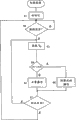
Fig. 4 is the diagram of circuit of specific embodiment that is used to control the algorithm of bicycle drive; With
Fig. 5 is the block diagram of another embodiment of total transmission control device.
The specific embodiment
Fig. 1 is the lateral plan of bicycle 1, wherein comprises a specific embodiment of the bicycle drive of electric control.In this embodiment, bicycle 1 is the sports type mountain bike, and it comprises vehicle frame 2, is installed in rotation on the front fork 3 on the vehicle frame 2, the handlebar 4 that is installed in front fork 3 tops, the front-wheel 5 that is rotatably connected to front fork 3 bottoms, the trailing wheel 6 that is rotatably connected to vehicle frame 2 rear portions, chain 7, preceding driving device 8, back driving device 9 and vehicle seat 11.Be provided with the rear-wheel brake 17 that is used for braking the front wheel brake 16 of front-wheel 5 and is used for braking rear-wheel 6.As shown in Figure 2, on the two ends of handlebar 4, be respectively equipped with handle 12a, 12b and restrictor bar 13a, 13b.Restrictor bar 13b is connected with front wheel brake 16 with braking front-wheel 5, and restrictor bar 13a is connected with braking rear-wheel 6 with rear-wheel brake 17.
Preceding driving device 8 is the mechanicals device that are connected the middle and lower part of vehicle frame 2, is used for propulsive effort driving device 9 after chain 7 passes to that the cyclist is produced.Before driving device 8 comprise three sprocket wheels 37 and the Front Derailleur 33 of different sizes.These three sprocket wheels 37 are installed on the driving crank 31, and when the cyclist was pedaled foot-operated 32a and 32b, this driving crank 31 just rotated.Driving crank 31 comprises that on even keel and rotary type ground pass through crank shaft 34, right crank 35 and the left crank 36 of vehicle frame 2 middle and lower parts.One end of right crank 35 is connected with the right side of crank shaft 34, and three sprocket wheels 37 are installed on the right crank 35.One end of left side crank 36 is connected with the left side of crank shaft 34.Other end of right crank 35 and left crank 36 has been supported foot-operated 32a and 32b respectively rotationally.Front Derailleur 33 makes an engagement in chain 7 and three sprocket wheels 37, and is moved by integral type Front Derailleur motor unit 50 (Fig. 3), and this unit 50 is by motion control unit 15 controls that are installed on the handlebar 4.All-in-one-piece Front Derailleur position transduser 52 detects the position of Front Derailleur 33, thus the position of detection and the current sprocket wheel 37 of chain 7 ingears.
Back driving device 9 is used for the propulsive effort that chain 7 is transmitted is passed to trailing wheel 6.Back driving device 9 comprises back chain wheel set 41 and Rear Derailleur 42.In this embodiment, back chain wheel set 41 comprises the sprocket wheel 43 of seven different sizes installing with one heart with the hub portion of trailing wheel 16.Rear Derailleur 42 makes an engagement in chain 7 and seven sprocket wheels 43, and moves by integral type Rear Derailleur motor unit 54 (referring to Fig. 3), and wherein this unit 54 is controlled by motion control unit 15.All-in-one-piece Rear Derailleur position transduser 56 detects the position of Rear Derailleur 42, thus the position of detection and the current sprocket wheel 43 of chain 7 ingears.
As shown in Figure 2, shifting commands unit 14a, 14b are separately positioned on the inboard of handle 12a, 12b and restrictor bar 13a, 13b.Motion control unit 15 is installed in the middle part of handle 4, and links to each other with shifting commands unit 14a, 14b.Shifting commands unit 14a, 14b are used for the gear of preceding driving device 8 of conversion manually and back driving device 9.In shifting commands unit 14a, be provided with back top gear button 18a and back bottom gear button 19a, top gear button 18b and preceding bottom gear button 19b before in shifting commands unit 14b, being provided with.In this embodiment, top gear button 18a and 18b can provide signal, so that heighten the gear of preceding driving device 8 and back driving device 9 by a sprocket wheel.Similarly, bottom gear button 19a and 19b can provide signal, so that turn down the gear of preceding driving device 8 and back driving device 9 by a sprocket wheel.
As shown in figs. 1 and 3, driving device 8 and back driving device 9 before motion control unit 15 is connected to by driver element 28.As shown in Figure 3, driver element 28 has held power supply 60 and power sensor 64.Power supply 60 offers Front Derailleur motor unit 50, Rear Derailleur motor unit 54 and/or motion control unit 15 with power for operation; Power sensor 64 detects the characteristic of power supply 60.In this embodiment, power sensor 64 comprises the voltage sensor of the voltage that can detect power supply 60.
Fig. 4 is the diagram of circuit of a specific embodiment of the algorithm of driving device 8 or control back driving device 9 before being used for controlling in the mode of the characteristic (as voltage) of offset supply 60.This algorithm activates when the cyclist connects the source switch 25 of motion control unit 15.
In step S1, carry out the initial setting up of motion control unit 15.Initial setting up generally includes resetting of mark and counting and other is handled, so that prepare for the normal operation of system.In step S2, determine whether then to receive from the gearshift request one of among shifting commands unit 14a or the shifting commands unit 14b.If do not receive, handle operation so and just get back to step S2.Otherwise, in step S3, from power sensor 64, obtain the current voltage V of power supply 60
PIn step S4, determine voltage V then
PWhether be higher than the predetermined voltage V that is stored in the memory device 22
HIn this embodiment, voltage V
HIt is the normal working voltage of corresponding Front Derailleur motor 50 or Rear Derailleur motor 54.Be higher than voltage V
HVoltage represent improper power supply characteristic.If power line voltage V
PBe not higher than voltage V
H, control unit 23 just provides the normal operation signal for Front Derailleur motor unit 50 or Rear Derailleur motor unit 54 so.For example, if control unit 23 direct control Front Derailleur motor unit 50 or Rear Derailleur motor units 54, the signal exported of control unit 23 can provide the aanalogvoltage that is enough to by normal mode operation Rear Derailleur motor unit 54 so.If Front Derailleur motor unit 50 or Rear Derailleur motor unit 54 comprise the control and treatment device of oneself, the signal that provided of control unit 23 can be a multistation digital signal so, and is as shown in table 1.
Table 1
| Function | Position 1 | |
| Clickwise | 0 | 1 |
| Left-hand revolution | 1 | 0 |
| Brake | 1 | 1 |
| Stop | 0 | 0 |
On the other hand, if in step S4, determine power line voltage V
PGreater than voltage V
H, so just detected improper power supply characteristic, handle operation and advance to step S6, and carry out the modified operation of Front Derailleur motor unit 50 or Rear Derailleur motor unit 54.In this embodiment, Front Derailleur motor unit 50 or Rear Derailleur motor unit 54 are operated according to intermittent mode.For example, if control unit 23 direct control Front Derailleur motor unit 50 or Rear Derailleur motor units 54, the signal exported of control unit 23 can provide batch (-type) (for example pulse wave or the square wave) aanalogvoltage that is enough to by step-by-step system operation Front Derailleur motor unit 50 so.If Front Derailleur motor unit 50 or Rear Derailleur motor unit 54 comprise the control and treatment device of oneself, the signal that provided of control unit 23 can be the alternation formula multistation digital signal of choosing from table 1 so.For example, control unit 23 can provide the dextrorotation rotaring signal, then is danger signal, is the dextrorotation rotaring signal then, is danger signal then, or the like.The distance that moves in given interval when in both cases, change-speed box is operated in step S6 is short during than operation in step S5.This has guaranteed that the slow sampling rate (with respect to the processing speed of control unit 23) of Front Derailleur position transduser 52 or Rear Derailleur position transduser 56 can not allow corresponding Front Derailleur motor unit 50 or Rear Derailleur motor unit 54 that Front Derailleur 33 or Rear Derailleur 42 are moved to beyond the target sprocket wheel.
In any case, in step S7, determine Front Derailleur position transduser 52 or whether Rear Derailleur position transduser 56 indicates corresponding Front Derailleur 33 or Rear Derailleur 42 has arrived required target sprocket wheel.If handle operation so and turn back to step S2.Otherwise, handle operation and turn back to step S3.
Though provided explanation above, can also adopt other modification and do not break away from the spirit and scope of the present invention to the various embodiment of inventive features.For example, Fig. 5 is the block diagram of another embodiment that adopts total motion control unit of distributed treatment notion.In this embodiment, Rear Derailleur control unit 23a with CPU21a and memory device 22a links to each other with back bottom gear button 19a with back top gear button 18a, so that utilize Rear Derailleur motor unit 54 and Rear Derailleur position transduser 56 to control Rear Derailleur 42.Independent Front Derailleur control unit 23b with CPU21b and memory device 22b links to each other with preceding bottom gear button 19b with preceding top gear button 18b, so that utilize Front Derailleur motor unit 50 and Front Derailleur position transduser 52 to control Front Derailleur 33.The operation of Rear Derailleur control unit 23a and/or Front Derailleur control unit 23b can be with described identical at control unit 23.This embodiment allows transmitting ratio that some changes are arranged, even also be like this during one of them control unit et out of order.
Claims (20)
1. device that is used to control movable bicycle device comprises:
Be used to detect the power sensor of improper power supply characteristic; With
Operationally be connected in the control unit on the described power sensor,
Wherein, described control unit can provide first signal, move according to first mode when power supply has first characteristic to order described bicycle device, and
Described control unit can provide secondary signal, moves according to the second different modes when power supply has second characteristic to order described bicycle device,
Wherein, the described bicycle device of described first signal command moves according to continuation mode, and the described bicycle device of secondary signal order moves according to intermittent mode.
2. device according to claim 1, it is characterized in that, the described bicycle device of first signal command is motion first distance in selected time gap, and the described bicycle device of secondary signal order different second distance of motion in described selected time gap.
3. device according to claim 1 is characterized in that first signal comprises the continous way signal, and secondary signal comprises batch mode signal.
4. device according to claim 1 is characterized in that, first signal comprises multidigit first digital signal, and secondary signal comprises multidigit second digital signal.
5. device according to claim 1, it is characterized in that, described device also comprises position transduser, it can provide the position indicative signal of the position of having indicated described bicycle device, described control unit operationally is connected on the described position transduser, and provides first signal and secondary signal based on described position indicative signal at least in part.
6. device according to claim 1 is characterized in that first signal and secondary signal are suitable for operating bicycle drive.
7. device according to claim 6 is characterized in that first signal and secondary signal are suitable for operating change-speed box.
8. device according to claim 6 is characterized in that, first signal and secondary signal are suitable for operating the motor that can make the bicycle drive motion.
9. device according to claim 1 is characterized in that, described improper power supply characteristic is corresponding to improper power line voltage.
10. device according to claim 9 is characterized in that described control unit provides first signal when power line voltage is lower than predetermined value, and described control unit provides secondary signal when power line voltage is higher than described predetermined value.
11. device according to claim 10, it is characterized in that, the described bicycle device of first signal command is motion first distance in selected time gap, and the described bicycle device of secondary signal order different second distance of motion in described selected time gap.
12. device according to claim 11 is characterized in that, described second distance is less than described first distance.
13. device according to claim 12 is characterized in that, first signal and secondary signal are suitable for operating bicycle drive.
14. device according to claim 13 is characterized in that, the described bicycle drive of first signal command moves according to continuation mode, and the described bicycle drive of secondary signal order moves according to intermittent mode.
15. device according to claim 14 is characterized in that, first signal comprises multidigit first digital signal, and secondary signal comprises multidigit second digital signal.
16. device according to claim 15 is characterized in that, first signal and secondary signal are suitable for operating change-speed box.
17. device according to claim 14 is characterized in that, first signal and secondary signal are suitable for operating the motor that can make described bicycle drive motion.
18. device according to claim 17 is characterized in that, first signal comprises the continous way signal, and secondary signal comprises batch mode signal.
19. device according to claim 18 is characterized in that, first signal and secondary signal are suitable for operating the motor that can make the change-speed box motion.
20. a method that is used to control movable bicycle device comprises step:
Detect improper power supply characteristic;
Provide first signal by control unit, when power supply has first characteristic, move according to first mode to order described bicycle device, and
Provide secondary signal by control unit, when power supply has second characteristic, move according to the second different modes to order described bicycle device,
Wherein, the described bicycle device of described first signal command moves according to continuation mode, and the described bicycle device of secondary signal order moves according to intermittent mode.
Applications Claiming Priority (2)
| Application Number | Priority Date | Filing Date | Title |
|---|---|---|---|
| US10/904,956 US7798929B2 (en) | 2004-12-07 | 2004-12-07 | Method and apparatus for controlling a bicycle transmission to compensate for power supply characteristics |
| US10/904956 | 2004-12-07 |
Publications (2)
| Publication Number | Publication Date |
|---|---|
| CN1785744A CN1785744A (en) | 2006-06-14 |
| CN100537344C true CN100537344C (en) | 2009-09-09 |
Family
ID=35457189
Family Applications (1)
| Application Number | Title | Priority Date | Filing Date |
|---|---|---|---|
| CNB2005101310928A Expired - Fee Related CN100537344C (en) | 2004-12-07 | 2005-12-07 | Method and apparatus for controlling a bicycle transmission to compensate for power supply characteristics |
Country Status (7)
| Country | Link |
|---|---|
| US (1) | US7798929B2 (en) |
| EP (1) | EP1669286B1 (en) |
| JP (1) | JP4235200B2 (en) |
| CN (1) | CN100537344C (en) |
| BR (1) | BRPI0505403A (en) |
| DE (1) | DE602005006946D1 (en) |
| TW (1) | TWI297754B (en) |
Families Citing this family (20)
| Publication number | Priority date | Publication date | Assignee | Title |
|---|---|---|---|---|
| US7704173B2 (en) * | 2006-02-08 | 2010-04-27 | Shimano Inc. | Motorized bicycle derailleur assembly |
| EP2103512B8 (en) * | 2008-01-24 | 2014-07-09 | Cycling Sports Group, Inc. | Bicycle user interface system and method of operation thereof |
| US20100010709A1 (en) * | 2008-01-24 | 2010-01-14 | Cannondale Bicycle Corporation | Bicycle distributed computing arrangement and method of operation |
| US10086708B2 (en) * | 2011-03-31 | 2018-10-02 | Shimano Inc. | Bicycle component control apparatus |
| US9284016B2 (en) * | 2011-03-31 | 2016-03-15 | Shimano Inc. | Bicycle component control apparatus |
| US20130145884A1 (en) * | 2011-12-07 | 2013-06-13 | Phong Nguyen | Unknown |
| ES2536323T3 (en) * | 2012-04-23 | 2015-05-22 | Campagnolo S.R.L. | Handlebar horn electric drive device for a bicycle gearshift |
| US9302739B2 (en) * | 2012-06-18 | 2016-04-05 | Shimano, Inc. | Bicycle power control apparatus |
| US9376345B2 (en) | 2013-06-25 | 2016-06-28 | Carboncure Technologies Inc. | Methods for delivery of carbon dioxide to a flowable concrete mix |
| JP2015027861A (en) * | 2013-07-05 | 2015-02-12 | 株式会社シマノ | Bicycle control system |
| JP2015140039A (en) * | 2014-01-27 | 2015-08-03 | 株式会社シマノ | Shift control device for bicycle |
| US9278728B1 (en) * | 2014-10-29 | 2016-03-08 | Shimano Inc. | Bicycle shifting control apparatus and method of controlling derailleur |
| US10363992B2 (en) * | 2015-01-29 | 2019-07-30 | Shimano Inc. | Electric bicycle component |
| US9944350B2 (en) * | 2016-01-11 | 2018-04-17 | Sram, Llc | Chain guide sensor and methods of controling a bicycle |
| US9714067B1 (en) * | 2016-02-29 | 2017-07-25 | Shimano Inc. | Bicycle chain device |
| TWI648198B (en) * | 2016-08-10 | 2019-01-21 | 天心工業股份有限公司 | Bicycle and its shifting device |
| US11072039B2 (en) * | 2018-06-13 | 2021-07-27 | General Electric Company | Systems and methods for additive manufacturing |
| US11414151B2 (en) | 2019-09-06 | 2022-08-16 | Shimano Inc. | Operating system for human-powered vehicle |
| DE102019214663A1 (en) * | 2019-09-25 | 2021-03-25 | Shimano Inc. | Bicycle derailleur system |
| TWI719705B (en) * | 2019-11-06 | 2021-02-21 | 天心工業股份有限公司 | Rear derailleur |
Citations (8)
| Publication number | Priority date | Publication date | Assignee | Title |
|---|---|---|---|---|
| US5357177A (en) * | 1992-04-13 | 1994-10-18 | Fichtel & Sachs Ag | Electrical adjustment device |
| CN1124705A (en) * | 1994-08-18 | 1996-06-19 | 本田技研工业株式会社 | Electric-power supplemented bicycle |
| CN1229940A (en) * | 1998-02-13 | 1999-09-29 | 株式会社岛野 | Gear position sensing unit |
| CN1270122A (en) * | 1999-02-16 | 2000-10-18 | 株式会社岛野 | Gear controller |
| CN1360386A (en) * | 2000-12-22 | 2002-07-24 | 株式会社岛野 | Circuit for drive control of motor-driven unit for moped |
| CN1417081A (en) * | 2001-11-09 | 2003-05-14 | 株式会社岛野 | Actuator assembly for motor-cycle |
| CN1488550A (en) * | 2002-08-29 | 2004-04-14 | 株式会社岛野 | Method and device for preventing bicycle transmission from incorrect gear-shift |
| US6740003B2 (en) * | 2002-05-02 | 2004-05-25 | Shimano, Inc. | Method and apparatus for controlling a bicycle transmission |
Family Cites Families (9)
| Publication number | Priority date | Publication date | Assignee | Title |
|---|---|---|---|---|
| US5213548A (en) * | 1992-03-02 | 1993-05-25 | Colbert Ralph G | Gear shifting system for derailleur equipped bicycle |
| DE4212319A1 (en) * | 1992-04-13 | 1993-10-14 | Fichtel & Sachs Ag | control device |
| US5261858A (en) * | 1992-06-19 | 1993-11-16 | Browning Automatic Transmission | Method and system for computer-controlled bicycle gear shifting |
| JP3727751B2 (en) | 1997-04-18 | 2005-12-14 | 株式会社三社電機製作所 | Bicycle transmission |
| US6162140A (en) | 1998-12-18 | 2000-12-19 | Shimano, Inc. | Motor driven derailleur |
| JP3242624B2 (en) * | 1999-04-12 | 2001-12-25 | 三菱電機株式会社 | DSRC OBE |
| US6945888B2 (en) | 2002-11-21 | 2005-09-20 | Shimano, Inc. | Combined analog and digital derailleur position processing apparatus |
| ATE521530T1 (en) | 2002-12-06 | 2011-09-15 | Campagnolo Srl | ELECTRONIC, SERVO OPERATED BICYCLE GEARSHIFT AND ASSOCIATED METHOD |
| EP1426284B1 (en) | 2002-12-06 | 2007-02-14 | Campagnolo Srl | Electronically servo-assisted bicycle gearshift and related method |
-
2004
- 2004-12-07 US US10/904,956 patent/US7798929B2/en not_active Expired - Fee Related
-
2005
- 2005-09-06 TW TW094130560A patent/TWI297754B/en active
- 2005-11-10 EP EP05024590A patent/EP1669286B1/en not_active Expired - Fee Related
- 2005-11-10 DE DE602005006946T patent/DE602005006946D1/en active Active
- 2005-11-22 JP JP2005336808A patent/JP4235200B2/en not_active Expired - Fee Related
- 2005-12-07 CN CNB2005101310928A patent/CN100537344C/en not_active Expired - Fee Related
- 2005-12-07 BR BRPI0505403-6A patent/BRPI0505403A/en not_active IP Right Cessation
Patent Citations (8)
| Publication number | Priority date | Publication date | Assignee | Title |
|---|---|---|---|---|
| US5357177A (en) * | 1992-04-13 | 1994-10-18 | Fichtel & Sachs Ag | Electrical adjustment device |
| CN1124705A (en) * | 1994-08-18 | 1996-06-19 | 本田技研工业株式会社 | Electric-power supplemented bicycle |
| CN1229940A (en) * | 1998-02-13 | 1999-09-29 | 株式会社岛野 | Gear position sensing unit |
| CN1270122A (en) * | 1999-02-16 | 2000-10-18 | 株式会社岛野 | Gear controller |
| CN1360386A (en) * | 2000-12-22 | 2002-07-24 | 株式会社岛野 | Circuit for drive control of motor-driven unit for moped |
| CN1417081A (en) * | 2001-11-09 | 2003-05-14 | 株式会社岛野 | Actuator assembly for motor-cycle |
| US6740003B2 (en) * | 2002-05-02 | 2004-05-25 | Shimano, Inc. | Method and apparatus for controlling a bicycle transmission |
| CN1488550A (en) * | 2002-08-29 | 2004-04-14 | 株式会社岛野 | Method and device for preventing bicycle transmission from incorrect gear-shift |
Also Published As
| Publication number | Publication date |
|---|---|
| BRPI0505403A (en) | 2006-09-12 |
| EP1669286B1 (en) | 2008-05-21 |
| EP1669286A3 (en) | 2006-11-15 |
| JP2006160247A (en) | 2006-06-22 |
| CN1785744A (en) | 2006-06-14 |
| US7798929B2 (en) | 2010-09-21 |
| US20060122015A1 (en) | 2006-06-08 |
| EP1669286A2 (en) | 2006-06-14 |
| DE602005006946D1 (en) | 2008-07-03 |
| TWI297754B (en) | 2008-06-11 |
| JP4235200B2 (en) | 2009-03-11 |
| TW200619533A (en) | 2006-06-16 |
Similar Documents
| Publication | Publication Date | Title |
|---|---|---|
| CN100537344C (en) | Method and apparatus for controlling a bicycle transmission to compensate for power supply characteristics | |
| CN101016076B (en) | Bicycle control arrangement and method | |
| CN100361865C (en) | Bicycle controller and method | |
| CN101513920B (en) | Bicycle component position correcting device | |
| CN106080871B (en) | Bicycle wireless control system | |
| EP1832504B1 (en) | Electronic derailleur control system | |
| US7062980B2 (en) | Bicycle shift control device with decreased stress during shifting | |
| CN105270557A (en) | Bicycle control device, motor assist bicycle, and motor control method | |
| JP4266986B2 (en) | Bicycle display device and bicycle control device | |
| CN1903654B (en) | Signal generating apparatus for a bicycle control device | |
| EP1338505B1 (en) | Method and apparatus for controlling a bicycle transmission | |
| EP2383178B1 (en) | Bicycle rear derailleur | |
| US7874567B2 (en) | Bicycle shifting control apparatus | |
| US7730803B2 (en) | Switch designation apparatus for a bicycle control unit | |
| CN106080937A (en) | Bicycle controller | |
| CN108016562A (en) | Bicycle control and the bicycle use control system for including it | |
| US10336400B2 (en) | Bicycle transmission control apparatus | |
| US6453262B1 (en) | Method and apparatus for selecting a processing mode for a bicycle computer | |
| US20220227458A1 (en) | Operating system for human-powered vehicle | |
| US11407473B2 (en) | Operating device and assist driving system for human-powered vehicle | |
| US11110992B2 (en) | Bicycle transmission control device | |
| EP1520777B1 (en) | Electronic control device for bicycle | |
| CN107792292A (en) | Bicycle and its speed change gear | |
| DE102020119820A1 (en) | ACTUATOR FOR A HUMAN POWERED VEHICLE | |
| JP2022182735A (en) | Control system for human-powered vehicle |
Legal Events
| Date | Code | Title | Description |
|---|---|---|---|
| C06 | Publication | ||
| PB01 | Publication | ||
| C10 | Entry into substantive examination | ||
| SE01 | Entry into force of request for substantive examination | ||
| C14 | Grant of patent or utility model | ||
| GR01 | Patent grant | ||
| CF01 | Termination of patent right due to non-payment of annual fee | ||
| CF01 | Termination of patent right due to non-payment of annual fee |
Granted publication date: 20090909 Termination date: 20191207 |