CN100537335C - Middle shaft structure with dynamo - Google Patents
Middle shaft structure with dynamo Download PDFInfo
- Publication number
- CN100537335C CN100537335C CNB2005100810739A CN200510081073A CN100537335C CN 100537335 C CN100537335 C CN 100537335C CN B2005100810739 A CNB2005100810739 A CN B2005100810739A CN 200510081073 A CN200510081073 A CN 200510081073A CN 100537335 C CN100537335 C CN 100537335C
- Authority
- CN
- China
- Prior art keywords
- axle
- electrical generator
- gear
- middle shaft
- shaft structure
- Prior art date
- Legal status (The legal status is an assumption and is not a legal conclusion. Google has not performed a legal analysis and makes no representation as to the accuracy of the status listed.)
- Expired - Fee Related
Links
Images


Classifications
-
- B—PERFORMING OPERATIONS; TRANSPORTING
- B62—LAND VEHICLES FOR TRAVELLING OTHERWISE THAN ON RAILS
- B62K—CYCLES; CYCLE FRAMES; CYCLE STEERING DEVICES; RIDER-OPERATED TERMINAL CONTROLS SPECIALLY ADAPTED FOR CYCLES; CYCLE AXLE SUSPENSIONS; CYCLE SIDE-CARS, FORECARS, OR THE LIKE
- B62K19/00—Cycle frames
- B62K19/30—Frame parts shaped to receive other cycle parts or accessories
- B62K19/34—Bottom brackets
-
- B—PERFORMING OPERATIONS; TRANSPORTING
- B62—LAND VEHICLES FOR TRAVELLING OTHERWISE THAN ON RAILS
- B62J—CYCLE SADDLES OR SEATS; AUXILIARY DEVICES OR ACCESSORIES SPECIALLY ADAPTED TO CYCLES AND NOT OTHERWISE PROVIDED FOR, e.g. ARTICLE CARRIERS OR CYCLE PROTECTORS
- B62J6/00—Arrangement of optical signalling or lighting devices on cycles; Mounting or supporting thereof; Circuits therefor
- B62J6/06—Arrangement of lighting dynamos or drives therefor
- B62J6/10—Gear drives
Abstract
The invention provides a bicycle middle shaft structure which is provided with a generator used for generating electricity when a rider rides the bicycle. The generator is provided with a static part fixed on the frame part of the bicycle and a rotary part which is connected with the frame part of the bicycle in a rotary way. The rotating part of the generator is connected with the shaft of the middle shaft structure of the bicycle through a planet gear unit optimally. Consequently, the planet gear unit is connected between the shaft and the rotary part of the generator so as to lead the rotary speed of the rotary part of the generator to be faster than that of the shaft.
Description
Technical field
The present invention relates generally to a kind of middle axle construction that has electrical generator or power facility.More specifically, the present invention relates to a kind of electrical generator or power facility that is installed on the bicycle middle shaft.
Background technology
Becoming a kind of entertainment form and transportation mode of increased popularity by bike.And, become a kind of all popular athletics sports campaign in amateur and professional athlete by bike.No matter bicycle use is in amusement, transportation or sports, bicycle industry all is more prone to by bike and enjoys so that make at the various assemblies of updating bicycle.
Recently, bicycle has been equipped with electric assembly so that be more prone to when making the cyclist by bike and enjoy.Sometimes, these bicycles have headlight, electric gear-change, electric derailleur or other electrical equipment.These electric installations need lasting supply of electrical energy usually.Some bicycles have the battery that is used to these electrical equipment supply electric energy.Yet the service life of battery is limited.Therefore, in order to prevent to use battery, many bicycles have the power facility that is used to these electrical equipment supply electric energy.These power facilities are installed on the front wheel hub usually so that be these electrical equipment supply electric power.These power facilities utilize the rotation generating of front-wheel, and electric power is delivered to electrical equipment (for example referring to Japanese publication publication No.2001-213104) by lead.Just work finely although power facility is placed in front wheel hub, when cyclist's coast, the existence of power facility may slow down the rotation of front-wheel.
Also propose electrical generator (power facility) to be installed in the axis of bicycle zone thus by the rotation of bicycle crank axle generate electricity (for example referring to Japanese publication publication No.55-141954).Yet power facility is installed on the axis and may slowly causes power shortage by bike the time the cyclist.
In view of above these aspects, by reading present disclosure, those skilled in the art should be understood that, just need a kind of improved type bicycle middle shaft structure.By reading present disclosure, those skilled in the art should be understood that the present invention can adapt to this requirement and other requirement of prior art.
Summary of the invention
An object of the present invention is to provide a kind of bicycle middle shaft structure that has power facility, it can produce the enough energy that is used to operate one or more electrical equipments.
Another object of the present invention provides the bicycle middle shaft structure, its manufacturing and assemble fairly simple and cost lower.
Another object of the present invention provides a kind of bicycle middle shaft structure of using planetary gear unit.
Above-mentioned purpose can comprise the bicycle middle shaft structure of axle, electrical generator and planetary gear unit and is achieved basically by providing a kind of.Axle has first end and second end.Electrical generator is installed on the axle, and has stationary part and rotating element.Planetary gear unit is connected between the axle and the rotating element of electrical generator so that make the rotating element of electrical generator rotate sooner than axle.
Concerning those skilled in the art,, can be well understood to these and other purpose of the present invention, feature, aspect and advantage by reading the following detailed description that discloses the preferred embodiments of the present invention in conjunction with the accompanying drawings.
Description of drawings
See also accompanying drawing now, it has constituted the part of the original disclosure of the present invention:
Fig. 1 is the transparent view that has according to the bicycle of the bicycle middle shaft structure of first embodiment of the invention;
Fig. 2 is the local longitudinal sectional view according to bicycle middle shaft structure shown in Fig. 1 of first embodiment of the invention;
Fig. 3 amplifies longitudinal sectional view according to the part of the right hand end of the bicycle middle shaft structure shown in Fig. 1 and 2 of first embodiment of the invention;
Fig. 4 is that longitudinal sectional view is amplified in the part of the right hand end of the bicycle middle shaft structure shown in Fig. 1-3 according to first embodiment of the invention;
Fig. 5 is the exploded perspective illustration of the selected part of the bicycle middle shaft structure shown in Fig. 1-4 according to first embodiment of the invention;
Fig. 6 is the left axle head view of the gear stand shown in Fig. 2-5 according to first embodiment of the invention, and planetary wheel is installed on it;
Fig. 7 is according to gear stand shown in Fig. 6 of first embodiment of the invention and planetary lateral plan;
Fig. 8 is the left axle head view of the sun gear that engages according to the planetary wheel with on being installed on gear stand of first embodiment of the invention;
Fig. 9 is the left axle head view of the right cup shown in Fig. 2-5 according to first embodiment of the invention;
Figure 10 is the cutaway view of the hatching 10-10 of right cup in Fig. 9 according to first embodiment of the invention when observing;
Figure 11 is the right axle head view of the right cup shown in Fig. 9 and 10;
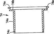
Figure 12 is the left axle head view of the installation axle sleeve shown in Fig. 2,3 and 5 according to first embodiment of the invention;
The longitudinal sectional view that Figure 13 is the installation axle sleeve shown in Figure 12 when the hatching 13-13 of Figure 12 observes;
Figure 14 is the right axle head view of the right cup shown in Figure 10 and 11;
Figure 15 is the left axle head view of the sun gear shown in Fig. 2,3 and 5 according to first embodiment of the invention;
The cutaway view that Figure 16 is the sun gear shown in Figure 15 when the hatching 16-16 of Figure 15 observes is installed with permanent magnet on it; And
Figure 17 is the outer shaft end elevation of the sun gear shown in Figure 15 and 16.
The specific embodiment
Now with reference to accompanying drawing selected embodiment of the present invention is described.By reading present disclosure, those skilled in the art should be understood that, to the only confession example explanation of following description of these embodiment of the present invention, but not are used for being limited by the present invention that appended claims and equivalents thereof limited.
At first please referring to Fig. 1-5, shown bicycle 10 is equipped with the bicycle middle shaft structure 12 according to first embodiment of the invention.Middle axle construction 12 is installed in the central siphon 14 of cycle frame 16.Middle axle construction 12 has right crank arm 18 and the left crank arm 20 that is connected in middle axle construction 12 two ends securely.Because the remaining parts of bicycle 10 is conventional part, therefore, except the part of axle construction 12 in relating to, herein will be not the remaining parts of bicycle 10 be discussed in detail or illustrates.And by reading present disclosure, those skilled in the art should be understood that, in the case without departing from the scope of the present invention, can make various changes to the various assemblies or the part of bicycle 10.
See most clearly in Fig. 2, bicycle middle shaft structure 12 consists essentially of axle 22, the first end mounting structure 24, the second end mounting structure 26, electrical generator or power facility 28 and planetary gear unit 30.Electrical generator 28 is arranged in cyclist's generating in 10 o'clock by bike.Basically, as described below, planetary gear unit 30 is connected between axle 22 and the electrical generator 28 so that make the velocity of rotation of electrical generator 28 faster than axle 22.
Preferably, outer surface also comprises sawtooth and the spline 44 that a plurality of and spline 36 are adjacent, and it is arranged for one of fixing a plurality of sprocket wheels 46 (only illustrating one).Axle 22 outer surface preferably also comprises first group of outside thread 51 that first end 36 with axle 22 is adjacent and second group of adjacent with second end 34 of axle 22 basically outside thread 52.Preferably, effective external diameter of screw thread 51 is greater than effective external diameter of screw thread 52.Outside thread 51 is disposed for the first end mounting structure 24 is fixed thereon firmly.Second outside thread 52 is disposed for the second end mounting structure 26 is fixed thereon firmly.
Preferably, fastener is provided with structure 38 and comprises hold-down bolt 38a, packing ring 38b and binding ring 38c.The outside thread of hold-down bolt 38a meshes with the negative thread 42 of axle 22.Preferably, hold-down bolt 38a is the hollow member that has the hole with torque transfer surface.Hold-down bolt 38a has annular lip, and the flanges abut of itself and left crank arm 20 remains in axial force on second end 34 of axle 22 so that apply with left crank arm 20.Preferably, packing ring 38b places between the annular lip and left crank arm 20 of hold-down bolt 38a.Binding ring 38c is screwed in the left crank arm 20, and is arranged to the annular lip adjacency with hold-down bolt 38a.Preferably, binding ring 38c has the blind hole that a plurality of spaced apart in the circumferential direction being used to put mounting tools.
The first end mounting structure 24 preferably includes right cone 60, right cup 61, a plurality of ball-bearing casing 62 and right-hand member envelope 63.The first end mounting structure 24 is supported on first end 32 of axle 22 on the central siphon 14 rotationally.Especially, right cone 60, right cup 61 and ball-bearing casing 62 have formed clutch shaft bearing group or unit.Right cone 60, right cup 61 and ball-bearing casing 62 become by the common employed hard constructed of rigid materials in bicycle field.
See most clearly in Fig. 2 and 3, right cone 60 is preferably the annular element with tubular portion 60a and annular flange portion 60b.The negative thread 60c of tubular portion 60a engages so that the first end mounting structure 24 is fixed on the axle 22 with the outside thread 51 of axle 22.Tubular portion 60a also has the loop concave 60d of rotatably support ball-bearing casing 62.The annular lip 60b of right cone 60 is preferably rank shape so that formation applies the pressing section of axial force to sprocket wheel 46 and right crank arm 18.Correspondingly, when right cone 60 was installed on axle 22 the outside thread 51, axial force then put on sprocket wheel 46 and the right crank arm 18.
See most clearly in Fig. 9,10 and 11, right cup 61 is preferably become by the hard constructed of rigid materials.Right cup 61 is installed on the central siphon 14 securely.Right cup 61 is preferably the tubular member that comprises tubular portion 61a, exterior support flange 61b and inner annular flange 61c.Preferably, tubular portion 61a also has the outside thread 61d that engages with the negative thread of central siphon 14.Preferably, screw thread 61d is a minus thread.Outer annular flange 61b is an abutment member, and it engages with the axial right-hand member of central siphon 14 when right cup 61 is installed in the central siphon 14 fully.Preferably, outer annular flange 61b has torque transmitting profile (not shown) as being convenient to install used recess.
Inner annular flange 61c preferably has four twist lock otch 61e.These twist lock otch are roughly L shaped configuration so that the part of electrical generator 28 is mounted thereon.Inner annular flange 61c preferably also has the line-entering hole 61f that puts the electric wire W of electrical generator 28 by it.The inner of inner annular flange 61c has is supporting ball-bearing casing 62 so that the concave bearing face 61g that rotates.Correspondingly, ball-bearing casing 62 rotatably supports between the bearing surface 61g of the bearing surface 60d of right cone 60 and right cup, thereby make axle 22 to rotate with respect to central siphon 14.Preferably, ball-bearing casing 62 is become by the hard constructed of rigid materials such as metallic material.
Preferably, containment member 63 is configured to by flexible, elaxtic seal such as elastomeric material.Sealing 63 preferably is installed in the interior groove that is formed on the tubular portion 61a inside face.
As shown in Figure 2, the second end mounting structure 26 consists essentially of left cone 64, left cup 65, a plurality of ball-bearing casing 66 and annular end envelope 67.Therefore, the second end mounting structure 26 is arranged to support rotationally with respect to central siphon 40 left end 34 of axle 22.Left side cone 64, left cup 65 and ball-bearing casing 66 become by the common employed hard constructed of rigid materials in bicycle field.
Preferably, by being installed on the accidental release that jam nut 68 on axle 22 and packing ring 69 can prevent left cone 64.Especially, nut 68 has the negative thread that engages with outside thread 52 so that left cone 64 is applied axial force.
As shown in Figure 2, left cup 65 preferably is configured to by hard rigid material such as metallic material.Left side cup 65 is installed on the left end of central siphon 14 securely.In the embodiment shown, left cup 65 is for having the tubular member of outer tubular member 65a, annular ledge flange 65b and inner annular flange 65c.The outside face of tubular portion 65a have be positioned at central siphon 14 left ends on the outside thread 65d that engages according to thread connecting mode of screw thread.Preferably, screw thread 65d is a right-hand screw thread.Thereby support flange 65b extends from the outer end of tubular portion 65a and forms annular ledge, and this bearing contacts with the end of central siphon 14 when left cup is screwed in the left end of central siphon 14 fully.Preferably, the outer surface of annular lip 65d has a plurality of recess (not shown) that form the torque transmitting surface.
Inner annular flange 65c preferably includes a plurality of sawtooth or spline 65e, and they are formed on the inboard of inner annular flange 65c so that engage with planetary gear unit 30, and are as described below.And inner annular flange 65c preferably has the annular concave bearing face 65f that rotatably support ball-bearing casing 66.
Preferably, end envelope 67 is installed on and is formed at the extending axially in the groove on the part of inner annular flange 65c.Therefore, sealing 67 is arranged for and prevents that dirt from entering middle axle construction 12 by the slit between left cone 64 and the left cup 65.
Still referring among Fig. 2, electrical generator or power facility 28 are generally the assembly of comparison routine.Therefore, except about the content of the present invention, will no longer discuss in more detail or illustrate herein electrical generator 28.Basically, electrical generator 28 comprises yoke unit 70 and magnet unit 71.Yoke unit 70 comprises stationary part, and magnet unit 71 comprises rotating element.Therefore, in this embodiment, yoke unit 70 is arranged to be supported on the central siphon 14 and is fixed thereon, and magnet unit 71 is arranged to rotate around axle 22 by planetary gear unit 30.
See most clearly in Fig. 2 and 3, yoke unit 70 consists essentially of power coil 72, yoke 73, axle sleeve 74 and captive nut 75 is installed.Power coil 72 forms the stator with bobbin, is twining coil on this bobbin.Power coil 72 has flexible cord or line W, and it is connected on one or more electrical equipments electric gear-change as shown in fig. 1.In other words, power coil 72 produces the electric energy that transfers to electrical equipment by flexible cord W with respect to magnet unit 71 rotations.Preferably, yoke 73 by a pair of comprise be used for around and the cup-shape member that supporting the pawl of power coil 72 be configured to.For example, the structure of power coil 72 and yoke 73 can be arranged to be similar to U.S. Patent No. 6,409, the corresponding part of disclosed electrical generator in 197.Yoke 73 is fixed on the outer surface that axle sleeve 74 is installed.
Preferably, axle sleeve 74 being installed is become by the hard constructed of rigid materials.In Fig. 3 and 12-14, see most clearly, axle sleeve 74 is installed for having the tubular member of tubular portion 74a and annular ledge part 74b.Annular ledge part 74b extends radially outward from first end of tubular portion 74a.Second end of tubular portion 74a has the outside thread 74c that is receiving captive nut 75 according to thread connecting mode.After being screwed into captive nut 75 on the tubular portion 74a by screw thread 74c, power coil 72 and yoke 73 just are mounted thereon securely.Preferably, captive nut 75 applies sufficient axial force so that make power coil 72 and yoke 73 not rotate with respect to axle sleeve 74 is installed.Annular lip 74b has coiling opening or slit 74d so that make electric flexible cord W therefrom to pass.Annular lip 74b preferably also comprises a plurality of braking element 74e.Braking element 74e is arranged so that they can be received among the twist lock opening 61e of right cup 61.Especially, after braking element 74e inserts the increasing zone of twist lock opening 61e, make braking element 74e within twist lock opening 61e, along the circumferential direction move thereby make installation axle sleeve 74 reverse or rotate, be fixed in firmly on the right cup 61 so that axle sleeve 74 will be installed with respect to right cup 61.Because right cup 61 is fixed on the central siphon 14, so yoke unit 70 also is connected on the central siphon 14 securely by cup 61.
Review Fig. 2-5, planetary gear unit 30 consists essentially of gear ring 81, set collar 82, geometrical clamp 83, gear stand 84, three planetary wheels 85 and sun gears 86.Magnet unit 71 is installed on the sun gear 86 securely so that make magnet unit 71 with sun gear 86 70 rotations around the yoke unit.Correspondingly, planetary gear unit 30 is connected between the axle 22 and the magnet unit 71 of electrical generator 28 so that make the rotating speed of magnet unit 71 (rotating element) of electrical generator 28 faster than the rotating speed of axle 22.Preferably, the magnet along the circumferential direction placed around yoke unit 70 of magnet unit more than 71 according to concentric manner.Especially, the rotation of axle 22 being passed to permanent magnet thereby permanent magnet is installed on the planetary gear unit 30 makes the rotating speed of permanent magnet faster than axle 22.
Shown in Fig. 2,4 and 5, gear ring 81 is the annular element that is become by the hard constructed of rigid materials.Preferably, gear ring 81 has a plurality of inner sawtooth or spline 81a and a plurality of inner teeth gear teeth 81b.Inner sawtooth 81a engages with the outside sawtooth 65e of left cup 65.Therefore, gear ring 81 is fixed on the left cup 65, and left cup 65 is fixed in again on the bicycle middle shaft pipe 14.In other words, gear ring 81 can not rotate with respect to central siphon 14.The indented joint of inner teeth gear teeth 81b and planetary wheel 85 is so that control the rotation situation of planetary wheel 85, and is as described below.
Shown in Fig. 2,4 and 5, mounting ring 82 comprises a plurality of inner sawtooth or spline 82a and a plurality of outside sawtooth or spline 82b.Inner sawtooth 82a engages so that make mounting ring 82 and axle 22 rotate with the outside sawtooth 64c of left cone 64.Outside sawtooth 82b engages with gear stand 84 so that make gear stand 84 can not rotate with respect to mounting ring 82.Correspondingly, gear stand 84 rotates with axle 22.
Shown in Fig. 2,4 and 5, gear stand 84 is the tubular member that is become by the hard constructed of rigid materials.Gear stand 84 has a plurality of inner sawtooth or spline 84a, and they engage with the outside sawtooth 82b of mounting ring 82 so that make that gear stand 84 and mounting ring 82 are fixed relative to one another.Gear stand 84 also therein heart place comprise the planetary wheel opening 84b that three 120 degree of being separated by distribute.Putting planetary wheel 85 among the planetary wheel opening 84b.Especially, pin 87 is fixed in planetary wheel 85 on the gear stand 84 rotationally.Correspondingly, when axle 22 rotated, gear stand 84 rotated with axle 22, made planetary wheel 85 rotate owing to planetary wheel 85 engages with gear ring 81 simultaneously.
Especially, planetary wheel 85 comprises the first gear parts 85a and the second gear parts 85b.Compare with the second gear parts 85b, the first gear parts 85a diameter is littler, and the number of teeth amount that along the circumferential direction distributes still less.The tooth of the first gear parts 85a engages with the wheel tooth 81b of gear ring 81.Therefore, when gear stand rotated, the tooth of the first gear parts 85a caused planetary wheel 85 to rotate with the engaging of wheel tooth 81b of gear ring 81.Thereby this rotation of each planetary wheel 85 is transferred to sun gear 86 makes sun gear 86 rotate with fast speeds around axle 22.
As Fig. 2,3,5 and 15-17, sun gear 86 comprises the first tubular portion 86a and the second tubular portion 86b.The first tubular portion 86a has the permanent magnet 78 that is installed on its inside face.Therefore, permanent magnet 78 rotates with sun gear 86.The second tubular portion 86b has external gear teeth 86c and negative thread 86d.External gear teeth 86c engages with the wheel tooth of the second gear parts 85b of planetary wheel 85.Correspondingly, the rotation of planetary wheel 85 causes sun gear 86 to rotate.
Preferably, shown in Fig. 2 and 3, binding ring 88 is screwed on the negative thread 86d of sun gear 86.The annular ledge flange of binding ring 88 is arranged to planetary wheel 85 is remained on the external gear teeth 86c.
Be used in this article describe when of the present invention, following directivity speech " forward, backward, the top, downwards, vertical, level, below and laterally " and other similar directivity speech refer to respect to those directions that are equipped with bicycle of the present invention.Correspondingly, when being used for describing when of the present invention, these speech are appreciated that for being equipped with bicycle of the present invention.Degree adverb used herein for example " basically ", " approximately " and " being similar to " etc. is meant that the item of change has rational departure so that guarantee that net result remarkable change can not take place.If deviation can not negate the meaning of its speech of changing, these speech should be interpreted as comprising the deviation at least ± 5% of the item of changing.
Although only selected selected embodiment that the present invention has been carried out the example explanation, but by reading present disclosure, those skilled in the art should be understood that, under the situation that does not deviate from the scope of the present invention defined in the appended claims, can make various changes and remodeling at this.In addition, more than only be used for the example explanation to describing according to an embodiment of the invention, and be not to be used for to limiting as the present invention that appended claims and equivalents thereof limited.
Claims (10)
1. bicycle middle shaft structure comprises:
Axle, it has first end and second end;
Electrical generator, it is installed on the axle, and has stationary part and rotating element; And
Planetary gear unit, it is connected between the rotating element of axle and electrical generator, and described planetary gear unit comprises:
Be installed on the sun gear on the rotating element of electrical generator,
Be mounted to the planetary wheel that rotates with axle, described planetary wheel comprises first gear parts and more second gear parts of number of teeth amount that greatly and along the circumferential direction distributes than this first gear parts diameter,
Be mounted to the gear stand that rotates with axle, gear stand is supporting planetary wheel,
And be fixed in fixed gear ring on the fixed frame part,
Described the 1st gear parts engages with the wheel tooth of gear ring, and the wheel tooth of sun gear engages with second gear parts, makes sun gear rotate when axle rotates, thereby makes the velocity of rotation of rotating element of electrical generator be higher than the rotating speed of axle.
2. bicycle middle shaft structure according to claim 1, wherein
The stationary part of electrical generator comprises the yoke unit, and the rotating element of electrical generator comprises magnet unit.
3. bicycle middle shaft structure according to claim 1, wherein
The stationary part of electrical generator places within the rotating element of electrical generator in concentric mode.
4. bicycle middle shaft structure according to claim 1, wherein
The stationary part of electrical generator comprises the yoke unit that is installed on the axle sleeve that centers on axle, and described axle sleeve places within the rotating element of the electrical generator that comprises magnet unit in concentric mode.
5. bicycle middle shaft structure according to claim 4, wherein
One end of the axle sleeve of the stationary part of electrical generator has mounting structure.
6. bicycle middle shaft structure according to claim 5, wherein
The mounting structure of axle sleeve has line inlet port, is placing the electric flexible cord of yoke unit in the described line inlet port.
7. bicycle middle shaft structure according to claim 5, wherein
Axle sleeve has line inlet port, is placing the electric flexible cord of yoke unit in the described line inlet port.
8. bicycle middle shaft structure according to claim 5, wherein
The first end mounting structure and the second end mounting structure are supported on the right-hand member and the left end of axle on the axle sleeve respectively rotationally, right cone, right outside cup and ball-bearing casing form the clutch shaft bearing group of the first end mounting structure, left side cone, left outside cup and ball-bearing casing form second bearing set of the second end mounting structure, and the mounting structure of axle sleeve is connected on the outside cup of bearing set.
9. bicycle middle shaft structure according to claim 8, wherein
Axle sleeve and outside cup all have line inlet port, are placing the electric flexible cord of yoke unit in the described line inlet port.
10. bicycle middle shaft structure according to claim 8, wherein
Fixed gear ring is installed on the left outside cup of second bearing set, and the stationary part of electrical generator has the mounting structure on the right outside cup that is connected in the clutch shaft bearing group.
Applications Claiming Priority (2)
| Application Number | Priority Date | Filing Date | Title |
|---|---|---|---|
| US10/879,535 US7059989B2 (en) | 2004-06-30 | 2004-06-30 | Bottom bracket structure with dynamo |
| US10/879535 | 2004-06-30 |
Publications (2)
| Publication Number | Publication Date |
|---|---|
| CN1715123A CN1715123A (en) | 2006-01-04 |
| CN100537335C true CN100537335C (en) | 2009-09-09 |
Family
ID=35064926
Family Applications (1)
| Application Number | Title | Priority Date | Filing Date |
|---|---|---|---|
| CNB2005100810739A Expired - Fee Related CN100537335C (en) | 2004-06-30 | 2005-06-29 | Middle shaft structure with dynamo |
Country Status (5)
| Country | Link |
|---|---|
| US (1) | US7059989B2 (en) |
| EP (1) | EP1612132B1 (en) |
| JP (1) | JP4233546B2 (en) |
| CN (1) | CN100537335C (en) |
| TW (1) | TWI250107B (en) |
Families Citing this family (16)
| Publication number | Priority date | Publication date | Assignee | Title |
|---|---|---|---|---|
| JP2005104258A (en) * | 2003-09-30 | 2005-04-21 | Shimano Inc | Electrical instrument holder for bicycle |
| TWM301184U (en) * | 2006-06-19 | 2006-11-21 | De-You Peng | Transmission structure improvement for an electric bicycle |
| ITMI20061549A1 (en) * | 2006-08-03 | 2008-02-04 | Campagnolo Srl | ASSEMBLY OF RIGHT PEDESTAL FOR BICYCLE AND RELATED PEDIVELLA AND CORONA |
| ITMI20061550A1 (en) * | 2006-08-03 | 2008-02-04 | Campagnolo Srl | ASSEMBLY OF THE RIGHT PEDESTAL FOR BICYCLE AND ITS CRANKCASE |
| US8067848B1 (en) | 2008-01-14 | 2011-11-29 | Lixon Vilsaint | Bicycle adapter mobile telephone charger |
| GB2461535A (en) * | 2008-07-02 | 2010-01-06 | Jen-Yen Yen | Electric generator for bicycle |
| US20100019676A1 (en) * | 2008-07-28 | 2010-01-28 | Jen-Yen Yen | Electric generator for bicycle |
| US20100212978A1 (en) * | 2009-02-23 | 2010-08-26 | Wen-Hung Huang | Bicycle with two operation molds |
| TWI435979B (en) * | 2009-09-30 | 2014-05-01 | Ind Tech Res Inst | Swinging device and apparatus for detecting rotating status and information displaying device using the same |
| US9428246B2 (en) * | 2011-12-09 | 2016-08-30 | Shimano Inc. | Bicycle generator and/or shifting device |
| DE102012103355A1 (en) * | 2012-04-17 | 2013-10-17 | Brose Fahrzeugteile Gmbh & Co. Kommanditgesellschaft, Coburg | Drive device for an electric bike |
| US9013080B2 (en) * | 2012-10-01 | 2015-04-21 | Shimano Inc. | Bicycle generator |
| US8777791B1 (en) * | 2013-02-07 | 2014-07-15 | Shimano Inc. | Bicycle drive unit |
| CN106741501B (en) * | 2017-03-08 | 2022-11-08 | 八方电气(苏州)股份有限公司 | Middle axle mounting structure of bicycle or electric bicycle |
| WO2019171859A1 (en) * | 2018-03-05 | 2019-09-12 | 本田技研工業株式会社 | Power generation device for bicycle and bicycle |
| DE102020201212B4 (en) * | 2020-01-31 | 2021-10-07 | Gerd Scheying | Device for energy recovery in two-wheelers with a mid-engine drive unit and method for operating the same |
Citations (2)
| Publication number | Priority date | Publication date | Assignee | Title |
|---|---|---|---|---|
| US2553465A (en) * | 1946-11-30 | 1951-05-15 | Monge Jean Raymond Barthelemy | Manual or power-operated planetary transmission |
| FR2276980B1 (en) * | 1974-07-03 | 1978-01-27 | Herve Jean |
Family Cites Families (8)
| Publication number | Priority date | Publication date | Assignee | Title |
|---|---|---|---|---|
| JPS55141954A (en) | 1979-04-24 | 1980-11-06 | Stanley Electric Co Ltd | Dynamo for bicycle |
| JPS55144744A (en) * | 1979-04-27 | 1980-11-11 | Stanley Electric Co Ltd | Dynamo for bicycle |
| US5115159A (en) * | 1989-10-25 | 1992-05-19 | Bridgestone Cycle Co., Ltd. | Built-in generator for bicycle |
| US5600191A (en) * | 1994-12-19 | 1997-02-04 | Yang; Chen-Chi | Driving assembly for motor wheels |
| JPH1035560A (en) * | 1996-07-22 | 1998-02-10 | Pioneer Seimitsu Kk | Bicycle generator and its attaching method |
| GB2334154B (en) * | 1998-02-02 | 2000-04-05 | Inventive Step Limited | Electricity generation for pedalled vehicles |
| US6296072B1 (en) * | 1999-01-20 | 2001-10-02 | Opti-Bike Llc | Electric bicycle and methods |
| JP3477134B2 (en) * | 2000-01-31 | 2003-12-10 | 株式会社シマノ | Bicycle hub |
-
2004
- 2004-06-30 US US10/879,535 patent/US7059989B2/en not_active Expired - Fee Related
-
2005
- 2005-02-18 TW TW094104898A patent/TWI250107B/en not_active IP Right Cessation
- 2005-04-26 EP EP05009122A patent/EP1612132B1/en not_active Expired - Fee Related
- 2005-06-24 JP JP2005185518A patent/JP4233546B2/en not_active Expired - Fee Related
- 2005-06-29 CN CNB2005100810739A patent/CN100537335C/en not_active Expired - Fee Related
Patent Citations (2)
| Publication number | Priority date | Publication date | Assignee | Title |
|---|---|---|---|---|
| US2553465A (en) * | 1946-11-30 | 1951-05-15 | Monge Jean Raymond Barthelemy | Manual or power-operated planetary transmission |
| FR2276980B1 (en) * | 1974-07-03 | 1978-01-27 | Herve Jean |
Also Published As
| Publication number | Publication date |
|---|---|
| JP2006015987A (en) | 2006-01-19 |
| CN1715123A (en) | 2006-01-04 |
| US20060003860A1 (en) | 2006-01-05 |
| US7059989B2 (en) | 2006-06-13 |
| TW200600406A (en) | 2006-01-01 |
| EP1612132B1 (en) | 2011-06-29 |
| TWI250107B (en) | 2006-03-01 |
| EP1612132A3 (en) | 2008-01-23 |
| EP1612132A2 (en) | 2006-01-04 |
| JP4233546B2 (en) | 2009-03-04 |
Similar Documents
| Publication | Publication Date | Title |
|---|---|---|
| CN100537335C (en) | Middle shaft structure with dynamo | |
| TWI250951B (en) | Bottom bracket structure with dynamo | |
| EP1342657B2 (en) | Sprocket assembly for a bicycle | |
| TWI702168B (en) | Bicycle sprocket assembly | |
| CN101224782B (en) | Bicycle chain wheel assembly | |
| US6983672B2 (en) | Bicycle crank axle bearing assembly | |
| US20040079612A1 (en) | Bicycle hub dynamo with a freewheel | |
| CN106321741B (en) | The planetary gear train of transmission device for motor | |
| CN102079360A (en) | Bicycle sprocket support assembly | |
| CN101088851A (en) | Bicycle sprocket assembly | |
| JP2006123895A (en) | Bicycle crankset | |
| JP2008254728A (en) | Bicycle shaft component | |
| US9139254B2 (en) | Universal low-friction bicycle hub transmission | |
| CN104755367B (en) | It is electronic to use hub unit and electric bicycle | |
| US9487267B2 (en) | Bicycle bottom bracket assembly | |
| US5522611A (en) | Multiple sprocket chainwheel for bicycle derailleur | |
| CN107571960A (en) | Torque detection transmission device and electric bicycle middle motor applying same | |
| CN102951251A (en) | Transmission and traction motor module using the same | |
| EP3789285A1 (en) | Drive system for an electric bicycle | |
| CN212242816U (en) | Bicycle hub | |
| US20020129676A1 (en) | Bottom bracket bearing axle mounting arrangement | |
| KR101870441B1 (en) | Planetary Gear Train for Transmission of e-bike motor | |
| US20220388597A1 (en) | Front Motor Drive Bicycle With Side Mounted Wheels | |
| CN2236413Y (en) | Assembly of chain wheel | |
| TW202402616A (en) | Rear sprocket for human-powered vehicle and sprocket carrier configurated in supporting the same improving the degree of freedom in arranging a structure for improving gear shifting performance |
Legal Events
| Date | Code | Title | Description |
|---|---|---|---|
| C06 | Publication | ||
| PB01 | Publication | ||
| C10 | Entry into substantive examination | ||
| SE01 | Entry into force of request for substantive examination | ||
| C14 | Grant of patent or utility model | ||
| GR01 | Patent grant | ||
| CF01 | Termination of patent right due to non-payment of annual fee |
Granted publication date: 20090909 Termination date: 20200629 |
|
| CF01 | Termination of patent right due to non-payment of annual fee |