CN100520503C - Vacuum pumping system, driving method thereof, apparatus having the same, and method of transferring substrate by using the system - Google Patents
Vacuum pumping system, driving method thereof, apparatus having the same, and method of transferring substrate by using the system Download PDFInfo
- Publication number
- CN100520503C CN100520503C CNB2005100535125A CN200510053512A CN100520503C CN 100520503 C CN100520503 C CN 100520503C CN B2005100535125 A CNB2005100535125 A CN B2005100535125A CN 200510053512 A CN200510053512 A CN 200510053512A CN 100520503 C CN100520503 C CN 100520503C
- Authority
- CN
- China
- Prior art keywords
- processing chamber
- valve
- booster pump
- chamber
- pump
- Prior art date
- Legal status (The legal status is an assumption and is not a legal conclusion. Google has not performed a legal analysis and makes no representation as to the accuracy of the status listed.)
- Expired - Fee Related
Links
Images


Classifications
-
- H—ELECTRICITY
- H10—SEMICONDUCTOR DEVICES; ELECTRIC SOLID-STATE DEVICES NOT OTHERWISE PROVIDED FOR
- H10P—GENERIC PROCESSES OR APPARATUS FOR THE MANUFACTURE OR TREATMENT OF DEVICES COVERED BY CLASS H10
- H10P72/00—Handling or holding of wafers, substrates or devices during manufacture or treatment thereof
- H10P72/04—Apparatus for manufacture or treatment
- H10P72/0451—Apparatus for manufacturing or treating in a plurality of work-stations
- H10P72/0452—Apparatus for manufacturing or treating in a plurality of work-stations characterised by the layout of the process chambers
-
- H—ELECTRICITY
- H10—SEMICONDUCTOR DEVICES; ELECTRIC SOLID-STATE DEVICES NOT OTHERWISE PROVIDED FOR
- H10P—GENERIC PROCESSES OR APPARATUS FOR THE MANUFACTURE OR TREATMENT OF DEVICES COVERED BY CLASS H10
- H10P72/00—Handling or holding of wafers, substrates or devices during manufacture or treatment thereof
- H10P72/04—Apparatus for manufacture or treatment
- H10P72/0402—Apparatus for fluid treatment
-
- H—ELECTRICITY
- H10—SEMICONDUCTOR DEVICES; ELECTRIC SOLID-STATE DEVICES NOT OTHERWISE PROVIDED FOR
- H10P—GENERIC PROCESSES OR APPARATUS FOR THE MANUFACTURE OR TREATMENT OF DEVICES COVERED BY CLASS H10
- H10P72/00—Handling or holding of wafers, substrates or devices during manufacture or treatment thereof
- H10P72/04—Apparatus for manufacture or treatment
- H10P72/0451—Apparatus for manufacturing or treating in a plurality of work-stations
- H10P72/0452—Apparatus for manufacturing or treating in a plurality of work-stations characterised by the layout of the process chambers
- H10P72/0454—Apparatus for manufacturing or treating in a plurality of work-stations characterised by the layout of the process chambers surrounding a central transfer chamber
-
- H—ELECTRICITY
- H10—SEMICONDUCTOR DEVICES; ELECTRIC SOLID-STATE DEVICES NOT OTHERWISE PROVIDED FOR
- H10P—GENERIC PROCESSES OR APPARATUS FOR THE MANUFACTURE OR TREATMENT OF DEVICES COVERED BY CLASS H10
- H10P72/00—Handling or holding of wafers, substrates or devices during manufacture or treatment thereof
- H10P72/04—Apparatus for manufacture or treatment
- H10P72/0451—Apparatus for manufacturing or treating in a plurality of work-stations
- H10P72/0452—Apparatus for manufacturing or treating in a plurality of work-stations characterised by the layout of the process chambers
- H10P72/0456—Apparatus for manufacturing or treating in a plurality of work-stations characterised by the layout of the process chambers in-line arrangement
-
- Y—GENERAL TAGGING OF NEW TECHNOLOGICAL DEVELOPMENTS; GENERAL TAGGING OF CROSS-SECTIONAL TECHNOLOGIES SPANNING OVER SEVERAL SECTIONS OF THE IPC; TECHNICAL SUBJECTS COVERED BY FORMER USPC CROSS-REFERENCE ART COLLECTIONS [XRACs] AND DIGESTS
- Y10—TECHNICAL SUBJECTS COVERED BY FORMER USPC
- Y10T—TECHNICAL SUBJECTS COVERED BY FORMER US CLASSIFICATION
- Y10T137/00—Fluid handling
- Y10T137/8593—Systems
- Y10T137/85978—With pump
- Y10T137/86083—Vacuum pump
-
- Y—GENERAL TAGGING OF NEW TECHNOLOGICAL DEVELOPMENTS; GENERAL TAGGING OF CROSS-SECTIONAL TECHNOLOGIES SPANNING OVER SEVERAL SECTIONS OF THE IPC; TECHNICAL SUBJECTS COVERED BY FORMER USPC CROSS-REFERENCE ART COLLECTIONS [XRACs] AND DIGESTS
- Y10—TECHNICAL SUBJECTS COVERED BY FORMER USPC
- Y10T—TECHNICAL SUBJECTS COVERED BY FORMER US CLASSIFICATION
- Y10T137/00—Fluid handling
- Y10T137/8593—Systems
- Y10T137/85978—With pump
- Y10T137/86131—Plural
- Y10T137/86139—Serial
Landscapes
- Compressors, Vaccum Pumps And Other Relevant Systems (AREA)
- Physical Vapour Deposition (AREA)
- Container, Conveyance, Adherence, Positioning, Of Wafer (AREA)
Abstract
本发明涉及一种装置,该装置包括:一转移单元,该转移单元处于大气条件之下且其中具有一机械手;和至少一个处理腔室,该处理腔室连接到转移单元的一侧且在该处理腔室与该转移单元之间具有一槽阀,且可交替地处于真空条件和大体条件之下。

The invention relates to an apparatus comprising: a transfer unit which is under atmospheric conditions and has a robot therein; and at least one processing chamber connected to one side of the transfer unit and in the There is a slot valve between the processing chamber and the transfer unit, and can be alternately under vacuum conditions and general conditions.
Description
本发明主张2004年3月8日申请的韩国专利申请案第2004-0015544号、2004年3月16日申请的第2004-0017627号、2004年3月17日申请的第2004-0017832号和2005年2月23日申请的第2005-0014819号的权利,这些申请案以引用的方式并入本文中。The present invention claims Korean Patent Application No. 2004-0015544 filed on March 8, 2004, No. 2004-0017627 filed on March 16, 2004, No. 2004-0017832 filed on March 17, 2004, and 2005 2005-0014819 filed February 23, 2005, which are incorporated herein by reference.
技术领域 technical field
本发明涉及抽真空系统、其驱动方法、具有此系统的装置和使用此系统转移基板的方法。The present invention relates to an evacuation system, a driving method thereof, a device having such a system and a method of transferring a substrate using such a system.
背景技术 Background technique
通常,半导体设备或液晶显示(LCD)设备通过重复在基板上沉积薄膜的步骤、使用光阻材料进行照相平版印刷的步骤、选择性地蚀刻薄膜的步骤和清洗基板的步骤几次或几十次而在制成。用于半导体设备或LCD设备的制造过程的这些步骤可在最佳条件下利用一具有处理腔室的装置来执行。Generally, a semiconductor device or a liquid crystal display (LCD) device repeats the steps of depositing a thin film on a substrate, photolithography using a photoresist material, selectively etching a thin film, and cleaning the substrate several or dozens of times. And in made. These steps for the manufacturing process of a semiconductor device or an LCD device can be performed under optimal conditions using an apparatus having a processing chamber.
近来,一种群集器因为其具有在短时期内处理大量基板的优越处理能力而被广泛地用作用于制造半导体设备和LCD设备的装置,此群集器包括用于处理基板的处理腔室、用于暂时存储该等基板的加载锁定腔室(load-lockchamber)和在该处理腔室和该加载锁定腔室之间用于将基板移进移出该处理腔室的转移腔室。Recently, a clusterer including a processing chamber for processing a substrate, a A load-lock chamber for temporarily storing the substrates and a transfer chamber between the processing chamber and the load-lock chamber for moving substrates into and out of the processing chamber.
图1为显示根据先前技术的群集器的示意图。该群集器可用于制造LCD设备以及半导体设备。FIG. 1 is a schematic diagram showing a cluster according to the prior art. The cluster can be used to manufacture LCD devices as well as semiconductor devices.
在图1中,一群集器包括转移腔室70、复数个处理腔室80、第一加载锁定腔室40与第二加载锁定腔室50、转移单元10和第一加载端口(loadport)20与第二加载端口30。所述复数个处理腔室80和第一加载锁定腔室40与第二加载锁定腔室50被连接到转移腔室70的各侧上。所述转移单元10被连接到第一加载锁定腔室40与第二加载锁定腔室50的侧面,且第一加载端口20与第二加载端口30被连接到转移单元10的侧面。In FIG. 1, a cluster includes a
通常,在基板上沉积薄膜的步骤、蚀刻薄膜的步骤和清洗基板的步骤是在处理腔室80中于高真空条件下进行。转移腔室70充当利用转移腔室机械手72在一个处理腔室80与另一个处理腔室80之间或在处理腔室之一80与加载锁定腔室40和50两者之一之间转移基板的空间。转移腔室70也保持真空条件。在每个处理腔室80与转移腔室70之间设立了槽阀(未图示)。Typically, the steps of depositing a thin film on the substrate, etching the thin film and cleaning the substrate are performed in the
转移单元10可称为设备前端模块(EFEM)。转移单元10充当利用其中的机械手12将未经处理的基板移到加载锁定腔室40和50中或将已经处理的基板从加载锁定腔室40和50移到外部去的空间。转移单元10总是保持大气条件,并连接到第一和第二加载端口20和30且之间设置了门(未图示)。收纳基板的盒子设置在加载端口20和30中。The
可将用于设置于机械手12上的基板的平滑区域对准(flat zonealignment)的对准器60装配在转移单元10的一侧。An
因为转移腔室70处于真空条件下而转移单元10处于大气条件下,所以将第一加载锁定腔室40和第二加载锁定腔室50设置在转移腔室70与转移单元10之间作为缓冲。当基板进出时,第一锁定腔室40和第二加载锁定腔室50交替地处于真空条件和大气条件下。Since the
槽阀设立在第一和第二加载锁定腔室40和50与转移单元10之间以及第一和第二加载锁定腔室40和50与转移腔室70之间。Slot valves are established between the first and second
收纳基板的盒子设置于第一加载端口20和第二加载端口30中,且机械手12将基板从第一加载端口20和第二加载端口30两者之一中转移到转移单元10中。接着,在机械手12在对准器60中实现了基板的平滑区域对准之后,机械手12将基板转移到第一和第二加载锁定腔室40和50两者之一中。A box for accommodating substrates is disposed in the
举例而言,如果第一加载锁定腔室40的门(未图示)是打开的,那么机械手12将基板加载到第一加载锁定腔室40中。然后,当机械手12返回后,门关闭,并执行抽气步骤以将第一加载锁定腔室40从大气条件转换到与转移腔室70相同的真空条件。For example, if the door (not shown) of the first
当第一加载锁定腔室40在真空条件下时,第一加载锁定腔室40与转移腔室70之间的门(未图示)是打开的,转移腔室机械手72进入第一加载锁定腔室40以将基板移动到处理腔室80之一中。When the first
在基板在处理腔室80中接受处理之后,以与上述过程相反的顺序将基板取出。此时,基板从转移腔室70中转移出来,进入加载锁定腔室40或50,接着执行用于使加载锁定腔室40或50通风的步骤以将加载锁定腔室40或50从真空条件改变为大气条件。在通风步骤之后,转移单元10的机械手12取出加载锁定腔室40或50中的基板并将基板转移到加载端口20或30中的盒子中。After the substrate is processed in the
顺便提及的是,根据先前技术的群集器需要一在真空条件下的转移腔室70和至少一个加载锁定腔室40或50以使在高真空条件下的处理腔室80可与外部大气条件连接。由于转移腔室70和转移腔室自动机12,此导致群集器的大占据面积和群集器的高成本。Incidentally, the clusters according to the prior art require a
同时,如上所述,因为加载锁定腔室40或50交替地位于真空条件和大气条件下,且处理腔室80和转移腔室70总是在真空条件下,所以该群集器应包括一抽真空系统和一通风系统。Also, as mentioned above, since the
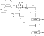
图2为根据先前技术的处理腔室、抽真空系统和通风系统的示意图。如图所示,一基座87设置在处理腔室80内以在其上加载基板,且一注气部件84(如莲蓬头)设置在基座87上方。注气部件84通过穿过穹形腔室盖81的气体管道85连接到处理气体存储单元86。一穿过处理腔室80的侧壁或下侧且突出在处理腔室80内的注射器可用作注气部件84。所述腔室盖81可具有各种形状而不限于穹形。Figure 2 is a schematic diagram of a processing chamber, evacuation system and ventilation system according to the prior art. As shown, a susceptor 87 is disposed within the
一涡轮分子泵(TMP)90设置于处理腔室80下,且一摆动阀83设置在处理腔室80与TMP 90之间。A turbomolecular pump (TMP) 90 is disposed under the
所述抽真空系统包括第一排气管道91、升压泵98、干式泵99和第二排气管道92。第一排气管道91的一端连接到处理腔室80的下部,且升压泵98和干式泵99连接到第一排气管道91的另一端。第二排气管道92的一端连接到TMP 90,且第二排气管道92的另一端连接到在升压泵98之前的第一排气管道91。The vacuum system includes a first exhaust pipeline 91 , a booster pump 98 , a dry pump 99 and a second exhaust pipeline 92 . One end of the first exhaust pipe 91 is connected to the lower portion of the
干式泵99可称为低真空泵且可广泛用于从大气压力到约1mTorr(毫托)的压力条件下。干式泵99分为凸轮(CAM)型和螺旋型。The dry pump 99 may be referred to as a roughing pump and may be widely used under pressure conditions from atmospheric pressure to about 1 mTorr (milliTorr). The dry pump 99 is classified into a cam (CAM) type and a screw type.
如图3所示意说明的,升压泵98包括气缸98a和在气缸98a中的两个茧形转子98b,其中该等转子98b分别通过其轴上的传动齿轮一致地在相反方向上旋转。As schematically illustrated in FIG. 3, the booster pump 98 includes a
因此,进入升压泵98的入口中的气体因为转子98b的旋转排向出口,紧密地封闭在气缸98a与转子98b之间的空间中,且气体通过一在升压泵98之后的附加泵(例如,图2中的干式泵99)而排到空气中。Therefore, the gas entering the inlet of the booster pump 98 is discharged toward the outlet due to the rotation of the
因为在转子间和转子与气缸之间保留了约0.1mm到约0.3mm的狭窄间隙,所以润滑油是并非必需的。因此,具有可进行无油真空排气的优点。慢速抽气管道93从快速抽气管道91(即第一排气管道91)延伸。因为慢速抽气管道93具有比第一排气管道91小的横截面积,所以慢速抽气管道93与第一排气管道91相比具有相对低的排气导流和相对慢的抽气速度。如果在抽气的早期阶段抽气速度较快,那么可能会损害装置的基板和组件。因此,使用慢速抽气管道93来减少所述损害。Since a narrow gap of about 0.1 mm to about 0.3 mm remains between the rotors and between the rotor and the cylinder, lubricating oil is not necessary. Therefore, there is an advantage that oil-free vacuum exhaust is possible. The slow suction pipe 93 extends from the fast suction pipe 91 (ie, the first exhaust pipe 91 ). Because the slow suction duct 93 has a smaller cross-sectional area than the first exhaust duct 91, the slow suction duct 93 has a relatively low exhaust conduction and a relatively slow suction compared with the first exhaust duct 91. Gas speed. If the pumping rate is fast in the early stages of pumping, it may damage the substrate and components of the device. Therefore, a slow suction line 93 is used to reduce the damage.
在处理腔室80和升压泵98之间装配三向阀96,使慢速抽气管道93从第一排气管道91分叉。慢速抽气管道93的一端连接到三向阀96的一个出口,且慢速抽气管道93的另一端连接到升压泵98与三向阀96之间的第一排气管道91。因此,通过三向阀从慢速抽气管道93和第一排气管道91中判定气体的排气路径。A three-way valve 96 is installed between the
在第二排气管道92的中间设置一中间阀97,且该中间阀97根据TMP 90的工作而打开和关闭。An intermediate valve 97 is provided in the middle of the second exhaust pipe 92, and the intermediate valve 97 is opened and closed according to the operation of the TMP 90.
为了利用上述以上抽真空系统将腔室从大气条件改变到真空条件,首先驱动升压泵98和干式泵99,且气体通过控制三向阀96经慢速抽气管道93排出。当处理腔室80处于某压力下时,再次控制三向阀96,因此气体通过第一排气管道95而非该慢速抽气管道93排出。此时,升压泵98和干式泵99同时工作。In order to change the chamber from the atmospheric condition to the vacuum condition by using the above vacuum system, the booster pump 98 and the dry pump 99 are first driven, and the gas is discharged through the slow pumping pipeline 93 through the control three-way valve 96 . When the
当处理腔室80处于高真空条件下时,处理腔室80下方的摆动阀83打开,且使用TMP 90对处理腔室80抽真空直到处理腔室80的内部达到超高真空条件。通过TMP 90排出的气体是经由中间阀97和第一排气管道93通过升压泵98和干式泵99排出的。When the
然而,因为抽真空系统具有慢速的抽气速度,所以难以频繁使用该抽真空系统,且抽真空系统广泛用于设定装置的步骤中。However, since the vacuuming system has a slow pumping speed, it is difficult to use the vacuuming system frequently, and the vacuuming system is widely used in the step of setting the apparatus.
同时,通常为加载锁定腔室40和50装配一通风系统,加载锁定腔室40和50交替地在大气条件和在真空条件下,且可为处理腔室80或转移腔室70装配该通风系统。意即,当处理腔室80或转移腔室70中的压力由于过度抽真空变得相当低时,应通过提供比如氩(Ar)或氮(N2)的气体来调整处理腔室80或转移腔室70中的压力到最佳压力。另外,在使装置固定不动以用于修理或在其它所需状况下,腔室可位于大气条件下。Meanwhile, a ventilation system is generally equipped for the
图2显示了处理腔室80的通风系统。所述通风系统包括通风管道88和针阀89。通风管道88的一端穿过处理腔室80的侧壁,且通风管道88的另一端连接到通风气体存储单元(未图示),其中包括氩气或氮气。针阀89设立在通风管道88的中间且控制气体的流速。FIG. 2 shows the ventilation system of the
然而,先前技术的通风系统通常在狭窄范围内调整在真空条件下的腔室的压力。因此,如果加宽调整压力的范围,那么通风时间应变得更长。However, prior art ventilation systems usually regulate the pressure of the chamber under vacuum within a narrow range. Therefore, if the range for adjusting the pressure is widened, the ventilation time should become longer.
如果大量的气体流进腔室以缩短通风时间,那么不可能一致维持该腔室的内部温度,且因此降低了该等处理的再生产率。另外,因为可能会由于热冲击而导致装置的退化和粒子的产生,所以在该等处理期间存在周期性使处理腔室通风的限制。If a large amount of gas flows into the chamber to shorten the ventilation time, it is impossible to maintain the internal temperature of the chamber consistently, and thus the reproducibility of the processes is reduced. In addition, there are limitations to periodically venting the process chamber during such processes because degradation of the device and generation of particles may occur due to thermal shock.
发明内容 Contents of the invention
因此,本发明针对抽真空系统、其驱动方法、具有此系统的装置和使用此系统转移基板的方法,其大体上消除了由于先前技术的限制和缺点而引起的一个或多个问题。Accordingly, the present invention is directed to an evacuation system, method of driving the same, apparatus having the same, and method of transferring a substrate using the same that substantially obviate one or more of the problems due to limitations and disadvantages of the prior art.
本发明的一个目的是提供一基板制造装置以用于半导体设备和液晶显示设备,其通过减少所述装置的占据面积和成本而有效地利用了所述装置。An object of the present invention is to provide a substrate manufacturing apparatus for use in semiconductor equipment and liquid crystal display equipment, which effectively utilizes the apparatus by reducing the occupied area and cost of the apparatus.
本发明的另一目的是提供抽真空系统和使用此系统的抽气方法,其加快了处理装置的抽气速度。Another object of the present invention is to provide a vacuum pumping system and a pumping method using the same, which can increase the pumping speed of a processing device.
本发明的另一目的是提供通风系统和使用此系统的通风方法,其通过加快通风速度使腔室内部的温度变化和热冲击减到最小。Another object of the present invention is to provide a ventilation system and a ventilation method using the same, which minimize temperature variation and thermal shock inside a chamber by increasing the ventilation speed.
在下文的描述中将陈述本发明的其它特征和优点,且这些特征和优点从描述中可部分变得显而易见或可通过实践本发明而得知。通过书面描述和其权利要求中特定指出的结构以及附图将实现和获得本发明的该等目的和其他优点。Additional features and advantages of the invention will be set forth in the description which follows, and in part will be obvious from the description, or may be learned by practice of the invention. The objectives and other advantages of the invention will be realized and attained by the structure particularly pointed out in the written description and claims hereof as well as the appended drawings.
为了获得这些和其它优点且根据本发明的目的,如以上具体表达和广泛描述的,一装置包括:一转移单元,其处于大气条件下且其中具有一机械手;和至少一个处理腔室,其连接到该转移单元的一侧且在该处理腔室与该转移单元之间具有一槽阀,且交替地处于真空条件下和在大气条件下。In order to obtain these and other advantages and in accordance with the purpose of the present invention, as embodied and broadly described above, an apparatus comprises: a transfer unit, which is under atmospheric conditions and has a manipulator therein; and at least one processing chamber, which is connected to There is a slot valve to one side of the transfer unit and between the process chamber and the transfer unit, and is alternately under vacuum conditions and under atmospheric conditions.
在另一方面,该装置进一步包括:一连接到该处理腔室的排气管道;依次装配到该排气管道的升压泵和干式泵;和一绕过该升压泵的旁通管道,其中该旁通管道的一端连接到升压泵与干式泵之间的排气管道,且该旁通管道的另一端连接到升压泵之前的排气管道。此外,该装置进一步包括一在该升压泵与该干式泵之间的第一三向阀和一在该升压泵之前的第二三向阀,其中该旁通管道的一端和另一端分别连接到该第一三向阀和该第二三向阀。In another aspect, the apparatus further comprises: an exhaust pipe connected to the processing chamber; a booster pump and a dry pump sequentially fitted to the exhaust pipe; and a bypass pipe bypassing the booster pump , wherein one end of the bypass pipeline is connected to the exhaust pipeline between the booster pump and the dry pump, and the other end of the bypass pipeline is connected to the exhaust pipeline before the booster pump. In addition, the device further includes a first three-way valve between the booster pump and the dry pump and a second three-way valve before the booster pump, wherein one end and the other end of the bypass pipe respectively connected to the first three-way valve and the second three-way valve.
在另一方面,该装置进一步包括至少一个连接到该处理腔室的通风管道和一通风气体存储单元;和一设立在至少一个通风管道中间的第一加热单元。In another aspect, the apparatus further includes at least one ventilation duct connected to the processing chamber and a ventilation gas storage unit; and a first heating unit disposed between the at least one ventilation duct.
在另一方面,该装置进一步包括至少一个连接到该转移单元的另一侧的加载端口。In another aspect, the device further includes at least one loadport connected to the other side of the transfer unit.
在另一方面,一种加载基板的方法包括:利用设立在该转移单元中的机械手将基板运载到一在大气条件下的转移单元中;利用机械手将基板从转移单元转移到一在大气条件下的处理腔室中;和抽真空处理腔室的内部。抽真空包括使用一干式泵的第一抽气和同时使用该干式泵和一升压泵的第二抽气,其中该升压泵和该干式泵依次连接到该处理腔室。In another aspect, a method of loading a substrate includes: using a manipulator built in the transfer unit to carry the substrate into a transfer unit under atmospheric conditions; using the manipulator to transfer the substrate from the transfer unit to an atmospheric condition in the processing chamber; and evacuate the interior of the processing chamber. The evacuation includes a first evacuation using a dry pump and a second evacuation using both the dry pump and a booster pump, wherein the booster pump and the dry pump are sequentially connected to the processing chamber.
在另一方面,一种将基板从该处理腔室卸载的方法包括:使处理腔室通风,使处理腔室的内部从真空条件改变为大气条件;利用转移单元中的机械手将基板从处理腔室转移到一在大气条件下的转移单元;和利用该机械手将基板从转移单元取出。In another aspect, a method of unloading a substrate from the processing chamber includes: ventilating the processing chamber to change the interior of the processing chamber from a vacuum condition to an atmospheric condition; utilizing a robot in a transfer unit to remove the substrate from the processing chamber transferring the chamber to a transfer unit under atmospheric conditions; and removing the substrate from the transfer unit using the robot.
在另一方面,一种抽真空系统包括:一连接到一腔室的排气管道;依次连接到该排气管道的升压泵和干式泵;和一绕过该升压泵的旁通管道,其中该旁通管道的一端连接到该升压泵与该干式泵之间的排气管道,且旁通管道的另一端连接到在该升压泵之前的排气管道。该系统进一步包括一在该升压泵与该干式泵之间的第一三向阀和一在升压泵之前的第二三向阀,其中该旁通管道的一端和另一端分别连接到该第一三向阀和该第二三向阀。In another aspect, an evacuation system includes: an exhaust conduit connected to a chamber; a booster pump and a dry pump sequentially connected to the exhaust conduit; and a bypass bypassing the booster pump pipeline, wherein one end of the bypass pipeline is connected to the exhaust pipeline between the booster pump and the dry pump, and the other end of the bypass pipeline is connected to the exhaust pipeline before the booster pump. The system further includes a first three-way valve between the booster pump and the dry pump and a second three-way valve before the booster pump, wherein one end and the other end of the bypass pipe are respectively connected to The first three-way valve and the second three-way valve.
在另一方面,一种使用依次设立在一排气管道中的升压泵和干式泵来抽真空一腔室的内部的方法包括:使用干式泵的第一抽气;和同时使用干式泵和升压泵的第二抽气。In another aspect, a method of evacuating the interior of a chamber using a booster pump and a dry pump sequentially provided in an exhaust line includes: first evacuating using the dry pump; 2nd pumping of pump and booster pump.
应了解,以上一般描述和以下详细描述是作为例示说明作用,且欲进一步提供对如权利要求中所主张的本发明的阐述。It is to be understood that both the foregoing general description and the following detailed description are illustrative and are intended to provide further explanation of the invention as claimed.
附图说明 Description of drawings
在此说明书中并入了附图以提供对本发明的进一步理解,且该等附图构成了此说明书的一部分。该等附图例示说明了本发明的实施例并且与具体实施方式一起用来阐释本发明的原理。在图中:The accompanying drawings are incorporated in this specification to provide a further understanding of the invention, and constitute a part of this specification. The drawings illustrate embodiments of the invention and together with the description serve to explain the principles of the invention. In the picture:
图1为显示根据先前技术的群集器的示意图;FIG. 1 is a schematic diagram showing a cluster according to the prior art;
图2为根据先前技术的处理腔室、抽真空系统和通风系统的示意图;2 is a schematic diagram of a processing chamber, a vacuum system and a ventilation system according to the prior art;
图3为显示升压泵的机构的示意图;3 is a schematic diagram showing the mechanism of a booster pump;
图4A到4E为根据本发明显示处理装置的实例的示意图;4A to 4E are schematic diagrams showing an example of a processing device according to the present invention;
图5为说明抽气速度的试验图表;Figure 5 is a test chart illustrating the pumping speed;
图6为根据本发明的一个实施例说明包括抽真空系统的装置的图;Figure 6 is a diagram illustrating a device including a vacuum system according to one embodiment of the present invention;
图7为根据本发明的另一实施例说明包括抽真空系统的装置的图;7 is a diagram illustrating a device including a vacuum system according to another embodiment of the present invention;
图8为根据本发明的另一实施例说明包括抽真空系统的装置的图;8 is a diagram illustrating a device including a vacuum system according to another embodiment of the present invention;
图9为根据本发明的一个实施例说明包括通风系统的装置的图;和Figure 9 is a diagram illustrating a device including a ventilation system according to one embodiment of the present invention; and
图10为根据本发明的另一实施例说明包括通风系统的装置的图。Figure 10 is a diagram illustrating a device including a ventilation system according to another embodiment of the present invention.
具体实施方式 Detailed ways
现在将详细参考优选实施例,并在附图中说明了这些优选实施例的实例。Reference will now be made in detail to the preferred embodiments, examples of which are illustrated in the accompanying drawings.
图4A到4E为根据本发明显示处理装置的实例的示意图。如图所示,所述装置包括一个转移单元10、复数个处理腔室100及第一和第二加载端口20和30。所述转移单元10处于大气条件下且其中具有机械手12。所述处理腔室100及第一和第二加载端口20和30被连接到转移单元10的各侧。可改变处理腔室80的数目和加载端口20和30的数目。4A to 4E are schematic diagrams showing examples of processing devices according to the present invention. As shown, the apparatus includes a
所述装置与图1中先前技术的装置相比不包括转移腔室、转移腔室机械手和加载锁定腔室40和50。在本发明中,转移单元10同样充当先前技术的转移腔室70,且处理腔室100同样用作加载锁定腔室40和50,以充当真空条件和大气条件之间的缓冲。The device does not include the transfer chamber, transfer chamber robot and
为了达到此状况,根据本发明的所述装置包括不同于先前技术的抽真空系统和通风系统,且稍后将解释所述抽真空系统和通风系统。To achieve this, the device according to the invention comprises a vacuum and ventilation system different from the prior art and which will be explained later.
转移单元12的机械手12将一个基板转移到各个处理腔室中并将所述基板运出,且因此需要设立转移导向器(transfer guide)(未图示)以用于在转移单元12中移动机械手12。转移单元10中所示的箭头表示机械手12根据转移导向器的指示所移动的方向。The
机械手12依据转移单元10和处理腔室100配置的不同而仅可执行旋转运动或可以同时执行旋转运动和线性运动。另外,先前技术的转移腔室机械手72仅执行旋转运动。The
如上文所述,收纳基板的盒子被设置于加载端口20和30中。在各处理腔室100和转移单元10之间设立槽阀110以打开和关闭基板的移动路径。有益的是在在转移单元10与各个加载端口20和30之间设立一门(未图示)以与外部隔离。As described above, cassettes accommodating substrates are provided in the
对准器60对准位于机械手12上的基板。对准器60可如图4A和图4B中所说明地被包括为转移单元10的一部分或可如图4C到图4E中所说明地与转移单元10的一侧部相组合。在基板被提前对准或在其它情形中可省略对准器60。The
如图4A到图4E所示,转移单元10依据具体情形可呈现为多种形状,且因此可具有多种占据面积。此时,依据转移单元10形状的不同,可以适当改变机械手12的转移导向器(未图示)。因为转移单元10并非处于真空条件下的气密空间,所以可增加机械手的数目且受空间约束可将处理腔室加以堆叠。因此,设立转移单元10以使得不存在瓶颈空间,且在几个处理腔室100中可同时进行处理以进而增加再生产率。As shown in FIG. 4A to FIG. 4E , the
图4E的装置进一步包括一个第三加载端口32,且加载端口的数目为3。加载端口的数目是可变的。The device of FIG. 4E further includes a
在处理腔室100和大气转移单元10直接相连的装置中,将基板加载到处理腔室100中和将基板卸载出处理腔室100的处理将下文参看图4A加以解释。In an apparatus in which the
首先,转移单元10的机械手12将基板从第一加载端口20和第二加载端口30中的一者中运载到转移单元10中,且机械手12在对准器60对准基板之后(如果必要的话)将基板加载到处理腔室100中的一者中。First, the
转移腔室10总是处于大气条件下,且因此在将基板运到处理腔室100中后,处理腔室100内部应变为大气条件。因此,执行为处理腔室100通风的步骤,以使得在打开槽阀110之前处理腔室100的内部处于大气条件下。The
当处理腔室处于大气条件下时,打开槽阀110,且其上包括有基板的机械手12进入处理腔室100中以进而将基板加载到基座上(未图示)。When the processing chamber is under atmospheric conditions, the
在加载基板之后,机械手12从处理腔室100中出来,并关闭槽阀110。进行抽真空以使得处理腔室100处于真空条件下,且在达到所要的真空条件之后,通过注入处理气体来执行随后处理。After loading the substrate, the
在处理之后,将基板卸载出处理腔室100。首先,为了将处理腔室100的内部从真空条件转换为大气条件,通过注入比如氮气或氩气的气体来执行为处理腔室100通风的步骤。当处理腔室100处于大气条件下时,打开槽阀110,且机械手12通过槽阀110进入到处理腔室100中。机械手12将经处理的基板从处理腔室100转移到转移单元10中。其次,机械手12将基板从转移单元10中取出到第一加载端口20和第二加载端口30中的一者中,以进而将基板放入盒子中(未图示)。After processing, the substrate is unloaded out of the
在所述装置中,每当交换基板时,应使大气条件和真空条件交替。为了快速地产生适当的条件,可使用以下抽真空系统。In the apparatus, atmospheric conditions and vacuum conditions should be alternated whenever substrates are exchanged. To quickly create the proper conditions, the following evacuation systems are available.
所述抽真空系统是着眼于以下观点来设计的,即:抽气速度的最大范围依据使用真空泵的方法而有所变化。The evacuation system is designed from the viewpoint that the maximum range of evacuation speed varies depending on the method of using the vacuum pump.
图5为说明抽气速度的试验图表。在图5中,曲线I显示在使用升压泵和干式泵的慢速抽气情形中的抽气速度,升压泵和干式泵被依次设立在腔室的排气管道处,且曲线II和曲线III显示在早期慢速抽气和在某压力之后快速抽气的情形下的抽气速度。在曲线II的情形中,操作升压泵和干式泵,且在曲线III的情形中,仅使用干式泵。Figure 5 is an experimental graph illustrating pumping speed. In Fig. 5, curve I shows the pumping speed in the case of slow pumping using a booster pump and a dry pump, which are sequentially set up at the exhaust pipe of the chamber, and the curve II and curve III show the pumping speed in the case of slow pumping early and fast pumping after a certain pressure. In the case of curve II, both the booster pump and the dry pump are operated, and in the case of curve III, only the dry pump is used.
慢速抽气和快速抽气是相对的概念,且需要使抽气速度相对较慢,以减少对处理腔室中基板所造成的损害。然而,由于从曲线I所注意到的抽气速度非常慢,所以在处理期间难以频繁应用慢速抽气。Slow pumping and fast pumping are relative concepts, and the pumping speed needs to be relatively slow to reduce damage to the substrate in the processing chamber. However, due to the very slow pumping speed noted from curve I, it is difficult to apply slow pumping frequently during processing.
因此,在抽气的早期阶段中执行慢速抽气,并在达到小于预定值的压力之后,进行快速抽气以进而加快抽气速度。Therefore, slow pumping is performed in the early stage of pumping, and after reaching a pressure less than a predetermined value, fast pumping is performed to increase the pumping speed.
当慢速抽气转变为快速抽气时,在区域A情形中的所述抽气速度将无差异。在区域B中,在仅使用干式泵的曲线III的情形中,随着压力变得较低,曲线III具有快速抽气速度。即,在早期使用干式泵抽气,对抽气速度是有益的。There will be no difference in the pumping speed in the region A situation when slow pumping is switched to fast pumping. In region B, in the case of curve III using only a dry pump, curve III has a fast pumping speed as the pressure becomes lower. That is, it is beneficial to the pumping speed to use a dry pump in the early stage.
然而,上述抽气速度之间的差异维持在大气压力到约100托或300托的压力范围之中。当曲线III仅使用干式泵的情形具有小于以上压力的平缓斜率时,使用增压泵连同干式泵的曲线II的情形将具有一致的斜率,以使曲线II的情形可比曲线III的情形更早地达到约1托的压力。因此,在100托或300托到约1托的压力范围中,使升压泵连同干式泵一起运作是有利的。However, the difference between the aforementioned pumping rates is maintained within a pressure range from atmospheric pressure to about 100 Torr or 300 Torr. While the case of Curve III using only the dry pump has a gentler slope than the above pressure, the case of Curve II using the booster pump in conjunction with the dry pump will have a consistent slope so that the case of Curve II can be smoother than the case of Curve III. A pressure of about 1 Torr is reached early. Therefore, it is advantageous to operate a booster pump together with a dry pump in the pressure range of 100 Torr or 300 Torr to about 1 Torr.
在区域D中,即,在一个小于约1托的高真空区域中,抽气速度与使用升压泵无关,且广泛使用一个涡轮分子泵是有利的。In region D, ie, in a high vacuum region of less than about 1 Torr, the pumping speed is independent of the use of a booster pump, and extensive use of a turbomolecular pump is advantageous.
曲线的斜率和压力的数值依据装置的尺寸而有所变化,并可获得类似的结果。The slope of the curve and the magnitude of the pressure vary depending on the size of the device and similar results are obtained.
图6为根据本发明的一个实施例说明包括有一个抽真空系统的装置的图。所述抽真空系统使用以上区域抽气速度之间的差异而最大化整个抽气速度。Figure 6 is a diagram illustrating an apparatus including a vacuum system according to one embodiment of the present invention. The evacuation system uses the difference between the above zone pumping speeds to maximize the overall pumping speed.
图6的处理腔室100可具有与先前技术的处理腔室相同的构造且也可具有其他构造。The
因此,腔室顶盖102可被组合到处理腔室100的上部,且可在处理腔室100之下设立涡轮分子泵120,并将摆动阀122插入两者之间。将第一排气管道210的一端连接到处理腔室100的下部,并在第一排气管道210的另一端依次装配有升压泵410和干式泵420。Accordingly, the
将第二排气管道220的一端连接到涡轮分子泵120,并将第二排气管道220的另一端连接到升压泵410前面的第一排气管道210。One end of the
在本发明中,可进一步形成一条环绕升压泵410的路径,以使得在早期仅使用干式泵420将气体排出而不通过升压泵410且然后在预定压力后,利用升压泵410和干式泵420将气体排出。In the present invention, a path around the
为实现上述目的,一条旁通管道230可从升压泵410前面的第一排气管道210延伸。此时,在图6中,一个具有两入口的第一三向阀310被装配于升压泵410与干式泵420之间,且一个第二三向阀320被设立于升压泵410前面。旁通管道230的一端被连接到第一三向阀310的一个入口,且旁通管道230的另一端被连接到第二三向阀320的一个出口。因此,可通过控制第一和第二三向阀310和320,而穿过第一排气管道210或旁通管道230将气体选择性地排出。To achieve the above purpose, a
第一阀V1被设立于第二三向阀320前面,并通过将绕过第一阀V1的慢速抽气管道240连接到第一排气管道210而将第二阀V2装配到慢速抽气管道240中,以使得可在早期阶段执行慢速抽气,以防止腔室的基板和组件因快速抽气而受损。慢速抽气管道240具有小于第一排气管道210的横截面面积并具有相对低的排气导流。可忽略慢速抽气管道240。The first valve V1 is set in front of the second three-
第三阀V3可被设立于第二排气管道220中。尽管图中未显示,可进一步装配一个感测腔室内部压力的压力量器和一个自动控制打开和关闭第一和第二三向阀310和320的控制器,以根据腔室的内部压力选择性地控制泵的驱动或选择性地控制气体的路径。A third valve V3 may be established in the
在抽真空系统中,首先,关闭摆动阀122和第三阀V3(即,闭合),且涡轮分子泵12可为打开或关闭状态。关闭升压泵410,并打开干式泵420。因为升压泵410被第一和第二三向阀310和320所隔离,所以升压泵410可为打开的。In the vacuum system, first, the
其次,通过控制第一和第二三向阀310和320而使气体通过旁通管道230而排出。Second, the gas is discharged through the
如果在早期阶段执行慢速抽气,那么关闭第一阀V1,并打开第二阀V2。第二三向阀320朝向旁通管道230的一个出口为打开状态,以使气体穿过慢速抽气管道240、旁通管道230和干式泵420被排出。If slow pumping is performed at an early stage, the first valve V1 is closed and the second valve V2 is opened. An outlet of the second three-
在腔室的内部压力变为约500托并持续约10秒钟之前,执行慢速抽气。如果所述装置具有较大的尺寸,那么慢速抽气将耗费更多的时间。Slow pump down was performed until the internal pressure of the chamber became about 500 Torr for about 10 seconds. If the device is of larger size, the slow pumping will take more time.
当腔室的内部压力达到约500托时,为增加抽气速度,打开第一阀V1,并关闭第二阀V2,进而执行快速抽气。When the internal pressure of the chamber reaches about 500 Torr, in order to increase the pumping speed, the first valve V1 is opened, and the second valve V2 is closed to perform rapid pumping.
在快速抽气中,不使用升压泵410,且仅使得干式泵420运作。执行快速抽气直到腔室的内部压力变为约100到约300托并对应于图5的区域B。In fast pumping, the
当腔室的内部压力达到约100到300托时,打开升压泵410,并关闭第二三向阀320朝向旁通管道230的出口,进而可使气体穿过第一排气管道210、升压泵410和干式泵420被排出。此步骤对应于图5的区域C且可执行所述步骤直到腔室的内部压力变为约1托。When the internal pressure of the chamber reaches about 100 to 300 Torr, the
在小于约1托的压力下,对于超高真空抽气而言,打开摆动阀122和第三阀V3,并关闭第二三向阀320的一个入口。从而,可使得气体通过涡轮分子泵120而排出。For ultra-high vacuum pumping at pressures less than about 1 Torr, the
图7为根据本发明的另一实施例说明一包括有抽真空系统的装置的图。在图7中,一第一排气管道210被连接到处理腔室100的下部,且升压泵410和干式泵420被依次装配到第一排气管道210。一第一三向阀310被设立于升压泵410与干式泵420之间。FIG. 7 is a diagram illustrating an apparatus including a vacuum system according to another embodiment of the present invention. In FIG. 7 , a
第四阀V4被装配于升压泵410的前面,以隔离升压泵410。慢速抽气管道240及快速抽气管道250分别从第四阀V前面的第一排气管道210处分枝,且都连接到旁通管道230的一端。此时,慢速抽气管道240具有一小于快速抽气管道250的横截面面积。旁通管道230的另一端被连接到第一三向阀310。在此处,第二三向阀320用于分叉慢速抽气管道240。快速抽气管道250可从第二三向阀320后面的第一排气管道210而延伸。The fourth valve V4 is assembled in front of the
在下文中,将着重于与图6的抽真空过程之间的差异来解释使用图7的真空系统的抽真空过程。Hereinafter, the evacuation process using the vacuum system of FIG. 7 will be explained focusing on differences from the evacuation process of FIG. 6 .
在图7中,第四阀V4被设立于第一排气管道210中,以隔离升压泵410。因而,如果关闭第四阀V4,那么可使气体通过旁通管道230、第一三向阀310和干式泵420而被排出。当关闭第四阀V4时,可关闭或打开升压泵410。In FIG. 7 , a fourth valve V4 is established in the
如果在早期执行慢速抽气步骤,那么打开第一三向阀320朝向慢速抽气管道240的一个出口,且而后执行慢速抽气直到腔室的压力变为约500托。然后,关闭第一三向阀320朝向慢速抽气管道240的出口,并打开第一三向阀320朝向第一排气管道210的出口。此时,关闭第四阀V4,且气体通过快速抽气管道250而排入到旁通管道230中。If the slow evacuation step is performed at an early stage, open the first three-
当腔室的压力达到约100到300托时,关闭第一三向阀310朝向旁通管道230的一个入口,并打开第四阀V4。同时,如果关闭升压泵410,那么应该打开升压泵410。因此,气体可通过第一排气管道210、升压泵410和干式泵420而排出。When the pressure of the chamber reaches about 100 to 300 Torr, one inlet of the first three-
然后,在小于约1托的压力下,打开摆动阀122和第二阀V2为的,并关闭第二三向阀320的入口,进而可使气体通过涡轮分子泵120而排出。Then, at a pressure less than about 1 Torr, the
图8为说明根据本发明的另一实施例的一包括一抽真空系统的装置的视图。图8的装置具有与图6和图7相同的结构如下:一升压泵410和一干式泵420,依次装配到一第一排气管道210,该第一排气管道210连接到处理腔室100的下部;一绕过升压泵410的旁通管道230,其设立在第一排气管道210中;和一第二排气管道220,其连接涡轮分子泵120与第一排气管道210。FIG. 8 is a view illustrating an apparatus including a vacuum system according to another embodiment of the present invention. The device of Fig. 8 has the same structure as Fig. 6 and Fig. 7 as follows: a
然而,除第一、第二和第三阀V1、V2和V3之外,图8的装置进一步包括一第四阀V4和一第五阀V5。,不同于图6和图7中使用第一和第二三向阀的情况,在图8的装置中可根据第四阀V4和第五阀V5的打开/关闭的状态来选择气体的排气路径。However, in addition to the first, second and third valves V1, V2 and V3, the device of FIG. 8 further includes a fourth valve V4 and a fifth valve V5. , different from the case of using the first and second three-way valves in Fig. 6 and Fig. 7, in the device of Fig. 8, the exhaust of gas can be selected according to the opening/closing state of the fourth valve V4 and the fifth valve V5 path.
该第四阀V4设立在升压泵410之前的第一排气管道210中,以隔离升压泵410。旁通管道230从在第四阀V4之前的第一排气管道210处分叉且其连接到升压泵410之后的第一排气管道210。The fourth valve V4 is set in the
第一阀V1和慢速抽气管道240设立在旁通管道230从第一排气管道210分叉点之前的第一排气管道210中。慢速抽气管道240绕过第一阀V1,且第二阀V2装配在慢速抽气管道240中。如上所述,慢速抽气管道240具有小于第一排气管道210的横截面面积。The first valve V1 and the
第三阀V3设立在第二排气管道220中。另外,需要控制器自动控制阀门和升压泵的打开/关闭。隔离阀可进一步设立在升压泵410后的第一排气管道210中,且在此情况下,不必控制升压泵的打开/关闭。The third valve V3 is established in the
在一使用图8的抽真空系统进行抽气的过程中,首先,将腔室的内部与外部隔离,且关闭摆动阀122和第三阀V3。在此时,涡轮分子泵120可为打开的或可为关闭的。升压泵410为关闭的,且干式泵420是打开的。In an evacuation process using the evacuation system of FIG. 8, first, the inside of the chamber is isolated from the outside, and the
接着,打开第一阀V1和第五阀V5,且关闭第二阀V2和第四阀V4。从而,气体可通过第一排气管道210、旁通管道230和干式泵420排出。Next, the first valve V1 and the fifth valve V5 are opened, and the second valve V2 and the fourth valve V4 are closed. Thus, gas may be exhausted through the
同时,为了较早地执行慢速抽气步骤,第二阀V2可为打开的,且第一阀V1可为关闭的。在此情况下,考虑到抽气速度,可执行慢速抽气步骤直到腔室的压力变为约500托。其后,关闭第二阀V2,且打开第一阀V1。从而,执行快速抽气步骤直到腔室的压力变为约100至300托。同样,在快速抽气步骤中,仅干式泵420用于排气。At the same time, in order to perform the slow pumping step earlier, the second valve V2 may be opened and the first valve V1 may be closed. In this case, considering the pumping speed, a slow pumping step may be performed until the pressure of the chamber becomes about 500 Torr. Thereafter, the second valve V2 is closed, and the first valve V1 is opened. Thus, a rapid pumping step is performed until the pressure of the chamber becomes about 100 to 300 Torr. Also, only the
当腔室的压力在约100至300托之下时,关闭第五阀V5,且打开升压泵410和第四阀V4。因此,气体可通过第一排气管道210、升压泵410和干式泵420排出。When the pressure of the chamber is below about 100 to 300 Torr, the fifth valve V5 is closed, and the
在小于约1托的压力下,关闭第一和第二阀V1和V2,打开且摆动阀122和第三阀V3,藉此可利用用于超高真空抽气的涡轮分子泵120来排出气体。此时,第五阀V5仍为关闭的。At a pressure of less than about 1 Torr, the first and second valves V1 and V2 are closed, and the
该抽真空系统也可用于与图1的先前技术装置的转移腔室或加载锁定腔室。This evacuation system can also be used with the transfer chamber or load lock chamber of the prior art device of FIG. 1 .
可使用其他控制阀门的打开/关闭和控制泵的方法,以在早期阶段使用干式泵,且其后共同使用升压泵和干式泵以藉此提供一排气路径。Other methods of controlling the opening/closing of the valve and controlling the pump can be used to use the dry pump at an early stage, and later use the booster pump and the dry pump together to thereby provide an exhaust path.
同时,可设立一通风系统以使处理腔室处于非真空条件的大气条件之下。At the same time, a ventilation system can be set up to keep the processing chamber under atmospheric conditions other than vacuum conditions.
图9为说明根据本发明的一实施例的一包括一通风系统的装置的视图。在图9中,第一通风管道500a的一端穿过并连接到腔室100的第一侧壁,且第二通风管道500b的一端连接到与腔室100的第一侧壁相对的腔室100的第二侧壁。第一和第二通风管道500a和500b的另一端连接到通风气体存储单元(未图示)。氩(Ar)或氮(N2)可用作为通风气体。通风气体存储单元的数目可为一个,因而第一和第二通风管道500a和500b可连接到一个通风气体存储单元。第一和第二通风管道500a和500b可连接于各自的通风气体存储单元。FIG. 9 is a view illustrating an apparatus including a ventilation system according to an embodiment of the present invention. In FIG. 9, one end of the
一第一加热单元520a和一第二加热单元520b分别装配在第一通风管道500a和第二通风管道500b的中间。第一和第二加热单元520a和520b预加热通风气体接近于处理腔室中处理温度的温度并注入通风气体。因此,防止了腔室的内部温度因通风而迅速改变,且使热冲击降至最低。A
换言之,在执行薄膜的沉积和蚀刻过程中,处理的一致性和再生产率非常重要,处理温度对处理的一致性和再生产率有很大影响。在本发明中,可通过加热单元使由于注入通风气体造成的处理温度的变化降至最低。In other words, in performing deposition and etching of thin films, process uniformity and reproducibility are very important, and process temperature has a great influence on process uniformity and reproducibility. In the present invention, the variation of the process temperature due to the injection of ventilation gas can be minimized by the heating unit.
在图9中,第一和第二加热单元520a及520b可分别为围绕第一和第二通风管道500a和500b的电阻线圈。除电阻线圈之外,也可使用其他形状的热交换器。In FIG. 9, the first and
为使注入到腔室中的通风气体产生的干扰降至最低,可对称性地排列通风管道500a和500b。In order to minimize the disturbance caused by the ventilation gas injected into the chamber, the
可选择性地将针阀设立在加热单元之前或在加热单元之后。针阀可针对腔室的温度、通风气体的温度和总体压力来控制气体的流速。The needle valve can optionally be located before or after the heating unit. The needle valve controls the flow rate of the gas with respect to the temperature of the chamber, the temperature of the ventilation gas and the overall pressure.
图10为说明根据本发明的另一实施例的一包括一通风系统的装置的视图。与图9的装置相比,图10的装置可进一步包括:在第一和第二加热单元520a和520b与腔室100之间的第一和第二膨胀单元530a和530b。FIG. 10 is a view illustrating an apparatus including a ventilation system according to another embodiment of the present invention. Compared with the device of FIG. 9 , the device of FIG. 10 may further include: first and
第一和第二膨胀单元530a和530b降低了通风气体的压力和流速,以防止高压通风气体被直接注入腔室中。在图10中,膨胀单元530a和530b可为直径大于通风管道500a和500b直径的罐形形状,但是膨胀单元530a和530b可具有其他形状。The first and
此外,通风气体的温度由于膨胀而降低,藉此对腔室内部的温度产生影响。为防止此问题,第三和第四加热单元532a和532b可重新加热膨胀的通风气体。在图10中,第三和第四加热单元532a和532b可为围绕第一和第二膨胀单元530a和530b的电阻线圈,且类似于第一和第二加热单元520a及520b,也可使用其他形状的热交换器作为膨胀单元530a和530b。Furthermore, the temperature of the ventilation gas decreases due to the expansion, thereby having an effect on the temperature inside the chamber. To prevent this problem, the third and
在图10中,一个膨胀单元与一个通风管道500a或500b组合,而额外两个膨胀单元可根据通风气体的压力或腔室内部的条件与一个通风管道相连。In FIG. 10, one expansion unit is combined with one
本发明将参照图10阐释通过通风系统注入通风气体的过程。The present invention will explain the process of injecting ventilation gas through the ventilation system with reference to FIG. 10 .
首先,可通过第一和第二加热单元520a和520a预加热流入通风管道500a和500b的通风气体。在预加热的通风气体穿过针阀510a和510b之后,该预加热的通风气体可首先在第一和第二膨胀单元530a和530b中膨胀,且由此降低其压力和流速。First, the ventilation gas flowing into the
为补偿由于膨胀而引起的温度下降,可在第一和第二膨胀单元530a和530b中利用第三和第四加热单元532a和532b重新加热通风气体,且由此将该重新加热的通风气体注入到腔室中。To compensate for the drop in temperature due to expansion, the ventilation gas may be reheated in the first and
利用本发明的通风系统,通风速度可增加,且腔室中的温度变化或干扰可得到最小化。With the ventilation system of the present invention, ventilation speed can be increased and temperature variations or disturbances in the chamber can be minimized.
因为根据本发明的制造半导体设备或LCD设备的装置不包括转移腔室、转移腔室机械手和在真空条件下的加载锁定腔室,所以该装置的占据面积得以减少,且从而该装置的成本可被降低。Since the apparatus for manufacturing a semiconductor device or an LCD device according to the present invention does not include a transfer chamber, a transfer chamber robot, and a load lock chamber under a vacuum condition, the footprint of the apparatus can be reduced, and thus the cost of the apparatus can be reduced. was lowered.
此外,缩短了该处理腔室从大气条件到真空条件的抽气时间,且缩短了通风时间,使温度变化得以最小化。因此,装置的生产率得到了极大的改良。In addition, the pump down time of the processing chamber from atmospheric conditions to vacuum conditions is shortened, and the ventilation time is shortened to minimize temperature changes. Therefore, the productivity of the apparatus is greatly improved.
所属领域的技术人员将不难发现:在不脱离本发明的精神或范畴的前提下,可对该装置作出各种修改和变化。因此,本发明欲涵盖对本发明的修改和变化,但是该等修改和变化必须在随附权利要求书和其对等物的范畴之中。It will be readily apparent to those skilled in the art that various modifications and changes can be made to the device without departing from the spirit or scope of the invention. Thus, the present invention is intended to cover the modifications and variations of this invention provided that such modifications and variations come within the scope of the appended claims and their equivalents.
Claims (17)
Applications Claiming Priority (12)
| Application Number | Priority Date | Filing Date | Title |
|---|---|---|---|
| KR20040015544 | 2004-03-08 | ||
| KR10-200415544 | 2004-03-08 | ||
| KR10200415544 | 2004-03-08 | ||
| KR10-200417627 | 2004-03-16 | ||
| KR20040017627 | 2004-03-16 | ||
| KR10200417627 | 2004-03-16 | ||
| KR10-200417832 | 2004-03-17 | ||
| KR10200417832 | 2004-03-17 | ||
| KR20040017832 | 2004-03-17 | ||
| KR10-200514819 | 2005-02-23 | ||
| KR1020050014819A KR101118914B1 (en) | 2004-03-08 | 2005-02-23 | Vacuum pumping system and method, and process apparatus using the same |
| KR10200514819 | 2005-02-23 |
Publications (2)
| Publication Number | Publication Date |
|---|---|
| CN1667459A CN1667459A (en) | 2005-09-14 |
| CN100520503C true CN100520503C (en) | 2009-07-29 |
Family
ID=35038638
Family Applications (1)
| Application Number | Title | Priority Date | Filing Date |
|---|---|---|---|
| CNB2005100535125A Expired - Fee Related CN100520503C (en) | 2004-03-08 | 2005-03-08 | Vacuum pumping system, driving method thereof, apparatus having the same, and method of transferring substrate by using the system |
Country Status (2)
| Country | Link |
|---|---|
| US (2) | US7695231B2 (en) |
| CN (1) | CN100520503C (en) |
Families Citing this family (19)
| Publication number | Priority date | Publication date | Assignee | Title |
|---|---|---|---|---|
| US8083853B2 (en) | 2004-05-12 | 2011-12-27 | Applied Materials, Inc. | Plasma uniformity control by gas diffuser hole design |
| US8328939B2 (en) | 2004-05-12 | 2012-12-11 | Applied Materials, Inc. | Diffuser plate with slit valve compensation |
| US8074599B2 (en) * | 2004-05-12 | 2011-12-13 | Applied Materials, Inc. | Plasma uniformity control by gas diffuser curvature |
| US7429410B2 (en) | 2004-09-20 | 2008-09-30 | Applied Materials, Inc. | Diffuser gravity support |
| GB201007814D0 (en) * | 2010-05-11 | 2010-06-23 | Edwards Ltd | Vacuum pumping system |
| GB2492065A (en) * | 2011-06-16 | 2012-12-26 | Edwards Ltd | Noise reduction of a vacuum pumping system |
| CN102649509B (en) * | 2011-07-21 | 2014-04-09 | 北京京东方光电科技有限公司 | System and method for transmitting base plate |
| GB2501735B (en) * | 2012-05-02 | 2015-07-22 | Edwards Ltd | Method and apparatus for warming up a vacuum pump arrangement |
| JP6213079B2 (en) * | 2013-09-09 | 2017-10-18 | シンフォニアテクノロジー株式会社 | EFEM |
| US20150211114A1 (en) * | 2014-01-30 | 2015-07-30 | Applied Materials, Inc. | Bottom pump and purge and bottom ozone clean hardware to reduce fall-on particle defects |
| CN105321844A (en) * | 2014-07-29 | 2016-02-10 | 盛美半导体设备(上海)有限公司 | Stacked-layout semiconductor equipment |
| CN105655272B (en) * | 2014-11-13 | 2018-09-18 | 北京北方华创微电子装备有限公司 | Reaction chamber and semiconductor processing equipment |
| CN104481896A (en) * | 2014-11-25 | 2015-04-01 | 江苏华伦化工有限公司 | 2BV water ring vacuum pump device and process |
| CN109563617B (en) * | 2016-08-26 | 2021-06-08 | 应用材料公司 | Low pressure lift rod cavity hardware |
| CN106526915B (en) * | 2016-11-28 | 2019-04-30 | 武汉华星光电技术有限公司 | Board cleaning drying device and its maintaining method |
| US10559451B2 (en) * | 2017-02-15 | 2020-02-11 | Applied Materials, Inc. | Apparatus with concentric pumping for multiple pressure regimes |
| US11031215B2 (en) * | 2018-09-28 | 2021-06-08 | Lam Research Corporation | Vacuum pump protection against deposition byproduct buildup |
| GB2579360A (en) * | 2018-11-28 | 2020-06-24 | Edwards Ltd | Multiple chamber vacuum exhaust system |
| US20230352275A1 (en) * | 2022-04-29 | 2023-11-02 | Semes Co., Ltd. | Apparatus and method for processing substrate |
Family Cites Families (15)
| Publication number | Priority date | Publication date | Assignee | Title |
|---|---|---|---|---|
| KR0155572B1 (en) * | 1991-05-28 | 1998-12-01 | 이노우에 아키라 | Decompression Treatment System and Decompression Treatment Method |
| US5611486A (en) * | 1993-12-06 | 1997-03-18 | Paul; Leonard | Air freshening and/or deodorizing system |
| KR100189981B1 (en) * | 1995-11-21 | 1999-06-01 | 윤종용 | Apparatus for fabricating semiconductor device with vacuum system |
| US6673673B1 (en) * | 1997-04-22 | 2004-01-06 | Samsung Electronics Co., Ltd. | Method for manufacturing a semiconductor device having hemispherical grains |
| US6102113A (en) * | 1997-09-16 | 2000-08-15 | B/E Aerospace | Temperature control of individual tools in a cluster tool system |
| JP4112659B2 (en) * | 1997-12-01 | 2008-07-02 | 大陽日酸株式会社 | Noble gas recovery method and apparatus |
| JPH11312640A (en) * | 1998-02-25 | 1999-11-09 | Canon Inc | Processing apparatus and device manufacturing method using the processing apparatus |
| TW501196B (en) * | 1999-08-05 | 2002-09-01 | Tokyo Electron Ltd | Cleaning device, cleaning system, treating device and cleaning method |
| US20050189074A1 (en) * | 2002-11-08 | 2005-09-01 | Tokyo Electron Limited | Gas processing apparatus and method and computer storage medium storing program for controlling same |
| US20030045098A1 (en) * | 2001-08-31 | 2003-03-06 | Applied Materials, Inc. | Method and apparatus for processing a wafer |
| JP4219702B2 (en) * | 2003-02-06 | 2009-02-04 | 東京エレクトロン株式会社 | Decompression processing equipment |
| US20050103264A1 (en) * | 2003-11-13 | 2005-05-19 | Frank Jansen | Atomic layer deposition process and apparatus |
| KR20060063188A (en) * | 2004-12-07 | 2006-06-12 | 삼성전자주식회사 | Equipment for chemical vapor deposition and method used the same |
| US7854821B2 (en) * | 2005-06-02 | 2010-12-21 | Tokyo Electron Limited | Substrate processing apparatus |
| JP4839101B2 (en) * | 2006-03-08 | 2011-12-21 | 東京エレクトロン株式会社 | Substrate processing apparatus, substrate processing condition examination method, and storage medium |
-
2005
- 2005-03-08 CN CNB2005100535125A patent/CN100520503C/en not_active Expired - Fee Related
- 2005-03-08 US US11/076,512 patent/US7695231B2/en not_active Expired - Fee Related
-
2010
- 2010-02-25 US US12/713,136 patent/US7866341B2/en not_active Expired - Fee Related
Also Published As
| Publication number | Publication date |
|---|---|
| US7695231B2 (en) | 2010-04-13 |
| US20050196254A1 (en) | 2005-09-08 |
| US7866341B2 (en) | 2011-01-11 |
| CN1667459A (en) | 2005-09-14 |
| US20100215513A1 (en) | 2010-08-26 |
Similar Documents
| Publication | Publication Date | Title |
|---|---|---|
| CN100520503C (en) | Vacuum pumping system, driving method thereof, apparatus having the same, and method of transferring substrate by using the system | |
| JP4821074B2 (en) | Processing system | |
| KR100697280B1 (en) | Pressure regulating method of semiconductor manufacturing equipment | |
| JP5208948B2 (en) | Vacuum processing system | |
| CN102713287B (en) | Vacuum exhaust device, vacuum exhaust method, and substrate processing device | |
| US6251192B1 (en) | Vacuum exhaust system | |
| JP4472005B2 (en) | Vacuum processing apparatus and vacuum processing method | |
| CN104241174A (en) | Film magazine chamber, plasma processing device and method for purging film magazine chamber | |
| JP2007149948A (en) | Vacuum processing equipment | |
| US8794896B2 (en) | Vacuum processing apparatus and zonal airflow generating unit | |
| JP5224567B2 (en) | Substrate processing apparatus, substrate processing method, and semiconductor device manufacturing method | |
| KR100439036B1 (en) | Semiconductor manufacturing equipment | |
| US6843883B2 (en) | Vacuum processing apparatus and method for producing an object to be processed | |
| JP7643988B2 (en) | Gate valve and driving method | |
| KR101032043B1 (en) | Gas Cooling System of Semiconductor Manufacturing Equipment | |
| KR20230096820A (en) | Chamber apparatus for both high pressure and vacuum process | |
| JPH0982594A (en) | Indoor decompression method for semiconductor manufacturing equipment | |
| KR101173571B1 (en) | Vacuum pumping system of substrate processing apparatus and method of vacuum pumping transfer chamber using the same | |
| US20250038012A1 (en) | Systems and methods for substrate cooling and/or heating using cooling gas introduced from another chamber | |
| KR101208696B1 (en) | apparatus for producing semiconductor and method for controlling chamber thereof | |
| JP2000114186A (en) | Semiconductor manufacturing apparatus and wafer processing method | |
| JP4082775B2 (en) | Vacuum processing method and apparatus | |
| KR100868795B1 (en) | Load Lock Chamber for Semiconductor Device Manufacturing | |
| KR20250023178A (en) | Pressure control method of substrate processing apparatus | |
| JP2000020138A (en) | Vacuum pressure control system |
Legal Events
| Date | Code | Title | Description |
|---|---|---|---|
| C06 | Publication | ||
| PB01 | Publication | ||
| C10 | Entry into substantive examination | ||
| SE01 | Entry into force of request for substantive examination | ||
| C14 | Grant of patent or utility model | ||
| GR01 | Patent grant | ||
| C17 | Cessation of patent right | ||
| CF01 | Termination of patent right due to non-payment of annual fee |
Granted publication date: 20090729 Termination date: 20140308 |