CN100518237C - Control device, smart card reading activation device and associated products - Google Patents
Control device, smart card reading activation device and associated products Download PDFInfo
- Publication number
- CN100518237C CN100518237C CNB2004100576718A CN200410057671A CN100518237C CN 100518237 C CN100518237 C CN 100518237C CN B2004100576718 A CNB2004100576718 A CN B2004100576718A CN 200410057671 A CN200410057671 A CN 200410057671A CN 100518237 C CN100518237 C CN 100518237C
- Authority
- CN
- China
- Prior art keywords
- smart card
- escr
- data
- fetch equipment
- clk
- Prior art date
- Legal status (The legal status is an assumption and is not a legal conclusion. Google has not performed a legal analysis and makes no representation as to the accuracy of the status listed.)
- Expired - Fee Related
Links
Images


Classifications
-
- H—ELECTRICITY
- H04—ELECTRIC COMMUNICATION TECHNIQUE
- H04N—PICTORIAL COMMUNICATION, e.g. TELEVISION
- H04N21/00—Selective content distribution, e.g. interactive television or video on demand [VOD]
- H04N21/40—Client devices specifically adapted for the reception of or interaction with content, e.g. set-top-box [STB]; Operations thereof
- H04N21/41—Structure of client; Structure of client peripherals
- H04N21/418—External card to be used in combination with the client device, e.g. for conditional access
- H04N21/4185—External card to be used in combination with the client device, e.g. for conditional access for payment
-
- G—PHYSICS
- G06—COMPUTING; CALCULATING OR COUNTING
- G06K—GRAPHICAL DATA READING; PRESENTATION OF DATA; RECORD CARRIERS; HANDLING RECORD CARRIERS
- G06K17/00—Methods or arrangements for effecting co-operative working between equipments covered by two or more of main groups G06K1/00 - G06K15/00, e.g. automatic card files incorporating conveying and reading operations
-
- G—PHYSICS
- G06—COMPUTING; CALCULATING OR COUNTING
- G06K—GRAPHICAL DATA READING; PRESENTATION OF DATA; RECORD CARRIERS; HANDLING RECORD CARRIERS
- G06K7/00—Methods or arrangements for sensing record carriers, e.g. for reading patterns
- G06K7/0008—General problems related to the reading of electronic memory record carriers, independent of its reading method, e.g. power transfer
-
- G—PHYSICS
- G06—COMPUTING; CALCULATING OR COUNTING
- G06Q—INFORMATION AND COMMUNICATION TECHNOLOGY [ICT] SPECIALLY ADAPTED FOR ADMINISTRATIVE, COMMERCIAL, FINANCIAL, MANAGERIAL OR SUPERVISORY PURPOSES; SYSTEMS OR METHODS SPECIALLY ADAPTED FOR ADMINISTRATIVE, COMMERCIAL, FINANCIAL, MANAGERIAL OR SUPERVISORY PURPOSES, NOT OTHERWISE PROVIDED FOR
- G06Q20/00—Payment architectures, schemes or protocols
- G06Q20/38—Payment protocols; Details thereof
- G06Q20/382—Payment protocols; Details thereof insuring higher security of transaction
- G06Q20/3823—Payment protocols; Details thereof insuring higher security of transaction combining multiple encryption tools for a transaction
-
- H—ELECTRICITY
- H04—ELECTRIC COMMUNICATION TECHNIQUE
- H04N—PICTORIAL COMMUNICATION, e.g. TELEVISION
- H04N21/00—Selective content distribution, e.g. interactive television or video on demand [VOD]
- H04N21/40—Client devices specifically adapted for the reception of or interaction with content, e.g. set-top-box [STB]; Operations thereof
- H04N21/41—Structure of client; Structure of client peripherals
- H04N21/418—External card to be used in combination with the client device, e.g. for conditional access
- H04N21/4181—External card to be used in combination with the client device, e.g. for conditional access for conditional access
-
- H—ELECTRICITY
- H04—ELECTRIC COMMUNICATION TECHNIQUE
- H04N—PICTORIAL COMMUNICATION, e.g. TELEVISION
- H04N21/00—Selective content distribution, e.g. interactive television or video on demand [VOD]
- H04N21/40—Client devices specifically adapted for the reception of or interaction with content, e.g. set-top-box [STB]; Operations thereof
- H04N21/43—Processing of content or additional data, e.g. demultiplexing additional data from a digital video stream; Elementary client operations, e.g. monitoring of home network or synchronising decoder's clock; Client middleware
- H04N21/436—Interfacing a local distribution network, e.g. communicating with another STB or one or more peripheral devices inside the home
- H04N21/4363—Adapting the video or multiplex stream to a specific local network, e.g. a IEEE 1394 or Bluetooth® network
- H04N21/43637—Adapting the video or multiplex stream to a specific local network, e.g. a IEEE 1394 or Bluetooth® network involving a wireless protocol, e.g. Bluetooth, RF or wireless LAN [IEEE 802.11]
-
- H—ELECTRICITY
- H04—ELECTRIC COMMUNICATION TECHNIQUE
- H04N—PICTORIAL COMMUNICATION, e.g. TELEVISION
- H04N21/00—Selective content distribution, e.g. interactive television or video on demand [VOD]
- H04N21/40—Client devices specifically adapted for the reception of or interaction with content, e.g. set-top-box [STB]; Operations thereof
- H04N21/43—Processing of content or additional data, e.g. demultiplexing additional data from a digital video stream; Elementary client operations, e.g. monitoring of home network or synchronising decoder's clock; Client middleware
- H04N21/436—Interfacing a local distribution network, e.g. communicating with another STB or one or more peripheral devices inside the home
- H04N21/4367—Establishing a secure communication between the client and a peripheral device or smart card
-
- H—ELECTRICITY
- H04—ELECTRIC COMMUNICATION TECHNIQUE
- H04N—PICTORIAL COMMUNICATION, e.g. TELEVISION
- H04N21/00—Selective content distribution, e.g. interactive television or video on demand [VOD]
- H04N21/40—Client devices specifically adapted for the reception of or interaction with content, e.g. set-top-box [STB]; Operations thereof
- H04N21/43—Processing of content or additional data, e.g. demultiplexing additional data from a digital video stream; Elementary client operations, e.g. monitoring of home network or synchronising decoder's clock; Client middleware
- H04N21/438—Interfacing the downstream path of the transmission network originating from a server, e.g. retrieving MPEG packets from an IP network
- H04N21/4383—Accessing a communication channel
-
- H—ELECTRICITY
- H04—ELECTRIC COMMUNICATION TECHNIQUE
- H04N—PICTORIAL COMMUNICATION, e.g. TELEVISION
- H04N21/00—Selective content distribution, e.g. interactive television or video on demand [VOD]
- H04N21/40—Client devices specifically adapted for the reception of or interaction with content, e.g. set-top-box [STB]; Operations thereof
- H04N21/43—Processing of content or additional data, e.g. demultiplexing additional data from a digital video stream; Elementary client operations, e.g. monitoring of home network or synchronising decoder's clock; Client middleware
- H04N21/443—OS processes, e.g. booting an STB, implementing a Java virtual machine in an STB or power management in an STB
- H04N21/4432—Powering on the client, e.g. bootstrap loading using setup parameters being stored locally or received from the server
-
- H—ELECTRICITY
- H04—ELECTRIC COMMUNICATION TECHNIQUE
- H04N—PICTORIAL COMMUNICATION, e.g. TELEVISION
- H04N21/00—Selective content distribution, e.g. interactive television or video on demand [VOD]
- H04N21/40—Client devices specifically adapted for the reception of or interaction with content, e.g. set-top-box [STB]; Operations thereof
- H04N21/45—Management operations performed by the client for facilitating the reception of or the interaction with the content or administrating data related to the end-user or to the client device itself, e.g. learning user preferences for recommending movies, resolving scheduling conflicts
- H04N21/462—Content or additional data management, e.g. creating a master electronic program guide from data received from the Internet and a Head-end, controlling the complexity of a video stream by scaling the resolution or bit-rate based on the client capabilities
- H04N21/4623—Processing of entitlement messages, e.g. ECM [Entitlement Control Message] or EMM [Entitlement Management Message]
-
- H—ELECTRICITY
- H04—ELECTRIC COMMUNICATION TECHNIQUE
- H04N—PICTORIAL COMMUNICATION, e.g. TELEVISION
- H04N7/00—Television systems
- H04N7/16—Analogue secrecy systems; Analogue subscription systems
- H04N7/162—Authorising the user terminal, e.g. by paying; Registering the use of a subscription channel, e.g. billing
- H04N7/163—Authorising the user terminal, e.g. by paying; Registering the use of a subscription channel, e.g. billing by receiver means only
-
- H—ELECTRICITY
- H04—ELECTRIC COMMUNICATION TECHNIQUE
- H04N—PICTORIAL COMMUNICATION, e.g. TELEVISION
- H04N7/00—Television systems
- H04N7/16—Analogue secrecy systems; Analogue subscription systems
- H04N7/173—Analogue secrecy systems; Analogue subscription systems with two-way working, e.g. subscriber sending a programme selection signal
- H04N7/17309—Transmission or handling of upstream communications
- H04N7/17318—Direct or substantially direct transmission and handling of requests
Abstract
The present invention concerns a control device (1) provided for smart card readers (SCR), a smart card reading activation device (2) and associated products including a set-top box and a daisy chain.The control device comprises means for communicating (11) with at least two smart card reading devices (SCR3, SCR4, SCR5), means for processing (12) information received from those reading devices and means for activating (13) at least one of those reading devices for a current communication. The activating means are intended to send selection data (SD) towards all those reading devices, those selection data enabling each of the reading devices to determine if it is selected or not for the current communication.
Description
Technical field
The control appliance, the smart card that the present invention relates to a kind of intellignet card fetch read activated equipment and corresponding product.
Background technology
Set-top box (after this being called as " STB ") is designed for different types of TV program and receives the decode.TV receive can be only for simulation, only be numeral or be analog-and digital-simultaneously.Under the situation that simulation receives, the TV program is not encrypted usually.As a result, the user can watch program and needn't pay special expense.In this case, STB needn't be equipped with the intelligent card interface that the TV program is decrypted.
Under the situation of digital received, can not carry out any encryption and the TV program is broadcasted, so program is " free to air " program, or this TV program encrypted.Under the situation of encrypting, need intelligent card interface.
According to the TV programming, before can being decrypted, also need selected TV program is paid to it.In this case, not only need typically to decipher intelligent card interface, also need " bank " intelligent card interface usually.Difference between " deciphering " and " bank (banking) " intelligent card interface relates to its mandatory standard, this may exist hardware influences (yet, if STB is equipped with two intellignet card fetchs, most of times, it is designed) with identical hardware.
Set-top box has one or two intellignet card fetch usually, can realize by following:
A deciphering intellignet card fetch,
Or two deciphering intellignet card fetchs, each carries out different decryption processing, and typically, it is present in different standard (standard is influenced or impregnable groove),
Or a deciphering intellignet card fetch and a bank intelligent card reader.
Above-mentioned possible scheme can in STB market the most general structure that can find respond.Yet, following structure may occur, but it not considered:
The STB size is for second intellignet card fetch and Yan Taixiao (this is the situation at some STB of new generation, and it trends towards having reduced size),
STB user may want to decipher the different encryption standard more than two user friendlyly; That is, needed is that when from a program remote control to another program, the operation of having avoided the user to insert relevant card ideally, always is inserted in these cards in the corresponding intelligent card reader.
A kind of possible solution is: one or more external smart card readers are added in addition on the STB of the inside intellignet card fetch that comprises himself.Yet this will relate to the out connector that provides specific, is respectively applied for each external smart card reader, and the result, and this will increase the complexity of control system, particularly activates with forbidding to be used for current associated smart card reader of communicating by letter.
File EP-0923246 relates to a kind of interface that one or more conditioned access modules (conditional access module) are linked to each other with receiver of being used for.This interface comprises the interface section, and each is used for being connected with each slot, is used to hold conditioned access module.And each interface section has incoming line and output line, is used for linking to each other with corresponding slot.The interface section series connection is provided with, and the incoming line of an interface section links to each other with the output line of next interface section.In addition, each interface section comprises controllable electrical switches, is used for the output line of this interface section incoming line with the same-interface part is linked to each other, thereby when also not during the conditioned access module of join dependency, can optionally walks around each slot.
Although this technology can be used flexibly, it needs many specific assemblies, for example, and tri-state buffers or special controllable electrical switches.And, need check systematically whether conditioned access module exists, and which is worked at each interface section.
File WO-00/59210 has described a kind of system that is used for a plurality of condition access card modules are carried out interface.A plurality of interface circuits of condition access unit provide the access to each card.The central processing unit of this unit links to each other with interface circuit, so that communicate with card module.Central processing unit determines by extract code from the information on services the stream that receives which is sticked into capable addressing.Then, perhaps this central processing unit is optionally got in touch with object card module (according to unspecific mode), perhaps when card module was connected in the daisy chain (daisy chain), it sent identical transport stream (not selecting then) to all series connection card modules.
Therefore, the prior art does not provide the selection to card module, perhaps depends on a plurality of interfaces, respectively at each optional card module.
Summary of the invention
The present invention relates to a kind of control appliance, two or more smart card reading units can be provided, simultaneously can realize less STB size and/or read three kinds or the possible content of multipurpose (bank, various decryption methods) more.Control appliance of the present invention can have these advantages, keeps user friendly simultaneously, limits required number of connectors and has relatively limited complexity.
Daisy chain) and computer program the invention still further relates to a kind of set-top box that comprises such control appliance and corresponding intelligent card and read activated equipment, daisy chain (or daisy chain:.
Especially, the present invention is applied to the sponsored program TV.
For this purpose, the present invention relates to a kind of control appliance, comprising:
Be used for and at least two devices that the smart card fetch equipment communicates,
Be used for handling the device of the information that receives from described smart card fetch equipment,
And, be used to activate at least one described fetch equipment and carry out current communicating devices.
According to the present invention, described active device is used for sending the selection data to all described fetch equipments, and described selection data make each described fetch equipment can determine whether to select described fetch equipment to carry out current communication.
Active device " is intended to " send to select data, and it comprises and is used to obtain or produce these suitable selection data and all required functions that the command communication device utilizes these to select data to come all fetch equipments of addressing.
Therefore, to common do opposite, receiving the definite activation of smart card fetch equipment level, same signal can be sent to all these fetch equipments.This technical characterictic can relatively easily be realized.In addition, especially, can use smart card, can between STB and intellignet card fetch, use the tie point that has reduced quantity greatly simultaneously according to user-friendly mode in the STB outside.
That is, can be sent in all relevant intellignet card fetchs having carried the coherent signal of selecting data in a simple manner.Especially, by the serial transmission of these signals between intellignet card fetch, can obtain such transmission.Can also obtain such transmission by broadcast transmitted, particularly pass through radio communication.
As an illustration, control appliance of the present invention can allow nearly 4 external smart card readers of STB addressing by simply it being added as annex.In suitable embodiment, so, when when a program is transformed into another program, can uses a plurality of different encrypted smart cards, and needn't in unique reader, exchange it.External reader can also meet the intellignet card fetch standard, and this is because the interface between smart card and the external reader can remain traditional.
Should be noted that preferably, target smart card fetch equipment be in the equipment that comprises control appliance (typically, outside STB), but at least some smart card fetch equipments also can be in its inside.
In addition, except the target fetch equipment, that is, be used to receive and select data and determine whether those equipment that self activates, control appliance can also be controlled other intellignet card fetchs.Then, another mechanism is used for described other intellignet card fetchs, for example those mechanism of wide-scale distribution.Accordingly, in a preferred embodiment, STB is used for one or two the inner fetch equipment of mode addressing according to classics, and controls external reader as defined at control appliance of the present invention.
Have a mind to the free burial ground for the destitute, only a fetch equipment activates simultaneously, has avoided excessive source current consumption.
In a preferred embodiment, the fetch equipment that will activate by the automatic selection of control appliance, and do not have the Any user intervention.Advantageously, this received signal by making each fetch equipment and given type during the configuration formerly of control appliance (bank, according to the encryption of given standard) is associated and is associated with the set-point of selection data and realizes.Can utilize software to realize that simply this formerly disposes.
In the embodiment that changes, control appliance makes the user can activate any fetch equipment especially, for example, and by importing given assigned number or by pressing the set button of giving in a plurality of available buttons.Preferably, described control appliance can be associated fetch equipment and function corresponding (bank is according to the deciphering of given standard) user, and is used for registered user's selection so that later reception.Preferably, utilize previous realization to make up this embodiment, basic configuration can be provided by default value, and the user can manually make amendment to it.
Can also utilize other parameters to select suitable fetch equipment at given signal.Especially, in improved embodiment, control appliance can check that whether target device is exercisable (that is, exercisable, provide suitable card and/or also be not in a hurry), and, then be used to select another fetch equipment as target device if can not operate.Can at a plurality of continuous can not operating equipment, according to this being carried out repetition based on the given predetermined priority order of (for example pre-configured in installation process) classification precedence table.
Preferably, at least one control voltage that described active device is used for can be used for described fetch equipment is with the data that elect, and each described fetch equipment is associated with the given range of described control voltage.Use voltage to prove very actual and effectively like this with amplitude of in a plurality of parts, sharing.
More specifically, according to preferred embodiment, described control appliance is used for providing power supply to described fetch equipment, and described voltage has carried described control voltage.Therefore, power supply has been realized two functions simultaneously: bring fetch equipment with electric energy, and control its corresponding activation.
In addition, advantageously, described control appliance comprises by be controlled at the device that resets in the described fetch equipment to described fetch equipment transmission reset signal, described resetting means is used for by causing that given voltage in described voltage range changes the change with the reset mode that specifies in the fetch equipment that is associated with described voltage range respectively, uses the control that resets of described control voltage.
Therefore, control voltage not only can be selected current activation fetch equipment, and if desired, can change its reset mode.Utilizing under the situation of power supply, then, the 3rd function of power supply is being added in the function of front.
Preferably, described active device is used on a plurality of selection communication paths of the quantity that is lower than described fetch equipment sending selects data, thereby at least one the described fetch equipment that receives described selection data by at least one described selection communication path respectively is used for transmitting the described selection data that receive to another described fetch equipment at least.
That is, realized that series connection realizes and behavior.Therefore, especially, STB and additional reader can form daisy chain, allow the smartcard types of any requirement.
Preferably, described equipment comprises and is used for associated apparatus that described fetch equipment is associated with given function respectively, particularly such as particular solution decryption method and bank.These devices can be used as software and realize, preferably, provide the install software menu, especially, allow the quantity of the outside intellignet card fetch that adds of definition and function separately thereof.
Decryption method can depend on current algorithm (standard), for example, and with those commercial algorithms of the name of Viaccess, Mediaguard, Conax or Betacrypt.
Advantageously, described control appliance comprises the device that is used for providing to described fetch equipment the differential transfer clock signal.
In addition, described control appliance is used for providing the clock signal with at least one amplitude to described fetch equipment by at least one clock path.Advantageously, described control appliance comprises the device that transmits data by at least one described clock path to described fetch equipment.Then, described data transmission device is used for the data-signal have than the transfer of data threshold value that be lower than described clock amplitude lower amplitude by using on described clock path, specifies on the described clock path transfer of data to described fetch equipment.
In addition, preferably, described control appliance is used for by at least one clock path, send clock signal with at least one amplitude to described fetch equipment, described control device comprises by receiving detection signal via described clock path from described fetch equipment, detects the device of the existence of the smart card that is associated with described smart card fetch equipment.Then, can reduce the quantity of communication path, same paths can be used to direction from the control appliance to the fetch equipment and opposite direction simultaneously.
Preferably, in this case, described control appliance also comprises via being used for receiving the device of the described clock path of described detection signal from described fetch equipment reception data.Described checkout gear and data sink can compare with card detection threshold and Data Receiving threshold value respectively by the amplitude of the signal that will receive via described clock path, are identified in detection that receives and data-signal on the described clock path respectively.
This improvement still can reduce the quantity of required communication path, has realized the reliable difference between various transmission simultaneously.
The invention still further relates to a kind of set-top box, it is characterized in that it comprises the control appliance that meets any embodiment of the present invention.
" master " STB like this can have the size that reduces, simultaneously since with the communicating by letter of outside intelligent card fetch equipment, realize the smartcard types of any requirement.
In a preferred embodiment, described set-top box comprises at least one output Connection Element, is respectively arranged with four communication point, is respectively applied for:
The output ground signalling;
Export positive clock signal;
The output negative clock signal;
And out-put supply, fetch equipment activation and reset signal.
More specifically, preferably, described Connection Element is:
The communication point that is used to export negative clock signal also be provided for and the relevant input detection signal of existence of the smart card that is associated of described fetch equipment, and be used to import the Data Detection signal;
And the communication point that is used to export positive clock signal also is provided for the dateout transmission signals.
Thus, the quantity of required communication path can be considered to obtain minimizing, in fact, is confined to four required communication paths of each Connection Element.This has realized the use of less connector, and for example four wired basic socket connectors preferably, are used for STB cheaply, and have reduced the desired location at STB backboard place.On the other hand, STB needs unique Connection Element, therefore, adopts cascaded structure for external reader.
The invention still further relates to the smart card that is associated with the smart card fetch equipment and read activated equipment, described activated equipment comprises and is used for the device that communicates with control appliance.According to the present invention, described activated equipment comprises:
Be used for analyzing device from the received selection data of described control appliance;
Be used to visit the device that comprises the predetermined activation standard database that is associated with described selection data;
And, be used for only working as the described predetermined standard time of described selection data fit, activate the device of described smart card fetch equipment,
Preferably, described activated equipment is used for the control appliance co-operation with any embodiment according to the invention.
Another object of the present invention is a kind of smart card fetch equipment, comprises that smart card according to the present invention reads activated equipment, and preferably, described smart card fetch equipment is used for and the set-top box co-operation that meets the embodiment of the invention.
According to preferred embodiment, described smart card device comprises at least one input Connection Element and at least one output Connection Element, and each described input and output element is provided with four communication point, is respectively applied for:
Ground signalling;
Positive clock signal;
Negative clock signal;
And power supply, fetch equipment activation and reset signal,
Preferably, described smart card fetch equipment be used for meet the embodiment of the invention, comprise the set-top box co-operation of exporting Connection Element.
Therefore, especially, be similar to STB, each expansion intellignet card fetch can be equipped with the very communication point at each connector of limited quantity, and in a preferred embodiment, four just enough.And, for each external smart card reader, can only need two connectors (being respectively applied for input and output).
The invention still further relates to a kind of daisy chain, comprise at least one set-top box that meets the embodiment of the invention and at least two smart card fetch equipments that meet the embodiment of the invention.This has the intellignet card fetch of possibility cascade corresponding to above-mentioned cascaded structure.
Additional aspect of the present invention is a kind of computer program, comprise code instructions, when carrying out described program on computers, device or smart card of the present invention that described code instructions is used for carrying out control appliance of the present invention read activated equipment.As " computer program ", mean support to computer program, it can not only be to comprise the memory space of this program, for example disk or cassette tape, and be signal such as the signal of telecommunication or light signal.
In addition, described code instructions is used for " final controlling element " and is: even it provides non-software elements of realizing all required software functions of these devices-may need some to replenish.
Description of drawings
With reference to the accompanying drawings, the embodiment by following indefiniteness mode and carry out example, the present invention will be understood and be illustrated better, wherein,
Fig. 1 is the block diagram of the control appliance of intellignet card fetch according to the invention;
Fig. 2 is the block diagram that smart card according to the invention reads activated equipment, is used for the control appliance co-operation with Fig. 1;
Three external smart card readers that Fig. 3 schematically shows the STB of the control appliance that comprises Fig. 1, two inner intellignet card fetchs and comprises the activated equipment among Fig. 2;
Fig. 4 shows the structure of Fig. 3 of the smart card with insertion;
Fig. 5 shows the STB of Fig. 3 and 4 and the input and output connector of external smart card reader;
Fig. 6 has provided the synoptic diagram of one of the STB of Fig. 3 to 5 and external smart card reader;
Fig. 7 shows the defined voltage range of power supply that is produced at flat STB voltage generator, and these scopes correspond respectively to the intellignet card fetch that links to each other with the STB of Fig. 3 to 6;
Fig. 8 shows the voltage of the differential transfer clock signal that is sent by STB and received by the differential clocks reader in the external smart card reader of Fig. 3 to 6 and determines the zone;
Fig. 9 A and 9B show to insert to detect by the performed smart card of the signal that sends back the STB shown in Fig. 3 to 6 from the external smart card reader and handle and the back is detected to data level and handled; Fig. 9 A shows the signal that sends back on negative clock path, and Fig. 9 B shows the decipher of this signal at the STB place;
Figure 10 A and 10B show by the performed forward data level detection of the signal that is sent to the external smart card reader shown in Fig. 3 to 6 from STB and handle; Figure 10 A shows the signal that is transmitted on positive clock path, and Figure 10 B shows the externally decipher at intellignet card fetch place of this signal;
In one of the STB that Figure 11 schematically shows at Fig. 3 to 6 and external smart card reader, the smart card among Fig. 9 and 10 inserts and data level detects the realization of handling;
Figure 12 shows by the voltage of the voltage range that comprises Fig. 7 (as the voltage of the function of time) the reset mode control and treatment to the external smart card reader of Fig. 3 to 6;
And Figure 13 has provided the flow chart of example that the STB that is used for Fig. 3 to 6 sets up the menu of relevant intellignet card fetch.
Embodiment
In Fig. 1 to 3, shown is functional entity purely, and it needn't be corresponding to the physical separation entity.That is, it can perhaps be realized in one or more integrated circuits with the form development of software.
And, trending towards the general symbol finished by mark, for example " SCR " (" intellignet card fetch ") relates to given model object (for example, determining the intellignet card fetch of type), and it can be appointed as particular item (for example, the intellignet card fetch of being considered).
Control appliance 1 (Fig. 1) comprises unit 11, is used for communicating by letter with inner intellignet card fetch SCR with a plurality of outsides.In the example shown, control appliance 1 directly links to each other with SCR3 with three intellignet card fetch SCR1, SCR2, and two intellignet card fetch SCR4 indirect and with the SCR3 series connection link to each other with SCR5.Control appliance 1 can have other structure, and therefore, shown only is typical situation.
In the special cascaded structure that goes out shown here, control appliance 1 only must send to data SD reader SCR3, and SCR3 is used to send it to reader SCR4, and sends to SCR5.When once only selecting a SCR, the SD data provide the sign of the selected reader SCR in SCR3, SCR4 and SCR5.
And unit 19 is used for being controlled at resetting of any reader SCR by sending reset signal to reader SCR.
Select data SD to carry out the reader SCR that self activates (promptly can using, SCR3, SCR4 and SCR5) in the smart card realized read activated equipment 2 (Fig. 2) and comprise unit 21, be used for communicating, and may communicate with other readers SCR with control appliance 1.
Described smart card reads activated equipment 2 and also comprises:
Unit 22 is used to analyze the selection data SD that receives from control appliance 1, may be via one or more reader SCR;
Unit 23 is used to visit and comprises and select the relevant predetermined activation standard database 20 of data SD;
And, unit 24, these select data SD to meet these predetermined standard times to be used for that and if only if, activate the intellignet card fetch SCR that comprises activated equipment 2.
The particular example structure (Fig. 3 and 4) that now description is related to above control appliance 1 and activated equipment 2.Control appliance 1 is included among the STB (having constituted primary set-top box) with intellignet card fetch SCR1 and SCR2-" inside " intellignet card fetch.In addition, comprise series connection intellignet card fetch SCR3, the SCR4 of each activated equipment 2 and the outside that SCR5 is in this STB, the first reader SCR3 links to each other with STB.These have constituted special annex.
At employed mark, for the sake of simplicity,, reader SCR1 and SCR2 are expressed as following ISCR1 and ISCR2 respectively (at " inner intellignet card fetch ", general symbol: ISCR) here; And SCR3, SCR4 and SCR5 are expressed as ESCR1, ESCR2, ESCR3 respectively (at " external smart card reader ", general symbol: ESCR).
Reader ESCR1, ESCR2, ESCR3 can read smart card SC1, SC2 and SC3 (general symbol: SC also is applied to be inserted in the smart card among the internal reader ISCR) respectively, typically, are used for deciphering.It has formed daisy chain by basic socket connector C-OUT and C-IN and STB (Fig. 5), and each all is equipped with four communication point P1, P2, P3 and P4 that are respectively applied for four leads described basic socket connector.The connector C-OUT and the C-IN that are called as " output " and " input " connector afterwards are mainly used in output and input signal respectively.Therefore, STB only comprises such out connector C-OUT, and each external reader ESCR comprises such input and output connector C-IN and C-OUT simultaneously.
Even last the external reader ESCR3 in the chain also comprises out connector C-OUT, this is because for standard, external reader ESCR is identical.This provides the complete modularization of external reader ESCR.In addition, this chain can also extend to third reading and get outside the device ESCR3, thereby control appliance 1 can be controlled the external reader ESCR more than three.The quantity of STB install software menu permission definition additional intelligence card reader ESCR and function thereof (bank or deciphering, and at other standards).
In fact, owing to select the type (following detailed description) of data SD, this example system is confined to the external reader ESCR of four potential cascades.Yet the quantity that can make potential attachable additional reader is bigger and without any difficulty.
Inside and outside reader ISCR and ESCR comprise standard interface, and being used for provides following signal to relevant smart card SC:
Power supply (be called as SCxVCC-CMD, offer smart card SC) by STB;
(be called as SCx-RST, from STB to smart card SC) resets;
Clock (be called as SCx-CLK, from STB to smart card SC);
Data (are called as SCx-DATA; Two-way: STB to smart card SC and smart card SC to STB, via half-duplex operation); And
Detect (be called as SCx-DETECT, from smart card SC to STB).
Here, adopted following standard intelligent card reader application:
Power supply or be+5V (the most general) perhaps to be 3.3V (at the category-B smart card) at the category-A smart card; Addressing intelligent card reader in the example of current research, but can expand so that manage category-A and category-B reader it;
Clock signal move fast (1 and 5MHz); This clock signal is without damage offered all smart card SC, prevented any fault in system; Select differential transfer; This can reduce interference, noise, crosstalk and because the caused problem of cable length;
Data-signal is two-way; Sometimes, " give orders or instructions ", sometimes, " give orders or instructions " by smart card SC by STB; Data speed is compared with clock slowly: promptly, the basic bit cycle of data (an ETU=Elementary Time Unit) equals 372 clock cycle;
When having set up power supply and clock preferably, produced reset signal by STB, and it has been discharged.
All signals of telecommunication that offer smart card SC meet the ISO7816 standard, and the result, handle the clearly timing of definition.
Annex (external reader ESCR) can meet all relevant smart card standard.
Described structure is particularly well adapted for managing signal defined above, so that provide it to outside intelligent card SC, and enables/forbid any outside intelligent card SC.In addition, relevant with expansion reader ESCR hardware regularly can be not slack-off.
In order to realize these features, especially, STB and expansion reader ESCR connector C-IN and C-OUT are equipped with the contact below four, have constituted communication point P1 to P4:
GND: ground provides at STB with as the common reference between the additional annex of reader ESCR;
CLK+: positive clock when the clock un-activation, is in low level;
CLK-: negative clock when the clock un-activation, is in high level;
VCC; To expansion intellignet card fetch ESCR provide required power supply, reset signal and card reader activation command (preset time only a reader SCR activate), as described below.
These four leads (comprising ground signalling GND) are enough to carry out the interconnection between STB and the external smart card reader ESCR.
Below will describe the detailed structure (Fig. 6) of STB and external reader ESCR in detail.
In STB, voltage generator is provided for the suitable power supply (VCC signal) of external reader ESCR.This power supply has carried control voltage CV, and the selection data SD as the function of its level is provided.Therefore, power supply can be selected the external reader ESCR that will activate.
If there is not external reader ESCR to activate, the standby voltage V0 of voltage generator generation+5V then.Flow restricter is just at the output current of deboost generator, so as to prevent at smart card expansion bus place or at intelligence card connector from the potential short circuit that is in.The electric current restriction is approximately 80mA (according to the ISO7816 standard, smart card can use the electric current restriction of maximum 60mA).
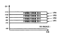
If should activate one specific among the external reader ESCR, then voltage generator changes its output voltage, and this realizes by power control signal VCC-CMD.STB CPU (at " CPU ") provides the identifier ID of target external reader ESCR, and according to predetermined scope (Fig. 7), this identifier is converted to the specific voltage level (selecting data SD) of power supply:
Any external reader ESCR of un-activation is corresponding to the standby voltage of+5V;
External reader ESCR with ID=1 and+7V and+voltage range VR1 between the 8V is associated;
External reader ESCR with ID=2 and+8V and+voltage range VR2 between the 9V is associated;
External reader ESCR with ID=3 and+9V and+voltage range VR3 between the 10V is associated;
And, the external reader ESCR with ID=4 and+10V and+voltage range VR4 between the 11V is associated.
For example, if activate and the corresponding external reader of ID=3 (it can be the ESCR3 in this structure), then control voltage CV and change into+9.2V (than the surplus of low value+0.2V) from+5V.If activate and the corresponding external reader of ID=1 (it can be ESCR1), then control voltage CV and change into+7.2V (than low value+0.2V surplus) from+5V.If forbid selected external reader, control voltage CV changes to+5V from actual value.Before voltage changes, the timing of the standard of following with clock signal that resets.
Because the quantity by the voltage range of the control voltage CV that power supply carried can link to each other with expansion bus reaching four intellignet card fetch ESCR.Because set-top box has usually+voltage of 12V, easily to external reader ESCR be provided at+5V and+voltage between the 11V.
(external reader ESCR Fig. 6) locates, and at first, the voltage that receives from STB (power supply) is regulated (voltage regulator), so that the control electronic circuit of the intelligent card interface in reader ESCR provides stable voltage in the smart card expansion.
Be set to unique value on the bus by the inside ID that is associated with this reader ESCR, pre-configured each expansion reader ESCR between its installation period.For example, this can realize by utilizing basic wire jumper.Measure input control voltage CV (voltage measurement), and compare, so that determine whether activate intellignet card fetch ESCR (ID comparator) with reference value.
If must activate reader ESCR, then enable signal is offered voltage variation detectors, otherwise, this signal indication disabled status.Also provide identical enable/disable signals, activate obtaining so that its preparation is used for clock and reset signal to the smart card standard interface.Enable/disable signals is also controlled clock adaption function (clock receiver line is adaptive), by add the adaptive clock bus of resistor between CLK+ and CLK-.
After the change in voltage at STB voltage generator place, provide clock (differential clocks driver) according to the form of difference.Difference scheme helps to reduce with the interference of other signals with because the caused problem of cable very much, and can utilize the twisted wire cable that speed up to 10MHz is provided.The differential transmitter input signal is expressed as CLK, and the differential clocks driver has produced positive clock signal CLK+ and negative clock signal CLK-:
When CLK is low level, be 1V at the CLK+ of transmitter output place voltage; When CLK is high level, be 5V at the CLK+ of transmitter output place voltage;
CLK be height at ordinary times, be 1V at the CLK-of transmitter output place voltage; When CLK was low level, the CLK-voltage of transmitter output place was 5V.
At smart card expansion reader ESCR place, then, the differential clocks receiver provides clearly clock (clean clock).It can provide:
When typically, during CLK+>[CLK-+200mV], be high level;
And when CLK+>[CLK--200mV], be low level.
Signal CLK+ and CLK-always positive voltage (with reference to " and "), and can have different bare maximums and can interference receiver.
Therefore, by between signal CLK+ and CLK-, comparing, provide differential received machine output voltage than input voltage (Fig. 8):
Among near CLK+=5V and CLK-=1V the less area E ND1, clock is a high level;
Among near CLK+=1V and CLK-=5V the less area E ND2, clock is a low level;
In the A0 of diagonal zone, its corresponding to:
200mV<[CLK+-CLK-]<+200mV, think that incorrect clock may take place to be received;
And more than the A0 of diagonal zone and among following the upper area A1 and lower area A2, it is possible (A1 zone: high level, A2 zone: low level) that correct clock receives respectively.
Determine the zone according to receiver voltage, described differential clocks bus is used for:
Exist information to offer STB smart card from expansion intellignet card fetch ESCR,
Between expansion intellignet card fetch ESCR and STB, provide bi-directional data.
STB clock transmitter output impedance on CLK+ and CLK-automatically is increased to about 100 Ω.In addition, come load signal by only utilizing basic resistor, can easily change clock CLK+/-voltage level.
The detection that 1/ smart card inserts
When smart card SC physics is present among the expansion reader ESCR (there is indicating device in smart card), if and expansion reader ESCR activates, then load clock bus by predetermined resistor (be positioned at CLK-, bus load is modulated, and CLK-is the maximum when going back the un-activation clock).
On the STB side, follow at integrator (there is interface in smart card) voltage comparator afterwards and check whether the CLK-voltage amplitude is lower than the threshold value TH1 of definition.In this case, and then smart card SC is identified as physics and is present in expansion reader ESCR place.
For example (Fig. 9 A) when being inserted in smart card SC among the remote reader ESCR, being in the signal CLK-amplitude of inserting more than the detection threshold TH1 (part 30) and reducing (part 31) along with the time, below this threshold value TH1 (part 32 to 34).(Fig. 9 B) like this, card insert detector and are converted to " card inserts " state (part 37) from " card takes out " state (part 36).When signal CLK-amplitude was increased to more than the threshold value TH1 (part 35) once more, card inserted detector and gets back to " card takes out " state (part 38).
2/ exchanges data between STB and reader ESCR
Exchanges data between STB and expansion reader ESCR is based on CLK+ and CLK-voltage-amplitude modulated.That is, to allow to detect data mode-bit duration bigger 372 times than the clock cycle for the data with the comparison of low state and high state, clock voltage and threshold value and integration.
This uses on both direction (from STB to reader ESCR, and opposite):
Utilize the CLK+ signal to carry out from STB to the transfer of data of expanding intellignet card fetch ESCR: the data transceiver among STB is according to the data by STB CPU (SCx-DATA-Out) output, produce the Data_out signal, and use these signals to change the amplitude of CLK+ signal by the voltage level modulating unit; In expansion reader ESCR side, data detector analysis and reference voltage data Vref_data[ESCR] the received CLK+ signal compared, and the data mode information that is obtained is sent to intelligent card interface;
Utilize the CLK-signal to realize from expanding the transfer of data of intellignet card fetch ESCR to STB: the bus load modulating unit receives data from intelligent card interface (SCx-DATA), and uses it to change the amplitude of CLK-signal; In the STB side, receive the CLK-signal by Data Detection, this detector is analyzed and reference voltage data Vref_data[STB] the CLK-signal compared, and the data mode information (SCx-DATA-In) that is obtained is sent to CPU.
Respectively CLK-and CLK+ voltage level and threshold value TH2 and TH3 are compared (be similar to smart card insert detect done like that) so that specified data is to be high level or low level:
If CLK+/-amplitude do not change, and then data are high level;
And, if CLK+/-amplitude reduces, and then data are low level.
And, only when card being inserted among the remote reader ESCR, can carry out exchanges data.In fact (Fig. 9 A), the TH2 threshold value is lower than the TH1 threshold value.Therefore, the CLK-signal shows exchanges data (amplitude is lower than TH2), has therefore only pointed out smart card insertion (amplitude is lower than TH1).
In the example shown, in the part 32 to 34 of CLK-signal, can carry out exchanges data, this is to be in " card inserts " state (part 37) because card inserts detector.Then, occurred: only the CLK-amplitude is lower than in the part 33 of TH2 threshold value therein, receives data by STB.
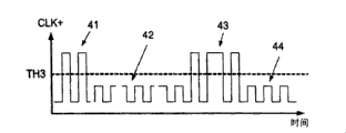
Correspondingly show the data that send to external reader ESCR (Figure 10 A and 10B) from STB, the amplitude of CLK+ on the TH3 threshold value (part 41) is reduced in time in this value (part 42) below threshold value, thereby the data detector of external reader ESCR is converted to low level state (part 46) from high level data state (part 45).Then, the CLK+ amplitude is increased to TH3 threshold value above (part 43) continuously, and is reduced to below the TH3 threshold value, thereby has caused the high data mode (part 47) and the low data mode (part 48) of data detector respectively.
More specifically, with the center that is illustrated as (Figure 11) of the realization mechanism on the exchanges data, obtain the amplitude modulation(PAM) of CLK+ and CLK-signal by three switching systems that formed branch breaking the bridge (dividing bridge).These switching systems have following feature respectively:
Be included in the external reader ESCR, and can be by resistor R ES1 with CLK-line link to each other with ground GND (corresponding to threshold value TH1, smart card detection);
Be included among the external reader ESCR, and can the CLK-line be linked to each other with ground GND by resistor R ES2 (corresponding to threshold value TH2, to the data transmission of STB);
And, be included among the STB, and can the CLK+ line be linked to each other with ground GND by resistor R ES3 (corresponding to threshold value TH3, to the data transmission of external reader ESCR).
3/ intellignet card fetch ESCR resets
Utilization changes the reset signal that produces smart card SC by the voltage of the power supply VCC (therefore being control voltage CV) of STB control.If dc voltage to change greater than 0.3V with less than 0.6V, has then produced the change of reset signal state: if this voltage is changed into increase, then forbidden and resetted, and if voltage to change be to reduce, then activated to reset.In addition, the voltage greater than 0.6V changes any change that (this is the situation during ESCR ID selects) do not cause reset mode.
As example (Figure 12), control voltage CV in time according to changing 50.At first, this voltage CV is in standby voltage level 5V (part 51), then, it is increased to the voltage between 8V and the 9V and approaches 8V (increasing step 52), corresponding to the external reader ESCR with ID=2.Therefore, activate this reader, and reset and activate.After this (increase step 53), the control voltage CV that still is lower than 9V has been left in positive voltage change included between 0.3V and 0.6V.Therefore, forbidding resets, and still selects identical reader ESCR2 simultaneously.Then, the control voltage CV that is higher than 8V has been left in included negative voltage change (reducing step 54) between 0.3V and 0.6V.Therefore, enabled and resetted.At last, control voltage CV reduces back standby voltage level 5V (reducing step 55), thereby has forbidden the reader ESCR with ID=2.
4/ intellignet card fetch software administration
The STB install software can be configured to down parameter, and it must carry out before any outside intelligent card reader uses:
The quantity of the inner intellignet card fetch ISCR of STB,
The quantity of STB external smart card reader ESCR,
At the defined encryption standard of each reader SCR;
And, the unique ID that is distributed for each external reader ESCR (here, nearly 4).
The example that such STB installs the SW menu comprises (Figure 13):
Intellignet card fetch is subsequently determined menu step 62,
Inside STB intellignet card fetch ISCR configuration menu step 63 subsequently, relate to two steps 64 and 65, respectively about each encryption standard (in given standard 66, for example famous Viaccess, Conax and Betacrypt) of the quantity of internal reader ISCR and its
Outside STB intellignet card fetch ISCR configuration menu step 73 subsequently, relate to three steps 74,75 and 77,, respectively about the quantity of external reader ESCR, its each encryption standard (in given standard 76, for example famous Viaccess, Conax and Betacrypt).And the ESCR ID in the set of the possible ID between 1 and 4 distributes.
Claims (15)
1. be used for the control appliance (1) of smart card fetch equipment, comprise:
Be used for the device (11) that communicates with at least two smart card fetch equipments (ESCR),
Be used for handling the device (12) of the information that receives from described smart card fetch equipment (ESCR),
And, be used to activate at least one described smart card fetch equipment (ESCR) and carry out current communicating devices (13),
It is characterized in that: described active device (13) is used for sending selection data (SD) to all described smart card fetch equipments (ESCR), and described selection data (SD) determine whether to select one of described smart card fetch equipment (ESCR) to carry out current communication.
2. control appliance according to claim 1 (1), it is characterized in that: at least one control voltage (CV) that described active device (13) is used for can be used for described smart card fetch equipment (ESCR) is with the data that elect (SD), and each described smart card fetch equipment (ESCR) is associated with the given range (VRi) of described control voltage (CV).
3. control appliance according to claim 2 (1) is characterized in that: described control appliance (1) is used for providing power supply to described smart card fetch equipment (ESCR), and described voltage has carried described control voltage (CV).
4. according to claim 2 or 3 described control appliances (1), it is characterized in that: described control appliance (1) comprises by be controlled at the device that resets (19) in the described smart card fetch equipment (ESCR) to described smart card fetch equipment (ESCR) transmission reset signal, described resetting means (19) is used for by causing that given voltage in described voltage range (VRi) changes the change with the reset mode that specifies in the smart card fetch equipment (ESCRi) that is associated with described voltage range (VRi) respectively, uses described control voltage (CV) control that resets.
5. according to claim 2 or 3 described control appliances (1), it is characterized in that: described active device (13) is used for sending on a plurality of selection communication paths of the quantity that is lower than described smart card fetch equipment (ESCR) selects data (SD), thereby at least one the described smart card fetch equipment (ESCR1) that receives described selection data (SD) by at least one described selection communication path is used for that (ESCR2 ESCR3) transmits the described selection data (SD) that receive to another described smart card fetch equipment at least respectively.
6. according to claim 2 or 3 described control appliances (1), it is characterized in that described equipment comprises and be used for associated apparatus (14) that described smart card fetch equipment (2) is associated with given function respectively.
7. according to claim 2 or 3 described control appliances (1), it is characterized in that: it is characterized in that in the decryption method of appointment and bank's method, selecting described function.
8. according to claim 2 or 3 described control appliances (1), it is characterized in that described control appliance comprises and be used for providing differential transfer clock signal (CLK+, device CLK-) to described smart card fetch equipment (ESCR).
9. according to claim 2 or 3 described control appliances (1), it is characterized in that described control appliance is used for providing (the CLK+ of the clock signal with at least one amplitude by at least one clock path to described smart card fetch equipment (ESCR), CLK-), described control appliance (1) comprises the device (16) that transmits data by at least one described clock path to described smart card fetch equipment (ESCR), described data transmission device (16) is used for having than the transfer of data threshold value (TH2 that is lower than described clock amplitude by using on described clock path, TH3) data-signal of lower amplitude specifies on the described clock path transfer of data to described fetch equipment (ESCR).
10. according to claim 2 or 3 described control appliances (1), it is characterized in that described control appliance is used for by at least one clock path, send clock signal (CLK+ with at least one amplitude to described smart card fetch equipment (ESCR), CLK-), described control device (1) comprises by receiving detection signal via described clock path from described smart card fetch equipment (ESCR), detects the device (18) of the existence of the smart card (SC) that is associated with described smart card fetch equipment (ESCR).
11. control appliance according to claim 10 (1), it is characterized in that: described control appliance (1) comprises via being used for receiving the device (17) of the described clock path of described detection signal from described smart card fetch equipment (ESCR) reception data, described checkout gear (18) and data sink (17) can compare with card detection threshold (TH1) and Data Receiving threshold value (TH2) respectively by the amplitude of the signal that will receive via described clock path, are identified in detection that receives and data-signal on the described clock path respectively.
12. set-top box (STB) is characterized in that it comprises and meets any described control appliance (1) of claim 1 to 3.
13. set-top box according to claim 12 (STB) is characterized in that: described set-top box comprises at least one output Connection Element (C-OUT), is respectively arranged with four communication point (Pj), is respectively applied for:
Output ground signalling (GND);
Export positive clock signal (CLK+);
Output negative clock signal (CLK-);
And out-put supply, fetch equipment activation and reset signal (VCC).
14. set-top box according to claim 13 (STB) is characterized in that: described Connection Element (C-OUT) is:
The communication point (P3) that is used to export negative clock signal (CLK-) also be provided for and the relevant input detection signal of existence of the smart card (SC) that is associated of described smart card fetch equipment (ESCR), and be used to import the Data Detection signal;
And the communication point (P2) that is used to export positive clock signal (CLK+) also is provided for the dateout transmission signals.
15. daisy chain comprises meeting described at least one set-top box of claim 12 (STB) and at least two smart card fetch equipments (ESCR1, ESCR2, ESCR3).
Applications Claiming Priority (2)
| Application Number | Priority Date | Filing Date | Title |
|---|---|---|---|
| EP03292128A EP1511313A1 (en) | 2003-08-29 | 2003-08-29 | Control device, smart card reading activation device and associated products |
| EP03292128.0 | 2003-08-29 |
Publications (2)
| Publication Number | Publication Date |
|---|---|
| CN1592353A CN1592353A (en) | 2005-03-09 |
| CN100518237C true CN100518237C (en) | 2009-07-22 |
Family
ID=34089762
Family Applications (1)
| Application Number | Title | Priority Date | Filing Date |
|---|---|---|---|
| CNB2004100576718A Expired - Fee Related CN100518237C (en) | 2003-08-29 | 2004-08-23 | Control device, smart card reading activation device and associated products |
Country Status (7)
| Country | Link |
|---|---|
| US (1) | US8561120B2 (en) |
| EP (1) | EP1511313A1 (en) |
| JP (1) | JP4681837B2 (en) |
| KR (1) | KR101096682B1 (en) |
| CN (1) | CN100518237C (en) |
| DE (1) | DE602004018880D1 (en) |
| MX (1) | MXPA04008337A (en) |
Families Citing this family (16)
| Publication number | Priority date | Publication date | Assignee | Title |
|---|---|---|---|---|
| US7726566B2 (en) * | 2005-04-15 | 2010-06-01 | Research In Motion Limited | Controlling connectivity of a wireless smart card reader |
| JP4702931B2 (en) * | 2005-05-16 | 2011-06-15 | Necトーキン株式会社 | Non-contact IC tag communication device and non-contact IC tag communication system using reader / writer for contact IC tag |
| EP1793322A1 (en) * | 2005-11-30 | 2007-06-06 | Nagracard S.A. | Adaptable security module |
| JP4714852B2 (en) * | 2006-04-28 | 2011-06-29 | 日本電産サンキョー株式会社 | Medium processing system and mediation medium processing apparatus |
| US7464195B2 (en) * | 2006-05-22 | 2008-12-09 | International Business Machines Corporation | Method and apparatus for detecting a presence of a device |
| WO2009001797A1 (en) * | 2007-06-25 | 2008-12-31 | B.U.G., Inc. | Reader/writer system and its control method |
| US8887220B2 (en) * | 2008-07-25 | 2014-11-11 | At&T Intellectual Property I, L.P. | Network interface devices |
| CN101639897B (en) * | 2009-08-31 | 2011-08-17 | 北京飞天诚信科技有限公司 | Method, device and system of operating overrange frequency conversion factor smart card |
| KR20130029044A (en) | 2010-02-25 | 2013-03-21 | 톰슨 라이센싱 | Miniature multilayer radiative cooling case with hidden quick release snaps |
| BR112013022150B1 (en) | 2011-03-09 | 2022-06-21 | Interdigital Ce Patent Holdings | electronic device |
| JP5792386B2 (en) | 2011-07-14 | 2015-10-14 | トムソン ライセンシングThomson Licensing | Set-top box with snap-in heat sink and smart card reader with heat sink retention fastener |
| JP6130844B2 (en) | 2011-10-19 | 2017-05-17 | トムソン ライセンシングThomson Licensing | Remote control with feedback for blind navigation |
| CN102984581B (en) * | 2012-12-12 | 2015-08-05 | 青岛海信宽带多媒体技术有限公司 | A kind of set-top-box system and Set Top Box detection method |
| CN103561321B (en) * | 2013-10-15 | 2017-01-18 | 深圳创维数字技术有限公司 | Method and device for preventing Android intelligent set top box from being abnormally upgraded |
| US11709522B1 (en) * | 2020-09-16 | 2023-07-25 | Xilinx, Inc. | Power and temperature driven clock throttling |
| CN112816810A (en) * | 2020-12-28 | 2021-05-18 | 国网北京市电力公司 | Data acquisition device and data acquisition method |
Family Cites Families (18)
| Publication number | Priority date | Publication date | Assignee | Title |
|---|---|---|---|---|
| JPS61157127A (en) | 1984-12-28 | 1986-07-16 | Hitachi Denshi Ltd | Multiple address radio transmission monitor system |
| JPH0664561B2 (en) | 1985-08-27 | 1994-08-22 | 日本電気株式会社 | Simultaneous writing circuit |
| JPH0658085B2 (en) | 1985-11-07 | 1994-08-03 | 日本電装株式会社 | Vehicle control device having failure diagnosis function |
| US5089793A (en) * | 1989-10-16 | 1992-02-18 | Seiko Epson Corporation | Semiconductor device having an oscillatory circuit |
| JP2830424B2 (en) | 1989-10-16 | 1998-12-02 | セイコーエプソン株式会社 | Semiconductor device |
| JPH05282067A (en) | 1992-03-30 | 1993-10-29 | Toshiba Corp | Operation clock generating device |
| JP3953153B2 (en) | 1997-09-18 | 2007-08-08 | 富士通株式会社 | Programmable gate array configuration method and programmable gate array device |
| GB2332314B (en) * | 1997-12-09 | 2001-05-16 | Sony Uk Ltd | Interface for a receiver and method of arrangement thereof |
| US6263392B1 (en) * | 1999-01-04 | 2001-07-17 | Mccauley Jack J. | Method and apparatus for interfacing multiple peripheral devices to a host computer |
| AU3631000A (en) * | 1999-03-30 | 2000-10-16 | Sony Electronics Inc. | System for interfacing multiple conditional access devices |
| US6978335B2 (en) * | 2000-06-30 | 2005-12-20 | 02Micro International Limited | Smart card virtual hub |
| US6694399B1 (en) * | 2000-09-14 | 2004-02-17 | Schlumberger Malco, Inc. | Method and device for universal serial bus smart card traffic signaling |
| US20020087968A1 (en) * | 2001-01-02 | 2002-07-04 | Aditya Krishnan | Set-top box with credit card reader and method of activation/authentication |
| US6753758B2 (en) * | 2001-01-03 | 2004-06-22 | Gerald Adolph Colman | System and method for switching voltage |
| DE10127124A1 (en) * | 2001-06-05 | 2002-12-19 | Sc Itec Gmbh | Electronic circuit for chip card interfaces has communication device switched between alternate chip card interfaces with selective activation of corresponding analogue interface |
| CN1643896A (en) * | 2002-03-22 | 2005-07-20 | 皇家飞利浦电子股份有限公司 | Modular set top box |
| US7152127B1 (en) * | 2002-10-07 | 2006-12-19 | Flextronics Sales And Marketing (A-P) Ltd. | Multi-purpose peripheral interface for computing systems |
| US20060027654A1 (en) * | 2004-08-04 | 2006-02-09 | Chi-Tung Chang | Card reader and data transmission method therefor |
-
2003
- 2003-08-29 EP EP03292128A patent/EP1511313A1/en not_active Withdrawn
-
2004
- 2004-08-23 CN CNB2004100576718A patent/CN100518237C/en not_active Expired - Fee Related
- 2004-08-25 DE DE602004018880T patent/DE602004018880D1/en active Active
- 2004-08-26 US US10/926,613 patent/US8561120B2/en not_active Expired - Fee Related
- 2004-08-27 KR KR1020040067827A patent/KR101096682B1/en not_active IP Right Cessation
- 2004-08-27 MX MXPA04008337A patent/MXPA04008337A/en active IP Right Grant
- 2004-08-27 JP JP2004248922A patent/JP4681837B2/en not_active Expired - Fee Related
Also Published As
| Publication number | Publication date |
|---|---|
| MXPA04008337A (en) | 2005-06-08 |
| DE602004018880D1 (en) | 2009-02-26 |
| KR101096682B1 (en) | 2011-12-22 |
| US20060059503A1 (en) | 2006-03-16 |
| CN1592353A (en) | 2005-03-09 |
| US8561120B2 (en) | 2013-10-15 |
| JP2005078642A (en) | 2005-03-24 |
| JP4681837B2 (en) | 2011-05-11 |
| EP1511313A1 (en) | 2005-03-02 |
| KR20050021889A (en) | 2005-03-07 |
Similar Documents
| Publication | Publication Date | Title |
|---|---|---|
| CN100518237C (en) | Control device, smart card reading activation device and associated products | |
| US6786418B1 (en) | Smart card customizing system | |
| CN101154118B (en) | Clock signal generator for USB device | |
| KR101223986B1 (en) | Smart card and smart card system supporting plurality of interfaces | |
| US10244372B2 (en) | Method and device for managing information exchange between a main element, for example a NFC controller, and a set of at least two auxiliary elements | |
| JP6022766B2 (en) | Multi-interface memory card and its operation method | |
| US20120228390A1 (en) | Multi-application contactless smart card | |
| MXPA03002250A (en) | Method and device for universal serial bus smart card traffic signaling. | |
| US20180032850A1 (en) | Magnetic secure transmission device, electronic device and mobile system including the same | |
| CN101238478A (en) | Data communication system, device for executing ic card function, control method for the device, and information processing terminal | |
| CN105160282B (en) | Unit-type sclection system and Unit-type sclection method and household electrical appliance | |
| US20090287864A1 (en) | Electronic module for programming chip cards comprising contacts | |
| CN109658545A (en) | A kind of cipher set-up method and network access system of network lock | |
| CN103399649A (en) | Data processing method based on K virtual machine (KVM) and KVM transmitting device | |
| CA2420207C (en) | Multiport card | |
| US20080244279A1 (en) | Methods and Apparatus to Detect Voltage Class of a Circuit | |
| US11170360B2 (en) | Magnetic secure transmission (MST) device, MST system and controller including the same | |
| CN108877185A (en) | A kind of Bluetooth remote control method and circuit | |
| KR101803286B1 (en) | Smartcard Interface Conversion Device, Embedded system having the same device and Method used in the same device | |
| EP1511314B1 (en) | System and method for smart card reader activation | |
| JP4097708B2 (en) | Transponders created for contactless inductive communications | |
| ES2213702T3 (en) | COMMUNICATION CONTROL IN ACCESS CONTROL SYSTEMS AND INPUT CONTROL SYSTEMS. | |
| CN107645679B (en) | Production method and system of card-free condition receiving system of set top box | |
| US6408077B1 (en) | Descrambling device of a security element and security element comprising such a device | |
| CN105224239A (en) | A kind of flash storer and storage system |
Legal Events
| Date | Code | Title | Description |
|---|---|---|---|
| C06 | Publication | ||
| PB01 | Publication | ||
| C10 | Entry into substantive examination | ||
| SE01 | Entry into force of request for substantive examination | ||
| C14 | Grant of patent or utility model | ||
| GR01 | Patent grant | ||
| C17 | Cessation of patent right | ||
| CF01 | Termination of patent right due to non-payment of annual fee |
Granted publication date: 20090722 Termination date: 20120823 |