CN100512704C - Metallic slide fastener element and method for manufacturing the same - Google Patents
Metallic slide fastener element and method for manufacturing the same Download PDFInfo
- Publication number
- CN100512704C CN100512704C CNB2005100528437A CN200510052843A CN100512704C CN 100512704 C CN100512704 C CN 100512704C CN B2005100528437 A CNB2005100528437 A CN B2005100528437A CN 200510052843 A CN200510052843 A CN 200510052843A CN 100512704 C CN100512704 C CN 100512704C
- Authority
- CN
- China
- Prior art keywords
- shear
- cutting
- mould
- slide fastener
- shank
- Prior art date
- Legal status (The legal status is an assumption and is not a legal conclusion. Google has not performed a legal analysis and makes no representation as to the accuracy of the status listed.)
- Active
Links
Images


Classifications
-
- A—HUMAN NECESSITIES
- A44—HABERDASHERY; JEWELLERY
- A44B—BUTTONS, PINS, BUCKLES, SLIDE FASTENERS, OR THE LIKE
- A44B19/00—Slide fasteners
- A44B19/02—Slide fasteners with a series of separate interlocking members secured to each stringer tape
- A44B19/04—Stringers arranged edge-to-edge when fastened, e.g. abutting stringers
- A44B19/06—Stringers arranged edge-to-edge when fastened, e.g. abutting stringers with substantially rectangular members having interlocking projections and pieces
-
- E—FIXED CONSTRUCTIONS
- E02—HYDRAULIC ENGINEERING; FOUNDATIONS; SOIL SHIFTING
- E02B—HYDRAULIC ENGINEERING
- E02B3/00—Engineering works in connection with control or use of streams, rivers, coasts, or other marine sites; Sealings or joints for engineering works in general
- E02B3/04—Structures or apparatus for, or methods of, protecting banks, coasts, or harbours
- E02B3/12—Revetment of banks, dams, watercourses, or the like, e.g. the sea-floor
- E02B3/14—Preformed blocks or slabs for forming essentially continuous surfaces; Arrangements thereof
-
- A—HUMAN NECESSITIES
- A01—AGRICULTURE; FORESTRY; ANIMAL HUSBANDRY; HUNTING; TRAPPING; FISHING
- A01G—HORTICULTURE; CULTIVATION OF VEGETABLES, FLOWERS, RICE, FRUIT, VINES, HOPS OR SEAWEED; FORESTRY; WATERING
- A01G9/00—Cultivation in receptacles, forcing-frames or greenhouses; Edging for beds, lawn or the like
- A01G9/02—Receptacles, e.g. flower-pots or boxes; Glasses for cultivating flowers
-
- B—PERFORMING OPERATIONS; TRANSPORTING
- B21—MECHANICAL METAL-WORKING WITHOUT ESSENTIALLY REMOVING MATERIAL; PUNCHING METAL
- B21D—WORKING OR PROCESSING OF SHEET METAL OR METAL TUBES, RODS OR PROFILES WITHOUT ESSENTIALLY REMOVING MATERIAL; PUNCHING METAL
- B21D53/00—Making other particular articles
- B21D53/46—Making other particular articles haberdashery, e.g. buckles, combs; pronged fasteners, e.g. staples
- B21D53/50—Making other particular articles haberdashery, e.g. buckles, combs; pronged fasteners, e.g. staples metal slide-fastener parts
- B21D53/52—Making other particular articles haberdashery, e.g. buckles, combs; pronged fasteners, e.g. staples metal slide-fastener parts fastener elements; Attaching such elements so far as this procedure is combined with the process for making the elements
-
- E—FIXED CONSTRUCTIONS
- E02—HYDRAULIC ENGINEERING; FOUNDATIONS; SOIL SHIFTING
- E02D—FOUNDATIONS; EXCAVATIONS; EMBANKMENTS; UNDERGROUND OR UNDERWATER STRUCTURES
- E02D17/00—Excavations; Bordering of excavations; Making embankments
- E02D17/20—Securing of slopes or inclines
- E02D17/205—Securing of slopes or inclines with modular blocks, e.g. pre-fabricated
-
- E—FIXED CONSTRUCTIONS
- E02—HYDRAULIC ENGINEERING; FOUNDATIONS; SOIL SHIFTING
- E02D—FOUNDATIONS; EXCAVATIONS; EMBANKMENTS; UNDERGROUND OR UNDERWATER STRUCTURES
- E02D2600/00—Miscellaneous
- E02D2600/20—Miscellaneous comprising details of connection between elements
-
- Y—GENERAL TAGGING OF NEW TECHNOLOGICAL DEVELOPMENTS; GENERAL TAGGING OF CROSS-SECTIONAL TECHNOLOGIES SPANNING OVER SEVERAL SECTIONS OF THE IPC; TECHNICAL SUBJECTS COVERED BY FORMER USPC CROSS-REFERENCE ART COLLECTIONS [XRACs] AND DIGESTS
- Y10—TECHNICAL SUBJECTS COVERED BY FORMER USPC
- Y10T—TECHNICAL SUBJECTS COVERED BY FORMER US CLASSIFICATION
- Y10T24/00—Buckles, buttons, clasps, etc.
- Y10T24/25—Zipper or required component thereof
- Y10T24/2539—Interlocking surface constructed from plural elements in series
- Y10T24/2543—Interlocking surface constructed from plural elements in series with element structural feature unrelated to interlocking or securing portion
-
- Y—GENERAL TAGGING OF NEW TECHNOLOGICAL DEVELOPMENTS; GENERAL TAGGING OF CROSS-SECTIONAL TECHNOLOGIES SPANNING OVER SEVERAL SECTIONS OF THE IPC; TECHNICAL SUBJECTS COVERED BY FORMER USPC CROSS-REFERENCE ART COLLECTIONS [XRACs] AND DIGESTS
- Y10—TECHNICAL SUBJECTS COVERED BY FORMER USPC
- Y10T—TECHNICAL SUBJECTS COVERED BY FORMER US CLASSIFICATION
- Y10T24/00—Buckles, buttons, clasps, etc.
- Y10T24/25—Zipper or required component thereof
- Y10T24/2539—Interlocking surface constructed from plural elements in series
- Y10T24/2557—Interlocking surface constructed from plural elements in series having mounting portion with specific shape or structure
- Y10T24/2559—Interlocking surface constructed from plural elements in series having mounting portion with specific shape or structure including embracing jaws
Abstract
A metallic slide fastener element in which an exposed portion outside of an element is finished uniformly with a high smoothness and the fixing strength to a fastener tape is intensified, and a method for effectively manufacturing the same element, wherein a metallic flat type wire rod is placed on a die and the flat type wire rod is punched out with a punch so as to produce a slide fastener element, and at this time, a mouth on a punch side of the die or a peripheral edge of the die is chamfered at a radius of 0.01 to 1.0 mm and a clearance between the punch and the die is set to 0 to 30 mum, so that an element, which has a cut surface comprising a shear surface of 80% or more and a fracture surface of less than 20% and is suitable as a slide fastener to be attached to a high quality product, is obtained.
Description
Technical field
The present invention relates to a kind of by the metal thread bar of punching press platypelloid type zipper components of making and the method for making this zipper components.
Background technology
Usually make the metal parts of slide fastener according to following two typical manufacture methods, a left side and right shank that this part comprises a connector and separately extends as two branches from this head in same level.According to a method in these methods, the long filament rod with a Y shape section is flat by the multiple working procedure roller, then along this rod vertically with a required thickness this rod of sectility successively so that obtain a Y shape part material.By making a part of local deformation corresponding to this material of connector under pressure to form mate and to have made all parts.Will by all parts of this method manufacturing with etc. pitch be implanted in successively on the side of long zipper strip of independent loading, so that make a slide fastener continuously.
According to other method, successively platypelloid type silk rod is struck out the shape of a part by using mould and drift, and make its plastic deformation under pressure, so that form connector, individually produce many parts thus.After the part with this method manufacturing stands tumbling or chemical polishing, along a side of zipper strip with etc. pitch transplant them successively so that make continuous slide fastener.In the part made from a kind of method in back, because mould and drift can form multiple shape, so the appearance of the connector of this part and structure are extensive especially.In the simplest shape of connector, a side of the middle body of the connector that is combined to form by trapezoidal and rectangle is recessed into, and the outstanding mate with chevron constitutes opposite side simultaneously.On the other hand, for example in Japanese Patent Application Publication thing 59-10858 (patent documentation 1), Japanese Patent Application Publication thing 59-10859 (patent documentation 2), Japanese utility model application publication 1-80012 (patent documentation 3) etc., disclosed other typical structure.
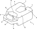
Fig. 1 illustrates in these patent documentations 1 to 3 typical shape and the structure of the part that discloses, obtain by punching press platypelloid type silk rod, and this part comprises a connector 2 and a left side and right shank 4.Connector 2 comprise one have shank 4 thickness 1/3 thickness plate part 8, as on the preceding and back of plate part substantially central authorities expand all mates of all bossings 3 and with the same level of the shank of plate part 8 on extend in all recessed portions (fitting concaveportion) 6 that cooperates that form in the planar section so that respectively cooperate recessed portion to center on the side surface on the leg side of bossing 3 and have predetermined gap.The part of one bossing 3 of one counterpart is assemblied in and cooperates between recessed portion 6 and the bossing 3, and all parts are meshing with each other.In addition, this part also comprise be arranged on a left side and the front end place of right shank 4 and extend into the mutual close tight part 7 of holding under the arm.
Simultaneously, have therein one by the above-mentioned metal thread bar of the flat Y shape section of roller be cut, then in the metal parts of the mate by the molded connector of punching press, because the left side of resulting part and the outer surface of right shank and connector are put down by roller, so on the processed surface of this part, be not formed with ropy surface, so that obtain even curface on the whole.But,, when cutting with drift and going out this part, on the cutting surface, produce part and the breaking portion that is sheared usually for the metal parts that is called single part that in patent documentation 1 to 3, is disclosed.Formed extremely flat shear surface in cutting out section, breaking portion has bigger roughness, forms the tiny unevenness of the flaw that comprises the picture scratch in the part of breaking portion.In being connected in the slide fastener of high quality of products, often use the metal parts that is called single part.Thus, in the situation of this single part, in being implanted in zipper strip after the outside exposed surface of this part need be repaired accurately.
In addition, in order to repair after producing part material by using mould and drift to go out metal flat flat pattern silk rod as previously discussed, this class part is carried out tumbling or chemical polishing, often increased the roughness of bursting surface simultaneously by this polishing action.For this reason, as the product after the finishing, the difference between shear surface and bursting surface becomes more obvious.Thus, therein this part is implanted in the slide fastener in the zipper strip (fastener tape), especially the surface of the exposed parts of this part, promptly the outer surface of a left side and the outer surface of right shank and connector looks finishing equably of picture.For the slide fastener that is connected in high quality of products, this can be serious defective.
On the other hand, for this metalloid part is fixed in slide fastener, holds heart yearn (core thread) part that tightly on a side of zipper strip, forms under the arm and compress a left side and right shank securely by a left side and right shank.This moment constant intensity depend on a left side and the front end of right shank hold under the arm tight part engagement enter zipper strip quantity and to heart yearn partly hold tight intensity under the arm.According to this viewpoint, the higher roughness of the interior perimeter surface of each shank of left and right shank is preferable.
Summary of the invention
Finished the present invention for solving the problems referred to above that may in the traditional zipper spare that is called single part, take place, the purpose of this invention is to provide a kind ofly, also provide a kind of and have for the metal parts of the high constant intensity of a zipper strip and the method that a kind of this part of effective manufacturing is used to its metal parts finishing, that have high-flatness that carries out exposed surface equably.
(slide fastener element) realized this purpose by a kind of zipper components, this zipper components has the basic structure of metal zip fastener part of the present invention, it obtains by punching press platypelloid type screw mandrel, wherein at least one cutting surface of a side surface area comprises the left side of connector and the outer circumferential side surface of right flank and a left side and right shank, from the plane, this at least one cutting surface have more than 80% shear surface and less than 20% bursting surface.Can be reliably and make this metal parts effectively according to making a kind of method that zipper components uses, wherein a platypelloid type metal thread bar is arranged on the mould, with this platypelloid type silk rod of a drift punching press.The characteristics of this method are: the aperture on the punching press side of mould or the periphery of mould are with 0.01 to 1.0 millimeter radius rounding, and the gap between mould and drift is 0 to 30 micron.
Just the average surface roughness Ra of the lip-deep shear surface of cutting of part material is preferably 1.0a or following after punching press, and the average surface roughness of this shear surface is preferably 0.5a or following.In addition, preferably the cutting surface at least one inboard of the shank of zipper components has the shear surface less than 80%, and remainder is a bursting surface simultaneously.More preferably, the cutting surface on the inboard of shank is made of the shear surface less than 50%.
According to above-mentioned manufacture method, more preferably the gap between mould and drift (T) is 0.1 to 10 micron, and the thickness (t) of the gap between mould and drift (T) and platypelloid type silk rod preferably satisfies following equation (I):
0<T/t≤0.001......(I)
According to single part of the present invention, because form by punching press it the cutting surface by 80% or above shear surface constitute, so the smooth degree that a connector and a left side and the outer surface that exposes of right shank is had improve, thereby satisfied requirement about the slide fastener that especially puts on high quality of products.In order to reach this smooth degree, preferably adopt above-mentioned manufacture method of the present invention, and, if the gap between mould and drift is set to 0.1 to 10 micron, so 90% or above cutting surface can constitute by shear surface.
When observing the cutting surface of metal, shear surface and bursting surface co-exist on this cutting surface usually.About shear surface and bursting surface, if light is radiated at the cutting surface with predetermined angle of inclination and upward and from a just relative position of departing from it observes relevant situation, shear surface is because reflected illumination light regularly and on the contrary, so show as aterrimus, thus bursting surface because brokenly reflected illumination light show as be seemingly white.According to the present invention, like this structure cutting surface, so that when the cutting of observing this part that obtains by punching press platypelloid type silk rod is surperficial, the area in the zone that aterrimus the is occupied zone occupied with respect to white be 80% or more than.When 80% or above cutting surface when being made of shear surface, this surperficial smooth degree is higher, thereby has produced with high accuracy high-quality part evenly processing and that have fabulous outward appearance.If this ratio be 90% or more than, bursting surface is almost eliminated, thus it is splendid at the outward appearance design aspect, can have the product of higher-value to be used for the product of a high-quality brand as one.Can be reliably and make this part effectively about the method for manufacturing zipper components of the present invention, thus the shearing table area improved to cutting the ratio on surface.
Simultaneously, in the part material that obtains by punching press platypelloid type silk rod, if do not carry out any specific processing, on the edge line part, produce because the formed burr of this material of cutting, therefore, this material require is by specific processing, and for example tumbling or chemistry throwingization are so that obtain final products.At this moment, the shear surface that produces when punching press finally is damaged owing to the friction of grinding stone powder, the relatively shared ratio decline of shear surface during with punching press.However, in order to obtain having 80% or the above-mentioned part of above shear surface, the average surface roughness Ra of the shear surface in the cutting surface need be 1.0a or following.If plan to obtain to have 90% or the part of above shearing table area, this average surface roughness Ra need be 0.5a or following.
On the other hand, the cutting surface on the inboard of the shank of above-mentioned part is the part that will be connected in zipper strip at least, strains at chain belt so that hold under the arm, and this part is not exposed to the outside after this part is connected in zipper strip.Therefore, the area that shear surface is in this section occupied is not so important, on the contrary, if the shared area of bursting surface increases, has strengthened the degree that is assemblied in zipper strip, thereby has increased constant intensity.Therefore, the shear surface of the inboard of shank shared area in the cutting surface is set to less than 80%, simultaneously the shared area of bursting surface be set to 20% or more than.In order further to strengthen constant intensity, preferably the bursting surface area is set at 50% or more than.
In order to obtain this cutting surface, the gap T between mould and the drift is set in 0 to 30 micron the scope, the aperture on the punching press side of mould or the periphery of mould are provided with the nose circle of radius R.By this R being set at 0.01 to 1.0 millimeter, prevent from platypelloid type silk rod, to produce the crack, be 80% or above zipper components with regard to having obtained shear surface wherein with respect to the ratio of bursting surface.
In addition, satisfy aforesaid equation (I), just can improve the ratio of shear surface if the thickness t of gap T between mould and drift and platypelloid type silk rod is formed into.
Description of drawings
Fig. 1 is the outline drawing that an example of metal zip fastener spare of the present invention is shown.
Fig. 2 is the key diagram of a technology of many steps that this part is made in expression successively in same accompanying drawing.
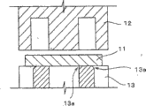
Fig. 3 schematically illustrates the drift that is used for manufacture method of the present invention and the longitudinal sectional view of mould device.
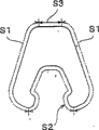
Fig. 4 is the plane that the peripheral cutting zone of this part schematically is shown.
The cutaway view of drift and mould when Fig. 5 is line " V-V " the intercepting part that is schematically illustrated in Fig. 2.
The cutaway view of drift and mould when Fig. 6 is line " VI-VI " the intercepting part that is schematically illustrated in Fig. 2.
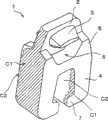
Fig. 7 is according to the stereogram part of one first embodiment of the present invention, that observe from the left side.
Fig. 8 is according to stereogram this part of first embodiment, that observe from the right side.
Fig. 9 is according to the stereogram part of one second embodiment of the present invention, that observe from the left side.
Figure 10 is according to stereogram this part of second embodiment, that observe from the right side.
Figure 11 is according to a stereogram traditional part of comparison example, that observe from the left side.
Figure 12 is the stereogram of observing from the right side of this tradition part.
Figure 13 is the partial plan layout that the slide fastener of part shown in Figure 1 is installed on it.
The specific embodiment
Hereinafter with reference to the preferred embodiment of the accompanying drawing narration metal zip fastener part that is called as independent part of the present invention with make the method that this part is used.In patent documentation 3, narrated part 1 of the present invention, it have as shown in Figure 1, above-described shape and structure.Have the shape identical with patent documentation 3 and the part 1 of structure though this paper has narrated, nature also can adopt shape and structure and other shape and the structure of the part of narrating in each document in patent documentation 1 and 2.
The metal parts 1 of this embodiment has the bossing 3 in the middle body of the preceding and rear surface of the thin flat plate part 8 of connector 2, and these two bossings are mate, and one is trapezoidal and a rectangular shape is combined in connector 2.Shape about each bossing 3, as shown in Figure 1, this bossing provides the profile of pyramid substantially, and than long, wherein the area of rectangular section reduces in the direction of leaving thin flat plate part 8 this pyramid gradually in plane at the width of part 1.And, divide a side of 4 that the one protrusion limit part 5 of U-shaped substantially is set at the left side of thin flat plate part 8 and right shank, should protrude limit part seemingly and surround bossing 3 with thickness, the band predetermined gap identical with shank 4.At bossing 3 with protrude and to form the cooperation recessed portion 6 of U-shaped substantially between the limit part 5, when as shown in figure 13 slide fastener 10 was among the engagement, the part of the bossing 3 of coupling part 1 was assemblied in this recessed portion.Extend a pair of shank 4 from the end face that protrudes limit part 5, so that they at grade and right-hand branch left.The thickness of left and right shank 4 and protrusion limit part 5 each comfortable vertical direction is three times of thin flat plate part 8 substantially.In addition, the tight part 7 of holding under the arm on an a pair of left side and the right side is set in the end of a left side and right shank 4, they extend to close mutually.
Produce one after the other and continuously the stamping products (part material 1 ') of part 1 with this shape and structure by the multiple tracks punch process from platypelloid type silk rod 11 shown in Figure 2.Platypelloid type silk rod 11 is transported to the right side discontinuously from the left side in same figure, and carries out punch process in the dead time.The thickness of this platypelloid type silk rod 11 equals a left side and right shank 4 and protrudes limit part 5 thickness separately.In one first punch process (A),, as shown in same figure (A), in platypelloid type silk rod 11, form a connector area E by the molding die (not shown) dashed area of punching press platypelloid type silk rod 11 from the top down.In this connector area E, form bossing 3 and thin flat plate part 8 and cooperate recessed portion 6 by punching press.
In one second punch process shown in (B) of Fig. 2, by having with the mould of the indicated shape of hatching and drift to the punching press of hacures portion, and have a connector area E, stayed U-shaped protrusion limit part 5 and a left side and right shank 4 substantially, thereby the shape in the 3rd step (C) at one shown in Fig. 2 is provided.Secondly, use, therefore obtained the part material 1 ' shown in (D) of Fig. 2 with required form by the remainder punching press of the indicated mould of (C) section line of Fig. 2 and drift to the top of connector 2.This manufacturing process is not special for the present invention, but in the past performed technology.
In Fig. 3, schematically show characteristic according to manufacture method of the present invention.As shown in Figure 3, the size of the gap T that forms between drift 12 and mould 13 is main points for carrying out the present invention.In addition, the edge line part (shoulder) in the aperture of mould goes up and forms nose circle, is rounding, also is main points.According to this embodiment, above-mentioned T value is 0 to 30 micron, preferably in 0.1 to 10 micrometer range.If numerical value T is 0 micron, naturally, between drift and mould, produce collision, hinder steady punching press.If it be 30 microns or more than, bursting surface increases in stamping surface (cutting surface), consequently significantly drops under 80% for the shared ratio of shear surface of initial purpose of the present invention.Suitable value is in 0.1 to 10 micron scope.And, if the aperture of mould (shoulder) rounding is set in 0.01 to 1.0 millimeter with the radius R of nose circle.If this radius R be 0.01 millimeter or below, the bursting surface that is produced by the crack in the cutting surface of stamping products increases.If radius R be 1.0 millimeters or more than, cutting processing self can not be carried out reposefully, so that not only bursting surface increases, and cut end is often crooked or tilt.
As mentioned above, for the part 1 of this type, by the finishing processing of resulting part material 1 ' experience tumbling of punch process or chemical polishing.Because this polishing processing, the roughness on the cutting surface of part material 1 ' can become more coarse.For this reason, for the shear surface of the part 1 that makes the finishing that forms characteristic of the present invention be 80% or more than, the surface is cut in wideer the cutting of value that needs to form than when the stage of part material 1 '.At this moment the factor that influences shear surface is the surface roughness Ra in the cutting surface of part material 1 '.According to this embodiment, average surface roughness Ra is set to 1.0a or following, preferably it is set to 0.5a or following.This numerical value can make after polishing processing subsequently in part 1 shear surface account for the surperficial ratio of cutting to reach 80%, preferably arrive 90%.
According to this embodiment, about all cutting surfaces of part material 1 ', shear surface with respect to the ratio of bursting surface be not set at 80% or more than.Fig. 4 pointed out in part 1, to have 80% or the region S 2 of above shear surface between the border.In Fig. 4 with the region representation of symbol S3 indication when part engages, be not exposed to the outside, be hidden in the part between the engaging elements, if possible, preferably region S 1 afterwards the shear surface of region S 3 be set in 80% or more than.That is to say that in part shown in Figure 41, the outer circumferential side surface of the left side of connector 2 and right flank and a left side and right shank 4 is region S 1, interior all side surfaces of a left side and right shank 4 are S2 simultaneously.All the other tops of connector 2 are region S 3.
In order to form circumferential lateral surface region S 1 and connector top surface S3, as shown in Figure 5, between drift 12 and mould 13, form gap T with above-mentioned preliminary dimension, this constitutes characteristic of the present invention, by the radius R of being determined by predetermined value edge line part (shoulder) rounding to the aperture of mould 13.Its result, in the cutting surface in region S 1 and S3 the ratio of shear surface can be 80% or more than.The interior side surface area S2 that uses about a left side and right shank 4, as shown in Figure 6, set for traditional measure-alike or bigger than conventional size on the above-mentioned size specific in the size of the gap T that forms between drift 12 and the mould 13 according to the present invention, and the aperture of mould 13 (shoulder) 13a rounding not.Perhaps, if the size of gap T has surpassed the specific above-mentioned size according to the present invention, the ratio of shear surface descends sharp, so that the ratio of bursting surface surpasses 50%.
In addition, if the size of the gap T that forms in a left side and interior all side regions of right shank 4, between drift 12 and mould 13 is set at the rounding not by aperture (shoulder) 13a of specific above-mentioned size of the present invention and mould 13, the ratio of shear surface rises so, but it is difficult to surpass 80%.From this fact, be understood that in order to make part 1 of the present invention, satisfy the gap T of the above-mentioned value among the present invention and be indispensable by the radius R rounding.By being formed on the region S 2 that has many bursting surfaces in a left side and the interior perimeter surface of right shank 4, the joint that enters the above-mentioned side of the zipper strip 9 that comprises heart yearn part 10 increases, thus can be strong fix.
In addition, according to preferred embodiment, the gap T (micron) between drift 12 and mould 13 and the thickness t (millimeter) of platypelloid type silk rod need satisfy following equation (I).
0<Y/t≤0.001......(I)
If the thickness t of gap T and platypelloid type silk rod satisfies equation (1), the increasing of shear surface with regard to ratio.
Secondly, will by with the relatively narration specific examples of the present invention of conventional example.
(example)
The gap T between drift 12 and mould 13 that Fig. 5 and 6 schematically illustrates is set to 5 microns (examples 1), 20 microns (example 2) and 0 micron (example of being compared).In addition, the shoulder of mould 13 that is used for cutting the outer circumferential side surf zone S1 of example 1 and 2 and joint top surface areas S3 is by with 0.15 millimeter radius rounding, be used to form to the shoulder of the mould 13 of the surperficial circumferential lateral surface region S 1 of a left side and the cutting of the outside of right shank 4 also as outer circumferential side surf zone S1 and joint top surface areas S3 by with 0.15 millimeter radius R rounding, as shown in Figure 6.On the other hand, be used to form into the interior cutting of a left side and right shank 4 surperficial the mould shoulder rounding not of interior all side regions S2.In addition, in the quilt example of comparing, the shoulder of mould 13 is rounding not.As the raw-material platypelloid type silk rod 11 that is part 1,, use the aluminium alloy of 0.9 to 1.5 millimeters thick according to about two examples 1 and 2 and by the size of part 1 of comparison example.
Fig. 7 to 12 show according to example 1 and 2 and comparative example have left surface and the shear surface of right flank and an outward appearance of bursting surface in middle-sized each part 1.These figure are photo figure of the part 1 taken when shining on the part 1 obliquely from the top down of light.Its cross hatched regions domain representation shear surface district C1, this zone shows as aterrimus in photo.On the other hand, non-cross hatched regions domain representation bursting surface district C2, this zone shows as white in photo.The following evaluation of chatting on the part is to carry out on a part, and this part is resulting by carry out tumbling on the part material 1 ' that stamps out with drift 12.
According to Fig. 7, it is about the stereogram part 1 of example 1, that see from the left side, the lip-deep shear surface of the outer circumferential side of part 1 district C1 be 90% or more than, major part is a shear surface.According to Fig. 8, it is the stereogram of seeing from the right side, the shear surface district C1 on the circumferential lateral surface account for 95% or more than.About the part of example 2, according to Fig. 9, it is the stereogram of seeing from the left side, the shear surface district C1 on the circumferential lateral surface of part 1 account for 85% or more than, according to Figure 10, it is the stereogram of seeing from the right side, and shear surface district C1 nearly accounts for 90% on circumferential lateral surface.
On the other hand, in situation according to the part 1 that is compared example, as shown in figure 11, it is the stereogram of seeing from the left side, shear surface district C1 on the circumferential lateral surface of part 1 is much smaller than 50%, also as shown in figure 12, it is the stereogram of seeing from the right side, the shear surface district C1 on the circumferential lateral surface be 50% or below.About interior all sides of each shank of the left side of part 1 and right shank 4, example 1 and 2 and be compared example have less shear surface in any case, bursting surface account for 80% or more than.
As understanding from above narration, compare as metal parts with the conventional method manufacturing, obtain metal zip fastener spare 1 according to the present invention by punching press platypelloid type silk rod, when it is installed on the zipper strip 9 surface of exposed parts by 80% or above shear surface constitute.Therefore, its outward appearance is very beautifully processed, if interior all sides of a left side and each shank of right shank 4 by 50% or above bursting surface constitute, when it is installed on the zipper strip 9, strengthened installation strength, especially its side direction tensile strength.Therefore, the slide fastener that many identical parts 1 are installed on it preferably is connected to high quality of products, for example the product of high-quality brand.
Claims (2)
1. one kind is passed through the zipper components (1) that usefulness punch ram one platypelloid type metal thread bar (11) is made, and it is characterized in that:
The cutting surface in side district that comprises the circumferential lateral surface of the left side of connector (2) and right lateral surface and a left side and right shank (4) after directly die-cut, have 80% or above, its average surface roughness (Ra) for 1.0a or following shear surface be less than bursting surface 20%, that its surface ratio shear surface is coarse, the cutting surface of the interior perimeter surface of each shank of a described left side and right shank (4) have less than 50%, its average surface roughness (Ra) is 1.0a or following shear surface and 50% or bursting surface above, that its surface ratio shear surface is coarse.
2. according to the zipper components of claim 1, it is characterized in that: the average surface roughness (Ra) of the shear surface on this cutting surface is 0.5a or following.
Applications Claiming Priority (2)
| Application Number | Priority Date | Filing Date | Title |
|---|---|---|---|
| JP2004049520 | 2004-02-25 | ||
| JP2004049520A JP4215660B2 (en) | 2004-02-25 | 2004-02-25 | Metal slide fastener element |
Publications (2)
| Publication Number | Publication Date |
|---|---|
| CN1659991A CN1659991A (en) | 2005-08-31 |
| CN100512704C true CN100512704C (en) | 2009-07-15 |
Family
ID=34747466
Family Applications (1)
| Application Number | Title | Priority Date | Filing Date |
|---|---|---|---|
| CNB2005100528437A Active CN100512704C (en) | 2004-02-25 | 2005-02-25 | Metallic slide fastener element and method for manufacturing the same |
Country Status (9)
| Country | Link |
|---|---|
| US (1) | US7322075B2 (en) |
| EP (1) | EP1568422B1 (en) |
| JP (1) | JP4215660B2 (en) |
| KR (1) | KR100832599B1 (en) |
| CN (1) | CN100512704C (en) |
| DE (1) | DE602005000515T2 (en) |
| ES (1) | ES2279484T3 (en) |
| HK (1) | HK1079668A1 (en) |
| TW (1) | TWI248798B (en) |
Families Citing this family (15)
| Publication number | Priority date | Publication date | Assignee | Title |
|---|---|---|---|---|
| KR100704428B1 (en) * | 2006-11-01 | 2007-04-09 | 주식회사 한일전기 | Power distributor structure in a house |
| JP4749389B2 (en) * | 2007-06-20 | 2011-08-17 | Ykk株式会社 | Double-sided tooth for slide fastener |
| ES2359533T3 (en) | 2007-07-10 | 2011-05-24 | Ykk Corporation | DOUBLE FACE METAL ELEMENT AND ZIPPER CLOSURE. |
| CN102307490B (en) * | 2009-02-04 | 2014-07-30 | Ykk株式会社 | Fastener element |
| EP2564720B1 (en) | 2010-04-28 | 2017-09-20 | YKK Corporation | Metal double-sided tooth and slide fastener |
| CN101849730B (en) * | 2010-04-28 | 2012-02-22 | 岳从平 | Processing method of metal zipper |
| US20130133161A1 (en) * | 2010-08-12 | 2013-05-30 | Ykk Corporation | Slide Fastener |
| TWI622490B (en) * | 2014-10-21 | 2018-05-01 | 王正平 | Fine extru-cutting forming machine |
| US10161019B2 (en) | 2014-12-26 | 2018-12-25 | Ykk Corporation | Metallic fastener member having light gold color, and fastener provided therewith |
| CN110582213B (en) * | 2017-04-26 | 2022-03-11 | Ykk株式会社 | Fastener stringer, fastener chain, and method for manufacturing fastener chain |
| CN111278584B (en) * | 2017-11-13 | 2021-11-30 | Ykk株式会社 | Method for manufacturing fastener element |
| EP3542662A1 (en) * | 2018-03-23 | 2019-09-25 | YKK Europe Limited | Slide fastener chain with enhanced visibility |
| USD906878S1 (en) * | 2019-04-21 | 2021-01-05 | Yixing Delin Garments Technology Co., Ltd. | Pair of zipper teeth |
| WO2021070345A1 (en) * | 2019-10-10 | 2021-04-15 | Ykk株式会社 | Metallic element and slide fastener |
| WO2022030564A1 (en) * | 2020-08-04 | 2022-02-10 | Ykk株式会社 | Slide fastener element and slide fastener stringer |
Family Cites Families (9)
| Publication number | Priority date | Publication date | Assignee | Title |
|---|---|---|---|---|
| US2622295A (en) * | 1949-02-05 | 1952-12-23 | Conmar Prod Corp | Slide fastener |
| US2685127A (en) * | 1949-06-02 | 1954-08-03 | Star Fastener Inc | Method of producing slide fasteners |
| DE2208629A1 (en) | 1972-02-24 | 1973-09-06 | Depe Reissverschlussfabrik K D | METHOD AND DEVICE FOR MANUFACTURING ZIPPER LINKS |
| BR7601149A (en) * | 1975-02-27 | 1976-09-14 | Yoshida Kogyo Kk | MANUFACTURING PROCESS AND COUPLING ELEMENT FOR SLIDING CLOSES |
| JPS5910859B2 (en) * | 1978-12-05 | 1984-03-12 | ワイケイケイ株式会社 | Slide fastener - pressing method for janitorial teeth |
| JPS5910859A (en) | 1982-07-12 | 1984-01-20 | Hitachi Ltd | Detecting circuit for power source voltage drop |
| JPS5910858A (en) | 1983-06-02 | 1984-01-20 | Sony Tektronix Corp | Logical analyzer |
| JPS6480012A (en) | 1987-09-21 | 1989-03-24 | Nitsuko Ltd | Manufacture of chip-shaped film capacitor |
| JP2624220B2 (en) * | 1995-06-29 | 1997-06-25 | 日本電気株式会社 | Bonding post and its sorting device |
-
2004
- 2004-02-25 JP JP2004049520A patent/JP4215660B2/en not_active Expired - Lifetime
-
2005
- 2005-02-16 TW TW094104517A patent/TWI248798B/en not_active IP Right Cessation
- 2005-02-22 US US11/062,355 patent/US7322075B2/en active Active
- 2005-02-23 KR KR1020050014798A patent/KR100832599B1/en active IP Right Grant
- 2005-02-25 EP EP05251134A patent/EP1568422B1/en active Active
- 2005-02-25 DE DE602005000515T patent/DE602005000515T2/en active Active
- 2005-02-25 ES ES05251134T patent/ES2279484T3/en active Active
- 2005-02-25 CN CNB2005100528437A patent/CN100512704C/en active Active
- 2005-12-21 HK HK05111791.3A patent/HK1079668A1/en not_active IP Right Cessation
Non-Patent Citations (2)
| Title |
|---|
| 冷冲压模具设计指导. 王芳,13-14,机械工业出版社. 1998 |
| 冷冲压模具设计指导. 王芳,13-14,机械工业出版社. 1998 * |
Also Published As
| Publication number | Publication date |
|---|---|
| TW200536494A (en) | 2005-11-16 |
| EP1568422B1 (en) | 2007-01-31 |
| KR100832599B1 (en) | 2008-05-27 |
| HK1079668A1 (en) | 2006-04-13 |
| JP2005237532A (en) | 2005-09-08 |
| ES2279484T3 (en) | 2007-08-16 |
| JP4215660B2 (en) | 2009-01-28 |
| KR20060043100A (en) | 2006-05-15 |
| CN1659991A (en) | 2005-08-31 |
| US20050183246A1 (en) | 2005-08-25 |
| DE602005000515T2 (en) | 2007-11-15 |
| US7322075B2 (en) | 2008-01-29 |
| EP1568422A1 (en) | 2005-08-31 |
| DE602005000515D1 (en) | 2007-03-22 |
| TWI248798B (en) | 2006-02-11 |
Similar Documents
| Publication | Publication Date | Title |
|---|---|---|
| CN100512704C (en) | Metallic slide fastener element and method for manufacturing the same | |
| US7634857B2 (en) | Steel plate sprocket and method of producing same | |
| CN1932332B (en) | Chain and method for blanking hole in chain plate | |
| US10022770B2 (en) | Method and tool for precision cutting | |
| CN110799280B (en) | Method for cutting metal plate, method for producing metal molded body, and metal molded body | |
| KR102361285B1 (en) | Manufacturing method of press parts, press forming apparatus, and metal plate for press forming | |
| JP2007021508A (en) | Holder for fuel injector and method for manufacturing it | |
| JP2005237532A5 (en) | ||
| CN100556576C (en) | A kind of process supplement method of automobile outer plate covering | |
| CN104707891B (en) | Method and die for forming bi-metal temperature compensating plate | |
| JP3357422B2 (en) | Shearing method by press machine | |
| CN1273238C (en) | Cylindric push-cutting and edging composite tool for cutting and punching | |
| CN106111790A (en) | Brake block preparation method | |
| TWI462824B (en) | Fine hydro-blanking device | |
| CN111570624A (en) | Production process of metal parts and continuous die thereof | |
| JP2514594B2 (en) | Folding machine link type mold and its manufacturing method | |
| JP3577878B2 (en) | Pressed part manufacturing method and watch | |
| KR20100080585A (en) | The press product method of car panel part | |
| KR910001611B1 (en) | Nose support material for spectacles | |
| CN102438767A (en) | Method of manufacturing of a formed product and use of the metod | |
| ITVI940039A1 (en) | METHOD FOR MOLDING OF ROUNDED PARTS WITH HAMMERED SURFACE APPEARANCE. Particularly for the goldsmith sector. | |
| US20140068898A1 (en) | Process for the fabrication of interconnecting elements for a slide fastner | |
| JPS598463B2 (en) | Key processing method | |
| WO2019092888A1 (en) | Method for manufacturing fastener element | |
| JPH10216882A (en) | Manufacture of lead frame having heat sink |
Legal Events
| Date | Code | Title | Description |
|---|---|---|---|
| C06 | Publication | ||
| PB01 | Publication | ||
| C10 | Entry into substantive examination | ||
| SE01 | Entry into force of request for substantive examination | ||
| REG | Reference to a national code |
Ref country code: HK Ref legal event code: DE Ref document number: 1079668 Country of ref document: HK |
|
| C14 | Grant of patent or utility model | ||
| GR01 | Patent grant | ||
| REG | Reference to a national code |
Ref country code: HK Ref legal event code: GR Ref document number: 1079668 Country of ref document: HK |