CN100511019C - Heating photographic fixing device - Google Patents
Heating photographic fixing device Download PDFInfo
- Publication number
- CN100511019C CN100511019C CNB031559468A CN03155946A CN100511019C CN 100511019 C CN100511019 C CN 100511019C CN B031559468 A CNB031559468 A CN B031559468A CN 03155946 A CN03155946 A CN 03155946A CN 100511019 C CN100511019 C CN 100511019C
- Authority
- CN
- China
- Prior art keywords
- bias voltage
- recording materials
- photographic fixing
- fixing
- bite
- Prior art date
- Legal status (The legal status is an assumption and is not a legal conclusion. Google has not performed a legal analysis and makes no representation as to the accuracy of the status listed.)
- Expired - Fee Related
Links
Images


Classifications
-
- G—PHYSICS
- G03—PHOTOGRAPHY; CINEMATOGRAPHY; ANALOGOUS TECHNIQUES USING WAVES OTHER THAN OPTICAL WAVES; ELECTROGRAPHY; HOLOGRAPHY
- G03G—ELECTROGRAPHY; ELECTROPHOTOGRAPHY; MAGNETOGRAPHY
- G03G15/00—Apparatus for electrographic processes using a charge pattern
- G03G15/20—Apparatus for electrographic processes using a charge pattern for fixing, e.g. by using heat
- G03G15/2003—Apparatus for electrographic processes using a charge pattern for fixing, e.g. by using heat using heat
- G03G15/2014—Apparatus for electrographic processes using a charge pattern for fixing, e.g. by using heat using heat using contact heat
- G03G15/2064—Apparatus for electrographic processes using a charge pattern for fixing, e.g. by using heat using heat using contact heat combined with pressure
Landscapes
- Physics & Mathematics (AREA)
- General Physics & Mathematics (AREA)
- Fixing For Electrophotography (AREA)
Abstract
A heat fixing apparatus, in which a recording material on which an unfixed image has been formed is caused to pass through a fixing nip formed by a fixing member and a pressurizing member that are in pressure contact with each other so that the unfixed toner is fixed as a permanent image, comprises an electro-conductive member to be in contact with the recording material disposed downstream of the fixing nip with respect to the recording material conveying direction, wherein a bias voltage is applied to at least one of the fixing member and the electro-conductive member. With the above-described structure, in the case that a state in which recording materials are consecutively fed continues, the bias voltage applied while the recording materials pass through the fixing nip portion is gradually decreased in accordance with the number of heated recording materials. Thus, smeared image trailing edge upon fixing is prevented from occurring, and the amount of toner adhering to the surface of the fixing member or the surface of the pressurizing member is reduced, so that image errors such as toner contamination are prevented from occurring.
Description
Technical field
The present invention relates to a kind of heat fixing device, this heat fixing device makes the unfixing toner that utilizes transfer printing mode or direct mode to form and be carried on the target image information on the recording materials (transfer materials, printer paper, sensitized paper, electrostatic recording paper etc.) in imaging processing portion look like to form fixing image ground it is carried out hot photographic fixing processing in for example adopting imaging processing such as electrofax mode, electrostatic recording mode.
Background technology
Past, in the fixing device in being configured in the imaging device that adopts electrofax mode, electrostatic recording mode etc., pass through by the fixing roller of mutual crimping and rotation and the bite (photographic fixing bite) that backer roll forms by the recording materials that make the toner picture that carries not photographic fixing, form permanent image ground on recording materials it is carried out photographic fixing, promptly so-called ground heat fixing device is widely adopted.
1) heat fixing device of hot-rolling mode
In Figure 10, expressed an example of heat fixing device in the past.This routine heat fixing device is the device of hot-rolling mode.
In Figure 10, the 40th, as the fixing roller of fixing member (heater), at the thickness that satisfies physical strength is the internal configurations Halogen lamp LED 41 of the aluminum hollow metal core 42 about 0.5mm~4mm, by switching on, heat fully so that the toner fusion on the recording materials P from metal-cored 42 inside of hollow from not shown power supply.
And, for the toner on the recording materials P photographic fixing of stained ground is not taken place to recording materials, form polytetrafluoroethylene (PTFE), the tetrafluoroethylene-perfluoroalkyl vinyl ether copolymer release property layers 43 such as (PFA) that demonstrates excellent demolding performace in the outside of hollow metal core 42.Release property layer 43 forms tubulose, perhaps by formation such as electrostatic spraying, dip coatings.
And, make stained that the fixing roller surface electrifies and caused in order to prevent conveying owing to recording materials, in the release property layer, sneak into conductive components such as carbon black.
And then the hollow metal core 42 of fixing roller 40 perhaps via diode element ground connection, utilizes not shown bias voltage applying mechanism to apply bias voltage electrical ground, prevents that the fixing roller surface from electrifying and produce stained image.
And thermistor 44 contacts with the surface of fixing roller 40, detects the temperature on fixing roller surface, and control is to the on/off of Halogen lamp LED 41 power supplies, so that with suitable temperature the toner picture on the recording materials is heated.
On the other hand, the 50th, as the backer roll of pressing element, utilize pressing spring and 40 crimping of above-mentioned fixing roller on the not shown roller length direction both ends to come clamping, carry recording materials.
Thereby, utilize the elasticity of backer roll 50 can between two rollers 40,50, form sufficient interlock width.By the heating of carrying out from fixing roller 40, clamping can be delivered to toner on the recording materials P of this bite N as photographic fixing.
2) heat fixing device of film type of heating
And, opening clear 63-313182 communique, spy the spy opens flat 2-157878 communique, spy and opens flat 4-44075 communique, spy and open and proposed in the flat 4-204980 communique etc. a kind ofly electric power not to be provided, greatly to have reduced the method for power consumption to heat fixing device during in standby especially, particularly, be an example that carries out the mode of heat fixer according to the film type of heating that between heating part and backer roll, the toner on the recording materials is looked like to carry out photographic fixing via film.
In Figure 11, the schematic configuration of an example of the heat fixing device of expression film type of heating.Promptly, in Figure 11, fixing member 60 is by being fixed on the heater that has on the stable on heating strut keeper (supporter) 62 (calandria, hereinafter referred to as well heater) 61, the loose outer ordinatedly formations such as heat-resistant film (hereinafter referred to as the photographic fixing film) 63 that are embedded on this keeper 62, for bite (photographic fixing bite) N that forms regulation interlock width, utilize not shown pressing mechanism to grant the plus-pressures that apply regulation as elasticity backer roll 50 centres of pressing element at it.
The structure of well heater 61 is; on ceramic substrates such as aluminium oxide, form heating power resistive layer and protective seams such as glassy layer, polyimide layer; by its heating power resistive layer is switched on; it is heated, and utilization comprises the temperature testing organization 64 that is configured on well heater 61 back sides is adjusted to regulation at interior thermoregulating system temperature.
The temperature of be heated at well heater 61, temperature adjustment extremely being stipulated, photographic fixing film 63 is carried along the direction of arrow under the state that moves, to import between the photographic fixing film 63 and backer roll 50 of photographic fixing bite N as material-to-be-heated formation and the recording materials P that carries the toner picture of not photographic fixing, recording materials P is held conveying with the face driving fit of photographic fixing film 63 and with this photographic fixing film 63 in the photographic fixing bite.In this photographic fixing bite N, recording materials, toner picture are heated by well heater 61 via photographic fixing film 63, and toner looks like to be heated photographic fixing on recording materials P.To partly peel off and carry by the recording materials of photographic fixing bite N from the face of photographic fixing film 63.
In order in photographic fixing bite N the heat of well heater 61 to be given efficiently as material-to-be-heated recording materials P, photographic fixing film 63 is made thickness 20~70 μ m as thin as a wafer.As shown in figure 12, photographic fixing film 63 by the 63a of film basic unit, electric conductivity undercoat 63b, release property layer 63c totally three layers constitute, the 63a of film basic unit is in well heater one side, release property layer 63c is in backer roll 50 1 sides.
The 63a of film basic unit is resin films such as the high polyimide of insulativity, polyamidoimide, PEEK, and perhaps metallic films such as thin-walled SUS, Ni have thermotolerance and high resiliency, forms to have about flexible thickness 15~60 μ m.And, utilize the 63a of film basic unit to guarantee the physical strengths such as tear strength of photographic fixing film 63 integral body.
And pressing element 50 is identical with backer roll 50 structures of the heat fixing device of above-mentioned fixing roller mode.
More than, in the heat fixing device of film type of heating, when standby, do not switch on to well heater 61, by receive from imaging device print signal arrive to recording materials P photographic fixing bite position during in switch on to well heater 61, with well heater self quickly heat up to can photographic fixing temperature, can look like the unfixing toner on the recording materials P to carry out heat fixer, be the heat fixer mechanism that satisfies energy-conservation requirement.
But at present, the material category of using as recording materials increases, and the resistance of thickness, surface property, recording materials etc. becomes varied.Therefore, also produce various image problems in the heat fixer operation in the heat fixing device of imaging processing, people have adopted various structures to avoid these problems.
For example, in the heat fixing device of above-mentioned existing example, when recording materials enter into the photographic fixing bite, may produce the phenomenon (hereinafter referred to as the photographic fixing hangover) that the toner of the unfixing toner picture on the recording materials disperses to the direction opposite with the throughput direction of recording materials.Utilize Figure 13 that the genesis mechanism of this photographic fixing hangover is described.In Figure 13, the moisture that is included among the recording materials P is formed water vapour owing to sharply heating in photographic fixing bite N, the toner T that the water vapour air-flow 80 that produces will enter the unfixed toner image on the photographic fixing bite recording materials P before blows to the direction opposite with the recording materials throughput direction, thereby produce this photographic fixing hangover, particularly under high humidity environment, the water percentage height of recording materials P, the width that is distributed in the line in the horizontal line image of image graphics is thicker, under the big state of the toner bearing capacity of unfixed toner image, be easy to produce bad image.And, being accompanied by the high speed of imaging device, the water vapour air-flow 80 that produces from recording materials strengthens, and photographic fixing hangover degree worsens thereupon.
Provided an example that is used to improve above-mentioned photographic fixing hangover below.Promptly, as shown in Figure 10 and Figure 11, utilizing fixing member 40 or 60 and the downstream (the beginning side of carrying along throughput direction is defined as upstream side) of the recording materials throughput direction of the photographic fixing bite N that forms as the backer roll 50 of pressing element, constitute row's paper rubber rollers 71 and row's paper roller 72 in couples, the recording materials P that discharges from photographic fixing bite N is carried in clamping.And row's paper rubber rollers 71 constitutes 71 one-tenth states electrical ground of this row's paper rubber rollers by the conducting rubber material.Perhaps, in the recording materials conveyance direction downstream side of photographic fixing bite, configuration is in the brush shape electroconductive member of ground state etc., and recording materials are carried contiguously with this brush shape electroconductive member in conveying.And, in the example of above-mentioned prior art, utilize not shown bias voltage applying mechanism, on the electric conductivity undercoat 63b of the hollow metal core 42 of fixing roller 40 and photographic fixing film 63, apply the bias voltage identical with unfixed toner image polarity.
Therefore, make recording materials P by photographic fixing bite N, by contacting with electric conductivity row paper rubber rollers 71, form circuit via recording materials, between fixing roller 40 or photographic fixing film 63 and recording materials P, produce pressure drop, consequent electric field improves the confining force to the recording materials P of unfixed toner image, prevents the photographic fixing hangover whereby.
But, under the situation that makes the imaging device high speed that is easy to produce above-mentioned photographic fixing hangover, in order to prevent above-mentioned photographic fixing hangover, must increase the pressure drop that between fixing roller 40 or photographic fixing film 63 and recording materials P, produces, the bias value that must apply the electric conductivity undercoat 63b of the hollow metal core 42 of fixing roller 40 or photographic fixing film 63 is set greatlyyer, makes in the circuit that forms via recording materials P and flows through more electric current.
But, forming under the situation of circuit between the electric conductivity undercoat 63b of the hollow metal core 42 of fixing roller 40 or photographic fixing film 63 and electric conductivity exit roller 71 via recording materials P as mentioned above, when excessive electric current flows through circuit, can be to just injecting with it charged opposite polarity electric charge through the toner after the photographic fixing interlock, the reversal of poles of toner and become the state that is easy to be attached on fixing roller 40 or the photographic fixing film 63, this becomes the reason that produces toner contamination.
Under the situation of the low-cost heat fixing device that is not equipped with special cleaning mechanism on the surface of fixing roller 40 and photographic fixing film 63, because to a large amount of recording materials heat fixers, toner contamination is accumulated on fixing roller 40 or photographic fixing film 63 or the backer roll 50 that contacts with them gradually, the toner of accumulating is discharged to again on the recording materials and [pollutes (blobs) hereinafter referred to as spot], produces bad image.
Summary of the invention
Therefore, the objective of the invention is, a kind of heat fixing device is provided,, can improve photographic fixing hangover and minimizing, can not produce bad images such as spot pollution attached to the amount of the lip-deep toner of fixing member for above-mentioned heat fixing device.
In order to realize purpose of the present invention, according to heat fixing device of the present invention, be furnished with: fixing member; Carry out photographic fixing and form permanent image, be formed with the pressing element of photographic fixing bite of the recording materials of above-mentioned uncertain image with clamping/conveying being formed at uncertain image on the recording materials with aforementioned fixing member crimping; The conductive member that contacts with recording materials in the downstream of the recording materials throughput direction of above-mentioned photographic fixing bite; In above-mentioned fixing member and this conductive member at least one applied the bias voltage applying mechanism of variable bias; Under the situation of the recording materials that are formed with uncertain image without interruption, thus when recording materials by the time change the bias voltage control gear that the bias voltage that is applied by this bias voltage applying mechanism diminishes the power that keeps uncertain image on recording materials gradually or interimly.
Preferably, this bias voltage control gear, continue to keep when last recording materials rear end by the moment of photographic fixing bite, utilize the organization of supply of imaging device to begin to supply under the situation of state of trailer record material immediately, recording materials without interruption, and be reduced in gradually or interimly recording materials by the time bias voltage that should apply.
Preferably, between the recording materials between last recording materials and the trailer record material, during fixing member and pressing element directly do not contact via recording materials, this bias voltage control gear cuts off bias voltage.
Preferably, aforementioned bias voltage applying mechanism, having conductive part to fixing member applies the mechanism of the bias voltage identical with toner polarity and applies at least one mechanism in the mechanism with the opposite polarity bias voltage of toner to the conductive part of pressing element, and the bias voltage of at least one mechanism is variable, and before the recording materials front end contacts with the conductive member of the recording materials conveyance direction downstream side of photographic fixing bite, the potential difference (PD) of fixing member conductive part and pressing element conductive part, when contacting with above-mentioned conductive member than recording materials, the potential difference (PD) of fixing member conductive part and this conductive member is big.
Preferably, aforementioned pressing element has conductive part, is connected with on this conductive part it is remained and the opposite polarity rectifier cell of toner.
Preferably, imaging device has the temperature of detection environment for use or at least one environment measuring mechanism in the humidity, and aforementioned bias voltage control gear is controlled the bias voltage that the bias voltage applying mechanism is applied according to the testing result of this environment measuring mechanism.
Preferably, imaging device can be set a plurality of recording materials transporting velocities, and aforementioned bias voltage control gear, according to the transporting velocity of setting the bias voltage that the bias voltage applying mechanism applies is controlled.
Preferably, imaging device can be set a plurality of recording materials transporting velocities, the bias voltage applying mechanism so that the transporting velocity of setting compare when fast when slow, so that the less mode of potential difference (PD) between the conductive member in the conductive part of fixing member and photographic fixing bite downstream utilizes the bias voltage applying mechanism to apply bias voltage, and, remain on the moment of the rear end of last recording materials continuing by the photographic fixing bite, the organization of supply of imaging device has begun to supply under the situation of state of trailer record material, compare when fast when the transporting velocity of setting is slow, the slippage of the bias voltage that is changed by the heating number of recording materials is less.
Adopt the present invention, continuously to the recording materials heat fixer time, for the continuous heat fixer initial stage that is easy to produce the photographic fixing hangover, by via recording materials at fixing member be configured between the conductive member in photographic fixing bite downstream and form circuit, utilization is by the conductive part of fixing member and the electric field that pressure drop produced between the recording materials, raising whereby, can prevent to produce the photographic fixing hangover to the binding force of the unfixed toner image on the recording materials.And, in the latter half of continuous heat fixer process, by changing the photographic fixing bias voltage, suppress to flow through the magnitude of current of foregoing circuit, whereby, prevent owing to flow through excessive electric current to just by the photographic fixing bite afterwards to the toner iunjected charge, thereby cause toner to become opposite polarity and produce stainedly, and make fixing member and pressing element by toner contamination.
Therefore, can be when preventing photographic fixing hangover, realize can not producing the fixing device of stained, film pollution etc., simultaneously, can provide the heat fixing device that can export high-quality photographic fixing image at a high speed.
Description of drawings
Fig. 1 is the summary construction diagram according to the imaging device of first embodiment of the invention.
Fig. 2 is the summary construction diagram according to the heat fixing device of first embodiment of the invention.
Fig. 3 is according to the layer structural model figure of the photographic fixing film of first embodiment of the invention and the diagram of bias voltage applying mechanism.
Fig. 4 is near the equivalent circuit diagram the photographic fixing bite.
Fig. 5 be according to first embodiment photographic fixing bias voltage time diagram (one of).
Fig. 6 is the photographic fixing bias voltage time diagram (two) according to first embodiment.
Fig. 7 is the summary construction diagram according to the another kind of heat fixing device of first embodiment of the invention.
Fig. 8 is the photographic fixing bias voltage time diagram (three) according to first embodiment.
Fig. 9 is the photographic fixing bias voltage time diagram according to second embodiment.
Figure 10 is the summary construction diagram according to the fixing device of prior art example (hot-rolling mode).
Figure 11 is the summary construction diagram according to the fixing device of prior art example (film type of heating).
Figure 12 is the layer structural model figure of photographic fixing film.
Figure 13 is the diagram of the photographic fixing hangover mechanism in the fixing device of explanation prior art example.
Embodiment
<first embodiment 〉
(1) example of imaging device
Fig. 1 is the summary construction diagram of the imaging device in the present embodiment.The laser printer of this routine imaging device for adopting electrofax to handle.
The 1st, photosensitive drums is formed at photosensitive materials such as OPC, amorphous Se, amorphous Si on the basal discs cylindraceous such as aluminium or nickel.
Drive photosensitive drums 1 along direction of arrow rotation, at first, utilize charging roller 2 to make its surperficial uniform charged as charging device.
Secondly, utilize the uniform charged face of 3 pairs of these rotating photosensitive drums 1 of laser scan unit to carry out laser beam flying exposure L, to form the electrostatic latent image of image information.To the laser beam flying of photosensitive drums 1 exposure L is to utilize the polygon prism of rotation laser scan unit 3 in to carry out laser beam that on/off controls corresponding to image information to reflect and finish.
Utilize developing apparatus 4 with this latent electrostatic image developing, visual.As developing method, adopt jump development method, bi-component development method, FEED development method etc., use in most cases combines image exposure and discharged-area development.
By visual toner picture,, be transferred to from the recording materials P of not shown paper-feeding mechanism portion with the official hour conveying from photosensitive drums 1 by transfer roll 5 as transfer device.At this, the front end of top sensor 8 detection record material P coincide the time, so that the print position of the image space of the toner picture on the photosensitive drums 1 and recording materials front end matches.Carry with the stipulated time recording materials P come by photosensitive drums 1 and transfer roll 5 with certain plus-pressure clamping, conveying.
To the heat fixing device 6 recording materials P of this toner picture that carried transfer printings, and its photographic fixing become permanent image.
On the other hand, utilize cleaning plant 7, the transfer printing remaining toner that will remain in from photosensitive drums 1 surface on the photosensitive drums 1 is removed.
(2) heat fixing device 6
Fig. 2 is the summary construction diagram of heat fixing device 6.This routine heat fixing device 6, to be that the spy opens disclosed in flat 4-44075~44083,4-204980~No. 204984 communique etc., adopt cylindric (ring-band shape) have flexible photographic fixing film as pressurization mobile member, the film heated type with rotary body type of drive (no tension-type) heating arrangement.
1) one-piece construction of device 6
The 10th, fixing member (fixation unit, photographic fixing membrane module), the 20th, as the elasticity backer roll of pressing element, form photographic fixing bite N by 10,20 both crimping.
Fixing member 10 is to be the member of length direction with the direction perpendicular to drawing, be roughly by xsect semicircular arc the tank type have a thermotolerance, the strut keeper (supporting member) 12 of rigidity and thermal insulation, below this strut keeper 12 and embed in the concave part that is provided with along the length direction of this member and fixed configurations, as the ceramic heater 11 of calandria, loose outer ordinatedly be embedded on the strut keeper 12 that this well heater 11 is installed as mobile member, thermal capacity is little, cylindraceous, and have formations such as flexible stable on heating photographic fixing film 13.
Backer roll 20 is on the lower surface direction of the well heater 11 of the above-mentioned fixing member 10 that should form the necessary photographic fixing bite of heat fixer N, utilize not shown pressing mechanisms such as pressing spring, from the both ends of its length direction, clip photographic fixing film 13 ground the lower surface of well heater 11 is fully pressurizeed.
Backer roll 20 drives with the counter clockwise direction rotation of predetermined circumference speed along the arrow indication by not shown driving mechanism.Utilization drives the outside surface of the backer roll 20 that is produced and the photographic fixing film 13 crimping friction force at photographic fixing bite N place by the rotation of this backer roll 20, revolving force is acted on the photographic fixing film 13 cylindraceous, the downward face driving fit that this photographic fixing film 13 forms inner surface side and well heater 11 is slided, and the while is at the state of the driven rotation of clockwise direction of the periphery upper edge of stay keeper 12 arrow indication.
Rotation drives backer roll 20, follow in this, photographic fixing film 13 cylindraceous forms the state of driven rotation, and to well heater 11 energisings, this well heater 11 temperature raise and by temperature adjustment to the state of set point of temperature, carry the recording materials P of unfixing toner picture along 15 guiding of stable on heating photographic fixing inlet guide, and between the photographic fixing film 13 and backer roll 20 with its importing photographic fixing bite N, at photographic fixing bite N place, the toner image carrying face side of recording materials P is held with the outside surface driving fit of photographic fixing film 13 and with film 14, carried photographic fixing bite N.In this clamping course of conveying, the heat of well heater 11 imposes on recording materials P via photographic fixing film 13, and the unfixing toner on the recording materials P looks like to be heated, pressurizes also fusion photographic fixing on recording materials P.
The 16th, apply the variable bias applying mechanism of photographic fixing bias voltage via 17 pairs of photographic fixing films of conduction brush, the 24th, be connected to the commutators such as diode on the metallic core 21 of backer roll 20.
25, the 26th, be configured in electric conductivity row's paper rubber rollers in photographic fixing bite downstream and arrange the paper roller, be that the clamping conveying is right from the roller of the recording materials P of photographic fixing bite N discharge.Electric conductivity row paper rubber rollers 25 forms on aluminium etc. is metal-cored gives electric conductivity such as carbon black the rubber layer that member is distributed in the heat resistant rubber such as silicon rubber and forms, and this conducting rubber has been endowed than resistance 1 * 10
6The electric conductivity that Ω is following.
The 27th, row's paper detecting device that recording materials P is detected from the discharge of photographic fixing bite N.
100 is the control circuit portion of imaging device, is responsible for the control of imaging device integrated operation program.Aforementioned variable bias applying mechanism 16 according to the control program that is set in this control circuit portion 100, will be controlled at the appropriate value corresponding to states such as recording materials conveying numbers to the photographic fixing bias voltage that photographic fixing film 13 applies.In (3) and (4) of aftermentioned, will be elaborated to this.
2) heater 11
Well heater 11 is to form like this: on the opposition side or interlock side of the photographic fixing bite of the high thermal conductivity substrate that is formed by stupaliths such as aluminium oxide, AlN, by methods such as serigraphy, evaporation, sputter, plating, metal formings, along its length according to arc coating form wire about thickness 10 μ m, about width 1~5mm or faciola shape, for example by Ag/Pd (silver-colored palladium), Ni/Cr, RuO
2, Ta
2N, TaSiO
2Heating power resistive layer Deng matrix compositions such as conductive agent and glass, polyimide formation.
And, on the heating power resistive layer, form insulativity protective seams such as heat resistant poly acid imide, polyamidoimide, PEEK, glass.
And, with the part of photographic fixing film 13 sliding frictions of photographic fixing interlock side on, be coated with PTFE (teflon) separately or with mixing, PFA (tetrafluoroethylene-perfluoroalkyl vinyl ether copolymer), FEP (tetrafluoraoethylene-hexafluoropropylene copolymer), ETFE (ethylene-tetrafluoroethylene copolymer), CTFE (polychlorotrifluoroethylene), PVDF fluoroplast layers such as (Kynoar), perhaps, also can be provided with by thinly the coating or evaporation by graphite, the dryness tunicle lubricant that molybdenum disulfide etc. constitute, glass, DLC (diamond-like-carbon) etc. and the sliding layer that forms.Therefore, photographic fixing film and heater are slided swimmingly with low-friction coefficient.Perhaps, preferably, below setting, utilize railway grease etc. to guarantee sliding the Roughness Surface on Control of the face that slides with the photographic fixing film of high thermally conductive substrate, reduce thermal resistance, thereby improve the thermal efficiency.
Heater 11, heated rapidly by the heat that heating power resistive layer energising is produced, utilizing detector unit 14 to detect its temperature rises, utilization comprises the thermoregulating system of this detector unit 14, control is for the energising of heating power resistive layer, with the temperature of adjustment to regulation.
3) the photographic fixing film 13
In the 13a of resin system basic unit,, can sneak into BN, aluminium oxide, the contour conductive powder of Al in order to improve heat conductivity.
And, as in order to constitute the photographic fixing film 13 of long service life, have the 13a of basic unit of sufficient intensity, excellent in te pins of durability, must have the above gross thickness of 20 μ m.Thereby the gross thickness of photographic fixing film 13 is preferably in below the above 100 μ m of 20 μ m.
And then, in order to ensure the separation property of recording materials with prevent stainedly, the heat stable resin that release properties such as PTFE (teflon), PFA (tetrafluoroethylene-perfluoroalkyl vinyl ether copolymer), FEP (tetrafluoraoethylene-hexafluoropropylene copolymer), ETFE (ethylene-tetrafluoroethylene copolymer), CTFE (polychlorotrifluoroethylene), PVDF (Kynoar) fluoroplast of etc.ing, silicones is good mixes or lining formation release property layer 13c individually on the top layer.
This release property layer 13c sneaked into electroconductive members such as carbon black, ionic conductivity material, is 1 * 10 than resistance
7~1 * 10
14About Ω cm, lining thickness is about 5~20 μ m.As coating method, for example on the outside surface of the 13a of basic unit coating as the conduction undercoat 13b of cementing agent, lining release property layer 13c etc., among 13a of basic unit or the undercoat 13b either party formed by electroconductive member at least.Being dispersed with carbon black etc. among the electric conductivity undercoat 13b and giving the material of electric conductivity, is 1 * 10 than resistance
5Below the Ω cm, thickness is about 2~10 μ m.
(3) control structure of photographic fixing bias voltage
The metallic core of aforementioned electric conductivity row paper rubber rollers 25 becomes state electrical ground, at it and be applied to via conduction brush 17 from bias voltage applying mechanism 16 between the voltage on the electric conductivity undercoat 13b of photographic fixing film 13, form the potential difference (PD) of regulation, at recording materials P and photographic fixing bite N and row's paper rubber rollers 25 period of contact, between the electric conductivity undercoat 13b of row's paper rubber rollers 25 and photographic fixing film 13, form circuit.
Though in the present embodiment, describe with electric conductivity row paper rubber rollers 25, but the electroconductive member that contacts with recording materials P also can form forms such as conduction brush, conduction guide, so long as produce potential difference (PD) between the electric conductivity undercoat 13b by itself and photographic fixing film 13, form circuit via recording materials and get final product.
And the metallic core 21 of backer roll 20 also can adopt rectifier cells such as utilizing diode 24 to induce the structure of the electric charge that produces the polarity opposite with toner on backer roll metal-cored 21 and conductive elastic layer 22.
Fig. 4 is the key diagram that the photographic fixing bias voltage of the fixing device of present embodiment is controlled, be to apply on the electric conductivity undercoat 13b that utilizes bias voltage applying mechanism 16 at photographic fixing film 13 under the situation of the DC bias voltage identical with toner polarity, transfer printing an example of the recording materials P of the unfixing toner T equivalent electrical circuit when entering into photographic fixing bite N.
By Fig. 2, conduction brush 13 shown in Figure 3 or not shown feed members such as conductive rubber ring are contacted with electric conductivity undercoat 13b; electric conductivity undercoat 13b to photographic fixing film 13 applies bias voltage, is connected with the resistance R d as protective resistance in the middle of from the output terminal of bias voltage applying mechanism 16 to electric conductivity undercoat 13b.Rb represents near the resistance till the photographic fixing bite N of contact resistance between aforementioned feed member 17 and the electric conductivity undercoat 13b and electric conductivity undercoat 13b, and Rf represents the resistance of the release property layer 13c of photographic fixing film 13.
In near photographic fixing bite N the Pn zone, recording materials P such as paper are heated, owing to produce water vapour, the resistance of Pn portion descends, little of comparing negligible degree with other resistance that on equivalent electrical circuit, is connected in series, the Pn zone can be regarded as the equipotential zone.
By the paper after the photographic fixing bite,,, represent with Rp from the position of photographic fixing bite to resistance as the recording materials P of row's paper rubber rollers 25 of ground-electrode so can not ignore its resistance value again because water percentage descends.
And, represent with Rh to the resistance of ground wire as row's paper rubber rollers 25 and contact resistance recording materials P of ground-electrode with from row's paper rubber rollers 25.
Passing through above-mentioned equivalent electrical circuit, utilize bias voltage applying mechanism 16 applying on the conductive layer 13b of photographic fixing film 13 under the situation of bias voltage, because the current potential Vn of some is hanged down in formation near the voltage drop that resistance R d, resistance R b cause, the photographic fixing bite of the electric conductivity undercoat 13b of photographic fixing film 13 than the bias voltage V that applies.
And, between the current potential Vn and earthing potential V0 of the electric conductivity undercoat 13b of photographic fixing film 13, flow through current i via release property layer 13c, recording materials P with as row's paper rubber rollers 25 of ground-electrode, as a result, in the middle of the Pn of equipotential portion of electric conductivity undercoat 13b and recording materials P, produce electric field Ef.Utilize this electric field, on the unfixing toner picture, do in order to the proportional binding force Ft=qEf of toner charge amount q to recording materials P, image is bad can to prevent that aforementioned photographic fixing from trailing, dispersing etc.
And, receive print signal at imaging device, continuously unfixed toner image is carried out under the situation of continuous printing of heat fixer, particularly, when water vapour does not form the heat fixer at initial stage of continuous printing of state of saturation, the recording materials of between the transfer printing-photographic fixing of imaging device, carrying, the place discharges water vapour in the photographic fixing bite, the water vapour state that do not reach capacity before and after the photographic fixing bite, thereby, just the resistance value Rp of the recording materials after the heat fixer is bigger, is difficult to flow through electric current from the electric conductivity undercoat 13b of photographic fixing film 13 between the row's paper rubber rollers 25 as ground-electrode.
At this, " printing " the expression imaging device does not continuously utilize organization of supply in turn the recording materials of finite length to be transported to the situation of imaging portion, heat fixer portion off and on, particularly, be illustrated in the moment of the rear end of last recording materials, the situation that the supply from the recording materials organization of supply of imaging device of trailer record material has begun by the photographic fixing bite N or the grate paper-arranaging sensor 27 of heat fixing device shown in Figure 2.
On the other hand, under the situation of the trailer record material after carrying heat fixer continuously,, form the state that is full of by water vapour near the photographic fixing bite owing to the water vapour of emitting from the recording materials of previous conveying.Especially, along with the recording materials number of continuous conveying increases, the water vapour amount also increases.Thereby in the back semiosis when printing continuously, electric current is easy to flow through between the row's paper rubber rollers 25 as ground-electrode from the electric conductivity undercoat 13b of photographic fixing film 13.And at the initial stage when carrying continuously, because near the water vapour amount the photographic fixing bite is few, so the air pressure before the photographic fixing bite is low, the water vapour that produces at photographic fixing bite N place is easy to produce fierce air-flow before the photographic fixing bite.
As known from the above, under the constant situation of the bias voltage V that utilizes bias voltage applying mechanism 16 to apply, at the initial stage of printing continuously, be easy to produce the photographic fixing hangover, on the other hand, in the latter half of printing continuously, the generation of photographic fixing hangover becomes slight.
And, photographic fixing bite N temperature is very high, the water vapour that is full of around it is difficult to form water droplet near the photographic fixing bite, particularly be provided with under the situation of the fan that is used for cooling off in the machine etc. at imaging device, and the wind-force that produces by fan was ejected into outside the machine in the several seconds.Thereby, between the recording materials supply of imaging device, being separated with under the situation of certain hour, the state before and after the photographic fixing bite turns back to the state at the initial stage of continuous printing.
As known from the above, as long as the bias voltage that will apply the electric conductivity undercoat 13b of photographic fixing film 13 is set more greatly to produce necessary current amount, then can suppress the generation of photographic fixing streak image, but on the other hand, under the big situation of the bias voltage that applies, particularly in the latter half of printing continuously, flow through excessive electric current via recording materials P to the electric conductivity undercoat 13b of photographic fixing film 13 from row's paper rubber rollers 25 as ground-electrode, iunjected charge in just by the toner after the photographic fixing bite, make that the current potential of its current potential before the photographic fixing bite is inverted, produce toner image and wait evils to photographic fixing film surface is stained from recording materials.Especially, continue to print continuously, when the transfer of toner image on the photographic fixing film increases, toner contamination is accumulated at photographic fixing film or the backer roll 20 that shifted toner from photographic fixing film 13 in the conveying gap of recording materials (between paper), be discharged to again on the recording materials afterwards, produce bad image.
Therefore, being characterized as of present embodiment, continuously recording materials are being carried out under the situation of heat fixer, make the bias voltage that produces by bias voltage applying mechanism 16 carry number continuously corresponding to recording materials and descend, so that diminish gradually corresponding to printing number continuously at the electric conductivity undercoat 13b of photographic fixing film 13 with as the potential difference (PD) between row's paper rubber rollers 25 of ground-electrode.
In Fig. 5, expressed the bias voltage application time figure in the present embodiment.In the drawings, the number of the recording materials during continuous printing of carrying according to clamping in the photographic fixing bite, the bias value that makes as described below descends interimly:
1. till the 1st~20th, the bias value that is applied on the electric conductivity undercoat 13b of photographic fixing film 13 is Vf1,
2. thereafter, according to the continuous number of recording materials, the 21st~50th is Vf2
3. the 51st~80th is Vf3
4. the 81st is Vf4 later on.
And, between preceding rotation (action before in imaging device, carry out printing during), paper, in the photographic fixing bite of back rotation (action after in imaging device, carrying out printing during) etc., when photographic fixing film 13 does not directly contact with backer roll 20 via recording materials, if on photographic fixing film 13, apply the bias voltage identical, then be attached to small stained on photographic fixing film place such as between paper and be easy to electrostatic transfer on backer roll 20 sides with toner polarity.If toner is attached on the backer roll side, then be difficult to transfer on the next record material and accumulate, accumulate and increase the size that Shi Zehui can see with eyes and be discharged on the recording materials.
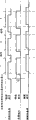
For fear of this situation, for example as shown in Figure 6, preferably, only when carrying recording materials, apply the photographic fixing bias voltage basically by the clamping of photographic fixing bite.That is, in the drawings, the situation when carrying recording materials by the clamping of photographic fixing bite represents that with thick line constantly corresponding with this, the induction moment, the bias voltage of expressing top sensor 8, grate paper-arranaging sensor 27 among the figure apply constantly." connection " of sensor class is illustrated in each sensor place recording materials and is positioned at detecting means.
As shown in the figure, the moment that applies bias voltage to the electric conductivity undercoat 13b of photographic fixing film 13 is to set like this, promptly utilizing after top sensor 8 detects the front end of recording materials P, postpone with the position that becomes the connection degree from top sensor to the distance of photographic fixing bite N time T 1 identical or less time divided by the transporting velocity gained, begin to apply bias voltage by bias voltage applying mechanism 16.
And, setting about the cut-out of photographic fixing bias voltage, be after top sensor 8 detects recording materials P, to the time T 2 of distance of photographic fixing bite N, cut off the bias voltage that applies by the bias voltage applying mechanism divided by the transporting velocity gained in the position that becomes the disconnection degree through the top sensor of associating.
About the value of photographic fixing bias voltage, clamping applies the bias voltage identical with toner polarity with value Vf during carrying recording materials on the electric conductivity undercoat 13b of photographic fixing film 13 in photographic fixing bite N.Carry number that this Vf value is descended gradually by the recording materials when printing continuously, be reduced in the toner picture photographic fixing just electric charge injection afterwards on the recording materials, and prevent the photographic fixing conditions of streaking.
The face of printing as defined above is described continuously, when breaking away from the photographic fixing bite in last recording materials rear end and passing through grate paper-arranaging sensor 27, the trailer record material is fed in the absence in the imaging device by organization of supply, being judged as continuous printing finishes, afterwards, receive print signal once more at imaging device, begin to supply under the situation of recording materials, above-mentioned bias voltage is set and is turned back to A-stage.
(4) affirmation of effect
In order to confirm the effect in the present embodiment, the present inventor has implemented following experiment.
1) employed imaging device (Fig. 1) is the laser beam printer of 250mm/sec for the recording materials transporting velocity, be in developing apparatus, to make toner electronegative, and utilize the jump development method on photosensitive drums, to form the toner picture, utilize transfer roll on recording materials, to form the device of image.
2) as fixing device (Fig. 2, Fig. 3), above-mentioned photographic fixing film 13 forms the member of tubular as the 13a of basic unit with the SUS304 material of external diameter 30mm, thickness 40 μ m, apply the electric conductivity undercoat 13b of 4 μ m on its outer surface, and then, the PFA that is dispersed with conductive member that forms 10 μ m is as release property layer 13c, and the ratio resistance of this release property layer 13c is 1 * 10
9Ω cm.
And backer roll 20 form the elastic layer 22 that is made of conductivity silicon rubber of thickness 4mm, external diameter 30mm on the outside surface of the aluminium core 21 of external diameter 22mm, and then the outer 23 insulation PFA pipes with thickness 40 μ m forms.
3) Shi Yan enforcement is, utilize bias voltage applying mechanism 16 on the electric conductivity undercoat 13b of above-mentioned metallic photographic fixing film 13, to apply the bias voltage identical with toner polarity, when printing continuously, this bias voltage is changed according to the heat fixer number of recording materials, degree to the photographic fixing hangover compares, and observes, contrasts adhering to, accumulate the lip-deep toning dosage of photographic fixing film surface and backer roll.
The contrast of photographic fixing hangover is, the degree (the the the 1st, the 21st, the 51st, the 81st) that the junior one during to the bias voltage that changes corresponding to number at each is opened compares; The contrast of accumulation is, leaves one minute stop time as one-stop operation between each operation with continuous 500 in the paper feeding cassette of 500 of supplies, on the film under the situation of continuous 20 subjobs and the toner contamination on the backer roll accumulate and compare.
After the photographic fixing bias voltage was once stopping, the number counter became original state, and the bias value that is produced by bias voltage applying mechanism 16 turns back to original state.Thereby, per 500 operation is applied same bias value.
4) below, the bias value under each number during continuous printing the in table 1 in each experiment of expression experiment 1~3.
Table 1
| |
1~20 | 21~50 | 51~80 | 81~500 |
| Experiment 1 | -1000V | -1000V | -1000V | -1000V |
| Experiment 2 | -1000V | -800V | -600V | -500V |
| Experiment 3 | -1000V | -700V | -400V | -200V |
Photographic fixing hangover when 5) table 2 expression applies each bias voltage, the comparing result of toner contamination.In table 2, the numeric representation grade, 5 expressions are no problem degree fully, 4 expression hangovers or toner contamination have the degree of small problem, the degree that 3 expressions can allow, the defective degree of 2 expression generation problems, the very poor degree of 1 expression (in the table 5 of back, table 7, table 10, adopting the same manner to represent).The evaluation of photographic fixing hangover is the evaluation to the substantial middle position of recording materials.
Table 2

By above result as can be known, under situation about printing continuously, in the constant experiment 1 of photographic fixing bias voltage maintenances-1000V, the degree of photographic fixing hangover is good, but toner contamination has problems, and from the 10th subjob, has also observed toner contamination on recording materials.
And in the big experiment 3 of the slippage of bias voltage, toner contamination does not take place fully, but because photographic fixing bias voltage slippage is excessive, the photographic fixing hangover that the degree that produces halfway is very poor.By this result as can be known, when printing continuously, descend gradually, can not produce toner contamination, and can satisfy the requirement of photographic fixing hangover aspect by in suitable scope, making the photographic fixing bias value.
6) and, in the present embodiment, though the method that only applies the bias voltage identical with toner polarity on the electric conductivity undercoat 13b of photographic fixing film 13 is illustrated, but, as described below, also can adopt utilize other bias voltage applying mechanism the backer roll conductive layer be positioned at photographic fixing bite downstream and electroconductive member that recording materials contact on apply bias voltage application system with the opposite polarity bias voltage of toner.
Promptly, in Fig. 7, backer roll 20 forms the elastic layer 22 of conductivity silicon rubber of being dispersed with electroconductive members such as carbon black etc. on the outside of metal core 21, form insulativity thermotolerance pipe such as PFA in its outside as release property layer 23, with the second bias voltage applying mechanism 28 be connected to this backer roll metal-cored 21 on.
And, preferably between this second bias voltage applying mechanism 28 and backer roll metal-cored 21, clamp rectifier cells 24 such as diode.
And, the above-mentioned second bias voltage applying mechanism 28, also can adopt provide to backer roll metal-cored 21 with the opposite polarity bias voltage of toner (photographic fixing bias voltage B) in, to the metal-cored structure that applies bias voltage of the electric conductivity row paper rubber rollers 25 that is configured in photographic fixing bite downstream.But, the voltage that these apply, being specially can be different to the metal-cored bias voltage that applies of backer roll and the magnitude of voltage of the bias voltage that electric conductivity row paper rubber rollers is applied, and prepares bias voltage applying mechanism 28 respectively individually, also no problem fully.
Utilize said structure, on the electric conductivity undercoat 13b of photographic fixing film 13, apply the bias voltage identical (photographic fixing bias voltage A) by the first bias voltage applying mechanism 16 with toner polarity, simultaneously, utilize the second bias voltage applying mechanism 28 on backer roll 20 and row's paper rubber rollers 25 metal-cored, to apply and the opposite polarity bias voltage of toner (photographic fixing bias voltage B).
The time diagram that the expression bias voltage applies among Fig. 8.In the drawings, as previously described, the bias voltage of photographic fixing bias voltage A for applying to the electric conductivity undercoat 13b of photographic fixing film 13 from the first bias voltage applying mechanism 16 applies the bias value Vf identical with toner polarity to recording materials when being carried out the clamping conveying by the photographic fixing bite.And photographic fixing bias voltage B represents from the second bias voltage applying mechanism 28 to metal-cored 21 bias voltages that apply of backer roll 20 and the bias voltage that applies to the electric conductivity row paper rubber rollers 25 that is positioned at photographic fixing bite downstream.Thereby, apply bias value Vp on, the electric conductivity row paper rubber rollers 25 metal-cored 21 at backer roll.
At this, the moment that bias voltage applies is, as shown in Figure 8, utilizing after top sensor 8 detects the front end of recording materials, through the stipulated time, side by side applies photographic fixing bias voltage A and B basically.These bias values are respectively Vf, Vp, and Vf is the bias value identical with toner polarity, and Vp is and the opposite polarity bias value of toner.And in the moment of discharging recording materials from the photographic fixing bite, saying so in more detail detects the recording materials rear end afterwards through the moment of stipulated time in top sensor 8, make these bias voltages be reduced to the cut-out degree respectively.
And, at least one of above-mentioned bias value Vf or Vp is variable bias, when printing continuously, potential difference (PD) between metal-cored 21 or the electric conductivity row paper rubber rollers 25 of the electric conductivity undercoat 13b of photographic fixing film 13 and backer roll 20 is descended gradually, thereby can be improved photographic fixing hangover and prevent the effect of toner contamination as previously described.
And, under the electroconductive member to above-mentioned backer roll 20 and photographic fixing bite downstream applies situation with the opposite polarity bias voltage of toner, even the electric conductivity undercoat 13b of photographic fixing film 13 forms state electrical ground, and is self-evident, also can obtain identical effect.
<the second embodiment 〉
Below, second embodiment described.The one-piece construction of imaging device is identical with the Fig. 1 shown in aforementioned first embodiment, and the structure in the heat fixing device is also identical with Fig. 2, Fig. 3 and the Fig. 7 shown in aforementioned first embodiment, so omit the explanation to them.
Present embodiment is characterised in that, be clamped in the photographic fixing bite and no show still is positioned under the state of electroconductive member 25 in photographic fixing bite downstream at the front end of recording materials, the electric conductivity undercoat 13b of photographic fixing film 13 and the potential difference (PD) between the backer roll conductive elastic layer are set greatlyyer, whereby, prevent the photographic fixing hangover of recording materials front end.
Utilize the heat fixing device structure of Fig. 7 and the time diagram of Fig. 9 that present embodiment is described.In Fig. 7, utilize bias voltage applying mechanism 16 on the electric conductivity undercoat 13b of photographic fixing film 13, to apply the photographic fixing bias voltage A identical with toner polarity, on the other hand, utilize bias mechanism 28, backer roll 20 metal-cored 21 and be configured on the electric conductivity row paper rubber rollers 25 in photographic fixing bite downstream and apply and the opposite polarity bias voltage B of toner.At this moment, as shown in Figure 9, after between process is stipulated after top sensor 8 detects the recording materials front end, at a moment before the recording materials front end will enter into photographic fixing bite N, apply photographic fixing bias voltage A with bias value Vf, on the other hand, approximately, apply photographic fixing bias voltage B with bias value Vb, and detect the moment of recording materials front end at the grate paper-arranaging sensor 27 of Fig. 7 with the photographic fixing bias voltage A while, it is switched to the bias value Vp littler than Vb, apply bias voltage.
And, when printing continuously, according to the photographic fixing number make above-mentioned under recording materials P and photographic fixing bite N and exit roller 25 state of contact above-mentioned bias value Vf or at least one bias value among the Vp descend gradually, whereby, reduce the potential difference (PD) between the electroconductive member in the electric conductivity undercoat 13b of photographic fixing film 13 and photographic fixing bite downstream gradually or interimly, control the magnitude of current that flows through circuit via recording materials.
According to top described, first embodiment is such as described above, can not produce the toner contamination to photographic fixing film 13 and backer roll 20 when printing continuously, can form preferable image.
And, feature as present embodiment, for the recording materials front end with before the electroconductive member 25 that is configured in photographic fixing bite downstream contacts till the image of recording materials front end by the photographic fixing bite, can guarantee potential difference (PD) corresponding to bias value Vf and Vb, whereby, by increasing the binding force on recording materials, can also improve the photographic fixing hangover of recording materials front end to unfixed toner image.
And, rectifier cells such as diode 24 are connected on the backer roll metal-cored 21, even photographic fixing bias voltage B switches to Vp from Vb, backer roll metal-cored 21 and conductive elastic layer 22 can not drop to very low current potential immediately, thereby, can not cause that image is bad owing to bias voltage switches to Vp from Vb.
For the effect of the photographic fixing hangover of confirming to improve the recording materials front end, confirm at this moment the photographic fixing film and the toner contamination situation on the backer roll, conversion photographic fixing bias voltage Vf, Vb, Vp are to confirm respectively.The structure of the heat fixing device that is used to confirm and the confirmation method of toner contamination, identical with structure and the method shown in aforementioned first embodiment, therefore, omit explanation to it.
In addition, about toner contamination, owing to can carry out to a certain degree prediction from the result of aforementioned first embodiment, in the present embodiment, the Vf potential difference (PD) of aforementioned first embodiment is divided into film side and backer roll side, and the bias value of each Vf and Vp is general, and its setting is shown in Table 3.
And the definition of printing is identical with aforementioned first embodiment continuously, and in the moment that this continuous printing was once being interrupted, the bias voltage of table 3 is set the setting when turning back to the 1st.
Table 3
| |
1~20 | 21~50 | 51~80 | 81~500 |
| Vf | -500V | -400V | -300V | -250V |
| Vp | -500V | -400V | -300V | -250V |
The setting bias voltage Vb of each experiment in the expression experiment 4~7 in table 4.
Table 4
| |
1~20 | 21~50 | 51~80 | 81~500 |
| Experiment 4 | -500V | -400V | -300V | -250V |
| Experiment 5 | -500V | -500V | -500V | -500V |
| Experiment 6 | -800V | -750V | -700V | -650V |
| Experiment 7 | -1000V | -1000V | -1000V | -1000V |
The result of the photographic fixing hangover of the recording materials front end when bias voltage is switched in expression in table 5, and on the photographic fixing film under the printing situation continuously and the comparing result of the toner contamination on the backer roll.
Table 5

From above result as can be known, at the recording materials front end still under the state that does not have circuit before the no show busbar paper rubber rollers 25, the photographic fixing hangover of recording materials front end is serious, in the experiment 4 of carrying out the bias voltage setting identical with first embodiment, a grade descends near the central authorities of photographic fixing hangover than recording materials of front end.
On the other hand, only improve the bias value of front end, make the electric conductivity undercoat 13b of photographic fixing film 13 and the potential difference (PD) between the backer roll conductive elastic layer keep bigger, it is favourable trailing for the photographic fixing at recording materials front end place.
But on the other hand, though only be at front end, under the state of the excessive potential difference (PD) of maintenance, the pollution of toner also can worsen.This is because using under the situation of paper as recording materials, is easy to make the paper powder to be attached on the photographic fixing film or on the backer roll at the very strong bias voltage of the wood chip portion of paper.Usually in cutting paper, because of the influence of the cut-out of the wood chip portion of paper is easy to produce the paper powder, therefore, if on photographic fixing film or backer roll the more paper powder of savings, then the release property on photographic fixing film or backer roll surface descends, and is easy to cause toner contamination.
Thereby, the recording materials front end carried by the clamping of photographic fixing bite and as yet not with state before the electroconductive member in photographic fixing bite downstream contacts under, keep suitable potential difference (PD) between electric conductivity undercoat by making the photographic fixing film and the backer roll conductive elastic layer, can not produce toner contamination on the photographic fixing film or on the backer roll surface, and can improve the photographic fixing hangover of recording materials front end.Particularly, the situation when contacting with the electroconductive member in photographic fixing bite downstream with recording materials is compared, and it is bigger that above-mentioned potential difference (PD) keeps, and therefore, the situation that the photographic fixing of recording materials front end hangover worsens disappears.
And, though in the present embodiment, respectively the electric conductivity undercoat of photographic fixing film and backer roll is metal-cored and conductive elastic layer, electric conductivity row paper rubber rollers apply bias voltage respectively system are illustrated, but so long as can set the method for same potential difference (PD), any bias voltage applies form can.Promptly, as long as what adopt is with recording materials front end and potential difference (PD) between electroconductive member after being right after the photographic fixing bite contacts in photographic fixing film conductivity undercoat before and the backer roll conductive elastic layer, the photographic fixing film conductivity undercoat when setting to such an extent that contact with electroconductive member than recording materials and the big method of potential difference (PD) of this electroconductive member, its form is not subjected to any restriction.
<the three embodiment)
Below, the 3rd embodiment described.The one-piece construction of imaging device is with identical at the Fig. 1 shown in aforementioned first embodiment, and the structure in the heat fixing device is also identical with Fig. 2, Fig. 3 and the Fig. 7 shown in aforementioned first embodiment, thereby omits the explanation to it.
Present embodiment is characterised in that, changes the setting value of photographic fixing bias voltage according to the environment for use of imaging device.
Usually, for the photographic fixing hangover shown in aforementioned first embodiment and second embodiment, high more as the paper water percentage of recording materials, then the tendency of E Huaing is serious more.This point is not hard to imagine by following mechanism, promptly is contained in moisture in the paper and is heated in the photographic fixing bite and becomes water vapour, and the unfixed toner image on the recording materials is blown afloat.
On the other hand, very big with the static factor relation about the toner contamination to fixing member and pressing element, particularly under the environment of low humidity, toner is easy to be subjected to electric field effects, causes toner contamination easily.
As known from the above, present embodiment is for the imaging device of the mechanism with environment such as detected temperatures/humidity, setting value according to environment change photographic fixing bias voltage, simultaneously, according to the number in the continuous printing photographic fixing bias voltage is descended gradually, thereby a kind of bad high-quality imaging device of image that causes because of photographic fixing hangover and toner contamination that can not produce is provided.
Adopt the heat fixing device of the Fig. 2 shown in aforementioned first embodiment and the bias voltage time diagram of Fig. 6 that present embodiment is described.
Imaging device in the present embodiment has at least one testing agency in temperature testing organization or the Humidity Detection mechanism as environment measuring mechanism, detects the environment for use of imaging device.In Fig. 2,101 is this environment measuring mechanism, and the testing environment information of this environment measuring mechanism 101 is input in the control circuit portion 100.Control circuit portion 100 can be divided into the environmental information that environment measuring mechanism 101 is detected for example 15 ℃ of temperature, humidity low-humidity environment (hereinafter referred to as the L/L environment) and 30 ℃ of the temperature, the high humidity environment (hereinafter referred to as H/H environment) of humidity more than 80% below 10%.And,, be judged as normal wet environment (hereinafter referred to as the N/N environment) under the situation of the state between them.Thereby, in the L/L environment, owing to be difficult for producing the photographic fixing hangover, so adopt the favourable bias voltage of toner contamination is set, in the H/H environment, the favourable bias voltage of photographic fixing hangover is set on the other hand, can be prevented photographic fixing hangover and toner contamination simultaneously by adopting.And, in the N/N environment, adopt the setting between L/L environment and H/H environment.
For example, use heat fixing device shown in Figure 2, as realizing the bias voltage that applies recited above, the photographic fixing bias value Vf of the electric conductivity undercoat 13b of the photographic fixing film in the bias voltage time diagram of Fig. 6 is adopted setting in the table 6.
Table 6
| |
1~20 | 21~50 | 51~80 | 81~ |
| The L/L environment | -600V | -500V | -400V | -300V |
| The N/N environment | -1000V | -800V | -600V | -500V |
| The H/H environment | -1400V | -1200V | -1000V | -800V |
The result who sets, the photographic fixing hangover under each environment and toner contamination are estimated with respect to the bias voltage in above each environment is illustrated in the table 7.In addition, the imaging device that uses in evaluation and the structure of heat fixing device, evaluation method are identical with aforementioned first embodiment, thereby omit the explanation to it.
Table 7

On the one hand, in the L/L environment, under the situation that the setting bias voltage when adopting the N/N environment is printed, toner contamination worsens, and becomes 2 grades, on the other hand, under the H/H environment, under the situation that the setting bias voltage during with the N/N environment prints, photographic fixing hangover grade drops to 2 grades.
And, under the L/L environment, the photographic fixing bias voltage is being fixed on-600V and situation about printing continuously under, deterioration has taken place in toner contamination equally.
Therefore, change the bias value of heat fixing device under each environment, the number during according to continuous the printing makes the method that bias value descends gradually of setting, as improve the photographic fixing hangover in each environment, the method for toner contamination is effective.
<the four embodiment 〉
Below, the 4th embodiment described.The structure of imaging device main body is identical with the Fig. 1 shown in aforementioned first embodiment, and the structure in the heat fixing device is also identical with Fig. 2, Fig. 3 and the Fig. 7 shown in aforementioned first embodiment, thereby omits the explanation to it.
Present embodiment is characterised in that, in the imaging device with a plurality of recording materials transporting velocities, changes the setting value of photographic fixing bias voltage according to the recording materials transporting velocity of imaging device.
Usually, the hangover of the photographic fixing shown in the previous embodiment is accelerated along with the transporting velocity of recording materials and is worsened.Its reason can easily be inferred as follows: when recording materials enter into heat fixing device, recording materials must enter into the photographic fixing bite against the water vapour that produces in recording materials throughput direction entrance side (the photographic fixing bite nearby), perhaps under the fast situation of transporting velocity, must make toner fusion quickly in very short heat time heating time, so the force of the water vapour that produces from recording materials strengthens.
On the other hand, under the slow-footed situation of recording materials, when at fixing member be configured in when being provided with potential difference (PD) between the electroconductive member in photographic fixing bite downstream, flow through the current value of the circuit that forms via recording materials, current value when specific rate is fast under the situation of same electrical potential difference is smaller, but, then reach the abundant magnitude of current if from ratio with respect to speed.
Thereby, if under the slow situation of transporting velocity, adopt the optimized photographic fixing bias voltage under the fast situation of the transporting velocity of recording materials, though then the photographic fixing hangover improves, owing to be easy to flow through excessive electric current, as a result, cause stained and deterioration toner contamination.
And, in imaging device, have can according to the kind of recording materials change transporting velocity device, can in the resolution of switching the toner picture, change the device etc. of the transporting velocity of recording materials.
In these cases, can carry out in the imaging device of imaging, be necessary to set the optimum bias value that is used to prevent the photographic fixing hangover according to each recording materials transporting velocity with multiple recording materials transporting velocity.And, as previously described, trail for photographic fixing, because the transporting velocity of recording materials is comparatively favourable slowly, so when the transporting velocity of recording materials is slow more, be used for realizing simultaneously preventing the photographic fixing hangover and preventing that the photographic fixing bias voltage slippage of toner contamination is more little shown in aforementioned first and second embodiment.
As known from the above, for example, use heat fixing device shown in Figure 2, as realizing the bias voltage that applies recited above, make the photographic fixing bias value Vf in the bias voltage time diagram of Fig. 6, set according to table 8 corresponding to each recording materials transporting velocity for the electric conductivity undercoat 13b of photographic fixing film 13.In addition, the imaging device that can between the 125mm/sec of 250mm/sec and its Half Speed, select of service recorder materials conveyance speed.
Table 8
| |
1~20 | 21~50 | 51~80 | 81~ |
| During 250mm/sec | -1000V | -800V | -600V | -500V |
| During 125mm/sec | -600V | -550V | -500V | -450V |
Utilize above-mentioned bias voltage to set and heat fixing device shown in Figure 2, photographic fixing hangover and toner contamination are estimated, set adjusting and evaluation result and be illustrated in table 9 and the table 10.
In 10 tables, the bias voltage of experiment 8 expressions during with the recording materials transporting velocity of 250mm/sec, according to the 250mm/sec in the top table 8 set recording materials carried out result under the situation of heat fixer, and the bias voltage of experiment 9 expressions during with the recording materials transporting velocity of 125mm/sec, according to the 125mm/sec in the table 8 set recording materials are carried out result under the situation of heat fixer.In addition, as a comparison, experiment 10 and experiment 11 be illustrated under the recording materials transporting velocity of 125mm/sec, set result under the situation of carrying out heat fixer according to the bias voltage of following table 9.
Table 9
| |
1~20 | 21~50 | 51~80 | 81~ |
| Experiment 10 | -1000V | -800V | -600V | -500V |
| Experiment 11 | -600V | -480V | -360V | -300V |
Table 10

And, be fixed as at recording materials transporting velocity, photographic fixing bias value-600V and under the situation about printing continuously, the photographic fixing hangover is good, but the degree that taken place is 2 grades a toner contamination with 125mm/sec.
By the result of last table as can be known, under the slow situation of the transporting velocity of recording materials, when the photographic fixing bias voltage of setting hanged down, the photographic fixing hangover can not produce deterioration, and can prevent toner contamination.But the photographic fixing bias voltage descends and causes when excessive the photographic fixing hangover to worsen.
And under the slow situation of recording materials transporting velocity, the little bias voltage of bias voltage slippage during from continuous printing of the setting bias voltage at continuous printing initial stage is set, and the optimal bias that becomes for photographic fixing hangover, toner contamination is set.
Thereby, in the imaging device that can set multiple recording materials transporting velocity, by taking following measure, can prevent photographic fixing hangover and toner contamination under the various speed: have corresponding to the transporting velocity of recording materials set bias voltage and according to the transporting velocity of each recording materials and the number when printing continuously make and set the bias voltage applying mechanism that bias value descends gradually, the photographic fixing bias voltage slippage under the situation that the recording materials transporting velocity is slow is set than little under the fast situation of recording materials transporting velocity.
<other 〉
1) though each embodiment serves as main being illustrated with the heat fixing device of being furnished with photographic fixing film 13, but for the heat fixing device that adopts warm-up mill, so long as at fixing member with in the system that forms circuit between photographic fixing bite downstream and the electroconductive member that recording materials contact, needless to say, has identical effect.
2) heating arrangement of fixing member also can adopt the electromagnetic induction heating mode.
3) heat fixing device of film type of heating, though adopt pressurization rotary body type of drive in an embodiment, but, also can adopt on the inner peripheral surface of annular photographic fixing film driven roller is set, on one side film is applied the device of the mode that tension force drives on one side, can also adopt film is formed the end drum is arranged, driving the device of the mode of its motion of reel.
4) in heat fixing device of the present invention, not only comprise uncertain image is carried out heat fixer and form the fixing device of permanent image on recording materials, also comprise the image heater of the interim photographic fixing of uncertain image on recording materials, heat again so that improve the image heater etc. of imaging surface character such as gloss carrying the record images material.
5) imaging mode of imaging device is not limited to the electrofax mode, also can adopt electrostatic recording mode, return to zero etc., perhaps also can adopt transfer printing mode or direct mode.
As mentioned above, adopt the present invention, when continuously recording materials being carried out heat fixer, for the continuous printing initial stage that is easy to produce the photographic fixing hangover, by via recording materials at fixing member be configured between the conductive member in photographic fixing bite downstream and form circuit, by the conductive part of fixing member and the electric field that pressure drop produced between the recording materials, improve binding force to the unfixed toner image on the recording materials, can prevent the generation of photographic fixing hangover.
And, in the latter half of printing continuously, by the photographic fixing bias voltage is descended, the magnitude of current of foregoing circuit is flow through in control, thereby preventing owing to flow through excessive electric current that iunjected charge causes toner to become opposite polarity in just by the toner of photographic fixing bite takes place stained and fixing member and pressing element are caused toner contamination.
Claims (18)
1. heat fixing device, be furnished with:
Fixing member;
With aforementioned fixing member crimping and be formed for clamping/conveying and be formed with the photographic fixing bite of recording materials of uncertain image so that will be formed at the pressing element that uncertain image photographic fixing on the above-mentioned recording materials becomes permanent image;
The conductive member that contacts with recording materials in the downstream of the recording materials throughput direction of above-mentioned photographic fixing bite;
In above-mentioned fixing member and this conductive member at least one applied the bias voltage applying mechanism of variable bias;
Supplying with under the situation of the recording materials that are formed with uncertain image continuously, thus when recording materials by the time change the bias voltage control gear that the bias voltage that is applied by this bias voltage applying mechanism diminishes the power that keeps uncertain image on recording materials gradually or interimly.
2. heat fixing device as claimed in claim 1, it is characterized in that, this bias voltage control gear, under the situation of the state that continue to keep organization of supply when the moment of last recording materials rear end by the position of this photographic fixing bite, imaging device to begin supplying the trailer record material, be judged as the situation that recording materials are supplied with continuously, and be reduced in gradually or interimly recording materials by the time bias voltage that should apply.
3. heat fixing device as claimed in claim 2, it is characterized in that, between the recording materials between last recording materials and the trailer record material, during fixing member and pressing element directly do not contact via recording materials, this bias voltage control gear cuts off bias voltage.
4. heat fixing device as claimed in claim 2, it is characterized in that, aforementioned bias voltage applying mechanism, has the mechanism that the conductive part of fixing member is applied the bias voltage identical with toner polarity, and apply at least one mechanism in the mechanism with the opposite polarity bias voltage of toner to the conductive part of pressing element, and the bias voltage of at least one mechanism is variable, and before the recording materials front end contacts with the conductive member of the recording materials conveyance direction downstream side of photographic fixing bite, the potential difference (PD) of fixing member conductive part and pressing element conductive part, when contacting with above-mentioned conductive part than recording materials, the potential difference (PD) of fixing member conductive part and this conductive member is big.
5. heat fixing device as claimed in claim 1 is characterized in that aforementioned pressing element has conductive part, is connected with on this conductive part it is remained and the opposite polarity rectifier cell of toner.
6. heat fixing device as claimed in claim 1, it is characterized in that, adopt the imaging device of this heat fixing device to have the temperature of detection environment for use or at least one environment measuring mechanism in the humidity, and aforementioned bias voltage control gear, according to the testing result of this environment measuring mechanism, the bias voltage that control utilizes the bias voltage applying mechanism to be applied.
7. heat fixing device as claimed in claim 1, it is characterized in that, adopt the imaging device of this heat fixing device can set a plurality of recording materials transporting velocities, aforementioned bias voltage control gear is controlled the bias voltage that utilizes the bias voltage applying mechanism to apply according to the transporting velocity of setting.
8. heat fixing device as claimed in claim 2, it is characterized in that, adopt the imaging device of this heat fixing device can set a plurality of recording materials transporting velocities, the bias voltage applying mechanism so that the transporting velocity of setting compare when fast when slow, so that the less mode of potential difference (PD) between the conductive member in the conductive part of fixing member and photographic fixing bite downstream utilizes the bias voltage applying mechanism to apply bias voltage, and, remain on the moment of the rear end of last recording materials continuing by the photographic fixing bite, the organization of supply of imaging device has begun to supply under the situation of state of trailer record material, compare when fast when the transporting velocity of setting is slow, the slippage of the bias voltage that is changed by the heating number of recording materials is less.
9. heat fixing device as claimed in claim 1 is characterized in that, aforementioned bias voltage control gear under the situation without interruption, for the recording medium of after this being supplied, applies constant bias voltage above the regulation number at recording materials.
10. heat fixing device as claimed in claim 1 is characterized in that, adopts any one mode in hot-rolling mode and the film type of heating.
11. an imaging device is characterized in that it is furnished with:
On recording materials, form the imaging portion of uncertain image;
Fixing member;
With aforementioned fixing member crimping and be formed for the above-mentioned photographic fixing bite that is formed with the recording materials of uncertain image of clamping/conveying, the uncertain image photographic fixing that is formed by above-mentioned imaging portion should be become the pressing element of permanent image on above-mentioned recording materials;
The conductive member that contacts with recording materials in the downstream of the recording materials throughput direction of above-mentioned photographic fixing bite;
In above-mentioned fixing member and this conductive member at least one applied the bias voltage applying mechanism of variable bias;
Supplying with under the situation of the recording materials that are formed with uncertain image continuously, thus when recording materials by the time change the bias voltage control gear that the bias voltage that is applied by this bias voltage applying mechanism diminishes the power that keeps uncertain image on recording materials gradually or interimly.
12. imaging device as claimed in claim 11, it is characterized in that, this bias voltage control gear, under the situation of the state that continue to keep organization of supply when the moment of last recording materials rear end by the position of this photographic fixing bite, imaging device to begin supplying the trailer record material, be judged as the situation that recording materials are supplied with continuously, and be reduced in gradually or interimly recording materials by the time bias voltage that should apply.
13. imaging device as claimed in claim 12, it is characterized in that, between the recording materials between last recording materials and the trailer record material, during fixing member and pressing element directly do not contact via recording materials, this bias voltage control gear cuts off bias voltage.
14. imaging device as claimed in claim 12, it is characterized in that, aforementioned bias voltage applying mechanism, has the mechanism that the conductive part of fixing member is applied the bias voltage identical with toner polarity, and apply at least one mechanism in the mechanism with the opposite polarity bias voltage of toner to the conductive part of pressing element, and the bias voltage of at least one mechanism is variable, and before the recording materials front end contacts with the conductive member of the recording materials conveyance direction downstream side of photographic fixing bite, the potential difference (PD) of fixing member conductive part and pressing element conductive part, when contacting with above-mentioned conductive part than recording materials, the potential difference (PD) of fixing member conductive part and this conductive member is big.
15. imaging device as claimed in claim 11 is characterized in that, aforementioned pressing element has conductive part, is connected with on this conductive part it is remained and the opposite polarity rectifier cell of toner.
16. imaging device as claimed in claim 11, it is characterized in that, above-mentioned imaging portion has the temperature that detects environment for use or at least one environment measuring mechanism in the humidity, and aforementioned bias voltage control gear, according to the testing result of this environment measuring mechanism, the bias voltage that control utilizes the bias voltage applying mechanism to be applied.
17. imaging device as claimed in claim 11 is characterized in that, above-mentioned imaging portion can set a plurality of recording materials transporting velocities, and aforementioned bias voltage control gear is controlled the bias voltage that utilizes the bias voltage applying mechanism to apply according to the transporting velocity of setting.
18. imaging device as claimed in claim 12, it is characterized in that, above-mentioned imaging portion can set a plurality of recording materials transporting velocities, the bias voltage applying mechanism so that the transporting velocity of setting compare when fast when slow, the less mode of potential difference (PD) between the conductive member in the conductive part of fixing member and photographic fixing bite downstream utilizes the bias voltage applying mechanism to apply bias voltage, and, remain on the moment of the rear end of last recording materials continuing by the photographic fixing bite, the organization of supply of imaging device has begun to supply under the situation of state of trailer record material, compare when fast when the transporting velocity of setting is slow, the slippage of the bias voltage that is changed by the heating number of recording materials is less.
Applications Claiming Priority (2)
| Application Number | Priority Date | Filing Date | Title |
|---|---|---|---|
| JP248307/2002 | 2002-08-28 | ||
| JP2002248307A JP3990957B2 (en) | 2002-08-28 | 2002-08-28 | Heat fixing device |
Publications (2)
| Publication Number | Publication Date |
|---|---|
| CN1495574A CN1495574A (en) | 2004-05-12 |
| CN100511019C true CN100511019C (en) | 2009-07-08 |
Family
ID=31972510
Family Applications (1)
| Application Number | Title | Priority Date | Filing Date |
|---|---|---|---|
| CNB031559468A Expired - Fee Related CN100511019C (en) | 2002-08-28 | 2003-08-27 | Heating photographic fixing device |
Country Status (3)
| Country | Link |
|---|---|
| US (1) | US6915099B2 (en) |
| JP (1) | JP3990957B2 (en) |
| CN (1) | CN100511019C (en) |
Families Citing this family (21)
| Publication number | Priority date | Publication date | Assignee | Title |
|---|---|---|---|---|
| JP2005166299A (en) * | 2003-11-28 | 2005-06-23 | Canon Inc | Heating device and image forming device |
| JP4630673B2 (en) * | 2004-02-03 | 2011-02-09 | キヤノン株式会社 | Fixing device |
| KR20050080575A (en) * | 2004-02-10 | 2005-08-17 | 삼성전자주식회사 | Fusing roller apparatus of electro-photographic image forming apparatus |
| EP1569046A1 (en) * | 2004-02-27 | 2005-08-31 | Canon Kabushiki Kaisha | Image-forming apparatus with a detector unit for detecting the temperature of a recording medium |
| US7215899B2 (en) * | 2004-02-27 | 2007-05-08 | Canon Kabushiki Kaisha | Image forming apparatus having temperature sensing element for sensing temperature of recording material |
| JP4262119B2 (en) | 2004-02-27 | 2009-05-13 | キヤノン株式会社 | Image forming apparatus |
| JP2005316443A (en) | 2004-03-30 | 2005-11-10 | Canon Inc | Image-heating device and conveyance roller used for the device |
| JP2006084821A (en) * | 2004-09-16 | 2006-03-30 | Canon Inc | Heat fixing apparatus |
| JP4773785B2 (en) | 2004-09-28 | 2011-09-14 | キヤノン株式会社 | Image heating device |
| JP2009020158A (en) * | 2007-07-10 | 2009-01-29 | Ricoh Co Ltd | Fixing device and image forming apparatus |
| JP5366427B2 (en) * | 2008-04-09 | 2013-12-11 | キヤノン株式会社 | Film and image heating apparatus provided with the film |
| US8014714B2 (en) * | 2008-08-28 | 2011-09-06 | Xerox Corporation | Fusers, printing apparatuses and methods of fusing toner on media |
| US20110311253A1 (en) * | 2010-06-21 | 2011-12-22 | Toshiba Tec Kabushiki Kaisha | Image forming apparatus and image formation processing method |
| JP5910111B2 (en) * | 2012-01-26 | 2016-04-27 | 富士ゼロックス株式会社 | Fixing apparatus and image forming apparatus |
| US9323185B2 (en) * | 2014-03-25 | 2016-04-26 | Canon Finetech Inc. | Image forming apparatus having heating unit heating recording material, pressurizing unit forming a nip between itself and heating unit, and control unit |
| JP6594043B2 (en) * | 2014-08-04 | 2019-10-23 | キヤノン株式会社 | Fixing device |
| JP6456165B2 (en) | 2015-01-29 | 2019-01-23 | キヤノン株式会社 | Image forming apparatus |
| JP6598650B2 (en) * | 2015-11-17 | 2019-10-30 | キヤノン株式会社 | Fixing apparatus and image forming apparatus |
| JP6776967B2 (en) * | 2017-03-23 | 2020-10-28 | 京セラドキュメントソリューションズ株式会社 | Fixing device and image forming device |
| US10429780B1 (en) | 2018-11-26 | 2019-10-01 | Toshiba Tec Kabushiki Kaisha | Image forming apparatus and method of controlling image forming apparatus |
| JP7391614B2 (en) * | 2019-11-01 | 2023-12-05 | 東芝テック株式会社 | Fixing device and image forming device |
Family Cites Families (49)
| Publication number | Priority date | Publication date | Assignee | Title |
|---|---|---|---|---|
| US38125A (en) * | 1863-04-07 | Improvement in mariners compasses | ||
| US168202A (en) * | 1875-09-28 | Improvement in water-wheels | ||
| US29853A (en) * | 1860-09-04 | Improvement in seed-planters | ||
| US118363A (en) * | 1871-08-22 | Improvement in propulsion of vessels | ||
| US118977A (en) * | 1871-09-12 | Improvement in single-wheel toy-propellers | ||
| US5300997A (en) * | 1987-06-16 | 1994-04-05 | Canon Kabushiki Kaisha | Image fixing apparatus |
| DE3854801T2 (en) * | 1987-06-16 | 1996-06-13 | Canon Kk | Image fixing device |
| JP2516886B2 (en) | 1987-06-16 | 1996-07-24 | キヤノン株式会社 | Image heating device |
| JP2646444B2 (en) | 1988-12-12 | 1997-08-27 | キヤノン株式会社 | Image heating fixing device |
| US5083168A (en) * | 1988-11-15 | 1992-01-21 | Canon Kabushiki Kaisha | Fixing device and fixing heater for use in the same |
| US5262834A (en) * | 1988-12-06 | 1993-11-16 | Canon Kabushiki Kaisha | Image fixing apparatus |
| US5162634A (en) * | 1988-11-15 | 1992-11-10 | Canon Kabushiki Kaisha | Image fixing apparatus |
| US6005594A (en) * | 1990-03-26 | 1999-12-21 | Canon Kabushiki Kaisha | Fixing apparatus having a fixing roller with a non-adhesive surface layer |
| JP2884716B2 (en) | 1990-06-11 | 1999-04-19 | キヤノン株式会社 | Image heating device |
| US5148226A (en) * | 1990-06-11 | 1992-09-15 | Canon Kabushiki Kaisha | Heating apparatus using endless film |
| JP2884717B2 (en) | 1990-06-11 | 1999-04-19 | キヤノン株式会社 | Image heating device |
| JP2940077B2 (en) | 1990-06-11 | 1999-08-25 | キヤノン株式会社 | Heating equipment |
| JP2861280B2 (en) | 1990-06-11 | 1999-02-24 | キヤノン株式会社 | Heating equipment |
| JP2884715B2 (en) | 1990-06-11 | 1999-04-19 | キヤノン株式会社 | Image heating device |
| JP2884714B2 (en) | 1990-06-11 | 1999-04-19 | キヤノン株式会社 | Image heating device |
| JP2917424B2 (en) | 1990-06-11 | 1999-07-12 | キヤノン株式会社 | Image heating device |
| JP2884718B2 (en) | 1990-06-11 | 1999-04-19 | キヤノン株式会社 | Image heating device |
| EP0461595B1 (en) * | 1990-06-11 | 1996-03-13 | Canon Kabushiki Kaisha | Heating apparatus using endless film |
| JP2926904B2 (en) | 1990-06-11 | 1999-07-28 | キヤノン株式会社 | Image heating device |
| JPH04204982A (en) | 1990-11-30 | 1992-07-27 | Canon Inc | Heater |
| US5210579A (en) * | 1990-11-30 | 1993-05-11 | Canon Kabushiki Kaisha | Image fixing apparatus having a parting resin layer for reducing frictional resistance of the film through which the image is heated |
| JPH04204981A (en) | 1990-11-30 | 1992-07-27 | Canon Inc | Heater |
| JP2940161B2 (en) | 1990-11-30 | 1999-08-25 | キヤノン株式会社 | Image heating device |
| JPH04204983A (en) | 1990-11-30 | 1992-07-27 | Canon Inc | Heater |
| JP2900604B2 (en) | 1990-11-30 | 1999-06-02 | キヤノン株式会社 | Image heating device |
| JP3219518B2 (en) * | 1993-01-29 | 2001-10-15 | キヤノン株式会社 | Image forming device |
| US5682576A (en) * | 1994-06-07 | 1997-10-28 | Canon Kabushiki Kaisha | Fixing device |
| JP3441820B2 (en) * | 1994-11-01 | 2003-09-02 | キヤノン株式会社 | Heating equipment |
| JPH08314312A (en) * | 1995-05-22 | 1996-11-29 | Canon Inc | Rotary body for pressing, heating device and image forming device |
| JPH10142971A (en) * | 1996-11-06 | 1998-05-29 | Canon Inc | Image forming device |
| JP3372811B2 (en) * | 1997-02-03 | 2003-02-04 | キヤノン株式会社 | Heat fixing device |
| JPH1124492A (en) * | 1997-07-03 | 1999-01-29 | Canon Inc | Thermal fixing device |
| JPH11133803A (en) * | 1997-10-30 | 1999-05-21 | Canon Inc | Fixing device and image forming device |
| JP2000321895A (en) * | 1999-05-07 | 2000-11-24 | Canon Inc | Image heating device and image forming device |
| JP4250293B2 (en) * | 2000-02-10 | 2009-04-08 | キヤノン株式会社 | Fixing device |
| JP2001324892A (en) * | 2000-05-17 | 2001-11-22 | Canon Inc | Image heating device, and image forming device provided with the same |
| US6701102B2 (en) | 2000-12-01 | 2004-03-02 | Canon Kabushiki Kaisha | Method and apparatus for controlling the temperature in a fixing device of an image forming apparatus |
| JP3814542B2 (en) | 2001-02-20 | 2006-08-30 | キヤノン株式会社 | Image heating device |
| JP4125023B2 (en) | 2001-03-13 | 2008-07-23 | キヤノン株式会社 | Fixing device |
| JP2002268449A (en) * | 2001-03-13 | 2002-09-18 | Canon Inc | Fixing device and image forming apparatus |
| JP3970122B2 (en) | 2001-08-10 | 2007-09-05 | キヤノン株式会社 | Image heating apparatus having metal rotating body in contact with heater, rotating body, and method of manufacturing the rotating body |
| JP4261859B2 (en) | 2001-10-09 | 2009-04-30 | キヤノン株式会社 | Image heating device |
| JP4099098B2 (en) * | 2002-05-31 | 2008-06-11 | 株式会社リコー | Fixing device and image forming device |
| JP3977200B2 (en) * | 2002-08-23 | 2007-09-19 | キヤノン株式会社 | Image heating device |
-
2002
- 2002-08-28 JP JP2002248307A patent/JP3990957B2/en not_active Expired - Fee Related
-
2003
- 2003-08-25 US US10/646,865 patent/US6915099B2/en not_active Expired - Fee Related
- 2003-08-27 CN CNB031559468A patent/CN100511019C/en not_active Expired - Fee Related
Also Published As
| Publication number | Publication date |
|---|---|
| JP3990957B2 (en) | 2007-10-17 |
| US6915099B2 (en) | 2005-07-05 |
| CN1495574A (en) | 2004-05-12 |
| US20040042827A1 (en) | 2004-03-04 |
| JP2004085978A (en) | 2004-03-18 |
Similar Documents
| Publication | Publication Date | Title |
|---|---|---|
| CN100511019C (en) | Heating photographic fixing device | |
| CN100383681C (en) | Photograph heater with heater for externally heating developing roll surface | |
| CN100378596C (en) | Image heating apparatus having heater for externally heating fixing roller | |
| CN100468224C (en) | Image heating apparatus | |
| CN100409117C (en) | Image heating apparatus and heater for use therein | |
| CN101587320B (en) | Heating rotating body, heating device, and image forming device | |
| US6713725B2 (en) | Image heating apparatus | |
| JP2004157279A (en) | Heat fixing device | |
| US20120063823A1 (en) | Image heating device | |
| JP3977200B2 (en) | Image heating device | |
| CN100454172C (en) | Fixing device and image forming device | |
| US5241155A (en) | Image fixing apparatus having linear heat generating layer with variable resistance distribution | |
| JP2002082496A (en) | Image forming device | |
| US20210063924A1 (en) | Image forming apparatus, image forming method, and computer-readable recording medium with program recorded therein | |
| JP2004013045A (en) | Image heating device and image forming apparatus | |
| JP2621449B2 (en) | Fixing device | |
| JP2013242468A (en) | Image heating device | |
| JP2013003503A (en) | Image heating device | |
| JP2000321901A (en) | Thermal fixing device and image forming device | |
| JP2006179303A (en) | Heating element and heating device | |
| JP2000019870A (en) | Fixing device and image forming device | |
| JPH10134937A (en) | Heater, heating device and image forming device | |
| JP2002207386A (en) | Image heating device and image forming device | |
| JPH07248696A (en) | Fixing device | |
| JP2570838B2 (en) | Image heating fixing device |
Legal Events
| Date | Code | Title | Description |
|---|---|---|---|
| C06 | Publication | ||
| PB01 | Publication | ||
| C10 | Entry into substantive examination | ||
| SE01 | Entry into force of request for substantive examination | ||
| C14 | Grant of patent or utility model | ||
| GR01 | Patent grant | ||
| CF01 | Termination of patent right due to non-payment of annual fee | ||
| CF01 | Termination of patent right due to non-payment of annual fee |
Granted publication date: 20090708 Termination date: 20170827 |