CN100511018C - Fixing device and image forming device - Google Patents
Fixing device and image forming device Download PDFInfo
- Publication number
- CN100511018C CN100511018C CNB031406629A CN03140662A CN100511018C CN 100511018 C CN100511018 C CN 100511018C CN B031406629 A CNB031406629 A CN B031406629A CN 03140662 A CN03140662 A CN 03140662A CN 100511018 C CN100511018 C CN 100511018C
- Authority
- CN
- China
- Prior art keywords
- roll
- tension part
- heat fixing
- sheeting
- band tension
- Prior art date
- Legal status (The legal status is an assumption and is not a legal conclusion. Google has not performed a legal analysis and makes no representation as to the accuracy of the status listed.)
- Expired - Fee Related
Links
Images


Classifications
-
- G—PHYSICS
- G03—PHOTOGRAPHY; CINEMATOGRAPHY; ANALOGOUS TECHNIQUES USING WAVES OTHER THAN OPTICAL WAVES; ELECTROGRAPHY; HOLOGRAPHY
- G03G—ELECTROGRAPHY; ELECTROPHOTOGRAPHY; MAGNETOGRAPHY
- G03G15/00—Apparatus for electrographic processes using a charge pattern
- G03G15/20—Apparatus for electrographic processes using a charge pattern for fixing, e.g. by using heat
- G03G15/2003—Apparatus for electrographic processes using a charge pattern for fixing, e.g. by using heat using heat
- G03G15/2014—Apparatus for electrographic processes using a charge pattern for fixing, e.g. by using heat using heat using contact heat
- G03G15/2064—Apparatus for electrographic processes using a charge pattern for fixing, e.g. by using heat using heat using contact heat combined with pressure
-
- G—PHYSICS
- G03—PHOTOGRAPHY; CINEMATOGRAPHY; ANALOGOUS TECHNIQUES USING WAVES OTHER THAN OPTICAL WAVES; ELECTROGRAPHY; HOLOGRAPHY
- G03G—ELECTROGRAPHY; ELECTROPHOTOGRAPHY; MAGNETOGRAPHY
- G03G2215/00—Apparatus for electrophotographic processes
- G03G2215/20—Details of the fixing device or porcess
- G03G2215/2003—Structural features of the fixing device
- G03G2215/2009—Pressure belt
-
- G—PHYSICS
- G03—PHOTOGRAPHY; CINEMATOGRAPHY; ANALOGOUS TECHNIQUES USING WAVES OTHER THAN OPTICAL WAVES; ELECTROGRAPHY; HOLOGRAPHY
- G03G—ELECTROGRAPHY; ELECTROPHOTOGRAPHY; MAGNETOGRAPHY
- G03G2215/00—Apparatus for electrophotographic processes
- G03G2215/20—Details of the fixing device or porcess
- G03G2215/2003—Structural features of the fixing device
- G03G2215/2016—Heating belt
- G03G2215/2022—Heating belt the fixing nip having both a stationary and a rotating belt support member opposing a pressure member
Abstract
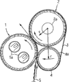
The present invention provides a fixing device and an image forming apparatus employing the fixing device. The fixing device comprises: a fuser roller 1 having a built-in heat source 1a therein and an elastic member 1c layered on the outer surface thereof; a pressure roller 2 to be pressed against the fuser roller 1; a heat-resistant belt 3 which is wound around the outer periphery of the pressure roller 2 and is sandwiched between the pressure roller 2 and the fuser roller 1 so as to travel; and a belt tensioning member 4 for tensioning the heat-resistant belt 3. The belt tensioning member 4 is arranged on the upstream side in the traveling direction of the heat-resistant belt 3 relative to the pressed portion of the fuser roller 1 and the pressure roller 2 and near the fuser roller 1 beyond the tangent L to the pressed portion to wrap the heat-resistant belt 3 around the outer periphery of the fuser roller 1 to form a nip. The simplification of the structure, reduction in size, and reduction in cost of the fixing device of fuser roller type are achieved. In addition, the warm-up time can be shortened. Further, the stress on a sheet medium is reduced, thereby preventing the deformation, such as curl and wrinkles, of the ejected sheet medium.
Description
Technical field
The present invention relates to a kind of fixing device and image processing system, wherein, described fixing device has: heat fixing roll, its surface coverage resilient material, built-in heating source; Backer roll is pressed against on the described heat fixing roll; Heatproof zone is wound on the periphery of described backer roll, and is clamped between described backer roll and the described heat fixing roll mobile; And the band tension part, being used for tensioning and supporting described heatproof zone, described fixing device carries out photographic fixing to the unfixed toner image that is formed on the sheeting.
Background technology
In image processing systems such as duplicating machine, Printers and Faxes machine, as a kind of to heating roller-type fixing device on the transfer materials, that unfixed toner image is carried out the Contact Heating photographic fixing, a kind of fixing device (with reference to No. the 3084692nd, Jap.P.) has been proposed, wherein, be provided with: heat fixing roll, its surface coverage resilient material and built-in heating source can rotate; Heatproof zone is supported by the tensioning of a plurality of backing roll institute; Pressure apparatus, the heatproof zone of only reeling around the heat fixing roll of predetermined angular scope forms clamp area, simultaneously in the exit of this clamp area, applies the local pressure greater than other parts, makes the distortion of heat fixing roll surface elasticity material production; Make sheeting easily discharge from clamp area.
In existing fixing device, produce distortion on the surface of heat fixing roll in advance because pass through the pressure apparatus that possessed, so, decontrol its surface deformation from surperficial state of contact moment of toner and heat fixing roll in the exit of clamping zone.Therefore, when sheeting when clamp area is discharged from, the adhesion of toner and heat fixing roll is reduced, be rolled onto on the heat fixing roll thereby suppressed sheeting, like this, even soft recording chart also can be easily breaks away from from the exit of band clamp area.Said apparatus by this method, saved always the essential stripper that adopts.
In addition, a kind of fixing device (with reference to Japanese patent gazette special fair 6-40235) is disclosed, specifically be, the clamp area length that formation contacts with roller according to the pressure bending of setting between the roller, make the sheeting that is loading unfixed toner image by photographic fixing in the middle of the clamp area, wherein, select first speed or second speed to drive this roller as the roller actuating speed that is fit to the sheeting characteristic.
In addition, a kind of fixing device (with reference to Japanese patent laid-open 8-262903) is disclosed again, specifically be, for its surface coverage resilient material, built-in heating source and the heat fixing roll that rotates disposes pressure block (pad) in the inboard of endless belt with non-rotating state, thus this endless belt that the tensioning supporting movement under contact condition, and this endless belt is pressed on the heat fixing roll, form clamp area, simultaneously, make the distortion of heat fixing roll surface elasticity layer; Like this, between heat fixing roll and endless belt by being formed with the sheeting of unfixed toner image, thereby on sheeting, carry out the hot photographic fixing of toner.The advantage of this device is, because pressure block so be difficult for distributing the heat that transmits from heat fixing roll, that is to say, less the heat of chargeable heat fixing roller with the non-rotating state configuration.
But, in the structure of the fixing device of No. the 3084692nd, above-mentioned Jap.P., because pass through pressure apparatus, only on the heat fixing roll of the angular range that can form clamp area, reel support by a plurality of support rollers tensionings, heatproof zone movably, simultaneously, apply very big local pressure to the exit of clamping zone and drive, so this just needs a plurality of rollers that are used to support and bearing thereof.Especially, at this moment the girth of heatproof zone can be elongated, and fixing device becomes complicated, huge simultaneously, and cost also uprises.The fixing device structure of complexity, maximization and high cost will inevitably make image processing system complexity, maximization and the cost height that loads this fixing device.
And, though heatproof zone and built-in heating source, rotatable heat fixing roll between clamp area be heated, but for for this structure of a plurality of support rollers tensionings heatproof zone that support, that girth is elongated, when on the path of heatproof zone at defined when mobile, heat is consumed by a plurality of support rollers, thereby, corresponding perimeter length, natural heat dissipation will strengthen.Therefore, the time that reaches set point of temperature will be elongated, and can photographic fixing from being energized to, and required preheating time is also with elongated, yet that this is us is undesirable.
Also have, for heat fixing roll, only can form the angle coiling heatproof zone of clamp area, and apply the local pressure bigger in the exit of clamp area than other parts, thereby the elastic layer at heat fixing roll generates distortion, though this structure can suppress sheeting coiling heat fixing roll preferably, yet, the sheeting of discharging along the distortion of elastic layer also can curl thereupon, or produces distortion such as fold owing to partial high pressure.
In addition, special fair 6-40235 that announce in Japanese patent gazette, to cooperate the sheeting characteristic to select the roller actuating speed be in the device of first speed or second speed, not only there are problems such as its roller thermal capacity big, required preheating time of length, and through the sheeting between the long clamp area that forms by pressure coiling roller, the same with aforesaid device, because the stress of this pressure is bigger, and cause distortion such as curling and fold.
In addition, described Japanese patent gazette spy opens flat 8-262903 device, with non-rotating state configuration pressure block, make heat be difficult for dispersing from heat fixing roll, the heat of less chargeable heat fixing roller, thereby be a kind of Eco-power fixing device, but, when preheating, exist heat to pass to pressure block through the endless belt, and make elongated problem preheating time from heat fixing roll.In addition, move, need 3 at least with upper roller for making belt, thus the problem that causes device to maximize.
Summary of the invention
The objective of the invention is to, make simplification, miniaturization and the cost degradation of hot-rolling type fixing device structure become possibility, and shorten preheating time.Another object of the present invention also is, reduces the stress to sheeting, curls or distortion such as fold thereby be suppressed to produce on the film condensation material of discharge.
To this, the present invention is a kind of fixing device, wherein, possesses:
Heat fixing roll; And
Backer roll, it is pressed against on the described heat fixing roll through heatproof zone,
It is characterized in that,
Described heatproof zone is tensioned between the band tension part and described backer roll that is supported on slip, described band tension part is configured in movably, make the tangent line of described heatproof zone, on the position that described heat fixing roll one side is reeled from the extruding between described heat fixing roll and described backer roll.
In addition, the present invention is a kind of fixing device, wherein, possesses:
Heat fixing roll, built-in heating source;
Backer roll is pressed against on the described heat fixing roll;
Heatproof zone is wound on the periphery of this backer roll, and is clamped between described backer roll and the described heat fixing roll mobile; And
The band tension part is used for tensioning and supports described heatproof zone,
This fixing device carries out photographic fixing to the unfixed toner image that is formed on the sheeting,
It is characterized in that,
Described band tension part is configured in the upstream side of described heatproof zone moving direction movably with respect to the place of pressing between described heat fixing roll and the described backer roll, and be positioned at described heatproof zone and reel to described heat fixing roll, thereby form on the position of clamp area from the described tangent line that presses.
In addition, the present invention is a kind of fixing device, wherein, possesses:
Heat fixing roll, built-in heating source;
Backer roll is pressed against on the described heat fixing roll;
Heatproof zone is wound on the periphery of this backer roll, and is clamped between described backer roll and the described heat fixing roll mobile;
And the band tension part, be used for tensioning and support described heatproof zone,
This fixing device carries out photographic fixing to the unfixed toner image that is formed on the sheeting,
It is characterized in that,
Described band tension part is with respect to the place of pressing of described heat fixing roll and described backer roll, when being configured in the upstream side of described heatproof zone moving direction, described band tension part is and can supporting to the state of described heat fixing roll direction swing, in addition, described band tension part, be supported on swingably on the axle of described backer roll, or be supported on swingably on the axle different with the axle of described backer roll.
In the above-mentioned fixing device, it is characterized in that,
Described band tension part breaks away from described heat fixing roll and disposes, or, be pressed against on the described heat fixing roll and dispose, be pressed against the throw-on pressure of the throw-on pressure of the described band tension part on the described heat fixing roll less than described backer roll, during contact pressure between described heat fixing roll and the described heatproof zone distributes, the pressure maximum of described heat fixing roll and described backer roll institute crimping part.
In the above-mentioned fixing device, it is characterized in that,
Described band tension part can be slide unit, semilune parts, roller shape parts, and secondary transfer roller, and at one end or two ends have and make described heatproof zone contact and limit the projection of its position; Its feature also is, drives described backer roll, and described heat fixing roll through described heatproof zone along with driven, described backer roll has the big surface of resilient material hardness that is covered than described heat fixing roll surface.
In addition, its feature also is,
Make friction factor between described backer roll and the described heatproof zone greater than the friction factor between described band tension part and the described heatproof zone;
Make the winding angle of the winding angle of described backer roll and described heatproof zone greater than described band tension part and described heatproof zone; And
Make the diameter of the diameter of described backer roll greater than described band tension part.
Its feature also is, as the drive unit that drives described band tension part, have a plurality of rotational speeies, corresponding sheeting characteristic selects described rotational speed to drive, have first rotational speed and second rotational speed slower than this first rotational speed, and corresponding described sheeting characteristic is selected to drive, and, has the pick-up unit that detects described sheeting characteristic, in having loaded the sheeting traveling process of described unfixed toner image, detect the characteristic of sheeting, and corresponding described sheeting characteristic selects to drive, in addition, also have corresponding sheeting property settings and select the setting device of information, in the photographic fixing execution process instruction of the sheeting that has loaded described unfixed toner image, corresponding described sheeting characteristic is set, and selects to drive according to this setting content.
In addition, in the above-mentioned fixing device, its feature also is,
Dispose cleaning member, its sliding contact is in the inner peripheral surface of described heatproof zone, between described backer roll and described band tension part; Described heat fixing roll is that resilient material 2mm below form by the periphery cladding thickness that external diameter is, wall thickness is the tubing below the 2mm below the 60mm, backer roll by external diameter be below the 60mm, wall thickness is that tubing below the 2mm forms.
A kind of fixing device wherein, possesses:
Heat fixing roll, built-in heating source;
Backer roll is pressed against on the described heat fixing roll;
Heatproof zone is wound on the periphery of this backer roll, and is clamped between described backer roll and the described heat fixing roll mobile; And
The band tension part is used for tensioning and supports described heatproof zone,
This fixing device carries out photographic fixing to the unfixed toner image that is formed on the sheeting,
It is characterized in that,
With respect to described heat fixing roll, dispose described band tension part swingably, heatproof zone is wound on the heat fixing roll, thereby form the photographic fixing clamp area, simultaneously, when sheeting does not pass through, form the gap between described band tension part and the heatproof zone, and when sheeting passes through, the band tension part is pressed against on the heat fixing roll through sheeting, with respect to the place of pressing of described heat fixing roll and described backer roll,, perhaps dispose described band tension part in the downstream of described heatproof zone moving direction at the upstream side of described heatproof zone moving direction.
A kind of fixing device wherein, possesses:
Heat fixing roll, built-in heating source;
Backer roll is pressed against on the described heat fixing roll;
Heatproof zone is wound on the periphery of this backer roll, and is clamped between described backer roll and the described heat fixing roll mobile; And
The band tension part is used for tensioning and supports described heatproof zone;
This fixing device carries out photographic fixing to the unfixed toner image that is formed on the sheeting,
It is characterized in that,
With respect to the place of pressing between described heat fixing roll and the described backer roll, upstream side at described heatproof zone moving direction, dispose described band tension part swingably, and the heatproof zone of on heat fixing roll, reeling, thereby form the photographic fixing clamp area, simultaneously, if: the pressure of clamp area initial position is P1, the pressure that backer roll presses the place of pressing of heat fixing roll is P3, when the pressure between the described clamp area initial position and the place of pressing is P2, the relation of P1<P2<P3 is arranged then.
A kind of fixing device wherein, possesses:
Heat fixing roll, built-in heating source;
Backer roll is pressed against on the described heat fixing roll;
Heatproof zone is wound on the periphery of this backer roll, and is clamped between described backer roll and the described heat fixing roll mobile; And
The band tension part is used for tensioning and supports described heatproof zone;
This fixing device carries out photographic fixing to the unfixed toner image that is formed on the sheeting,
It is characterized in that,
With respect to the place of pressing between described heat fixing roll and the described backer roll, downstream at described heatproof zone moving direction, dispose described band tension part swingably, and the heatproof zone of on heat fixing roll, reeling, thereby form the photographic fixing clamp area, simultaneously, if: the pressure of clamp area end position is P1 ', the pressure that backer roll presses the place of pressing of heat fixing roll is P3, when the pressure between the described clamp area end position and the place of pressing is P2, the relation of P1 '<P2<P3 is arranged then.
In the above-mentioned fixing device, it is characterized in that,
Has this structure: when sheeting is obstructed out-of-date, form the gap between described band tension part and the heatproof zone, and when sheeting passed through, the band tension part was pressed against on the heat fixing roll through sheeting; Its feature also is, described band tension part, ordered about device by the swing of ordering about to the heat fixing roll direction and order about swing, the outside at described heatproof zone Width, with the heat fixing roll sliding contact, and be supported on swingably on the turning axle of described backer roll, or be supported on swingably on the axle different with the turning axle of described backer roll.
Description of drawings
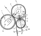
Fig. 1 is the embodiment figure of fixing device of the present invention.
Fig. 2 is the supporting construction figure that the band tension part of tensile force is provided to heatproof zone.
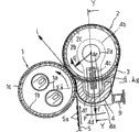
Fig. 3 is other embodiments figure of fixing device of the present invention.
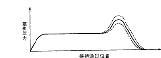
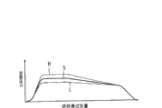
Fig. 4 is the photographic fixing pressure instance graph that changes by the position according to clamping.
Fig. 5 is the embodiment figure of fixing device of the present invention.
Fig. 6 is the key diagram that concerns between the position of tension part and the clamping zone.
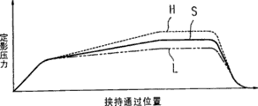
Fig. 7 is the variation diagram of clamping by position and photographic fixing pressure.
Fig. 8 is other embodiments figure of fixing device of the present invention, and wherein, tension part is arranged on the downstream of direction of belt travel.
Fig. 9 is the variation diagram of clamping when tension part is arranged on the downstream of direction of belt travel, fixing device by position and photographic fixing pressure.
Figure 10 is the key diagram that concerns between the position, downstream of tension part and the clamp area.
Figure 11 is that tension part adopts the cylinder material and it is arranged on other embodiments figure of direction of belt travel upstream side, fixing device of the present invention.
Figure 12 is that tension part adopts the cylinder material and it is arranged on other embodiments figure of direction of belt travel downstream, fixing device of the present invention.
Figure 13 dissects and sees in the past sectional view, other embodiments of expression fixing device of the present invention to the direction of arrow along the X among Figure 14-X face.
Figure 14 is the sectional view that dissects and see to the direction of arrow past along the Y among Figure 13-Y face.
Figure 15 is other embodiments figure of fixing device of the present invention, and wherein, Figure 15 A dissects and sees that to the direction of arrow in the past sectional view, Figure 15 B are to dissect and see sectional view in the past to the direction of arrow along the Y among Figure 15 A-Y face along the X among Figure 15 B-X face.
Figure 16 is other embodiments figure of fixing device of the present invention, and wherein, Figure 16 A dissects and sees that to the direction of arrow in the past sectional view, Figure 16 B are to dissect and see sectional view in the past to the direction of arrow along the Y among Figure 16 A-Y face along the X among Figure 16 B-X face.
Figure 17 is other embodiments figure of fixing device of the present invention, and wherein, Figure 17 A dissects and sees that to the direction of arrow in the past sectional view, Figure 17 B are to dissect and see sectional view in the past to the direction of arrow along the Y among Figure 17 A-Y face along the X among Figure 17 B-X face.
Figure 18 is the photographic fixing pressure instance graph that changes by the position according to clamping.
Figure 19 is other embodiments figure of fixing device of the present invention, and wherein Figure 19 A is a sectional view; Figure 19 B sees sectional view in the past along the Y among Figure 19 A-Y alignment direction of arrow.
Figure 20 is that the X-X face along Figure 19 A dissects and sees in the past sectional view, the detailed structure of expression Figure 19 to the direction of arrow.
Figure 21 removes heatproof zone local amplification sectional view afterwards in Figure 19 A.
Figure 22 is the view that heatproof zone 3 is installed in Figure 21.
Figure 23 be in Figure 22 sheeting by the time constitutional diagram.
Figure 24 is the feature description figure of present embodiment, Figure 24 A is a sectional view, Figure 24 B represents that for the photographic fixing pressure of clamping by the position, Figure 24 C represents the only photographic fixing pressure under the swing displacing force of band tension part 4, the photographic fixing pressure when Figure 24 D represents to assist (assist) swing displacing force.
Figure 25 is the variation of the fixing device of Figure 19, and Figure 25 A is a sectional view, and Figure 25 B is that the Y-Y alignment direction of arrow along Figure 25 A is seen sectional view in the past.
Figure 26 is the sectional view of the fixing device variation of Figure 19.
Figure 27 represents other embodiments of fixing device of the present invention, and Figure 27 A is a sectional view, and Figure 27 B sees sectional view in the past along the Y among Figure 27 A-Y alignment direction of arrow.
Figure 28 represent among Figure 27 sheeting not by the time state, Figure 28 A is the local amplification sectional view of Figure 27 A, Figure 28 B dissects along the X among Figure 28 A-X face, and sees in the past sectional view to the direction of arrow.
Figure 29 represent among Figure 27 sheeting by the time state, Figure 29 A is the local amplification sectional view of Figure 27 A, Figure 29 B dissects along the X among Figure 29 A-X face, and sees in the past sectional view to the direction of arrow.
Figure 30 is the example that is illustrated among Figure 29 the photographic fixing pressure that changes by the position according to clamping, wherein, Figure 30 A is a sectional view, when Figure 30 B represents the swing displacing force of subband tension part 4, photographic fixing pressure according to clip position, when Figure 30 C represents the swing displacing force of subband tension part 4, according to the photographic fixing pressure of sheeting.
Figure 31 is the variation of the embodiment of Figure 27, and Figure 31 A is a sectional view, and Figure 31 B is that the Y-Y alignment direction of arrow along Figure 31 A is seen sectional view in the past.
Figure 32 is other embodiments of image processing system of the present invention, one-piece construction typical section figure.
Figure 33 is other embodiments figure of the fixing device of the present invention when the band tension part is also used as secondary transfer roller.
Figure 34 has carried to be also used as other embodiments figure fixing device, image processing system of the present invention of secondary transfer roller with tension part.
Embodiments of the present invention
Below, with reference to description of drawings form of implementation of the present invention.
Fig. 1 is the embodiment figure of fixing device of the present invention.Wherein, 1 is that heat fixing roll, 1a are that halogen lamp, 1b are that roller stock, 1c are that resilient material, 2 is that backer roll, 3 is that heatproof zone, 4 is that projection, 5 is that sheeting, 5a are that unfixed toner image, 6 is that cleaning member, L are the tangent line that presses the place for being with tension part, 4a.
In Fig. 1, heat fixing roll 1 use external diameter as below the 60mm, wall thickness as the tubing below the 2mm as roller stock 1b, and cladding thickness is that resilient material 1c below the 2mm forms around it, and, in roller stock 1b inside as heating source, built-in halogen lamp 1a, in addition, this heat fixing roll can rotate.Backer roll 2 by external diameter be below the 6mm, wall thickness is that tubing below the 2mm forms, and is provided with respect to heat fixing roll 1, with the pressure crimping of heat fixing roll 1, can rotate with regulation.
In order stably to drive heatproof zone 3 with backer roll 2 by backer roll 2 and 4 tensionings of band tension part, can make friction factor between backer roll 2 and the heatproof zone 3 greater than the friction factor between band tension part 4 and the heatproof zone 3, but at this moment, because the intrusion of foreign matter or wearing and tearing etc. make the friction factor instability sometimes.At this situation, if make the winding angle of the winding angle of backer roll 2 and heatproof zone 3 greater than band tension part 4 and heatproof zone 3, and the diameter that backer roll 2 is set is during greater than the diameter of band tension part 4, the length that band tension part 4 slides with respect to heatproof zone 3 will shorten, therefore can avoid the influence of labile factors such as the variation in elapsed time and external disturbance, thereby can stably drive heatproof zone 3 by backer roll 2.
Fig. 2 is the supporting construction exemplary plot that applies the band tension part of tensile force to heatproof zone.As shown in Figure 2, supporting construction as band tension part 4, be provided with from the end of band tension part 4, the bossing 4b that extends in parallel at the direction of principal axis of backer roll 2, with the bossing 4c that extends to the axis direction of backer roll 2, bossing 4b is inserted in the patchhole of erecting frame 7, bossing 4c is inserted in the groove of supporter 4e, and obtaining tensile force by spring 4d, wherein said supporter 4e can be supported on the turning axle 2a of backer roll 2 with rotating freely.The cooperation of the patchhole of bossing 4b and erecting frame 7 can apply at the elastic force of spring 4d on the direction f and to move, but can not near or away from the direction of heat fixing roll on move.In addition, for A-A line axle, as shown in the figure of axle that connects backer roll 2 and band tension part 4, by groove, this elastic force action direction f can be inclined to the close direction of heat fixing roll 1, perhaps also can be inclined to from heat fixing roll 1 away from direction.
As band tension part 4, when using the heatproof zone slide unit, owing to be not rotary part, so do not need bearing, simple thereby supporting construction becomes.Add by being with tension part to be made as the first quarter moon shape, the direction that first quarter moon can be lost can be configured near backer roll 2 sides so to greatest extent towards the configuration of backer roll 2 sides.Thus, can also shorten the girth of heatproof zone 3.Thereby, can obtain hot-rolling type fixing device simple in structure, small-sized, low price.
Also have, heatproof zone 3 is because move on the path of required minimum zone, therefore at the rotatable heat fixing roll 1 of built-in heating source and the heated heatproof zone 3 of clamp area therebetween, the heat that is consumed when mobile on prescribed path can be suppressed on the minimum limit, simultaneously, because all length, thus the temperature that causes because of natural heat dissipation descend seldom, thereby can shorten from beginning to be energized to the preheating time that obtains required fixing temperature.
Fig. 3 is other embodiments of fixing device of the present invention figure, and Fig. 4 is the photographic fixing pressure exemplary plot that changes by the position corresponding to clamping.In the embodiment shown in Fig. 1, Fig. 2, band tension part 4 has adopted half moon heat-resisting slide unit, still, as shown in Figure 3, band tension part 4 ' also can use the cylinder material.Band tension part 4 ',, also can make its rotation so can be used as slide unit because be drum part.By can rotate freely ground support belt tension part 4 ', can make between backer roll 2 and the heatproof zone friction factor greater than the band tension part 4 ' and heatproof zone between friction factor, thereby for heatproof zone 3, can be enough backer roll 2 and the 4 ' tensioning of band tension part, and with backer roll 2 stabilized driving.
In addition, in embodiment shown in Figure 3, its band tension part 4 ' not gently to be pressed on the heat fixing roll 1, but the disengaging configuration.That is, band tension part 4 ' be configured in is with respect to the upstream side of the moving direction of the heatproof zone 3 of clamp area initial position.So this moment is if the direction that will dispose to close heat fixing roll moves, the initial position that will make clamp area is side shifting more upstream, so just can increase the length of clamp area, otherwise, if move this configuration, make it to leave heat fixing roll 1, just can shorten clamp area length.
Certainly, in Fig. 1, embodiment shown in Figure 2, also can similarly break away from configuration band tension part 4, and in embodiment shown in Figure 3 from heat fixing roll 1, also can on heat fixing roll 1, gently be press-fitted put band tension part 4 '.This disengaging from heat fixing roll 1 disposed the structure of being with tension part 4, in clamping zone, just have certain photographic fixing pressure from the clamp area initial position, and on end position, the pressure that is produced by backer roll 2 makes photographic fixing pressure become bigger.
In addition, drive with backer roll 2, when making band tension part 4,4 ' slips, also can support belt tension part 4,4 ', make and be with tension part 4,4 ' on approaching, the direction left, freely swing with respect to heat fixing roll 1.With band tension part 4,4 ' when making the structure that to swing, by drive because of the rotation of backer roll 2 driven heatproof zone 3 and band tension part 4,4 ' between the friction force effect, heatproof zone 3 and band tension part 4,4 ' will stop under the equilibrium state, that is, thus the equilibrium state that between oscillatory forces that swing on the direction of heat fixing roll 1 is produced by described friction force and heatproof zone 3 are crimped on throw-on pressure on the heat fixing roll 1, reaches.
Just, load the sheeting 5 of unfixed toner image 5a, no matter be the state that is in by between heat fixing roll and the heatproof zone 3, still be in the state that does not pass through, or even no matter the thickness of sheeting is thick, and is still thin, the throw-on pressure of heatproof zone 3 and heat fixing roll 1 crimping all is uniformly, is uniform to the stress of the sheeting 5 that passes through.Therefore, on the sheeting that unfixed toner image 5a is carried out being discharged after the photographic fixing, do not produce the distortion of sheetings such as fold.And between heatproof zone 3 and heat fixing roll 1, according to set heatproof zone 1 and band tension part 4,4 ' between friction force, can obtain suitable crimp force.
Fig. 4 has represented situation about changing by position and photographic fixing power corresponding to the clamping of these structures.When Fig. 4 A represents to be fixed with tension part, the sheeting (solid line) of thicker sheeting (dotted line), standard thickness, the photographic fixing pressure changing of thin sheeting (double dot dash line).Here, the photographic fixing pressure of thicker sheeting rises at the clamp area initial position, and as a whole, according to the thickness of sheeting, photographic fixing pressure is different.When Fig. 4 B represents can swing with tension part, the sheeting (solid line) of thicker sheeting (dotted line), standard thickness, the photographic fixing pressure changing of thin sheeting (double dot dash line).Here, the thickness of photographic fixing pressure and sheeting is irrelevant, is the size of defined.When Fig. 4 C represents the position of transfer zone tension part, the sheeting (solid line) of thicker sheeting (dotted line), standard thickness, the photographic fixing pressure changing of thin sheeting (double dot dash line).Here, because the conversion of clamp area initial position, so though produce certain pressure differential, its difference is very little.Therefore, though corresponding to the kind of sheeting, photographic fixing pressure is different, can pass through transfer zone tension part 4,4 ' the position, change clamp area length, thereby can adjust photographic fixing pressure.
The surface of the resilient material 1c of heat fixing roll 1 and the surface of heatproof zone 3, move with same rotating speed, and the unfixed toner image that is formed on the sheeting 5 carried out photographic fixing, but, the top ends of the surface of heatproof zone 3 or sheeting 5 is divided into when wavy, and it is unstable that the state when photographic fixing begins will become sometimes.Here, if at the initial position of clamp area, adopt when heatproof zone 3 gently is pressed in structure on the heat fixing roll 1, both sides become stable contact condition, thereby can carry out photographic fixing to unfixed toner image highly stablely.Tension part 4,4 ' coacting applies tensile force to heatproof zone 3 for backer roll 2 and band, and it is wound on the heat fixing roll 1, thereby forms clamp area, therefore, can easily form long clamp area, thereby, device simple in structure, small-sized, low price can be obtained.
Fig. 5 is other embodiments figure of fixing device of the present invention, and Fig. 6 is the key diagram that concerns between band tension part and the clamping zone, and Fig. 7 is the variation diagram of clamping by position and photographic fixing pressure.Among the figure, the 7th, framework, 7a are pilot holes, 7b is a bearing, the 8th, tensioning support component, 8a are the springs that applies tensile force, L is the tangent line that presses the place.
In Fig. 5, it is that 60mm is following, wall thickness is that the following tubing of 2mm is as roller basic element of character 1b that heat fixing roll 1 adopts outer dia, and cover the resilient material 1c below the 2mm and form in its periphery, and the built-in halogen lamp 1a of portion is as heating source within it, and described heat fixing roll 1 is rotatable simultaneously.Backer roll 2 by outer dia be below the 60mm, wall thickness is that tubing below the 2mm forms, and be configured on the position of heat fixing roll 1, and its turning axle rotatably is supported on the bearing 7b of framework 7, in addition, described backer roll 2 is pressed against on the heat fixing roll 1 with authorised pressure F through heatproof zone 3.
Band tension part 1 for example is half moon band slide unit, be configured on the position that forms clamp area, wherein, described clamp area is by being embedded on the interior week that contacts heatproof zone 3 with tension part 1, cooperate with each other tensioning heatproof zone 3 with backer roll 2, and apply tensile force f to heatproof zone 3, simultaneously, heatproof zone 3 is wound up on the heat fixing roll 1 and forms.That is, band tension part 4 is configured in, and heatproof zone 3 is from the tangent line L that presses of heat fixing roll 1 and backer roll 2, on the position that a side of heat fixing roll 1 is reeled.Band tension part 4 is provided with projection 4a in its one or both ends, when heatproof zone 3 to a lateral deviation from the time, thereby projection 4a contacts with heatproof zone 3 and limits departing from of heatproof zone 3.In addition, the two ends of band tension part 4 are provided with guiding parts 4b and tensile force applies parts 4c, make band tension part 4 be embedded in interior week of heatproof zone 3, and apply tensile force to heatproof zone 3.Guiding parts 4b, for example become the pin shape outstanding on the direction parallel with turning axle 2a, and coincide with the pilot hole 7a of slidably state and framework 7, tensile force applies the inboard that parts 4c is configured in tensioning heatproof zone 3, promptly on the extended position of backer roll 2 sides, and apply spring 8a by tensile force and apply tensile force to the direction that deviates from backer roll 2.
As shown in the figure, in the fixing device of the present invention, with respect to authorised pressure F, the backer roll 2 that process heatproof zone 3 presses to heat fixing roll 1, the band tension part 4 of tensioning heatproof zone 3 is configured in, make heatproof zone 3 from the tangent line L that presses between heat fixing roll 1 and the backer roll 2 on the position that heat fixing roll 1 one sides are reeled.This position is by the pilot hole 7a decision of framework 7, wherein, pilot hole 7a is on the direction that band tension part 4 allows to slide, outside from the bearing 7b of the turning axle 2a that supports backer roll 2, be oblong shape, thereby check strap tension part 4 can't move it on close, as to leave heat fixing roll 1 direction.Corresponding therewith, tensile force applies in the groove that parts 4c is placed on tensioning support component 8, applies spring 8a by the tensile force of establishing within it, is the center with the turning axle 2a of backer roll 2, outwards exerts pressure.The action direction of tension force f is limited in by oval direction, links on A-A line axle, shown in the figure of the axle of backer roll 2 and band tension part 4, but for this A-A line, also can make oval axially near or the direction of leaving heat fixing roll 1 tilt.
In order stably to drive heatproof zone 3 with backer roll 2 by backer roll 2 and 4 tensionings of band tension part, can make friction factor between backer roll 2 and the heatproof zone 3 greater than the friction factor between band tension part 4 and the heatproof zone 3, but at this moment, because the intrusion of foreign matter or wearing and tearing etc. make the friction factor instability sometimes.At this situation, if make the winding angle of the winding angle of backer roll 2 and heatproof zone 3 greater than band tension part 4 and heatproof zone 3, and the diameter that backer roll 2 is set is during greater than the diameter of band tension part 4, the length that band tension part 4 slides with respect to heatproof zone 3 will shorten, therefore can avoid the influence of labile factors such as the variation in elapsed time and external disturbance, thereby can stably drive heatproof zone 3 by backer roll 2.
In the fixing device of the present invention, allocation position according to the band tension part 4 of setting described tensioning heatproof zone 3, heatproof zone 3 is reeled to a side of heat fixing roll 1 from the tangent line L that presses between heat fixing roll 1 and the backer roll 2, therefore, as shown in Figure 6, can freely change the length of clamp area by changing described allocation position.For example from solid line shown in Figure 6, make band tension part 4 leave heat fixing roll 1, and on L, when tension part 4 is with in the configuration of dashdotted position, the winding angle that heatproof zone 3 is wound up on the heat fixing roll 1 diminishes, thereby, clamp area length shortens, otherwise, if make band tension part 4 near heat fixing roll 1, on the H line, the position of double dot dash line configuration band tension part 4, when making it be pressed against on the heat fixing roll 1 gently, the winding angle that heatproof zone 3 is wound up on the heat fixing roll 1 becomes big, thereby clamp area length is elongated.
Also have, drive with backer roll 2, when band tension part 4 is slided, can support belt tension part 4, it can freely be swung on approaching, as to leave heat fixing roll 1 direction.When band tension part 4 is made the structure that can swing, rotation by backer roll 2 drives the heatproof zone 3 that driven and the friction force between the band tension part 4, heatproof zone 3 and band tension part 4 are swung to the direction of heat fixing roll 1, and stop under the equilibrium state of the crimp force of heat fixing roll 1 crimping at the oscillatory forces and the heatproof zone 3 that are produced by described friction force.
Promptly, because swinging structure is arranged, load the sheeting 5 of unfixed toner image 5a, no matter be the state that is in by between heat fixing roll 1 and the heatproof zone 3, still be in not by state, even, the thickness of sheeting no matter, the crimp force of heatproof zone 3 and heat fixing roll 1 crimping all is uniformly, also is uniform to sheeting 5 applied pressures that pass through.Therefore, for the sheeting of after unfixing toner figure 5a is by photographic fixing, being got rid of, can eliminate the distortion of the sheetings such as fold above it.And the configuration by band tension part 4 can be wound up into heatproof zone 3 on the heat fixing roll 1, therefore, the friction force that heatproof zone 3 and band tension part are 4 can make the crimp force of 1 of heatproof zone 3 and heat fixing roll change, thereby, can acquire suitable crimp force by the setting of friction force.
For example, though corresponding to the kind difference of sheeting, photographic fixing pressure is difference to some extent, by the position of transfer zone tension part 4, changes clamp area length, thereby can adjust photographic fixing pressure.For example in Fig. 6, if change the configuration of band tension part 4 it is left from heat fixing roll 1, when being positioned on the non-contacting position, the angle that heatproof zone 3 is wound up on the heat fixing roll 1 will diminish, and clamp area length also can shorten,
After making the position of being with tension part 4 further deviate from backer roll 2 (moving to the diagram below), when turning back on the close position of heat fixing roll 1, the angle that heatproof zone 3 is wound up into heat fixing roll will become greatly, and clamp area length also can be elongated.Illustrated state is that band tension part 4 gently is pressed in the state on the heat fixing roll.
Especially, at thicker sheeting, for example on the OHP thin slice, when the toner image of coloured image is carried out photographic fixing, if versicolor toner fails fully to melt photographic fixing, so, on thin slice during direct viewing, though be the coloured image of expection, directly see on its projection image and the OHP thin slice pass by different not present desired coloured image.Therefore, when coloured image is carried out photographic fixing, in order not produce this bad phenomenon, countermeasures such as the pressure when being necessary to take to increase photographic fixing, the heating that increases toner, thawing time.Yet, excessive if photographic fixing pressure adds, on thin slice, be easy to generate fold and curl wait distortion.In addition, when reducing the speed of photographic fixing operation, will reduce the efficient that image forms for the heating that increases toner, thawing time.At this moment because, when reducing its speed,, must reduce the speed of all operations from development operation before this because the photographic fixing operation is a last operation.
In any embodiment of the present invention, because be wound up into configuration band tension part 4 on the position on the heat fixing roll 1 at heatproof zone 3, so position according to its configuration, can not reduce operating speed, and form suitable clamp area, and can guarantee heating, the thawing time of sufficient toner, thereby can realize the miniaturization of fixing device with simple structure.And, for the backer roll on being pressed against heat fixing roll 12, only need apply the throw-on pressure of necessary appropriateness, just can make the toner surface on the thin slice become level and smooth, in addition, also can produce large deformation at the place of pressing by very big throw-on pressure as conventional device, therefore clamp area need not be kept, thereby the distortion of the sheetings such as gauffer in the photographic fixing operation can be prevented.
When Fig. 7 A represents to be with tension part 4 to be fixed, the sheeting (solid line) of thicker sheeting (dotted line), standard thickness, the photographic fixing pressure changing of thin sheeting (double dot dash line).In the thicker sheeting,, the photographic fixing pressure of clamp area initial position is risen, and as a whole, according to the thickness of sheeting, photographic fixing pressure is different by light pressure zone tension part 4.For being with the direct position contacting of tension part 4 and heat fixing roll 1, promptly, the structure of configuration band tension part 4 on the position of leaving heat fixing roll 1, in clamping zone, from clamp area initial position photographic fixing pressure is certain amount, and at the clamp area end position, because the roof pressure of backer roll 2, it is big that photographic fixing pressure becomes.When Fig. 7 B represents to be with tension part to swing, the sheeting (solid line) of thicker sheeting (dotted line), standard thickness, the photographic fixing pressure changing of thin sheeting (double dot dash line).At this moment, the thickness of photographic fixing pressure and sheeting is irrelevant, is the size of defined.Fig. 7 C represents the position of transfer zone tension part 4, thereby change heatproof zone when angle (clamping zone) that heat fixing roll is reeled, the sheeting (solid line) of thicker sheeting (dotted line), standard thickness, the photographic fixing pressure changing of thin sheeting (double dot dash line).Though produce pressure differential this moment, because the conversion of clamp area initial position, its difference becomes very little.
Fig. 8 is other embodiments figure of of the present invention fixing device of band tension part when being arranged on the downstream of direction of belt travel, Fig. 9 is when the band tension part is arranged on the downstream of moving direction, the variation diagram of the clamping of fixing device by position and photographic fixing pressure, and Figure 10 is with tension part to be arranged on the key diagram that concerns between position, downstream and the clamp area.
In the above-described embodiment, though will be configured in the upstream side of heatproof zone 3 moving directions with tension part 4,, opposite, in other embodiments shown in Figure 8, band tension part 4 is configured in the downstream of heatproof zone 3 moving directions.The surface of the resilient material 1c of heat fixing roll 1 and the surface of heatproof zone 3, move with same rotating speed, the unfixed toner image that is formed on the sheeting 5 is carried out photographic fixing, but, the top ends of the surface of heatproof zone 3 or sheeting 5 is divided into when wavy, and the photographic fixing initial state is unstable sometimes.And in the present embodiment, initial position in clamp area, backer roll 2 is through heatproof zone 3, press heat fixing roll 1, even therefore the top ends of heatproof zone 3 and sheeting 5 is divided into wavy, both sides also can keep stable contact condition, thereby can carry out highly stable photographic fixing to unfixed toner image.
Fig. 9 is the situation of change figure of the clamping of present embodiment by position and photographic fixing pressure, when Fig. 9 A represents to be with tension part 4 to be fixed, the sheeting (solid line) of thicker sheeting (dotted line), standard thickness, the photographic fixing pressure changing of thin sheeting (double dot dash line).At this moment, as a whole, according to the thickness of sheeting, though photographic fixing pressure is different, but its difference is very little, and, when band tension part 4 is pressed gently, have only under the situation of thicker sheeting, slightly rise at clamp area end position photographic fixing pressure, and make when being with tension part 4 from heat fixing roll 1 disengaging formation tangent line clamp area, as shown in the figure, just there is not the rising part of clamp area end position.Clamping zone when Fig. 9 B represents the position of transfer zone tension part 4 is by the photographic fixing pressure changing of position, for example as shown in figure 10, corresponding to the sheeting (solid line) of thicker sheeting (dotted line), standard thickness, thin sheeting (double dot dash line), the position of transfer zone tension part 4.At this moment, because the conversion of clamp area end position, so though produce pressure differential, its difference becomes very little.
In above-mentioned various embodiments, as band tension part 4, use the band slide unit, rather than rotary part, therefore do not need bearing etc., supporting construction to become simple.And, will be with tension part 4 to make the first quarter moon shape, and the direction that its first quarter moon loses will be disposed towards backer roll 2 sides, so can be to greatest extent near backer roll 2.Can also shorten the girth of heatproof zone 3 thus.Thereby can obtain hot-rolling type fixing device simple in structure, small-sized, low price.
Also have, heatproof zone 3 is because move on the path of required minimum zone, therefore at the rotatable heat fixing roll 1 of built-in heating source and the heated heatproof zone 3 of clamp area therebetween, the heat that is consumed when mobile on prescribed path can be limited on the minimum limit, simultaneously, because all length, thus the temperature that causes because of natural heat dissipation descend seldom, thereby can shorten from beginning to be energized to the preheating time that obtains required fixing temperature.
Figure 11 is that tension part adopts the cylinder material and it is arranged on other embodiments figure of direction of belt travel upstream side, fixing device of the present invention.Figure 12 is other embodiments figure that the band tension part is arranged on the fixing device of the present invention of backer roll both sides.
In Figure 11, band tension part 4 ' be different from the half moon band tension part 4 in the above-mentioned embodiment, but adopt the circle roller member, be configured in the moving direction upstream side of heatproof zone 3.Otherwise, also can be with by the band tension part 4 that constitutes of circle roller ' the be configured in moving direction downstream of heatproof zone 3.In addition, can rotate freely ground support belt tension part 4 ', and, by rotate freely ground support belt tension part 4 ', can make the band tension part 4 ' and heatproof zone 3 between friction factor less than the friction factor between backer roll 2 and the heatproof zone, can also stably drive heatproof zone 3 with backer roll 2.
In addition, in described various embodiments, with respect to backer roll 2, band tension part 4,4 ' be configured in the moving direction upstream side of heatproof zone 3 or any side in downstream, yet, as shown in figure 12, also can be configured in the upstream and downstream both sides.By this structure, with the band tension part 4,4 ' either or both gently be pressed on the heat fixing roll 1, thereby can apply required, suitable throw-on pressure with 2 pairs of heat fixing rolls 1 of backer roll, simultaneously, can in other clamping zone, apply uniform photographic fixing pressure.In addition, with the band tension part 4,4 ' in one gently be pressed on the heat fixing roll 1, and another is moved away from heat fixing roll 1, it is not contacted, and, as solid line, double dot dash line are represented, can change clamp area length by in the distance of discontiguous side conversion with heat fixing roll 1.
For the unfixed toner image 5a that is formed on the sheeting 5 is carried out stable photographic fixing, must heat fully, melt unfixed toner image 5a, and then photographic fixing, thus, the time and the thawing time that reach preferred temperature are essential, but in the present embodiment, in order to make clamp area length elongated, do not need to take to make the resilient material 1c that covers on the heat fixing roll 1 to produce very large deformation, resilient material 1c increases the method for clamp area length, so can be a laminate structure.Even not by setting the throw-on pressure of backer roll 2 very big, make resilient material 1c produce very large deformation, also can obtain sufficient clamp area, so, the sheeting 5 that loads unfixed toner image 5a is by between heat fixing roll 1 and the heatproof zone 3 time, and the suffered pressure of sheeting 5 is very little, therefore, can be suppressed on the sheeting 5 of being discharged after the unfixed toner image 5a photographic fixing, produce the distortion of sheetings such as curling and gauffer.
Thereby, not only do not need to improve the mechanical stiffness of hot-rolling type fixing device, and can make the thickness attenuation of heat fixing roll 1, can also improve the firing rate of heating source in addition to heatproof zone 3.In addition, same, the thickness of backer roll 2 also can attenuation, thereby can constitute the little structure of thermal capacity, and therefore, the absorption of 3 pairs of heats of heatproof zone tails off, and then, can shorten obtaining temperature required and preheating time can photographic fixing from beginning to be energized to.
Can reach that the length, the restriction heatproof zone 3 that shorten heatproof zone 3 absorb minimal heat, the structure that reduces the purpose that the temperature that caused by natural heat dissipation descends is, make heatproof zone 3 be rolled onto band tension part 4,4 ' on length be rolled onto length on the backer roll 2 less than heatproof zone 3.Perhaps said structure is, make heatproof zone 3 be rolled onto band tension part 4,4 ' on angle be rolled onto angle on the backer roll 2 less than heatproof zone 3, be again, make band tension part 4,4 ' diameter less than the diameter of backer roll 2.As previously mentioned, adopt to shorten the girth of heatproof zone 3, when being allowed to condition at this structure that moves on the minimum necessary path, can obtain following many effects: promptly, make simple in structure, small-sized, the low price of hot-rolling type fixing device, can be limited in and the heated heatproof zone 3 of clamp area of 1 of heat fixing roll, on prescribed path, absorb minimum heat when mobile, the temperature that minimizing causes because of natural heat dissipation descends, and can shorten to obtain temperature required and preheating time that can photographic fixing etc. from beginning to be energized to.
Then the control to fixing device describes, wherein, as drive unit, in order to drive heat fixing roll 1 and backer roll 2 has a plurality of rotational speeies, two rotational speeies are at least also arranged, and,, select first rotational speed or drive heat fixing roll 1 and backer roll 2 than its second slow rotational speed corresponding to the characteristic of sheeting.In the pick-up unit of configuration detection sheeting characteristic, also be provided with the setting device of selection information such as basis sheeting property settings rotational speed in advance, thereby, in the traveling process of the sheeting 5 that loads unfixed toner image 5a, detect the sheeting characteristic, and in the photographic fixing execution process instruction of the sheeting 5 that loads unfixed toner image 5a, characteristic according to sheeting is set, and corresponding setting content selects rotational speed to drive.As establishing method, before the photographic fixing instruction manipulation, can carry out manual operation to the interlock part of hot-rolling type fixing device, perhaps can carry out operated from a distance by electric signal.Equally, kind that also can corresponding sheeting changes the position of superincumbent Fig. 6, band tension part illustrated in fig. 10.
Load the sheeting 5 of unfixed toner image 5a, must be applicable to, the sheeting as paper etc., the thicker sheeting of big thermal capacity, transparent sheeting multiple uses such as (OHP sheetings).Compare with general sheeting, especially for the sheeting of sandwich constructions such as the big thicker sheeting of thermal capacity, envelope or transparent sheeting (OHP sheeting) etc., need certain thawing time, fully melt unfixed toner image 5a, on sheeting, carry out photographic fixing.At this moment, the characteristic of corresponding sheeting is selected first rotational speed or is driven heat fixing roll 1 and backer roll 2 than its second low rotational speed, therefore can normally melt unfixed toner image 5a, thereby can realize the photographic fixing expected.
In addition, even select first rotational speed or second rotational speed to drive, because when the sheeting 5 of loading unfixed toner image 5a passes through between heat fixing roll 1 and heatproof zone 3, sheeting 5 pressures that pass through are very little and constant, so, for the sheeting 5 of after unfixed toner image 5a photographic fixing, being discharged, can restrain the distortion of sheetings such as fold.Thereby, not only do not need to improve the mechanical stiffness of hot-rolling type fixing device, and can make the thickness attenuation of heat fixing roll 1, can also improve the firing rate of heating source in addition to heatproof zone 3.In addition, same, the thickness of backer roll 2 also can attenuation, thereby can constitute the little structure of thermal capacity, and therefore, the absorption of 3 pairs of heats of heatproof zone tails off, and then, can shorten obtaining temperature required and preheating time can photographic fixing from beginning to be energized to.
In addition, as the driving method that changes rotational speed selectively, relatively be fit to adopt methods such as for example changing the CD-ROM drive motor revolution selectively.
Structure in the present embodiment is as follows: the profile of heat fixing roll 1 is, diameter is that (φ) 25, wall thickness are that the thickness of 0.7mm, resilient material 1c is 0.5mm; The profile of backer roll 2 is that diameter is that (φ) 25, wall thickness are 0.7mm; The throw-on pressure of heat fixing roll 1 and backer roll 2 is less than 10kg, and clamp area length is 10mm, and heating source is built-in 1000W column halogen lamp 1a, and be 30sec its preheating time.
Though the profile of heat fixing roll and backer roll is the minor diameter structure of φ 25, the sheeting that common toner image is carried out after the photographic fixing can not be wound up on heat fixing roll and the backer roll, does not therefore need to force the stripping off device of peeling sheet material.In addition, the toner image of the overlapping 4 kinds of colors of the formation of coloured image forms, so under the situation of photograph image, toner layer forms thicker unfixed toner image, so the sheeting after the photographic fixing is wound up on the heat fixing roll easily.Yet, in the present embodiment, in when, sheeting after the photographic fixing taking place reeling phenomenon on the heat fixing roll, though heatproof zone is drawn towards heat fixing roll one side through sheeting,, at the end position of clamp area, pressurized roller of heatproof zone and band tension part support towards the direction tensioning that breaks away from heat fixing roll, therefore, by the opposite action of this direction, prevent that sheeting after the photographic fixing from reeling on the heat fixing roll.
In the fixing device that constitutes by above-mentioned embodiment, with heat fixing roll or backer roll as driven roller, but this moment, in order to realize stable driving, preferably with hard roller as drive part, and with soft roller as secondary part.Backer roll 2 at its periphery heatproof zone 3 of reeling, and drives to the resilient material 1c crimping heatproof zone 3 that covers heat fixing roll 1 surface, and 1 one-tenth driven structure of heat fixing roll.Backer roll 2 is because determine heatproof zone, immediate shipment to carry the transfer rate of the sheeting 5 of unfixed toner image 5a, so have at least than the hard surface of resilient material 1c that covers hot fixed roll 1 surface.Thereby, can not deform, drive with stable transfer rate.
When projection 4a is arranged on an end of band tension part 4, can dispose backer roll 2 and band tension part 4, make their position relation allow heatproof zone 3 rely on a side, auxiliary heatproof zone 3 also can be set at the opposite side of heatproof zone 3, make it rely on the device of a side.In addition, when the two ends of band tension part 4 were provided with projection 4a, though in the projection interval at two ends, heatproof zone 3 can produce crooked, if but make the interval of two ends projection and the width of heatproof zone 3 become best structural relation, practical application does not just have problem.
Figure 13 and Figure 14 represent other embodiments of fixing device of the present invention, Figure 13 dissects along X among Fig. 2-X face, and see in the past sectional view from the direction of arrow, Figure 14 dissects along the Y among Fig. 1-Y face, and see in the past sectional view from the direction of arrow, here, because left-right symmetric, so omit the right half part of X-X face, only represent the left-half of fixing device.In Figure 13 and Figure 14, the supporting construction of backer roll 2 with band tension part 4 described.
The turning axle 2a at backer roll 2 two ends can be supported on the left and right sides framework 7 through bearing 7a with rotating freely.Two ends at the turning axle 2a of backer roll 2 are cooperating the swing arm 4b that can rotate freely, and are formed with gathering sill 4c in band tension part 4 one sides of this swing arm 4b.In addition, the two ends at band tension part 4 are formed with the targeting part 4d that extends to backer roll 2 one sides, and this targeting part 4d is inserted in the gathering sill 4c of described swing arm 4b through spring 4e.Thus, band tension part 4 is exerted pressure towards the direction that deviates from backer roll 2 through spring 4e, applies tension force f to heatproof zone 3.
In the present embodiment, form band tension part 4 with the axle identical with the turning axle of backer roll 2, it can be swung with predetermined angular, therefore under the effect of the friction force of heatproof zone 3 that drives by the rotation driving of backer roll 2 and band tension part 4, heatproof zone 3 and band tension part 4 are with the axle identical with the turning axle 2a of backer roll 2, direction rotation to heat fixing roll 1 is moved, and stops under the equilibrium state of revolving force P that is produced by described friction force and the throw-on pressure between heatproof zone 3 and the heat fixing roll 1.In addition, in Figure 13, if the line Y-Y at the center of the axle center of the turning axle 2a of connection backer roll 2 and band tension part 4 tends to the left side, corresponding with the weight of band tension part 4 so turning moment can be added on the revolving force P.By setting the friction force between heatproof zone 3 and the band tension part 4 and setting described Y-Y line angle of inclination, the throw-on pressure of crimping heatproof zone 3 and heat fixing roll 1 can obtain best throw-on pressure.
Thus, load the sheeting 5 of unfixed toner image 5a, no matter be the state that is in by between heat fixing roll and the heatproof zone 3, still be in the state that does not pass through, or even, the thickness of sheeting no matter, the crimp force of heatproof zone 3 and heat fixing roll 1 crimping all is uniformly, also is uniformly to the pressure of the sheeting 5 that passes through, therefore, can prevent on the sheeting that unfixed toner image 5a is carried out being discharged after the photographic fixing, produce the distortion of sheetings such as fold.
In addition, as band tension part 4, during the parts of use and heatproof zone 3 sliding contacts, owing to be not rotary part, so do not need bearing etc., simple thereby supporting construction becomes.And, will be with tension part 4 to make the first quarter moon shape, and the direction that its first quarter moon loses will be disposed towards backer roll 2 sides, so can be to greatest extent near backer roll 2.Thereby can obtain hot-rolling type fixing device simple in structure, small-sized, low price.
Also have, heatproof zone 3 is because move on the path of required minimum zone, and be heated at the rotatable heat fixing roll 1 of built-in heating source and clamp area therebetween, therefore the heat that is consumed when mobile on prescribed path can be limited on the minimum limit, simultaneously, because all length, also reduce so the temperature that causes because of natural heat dissipation descends, thereby can shorten from beginning to be energized to the preheating time that obtains required fixing temperature.
Figure 15 is other embodiments figure of fixing device of the present invention, and wherein, Figure 15 A is the sectional view that dissects and see from the direction of arrow past along the X among Figure 15 B-X face; Figure 15 B is the sectional view that dissects and see from the direction of arrow past along the Y among Figure 15 A-Y face.In addition, in the following description, represent the structure identical, omit its explanation with above-mentioned embodiment with identical label.
Present embodiment and above-mentioned embodiment are relatively, its difference is, in the above-described embodiment, tension part 4 uses the same axle of turning axle 2a with backer roll 2, formation can be with the structure of predetermined angular swing, and in the present embodiment, band tension part 4 uses the axle different with the turning axle 7b of backer roll 2, and formation can be with the structure of predetermined angular swing.
That is, be configured in the axle 7b with the axle center diverse location of turning axle 2a, at its two ends, can embed swing arm 4b with rotating freely, and be formed with gathering sill 4c in band tension part 4 one sides of this swing arm 4b.In addition, the two ends at band tension part 4 are formed with the targeting part 4d that extends to backer roll 2 one sides, and this targeting part 4d is inserted in the gathering sill 4c of described swing arm 4b through spring 4e.So band tension part 4 applies towards the pressure that deviates from backer roll 2 directions through spring 4e, applies tension force f to heatproof zone 3.
Thus, the turning moment (in the example of Figure 15, making turning moment become big) that acts on band tension part 4 can be changed, thereby the crimp force of heatproof zone 3 and heat fixing roll 1 crimping can be adjusted.
Also have, in the embodiment of Figure 13~Figure 15,, also can adopt the band slide unit of cylinder shape though band tension part 4 structures adopt half moon band slide unit.
Figure 16 is other embodiments figure of fixing device of the present invention, and wherein Figure 16 A is the sectional view that dissects and see from the direction of arrow past along the X among Figure 16 B-X face; Figure 16 B is the sectional view that dissects and see from the direction of arrow past along the Y among Figure 16 A-Y face.In the embodiment of Figure 13~shown in Figure 15,, in the present embodiment, also can use cylinder shape rotary part as band tension part 4 though used the band slide unit as band tension part 4.
That is, band tension part 4 is provided with turning axle 4g at the two ends of drum part 4i, and wherein, turning axle 4g can be supported on the guiding parts 4h with rotating freely, and this guiding parts 4h is in spring 4e is embedded in the gathering sill 4c of swing arm 4b.So band tension part 4 applies towards the pressure that deviates from backer roll 2 directions through spring 4e, applies tension force f to heatproof zone 3.
Like this, by adopting the structure of the rotatable tension part of support belt freely 4, friction factor between setting backer roll 2 and the heatproof zone 3 is greater than the friction factor between band tension part 4 and the heatproof zone 3, thereby, heatproof zone 3 can pressurized roller 2 and band tension part 4 tensionings support, pressurized roller 2 stabilized driving.
Figure 17 represents other embodiments of fixing device of the present invention, and wherein, Figure 17 A is the sectional view that dissects and see from the direction of arrow past along the X among Figure 17 B-X face; Figure 17 B is the sectional view that dissects and see from the direction of arrow past along the Y among Figure 17 A-Y face.
The structure of present embodiment makes up Figure 15 on the embodiment of Figure 16 embodiment obtains, and wherein, band tension part 4 uses the axle different with the turning axle 7b of backer roll 2, and formation can be with the structure of predetermined angular swing.That is, be configured in the axle 7b with the axle center diverse location of turning axle 2a,, can rotate freely the ground embedding and swing arm 4b, and be formed with gathering sill 4c in band tension part 4 one sides of this swing arm 4b at its two ends.In addition, band tension part 4 is provided with turning axle 4g at the two ends of drum part 4i, and turning axle 4g can be supported on the guiding parts 4h with rotating freely, and this guiding parts 4h is in spring 4e is embedded in the gathering sill 4c of swing arm 4b.So band tension part 4 applies spring 4e towards the pressure that deviates from backer roll 2 directions, applies tension force f to heatproof zone 3.
Also have, in the embodiment of Figure 16 and Figure 17, band tension part 4 is not gently to be pressed on the heat fixing roll 1, leaves state configuration and but be.That is, compare with the clamp area initial position, band tension part 4 is configured in the upstream side of heatproof zone 3 moving directions.Thereby make it further near heat fixing roll 1 if move configuration this moment, and then the clamp area initial position is further shifted to upstream side, thereby can increase clamp area length, otherwise, make its heat fixing roll 1 further away from each other if move configuration, so just can shorten clamp area length.
Certainly, same in the embodiment of Figure 13~Figure 15, can be to break away from the state configuration band tension part 4 of heat fixing roll 1, in the embodiment of Figure 16 and Figure 17, also can be with the state configuration stretcher 4 of light pressure heat fixing roll 1.This structure with the state configuration band tension part 4 that breaks away from heat fixing roll 1 is for the clamp area zone, from the clamp area initial position, just has certain photographic fixing pressure, and at the end position of clamp area, by pressing of backer roll, its photographic fixing pressure uprises.
Figure 18 is the photographic fixing pressure instance graph that changes by the position according to clamping.This figure represents the upstream side configuration band tension part 4 to the moving direction of heatproof zone 3 of pressing from heat fixing roll 1 and backer roll 2, simultaneously, band tension part 4 can sheeting (dotted line) when heat fixing roll 1 direction is swung, thicker, the sheeting of standard thickness (solid line), the photographic fixing pressure changing of thin sheeting (double dot dash line).The photographic fixing pressure of heat fixing roll 1 and heatproof zone 3 (contact pressure distribution) reaches maximum in the part that heat fixing roll 1 and backer roll press.Fully melt unfixed toner image, can carry out stable photographic fixing, for example, sheeting surperficial rough and uneven in surface, perhaps as OHP, extremely smooth and be the high material of impermeability because of the surface, the toner image that melts is when difficulty is soaked into, if in the final stage of sheeting by clamp area, apply the words of the pressure bigger than the thawing stage to the toner that melts, just the toner surface of smooth thawing more smoothly also can promote simultaneously the penetrant action to sheeting, makes the photographic fixing image more stable.
The present invention who is made up of above structure as can be seen, the surface of the resilient material 1c of heat fixing roll 1 and the surface of heatproof zone 3, move with same speed, and the unfixed toner image that is formed on the sheeting 5 carried out photographic fixing, but, the head portion of the surface of heatproof zone 3 or sheeting 5 is if become wavy, and the state when then photographic fixing begins is unstable sometimes.Therefore, if make heatproof zone 3 gently press heat fixing roll 1 at the initial position of clamp area, then both sides' connection status can be very stable, thereby can carry out highly stable photographic fixing to unfixed toner image.Heatproof zone 3 obtains tensile force by the interaction of backer roll 2 and band tension part 4, and is wound on the heat fixing roll 1 and forms clamp area, therefore, can form long clamp area easily, thereby can obtain device simple in structure, small-sized, low price.
Figure 19 represents other embodiments of fixing device of the present invention, and wherein, Figure 19 A is a sectional view; Figure 19 B is along the Y among Figure 19 A-Y line, sees sectional view in the past towards the direction of arrow, has omitted the right half part of device here.
In Figure 19, heat fixing roll 1 is that the tubing about 25mm, about wall thickness 0.7mm is roller stock 1b with the external diameter, at its periphery cladding thickness is that resilient material 1c about 0.4mm forms, and, in the inside of roller stock 1b as heating source, the column halogen lamp 1a that to be built-in with 2 power be 1050W, in addition, this heat fixing roll 1 is rotatable state.Backer roll 2 with the external diameter is about 25mm, wall thickness is that tubing about 0.7mm is as roller stock 2b, and be that resilient material 2c about 0.2mm forms at its periphery cladding thickness, wherein, the crimp force of heat fixing roll 1 and backer roll 2 crimping is less than 10kg, clamp area length is about 10mm, and, be configured in heat fixing roll 1 over against the position on, can rotate on the direction of arrow in diagram.
According to present embodiment, because the profile of heat fixing roll and backer roll is the minor diameter structure of φ 25, the sheeting after the photographic fixing can not be wound up on heat fixing roll and the backer roll, does not therefore need to force the device of peeling sheet material.In addition, top layer at the resilient material 1c of heat fixing roll 1, if the PFA layer of 30 μ m is set, its rigidity improves so, although therefore the thickness of resilient material 1c and 2c is different, can produces slightly uniformly and be out of shape, thereby form horizontal clamp area, thus, the linear velocity of the transfer rate relatively hot fixing roller 1 of heatproof zone 3 or sheeting 5 does not create a difference, and then can realize extremely stable image fixing.
In the present embodiment, built-in 2 heating source 1a in the inside of heat fixing roll 1, constitute this halogen lamp heater element with different configurations, and open this halogen lamp heater element selectively, so, be wound on the photographic fixing clamp area on the heat fixing roll 1 and the different condition of part of band tension part 4 sliding contact heat fixing rolls 1 corresponding to heatproof zone 3 as described later, or corresponding to as the different condition of the sheeting of broad and narrower sheeting, can easily control.
With respect to the clamp area of heat fixing roll 1 and backer roll 2, band tension part 4 is configured in the upstream side of sheeting 5 direction of transfers, simultaneously, can be the center with the turning axle 2a of backer roll 2, swings on the P direction.Sheeting 5 is in non-during by the photographic fixing clamp area, and band tension part 4 supports heatproof zone 3 to the tangential direction tensioning of heat fixing roll 1.Enter the initial position of photographic fixing clamp area at sheeting, if the photographic fixing clamp pressure is excessive, then can not successfully enter sometimes, thereby the head portion at sheeting is folded state by photographic fixing, but, if adopt the structure of tensioning support heatproof zone 3 on the tangential direction of heat fixing roll 1, can form the introducing port that sheeting can enter smoothly so, thereby sheeting is stably entered.
This band tension part 4 is inserted in the interior circle with heatproof zone 3, apply tensile force f with backer roll 2 to heatproof zone 3, simultaneously, be slightly to be half moon slide unit (heatproof zone 3 slides on band tension part 4), and be configured in heatproof zone 3 is wound up on the heat fixing roll 1, thereby form on the position of clamp area.Band tension part 4 is configured in the tangent line L that press part of heatproof zone 3 from heat fixing roll 1 and backer roll 2, on the position of heat fixing roll 1 side coiling and formation clamp area.The outstanding one or both ends that are arranged on band tension part 4 of projection 4a, when heatproof zone 3 was amesiality, 4a contact with this projection, thus restriction is offset.Between projection 4a's and heat fixing roll 1 opposite side end and framework, be provided with spring 9, the projection 4a of band tension part 4 gently is pressed on the heat fixing roll 1, thereby positioning belt tension part 4 makes itself and heat fixing roll 1 sliding contact.
In order stably to drive heatproof zone 3 with backer roll 2 by backer roll 2 and 4 tensionings of band tension part, preferably make friction factor between backer roll 2 and the heatproof zone 3 greater than the friction factor between band tension part 4 and the heatproof zone 3, but at this moment, because the intrusion of foreign matter or wearing and tearing etc. make the friction factor instability sometimes.At this situation, if set the winding angle of the winding angle of backer roll 2 and heatproof zone 3 greater than band tension part 4 and heatproof zone 3, and the diameter of setting backer roll 2 is during greater than the diameter of band tension part 4, the length that band tension part 4 slides with respect to heatproof zone 3 will shorten, therefore can avoid the influence of labile factors such as the variation in elapsed time and external disturbance, thereby can stably drive heatproof zone 3 by backer roll 2.
Then, the supporting construction to backer roll 2 and band tension part 4 describes.The two ends turning axle 2a of backer roll 2 can be supported on the framework 7 about bearing 7a with rotating freely.Cooperating the swing arm 4b that can rotate freely at the two ends of backer roll 2 turning axle 2a, be formed with gathering sill 4c in band tension part 4 one sides of this swing arm 4b.In addition, the two ends at band tension part 4 are formed with the targeting part 4d that extends to backer roll 2 one sides, and this targeting part 4d is in spring 4e is inserted in the gathering sill 4c of described swing arm 4b.Thus, band tension part 4 is exerted pressure towards the direction that deviates from backer roll 2 through spring 4e, applies tension force f to heatproof zone 3.
In the present embodiment,, use the band slide unit as band tension part 4, rather than rotary part, therefore do not need bearing etc., supporting construction to become simple.And, band tension part 4 is made approximate first quarter moon shape, and the direction that its first quarter moon loses is disposed towards backer roll 2 sides, so can be to greatest extent near backer roll 2.Thus, can shorten the girth of heatproof zone 3.Thereby, can obtain hot-rolling type fixing device simple in structure, small-sized, low price.
Also have, heatproof zone 3 is because move on the path of required minimum zone, and be heated at the rotatable heat fixing roll 1 of built-in heating source and clamp area therebetween, therefore the heat that is consumed when mobile on prescribed path can be limited on the minimum limit, simultaneously, because all length, also reduce so the temperature that causes because of natural heat dissipation descends, thereby can shorten from beginning to be energized to the preheating time that obtains required fixing temperature.
In addition, heatproof zone obtains tension force by the acting in conjunction of backer roll and band tension part, is wound up on the heat fixing roll, forms clamp area, therefore can form long clamp area easily, thereby its structure becomes simply, small-sized, low price.Particularly, heatproof zone 3 is because move on the path of required minimum zone, therefore at the heated heatproof zone 3 of the rotatable heat fixing roll 1 of built-in heating source and the clamp area place between it, the heat that is consumed when mobile can be restricted to bottom line on prescribed path, simultaneously, because all length, so the temperature decline that causes because of natural heat dissipation reduces, thereby, can shorten from beginning to be energized to the preheating time that obtains preferred temperature and can carry out photographic fixing.
In addition, for the unfixed toner image that is formed on the sheeting is carried out stable photographic fixing, must fully melt unfixed toner image and carry out photographic fixing, at this moment, need reach preferred temperature time and thawing time, still, according to structure of the present invention, need not take measures in order to form long clamp area, very big distortion takes place and increases clamp area length in the resilient material that the heat fixing roll surface is covered, and therefore can make the thickness attenuation of resilient material.And also there is no need to strengthen the crimp force of setting backer roll, make the resilient material distortion, therefore, in the time of between the sheeting that loads unfixed toner image is by heat fixing roll and heatproof zone, the sheeting pressure that passes through is less, thereby, can be suppressed at the distortion that produces sheetings such as curling and fold on the sheeting of being discharged after the unfixed toner image photographic fixing.
Thereby, not only do not need to improve the mechanical stiffness of hot-rolling type fixing device, and can make the thickness attenuation of heat fixing roll 1, can also improve the firing rate of heating source in addition to heatproof zone 3.In addition, same, the thickness of backer roll 2 also can attenuation, thereby can constitute the little structure of thermal capacity, and therefore, the absorption of 3 pairs of heats of heatproof zone tails off, and then, can shorten obtaining temperature required and preheating time can photographic fixing from beginning to be energized to.
Figure 20~Figure 23 represents the detailed structure of Figure 19, Figure 20 is the sectional view that the X-X face along Figure 19 A dissectd and saw towards the direction of arrow past, Figure 21 is the local amplification sectional view remove heatproof zone in Figure 19 A after, Figure 22 is the view when heatproof zone 3 is installed in Figure 21, Figure 23 be among Figure 22 sheeting by the time constitutional diagram.
In Figure 20 and Figure 21, the projection 4a of band tension part 4 contacts with heat fixing roll 1 by sliding contact surface 4g and is positioned.At the sliding contact surface 4g of band tension part 4 with press heatproof zone 3 and sheeting is pressed against between the face that the presses 4h on the heat fixing roll 1 gap bigger than the thickness of heatproof zone 3 (Gap) G is set, and press face 4h and fixing roller 1 is the concentric circles state.Specifically, be that sheeting about 60 μ ms also can stablize photographic fixing even the poor formation in interval, tropical 3 thickness of gap about with 110 μ m are, keep space, thickness about 30 μ m by these about 80 μ m.
Figure 22 is the view that heatproof zone 3 is installed in Figure 21, and heatproof zone 3 is crimped on the clamp area place of heat fixing roll 1 and backer roll 2, and simultaneously, side is wound up on the heat fixing roll 1 at its upstream, at the clamp area initial position, heatproof zone 3 is pressed against on the heat fixing roll 1.
If the CHI-pulse and CUN-pulse being irregular of the various parts in consider producing in batches is uneven, the speed that the speed that makes the process operation that forms unfixed toner image on sheeting in the previous operation of photographic fixing operation and photographic fixing are operated is in full accord to be unpractical.Therefore, consider that this size differs, compare with the speed of the operation that on sheeting, forms the processing unfixed toner image, accelerate or reduce fixation rate, be about to fixation rate and be set at any side, the velocity balance of operation before and after realizing, yet, enter under the state that the initial position sheeting of photographic fixing clamp area is held really at sheeting, need the admission velocity of clear and definite sheeting, and said structure just can be realized this purpose.
In addition, roller resilient material surface and heatproof zone surface, move with identical speed, the unfixed toner image that is formed on the sheeting is carried out photographic fixing, but, when the heatproof zone surface is wavy, when perhaps the head portion of sheeting was wavy, the state when photographic fixing begins was unstable sometimes.Therefore, at the clamp area initial position, when being pressed against heatproof zone 3 on the heat fixing roll 1, both sides will become stable contact condition, thereby can carry out extremely stable photographic fixing to unfixed toner image.
So, in the present embodiment, when sheeting 5 does not pass through, between heatproof zone 3 and band tension part 4, form clearance G.Thereby when carrying out preheating, described clearance G just becomes thermofin, and the heat of the heat fixing roll 1 that is consumed through heatproof zone 3 becomes seldom, so the thermal loss minimizing, so can shorten preheating time.
In addition, thin slice 5 is during by the photographic fixing clamp area, as shown in figure 23, the projection 4a of band tension part 4 breaks away from heat fixing roll 1, gap between heatproof zone 3 and the band tension part 4 disappears, sheeting 5 is pressed against on that torrid zone 3 and the heat fixing roll 1 in the photographic fixing clamp area, if therefore with spring 9 (Figure 19) this throw-on pressure is adjusted to desirable pressure, so just can realize appropriate photographic fixing.
In addition, because the existence of clearance G, the heat of being with tension part 4 to be subjected to the heating of heat fixing roll 1 and storing seldom, when therefore sheeting 5 enters the photographic fixing clamp area, be formed on the little heatproof zone 3 of back side heat of cooling capacity of the unfixed toner image 5a on the sheeting 5, and carry tension part 4 heating heat also seldom.Thus, after the unfixed toner image of the 1st formation on the sheeting 5 is carried out photographic fixing, carry out the occasion of the two sides image fixing of photographic fixing to being positioned at unfixed toner image on the 2nd of opposition side once more, when the 2nd face is carried out photographic fixing, can not carry out superheated and the failure pattern picture because of the 1st image to previous photographic fixing.
In the present embodiment, shown in Figure 19 A, play the spring 9 of swing bringing device effect, be configured in the upstream side of the heatproof zone that presses the place 3 moving directions of relatively hot fixing roller 1 and backer roll 2, wherein, heat fixing roll 1 be positioned at from the band tension part 4 the swing fulcrum away from the position.When driving any one of heat fixing roll 1 or backer roll 2, heatproof zone 3 is driven, force of sliding friction by this driving force, heatproof zone 3 and band tension part 4, band tension part 4 is swung to heat fixing roll 1 direction, yet, only swing displacing force, can't satisfy the photographic fixing pressure that the unfixed toner image that is formed on the sheeting 5 is carried out photographic fixing sometimes with this.Here, if assist this swing displacing force to set the photographic fixing pressure of expectation, can carry out highly stable photographic fixing to unfixing toner.
Figure 24 is the feature description figure of present embodiment, Figure 24 A is a sectional view, Figure 24 B is illustrated in clamping by the photographic fixing pressure in the position, and Figure 24 C represents the only photographic fixing pressure under the swing displacing force of band tension part 4, the photographic fixing pressure when Figure 24 D represents to assist the swing displacing force.Here, H represents the situation of the sheeting of sandwich constructions such as the big thicker sheeting of thermal capacity, envelope or transparent sheeting (OHP sheeting) etc., S represents the situation of Standard Thin sheet material, and L represents the situation of the sheeting of thin sheeting or poor heat resistance.
In this form of implementation, because spring 9 as the swing bringing device, relatively hot fixing roller 1 and backer roll 2 press the place, be configured in the upstream side of heatproof zone 3 moving directions, wherein, heat fixing roll 1 be positioned at from the band tension part 4 the swing fulcrum away from the position, so shown in Figure 24 B, pass through lever construction, can improve plus-pressure from pressing of clamp area initial position thermotropism fixed roll 1 and backer roll 2 continuously, therefore, be not applied with the pressure of flex point to sheeting, thereby, can carry out extremely stable photographic fixing to unfixed toner image, and do not produce the photographic fixing piebald, but also can be suppressed at the distortion that produces sheetings such as curling or gauffer on the sheeting of being discharged after the unfixed toner image photographic fixing.
At this moment, if the pressure of clamp area initial position is P1, establish throw-on pressure that backer roll 2 presses the place of pressing of heat fixing roll 1 is that throw-on pressure between P3, clamp area initial position and the place of pressing is when being P2, become the relation of P1<P2<P3, backer roll 2 presses the throw-on pressure P3 maximum that presses the place of heat fixing roll 1.In addition, the photographic fixing pressure between heat fixing roll 1 and the heatproof zone 3 (contact pressure distribution) partly reaches maximum at heat fixing roll 1 and backer roll 2 crimping.Thereby can fully melt unfixed toner image, carry out photographic fixing stably.For example, sheeting surperficial rough and uneven in surface, perhaps as OHP, extremely smooth and be the high material of impermeability because of the surface, the toner image of thawing is when difficulty is soaked into, in the final stage of sheeting by clamp area, apply the pressure bigger to the toner that melts than the thawing stage, thus, the toner surface of smooth thawing more smoothly, also can promote simultaneously penetrant action, make the photographic fixing image more stable to sheeting.
Figure 25 is the variation of the fixing device of Figure 19, and Figure 25 A is a sectional view, and Figure 25 B is along the Y among Figure 25 A-Y line, sees sectional view in the past to the direction of arrow.In addition, in the following description, represent the structure identical, omit its explanation with above-mentioned embodiment with identical label.
The embodiment of present embodiment and Figure 19 relatively, its difference is, in the embodiment of Figure 19, band tension part 4 uses the same axle of turning axle 2a with backer roll 2, formation can be with the structure of predetermined angular swing, and in the present embodiment, band tension part 4 uses the axle different with the turning axle 7b of backer roll 2, and formation can be with the structure of predetermined angular swing.
That is, be configured in the axle 7b with the axle center diverse location of turning axle 2a, at its two ends, can embed swing arm 4b with rotating freely, and be formed with gathering sill 4c in band tension part 4 one sides of this swing arm 4b.In addition, the two ends at band tension part 4 are formed with the targeting part 4d that extends to backer roll 2 one sides, and this targeting part 4d is in spring 4e is inserted in the gathering sill 4c of described swing arm 4b.So band tension part 4 towards deviating from exerting pressure of backer roll 2 directions, applies tension force f to heatproof zone 3 by spring 4e.
Thus, the turning moment (in the example of Figure 25, making turning moment become big) that acts on band tension part 4 can be changed, thereby the crimp force of heatproof zone 3 and heat fixing roll 1 crimping can be adjusted by the position of 7b.In addition, as shown in figure 20, in the present embodiment, at the sliding contact surface 4g of band tension part 4 with press heatproof zone 3 and sheeting is pressed against between the face that the presses 4h on the heat fixing roll 1, also be provided with the gap bigger (Gap) G than the thickness of heatproof zone 3.
Figure 26 is the sectional view of the fixing device variation of Figure 19.In the present embodiment, band tension part 4 is on-rotatably moving parts of roller shape.Also have, in the present embodiment, as shown in figure 20, at the sliding contact surface 4g of band tension part 4 with press heatproof zone 3 and sheeting is pressed against between the face that the presses 4h on the heat fixing roll 1, also be provided with the gap bigger (Gap) G than the thickness of heatproof zone 3.
Figure 27~Figure 28 is other embodiments of fixing device of the present invention.Figure 27 A is a sectional view, and Figure 27 B sees sectional view in the past along the Y among Figure 27 A-Y alignment direction of arrow.Figure 28 represent sheeting not by the time state, Figure 28 A is the local amplification sectional view of Figure 27 A, Figure 28 B dissects along the X among Figure 28 A-X face, and sees in the past sectional view to the direction of arrow.Figure 29 represent among Figure 27 sheeting by the time state, Figure 29 A is the local amplification sectional view of Figure 27 A, Figure 29 B dissects along the X among Figure 29 A-X face, sees in the past sectional view to the direction of arrow.Also have, in the following description, represent the structure identical, omit its explanation with above-mentioned embodiment with identical label.
In the above-described embodiment, band tension part 4, with respect to the place of pressing of heat fixing roll 1 and backer roll 2, be configured in the upstream side of sheeting 5 direction of transfers, in contrast, in the present embodiment, as shown in figure 27, band tension part 4 is configured in the downstream of sheeting 5 direction of transfers with respect to the place of pressing of heat fixing roll 1 and backer roll 2, and be the center with the turning axle 2a of backer roll 2, can on the P direction, swing.This band tension part 4 is half moon band tilting members, is configured in the position that forms clamp area, and it is inserted in the interior week of heatproof zone 3, with backer roll 2, when heatproof zone 3 applies tension force f, heatproof zone 3 is rolled onto on the heat fixing roll 1, forms clamp area.Band tension part 4 is configured in, and heatproof zone 3 coiling heat fixing rolls 1 form the clamp area end position of clamp area, again with heat fixing roll 1 on tangent line L place position contacting.
As shown in figure 28, the projection 4a of band tension part 4 contacts with heat fixing roll 1 by sliding contact surface 4g and is positioned.At the sliding contact surface 4g of band tension part 4 with press heatproof zone 3 and sheeting is pressed against between the face that the presses 4h on the heat fixing roll 1 gap bigger than the thickness of heatproof zone 3 (Gap) G is set, and press face 4h and fixing roller 1 is the concentric circles state.Specifically, be that sheeting about 60 μ ms also can stablize photographic fixing even the poor formation in interval, tropical 3 thickness of gap about with 110 μ m are, keep space, thickness about 30 μ m by these about 80 μ m.
So, in the present embodiment, when sheeting 5 does not pass through, between heatproof zone 3 and band tension part 4, form clearance G.Thereby when carrying out preheating, described clearance G just becomes thermofin, and the heat of the heat fixing roll 1 that is consumed through heatproof zone 3 becomes seldom, so the thermal loss minimizing, so can shorten preheating time.
In addition, thin slice 5 is during by the photographic fixing clamp area, as shown in figure 29, the projection 4a of band tension part 4 breaks away from heat fixing roll 1, gap between heatproof zone 3 and the band tension part 4 disappears, sheeting 5 is pressed against on that torrid zone 3 and the heat fixing roll 1 in the photographic fixing clamp area, if therefore with spring 9 (Figure 19) this throw-on pressure is adjusted to desirable pressure, so just can realize photographic fixing preferably.
In addition, because the existence of clearance G, the heat of being with tension part 4 to be subjected to the heating of heat fixing roll 1 and storing seldom, when therefore sheeting 5 enters the photographic fixing clamp area, the little heatproof zone 3 of back side heat of cooling capacity of the unfixed toner image 5a that on sheeting 5, forms, and carry tension part 4 heating heat also seldom.Thus, after the unfixed toner image of the 1st formation on the sheeting 5 is carried out photographic fixing, carry out the occasion of the two sides image fixing of photographic fixing to being positioned at unfixed toner image on the 2nd of opposition side once more, when the 2nd face is carried out photographic fixing, can not carry out superheated and the failure pattern picture because of the 1st image to previous photographic fixing.
If drive in heat fixing roll 1 or the backer roll 2, heatproof zone 3 just is driven, effect by force of sliding friction between this driving force and heatproof zone 3 and the band tension part 4, band tension part 4 moves to the direction swing that deviates from heat fixing roll, but, overcome this swing displacing force, order about the direction of band tension part 4 with necessary urging force towards heat fixing roll 1, if set suitable photographic fixing pressure, so just can carry out highly stable photographic fixing to unfixed toner image.
Therefore because as the spring 9 of swing bringing device, relatively hot fixing roller 1 and backer roll 2 press the place, be configured in the upstream side of heatproof zone 3 moving directions, wherein, heat fixing roll 1 be positioned at from the swing fulcrum of band tension part 4 away from the position.
Figure 30 A is a sectional view, when Figure 30 B represents the swing displacing force of subband tension part 4, according to the photographic fixing pressure of clip position, when Figure 30 C represents the swing displacing force of subband tension part 4, according to the photographic fixing pressure of sheeting.Here, H represents the situation of the sheeting of sandwich constructions such as the big thicker sheeting of thermal capacity, envelope or transparent sheeting (OHP sheeting) etc., S represents the situation of Standard Thin sheet material, and L represents the situation of the sheeting of thin sheeting or poor heat resistance.
In this form of implementation, because spring 9 as the swing bringing device, relatively hot fixing roller 1 and backer roll 2 press the place, be configured in the downstream of heatproof zone 3 moving directions, wherein, heat fixing roll 1 be positioned at from the band tension part 4 the swing fulcrum away from the position, so as shown in figure 30, pass through lever construction, can reduce plus-pressure continuously from pressing of hot fixed roll 1 and backer roll 2, therefore, be not applied with the pressure of flex point to sheeting, thereby, can carry out extremely stable photographic fixing to unfixed toner image, and do not produce the photographic fixing piebald, but also can be suppressed at the distortion that produces sheetings such as curling or gauffer on the sheeting of being discharged after the unfixed toner image photographic fixing.
At this moment, if the pressure of clamp area end position is P1 ', establish throw-on pressure that backer roll 2 presses the place of pressing of heat fixing roll 1 is that throw-on pressure between P3, clamp area end position and the place of pressing is when being P2, become the relation of P1 '<P2<P3, backer roll 2 presses the throw-on pressure P3 maximum that presses the place of heat fixing roll 1.
Figure 31 represents the variation of the embodiment of Figure 27.Figure 31 A is a sectional view, and Figure 31 B is that the Y-Y alignment direction of arrow along Figure 31 A is seen sectional view in the past.
The embodiment of present embodiment and Figure 27 relatively, its difference is, in the above-described embodiment, tension part 4 uses the same axle of turning axle 2a with backer roll 2, formation can be with the structure of predetermined angular swing, and in the present embodiment, band tension part 4 uses the axle 7b different with the turning axle 2a of backer roll 2, and formation can be with the structure of predetermined angular swing.
That is, be configured in the axle 7b with the axle center diverse location of turning axle 2a, at its two ends, can embed swing arm 4b with rotating freely, and be formed with gathering sill 4c in band tension part 4 one sides of this swing arm 4b.In addition, the two ends at band tension part 4 are formed with the targeting part 4d that extends to backer roll 2 one sides, and this targeting part 4d is inserted in the gathering sill 4c of described swing arm 4b through spring 4e.So band tension part 4 applies towards the pressure that deviates from backer roll 2 directions through spring 4e, applies tension force f to heatproof zone 3.
Thus, the turning moment (in the embodiment of Figure 31, making turning moment become big) that acts on band tension part 4 can be changed, thereby the crimp force of heatproof zone 3 and heat fixing roll 1 crimping can be adjusted.
In the present invention, with heat fixing roll or backer roll as driven roller, but this moment, in order to realize stable driving, preferably with hard roller as drive part, and with soft roller as secondary part.Backer roll 2 at its periphery heatproof zone 3 of reeling, and drives to the resilient material 1c crimping heatproof zone 3 that covers heat fixing roll 1 surface, and 1 one-tenth driven structure of heat fixing roll.Backer roll 2 is because the decision heatproof zone promptly, loads the transfer rate of the sheeting 5 of unfixed toner image 5a, so have at least than the hard surface of resilient material 1c that covers hot fixed roll 1 surface.Thereby, can not deform, drive with stable transfer rate.
In the present invention, at said structure, can also make up the selection function of rotational speed.Control to its actuating speed now describes.Drive unit has two kinds of rotational speeies and drives heat fixing roll 1 and backer roll 2, characteristic according to sheeting, in the pick-up unit of configuration detection sheeting characteristic, also be provided with the setting device of selection information such as basis sheeting property settings rotational speed in advance, thereby, in the traveling process of the sheeting 5 that loads unfixed toner image 5a, detect the sheeting characteristic, and in the photographic fixing execution process instruction of the sheeting 5 that loads unfixed toner image 5a, characteristic according to sheeting is set, and corresponding setting content selects rotational speed to drive.As establishing method, before the photographic fixing instruction manipulation, can carry out manual operation to the interlock part of hot-rolling type fixing device, perhaps can carry out operated from a distance by electric signal.
Load the sheeting 5 of unfixed toner image 5a, must be applicable to, the sheeting as paper etc., the thicker sheeting of big thermal capacity, transparent sheeting multiple uses such as (OHP sheetings).Compare with general sheeting, especially for the sheeting of sandwich constructions such as the big thicker sheeting of thermal capacity, envelope or transparent sheeting (OHP sheeting) etc., need certain thawing time, fully melt unfixed toner image 5a, on sheeting, carry out photographic fixing.At this moment, the characteristic of corresponding sheeting is selected first rotational speed or is driven heat fixing roll 1 and backer roll 2 than its second slow rotational speed, therefore, can normally melt unfixed toner image 5a, thereby can realize the photographic fixing expected.
In addition, even select first rotational speed or second rotational speed to drive, because when the sheeting 5 of loading unfixed toner image 5a passes through between heat fixing roll 1 and heatproof zone 3, sheeting 5 pressures that pass through are very little and constant, so, for the sheeting 5 of after unfixed toner image 5a photographic fixing, being discharged, can restrain the distortion of sheetings such as fold.Thereby, not only do not need to improve the mechanical stiffness of hot-rolling type fixing device, and can make the thickness attenuation of heat fixing roll 1, can also improve the firing rate of heating source in addition to heatproof zone 3.In addition, same, the thickness of backer roll 2 also can attenuation, thereby can constitute the little structure of thermal capacity, and therefore, the absorption of 3 pairs of heats of heatproof zone tails off, and then, can shorten obtaining temperature required and preheating time can photographic fixing from beginning to be energized to.In addition, as the driving method that changes rotational speed selectively, relatively be fit to adopt methods such as for example changing the CD-ROM drive motor revolution selectively.
Figure 32 is a kind of embodiment of image processing system of the present invention, one-piece construction typical section figure.Among the figure, the 10th, image processing system, 10a are that casing, 10b are gates, the 11st, paper transfer, the 15th, cleaning device, the 17th, image carrier, the 18th, image transfer printing conveyer, the 20th, developing apparatus, the 21st, scanister, 21b are polygonal mirrors (polygonal rotating mirror), the 29th, transfer belt unit, the 30th, paper feeding unit, the 40th, fixing device, W are that exposing unit, D are image formation units.
Among Figure 32, the image processing system 10 of present embodiment comprises casing 10a, the paper delivery pallet 10c that forms on casing 10a top, be installed in the front of casing 10a, the gate 10b that can freely close, and in casing 10a, be provided with transfer belt unit 29 and paper feeding unit 30, wherein, described transfer belt unit 29 has exposing unit (exposure device) W, image formation unit D and image transfer printing conveyer, is provided with paper transfer 11 in gate 10b.Each unit becomes demountable structure for body, therefore, can integral body unload place under repair or replacing down when for example keeping in repair.
The image that image formation unit D has a plurality of (having 4 in the present embodiment) forms the different colours image forms the station, i.e. Y (being used for yellow), M (being used for magenta), C (being used for cyan), K (being used for black).And, in each image formation station Y, M, C, K, have respectively, by image carrier 17, charging device 19 and developing apparatus 20 that photosensitive drums constitutes, wherein charging device 19 is configured near the image carrier 17, is made of charger.Downside in transfer belt unit 29 along the arcuate line that tilts, makes image carrier 17 upwards these images formation stations of alignment arrangements Y, M, C, K.In addition, the configuration sequence of each image formation station Y, M, C, K is arbitrarily.
With respect to driven roller 12, left in the drawings oblique configuration driven voller 13, backing roll 14 and image transfer printing conveyer 18, thus, when image transfer printing conveyer 18 drives, make band direction of transfer X belt surface 18a down be positioned at the below, direction of transfer belt surface 18b up is positioned at the top.
Thereby with respect to driven roller 12, each image of also left in the drawings oblique configuration forms station Y, M, C, K.So image carrier 17 is along the arcuate line that tilts, the direction of transfer of contact image transfer printing conveyer 18 belt surface 18a down, and shown in arrow among the figure drives to the direction of transfer rotation of image transfer printing conveyer 18.
The tension force that applies to image transfer printing conveyer 18 by idler roller 14 by control, the configuration space of image carrier 17 and winding angle (arc curvature of a curve) etc., adjust contact pressure and clamp area width between image carrier 17 and the image transfer printing conveyer 18, make and to have image transfer printing conveyer 18 flexible, non junction sleeve shape (sleeve) with much at one winding angle contact image carrier 17, thereby, cover this image carrier 17 at the upside of this image carrier 17.
The backing roll of driven roller 12 double as secondary transfer roller 39.For example be formed with at the periphery of driven roller 12 that thickness is about 3mm, specific insulation is 10
5The rubber layer that Ω cm is following, and, through metal shaft ground connection, form conductive path through the secondary transfer printing bias voltage of secondary transfer roller 39 supplies.By the rubber layer that friction is big and have the absorption impact property is set on driven roller 12, the impact when making recording medium enter the secondary transfer printing part is difficult to pass to image transfer printing conveyer 18, thereby can prevent that image quality from degenerating.In addition, the diameter by making driven roller 12 is less than the diameter of driven voller 13 and backing roll 14, can make the recording chart behind the secondary transfer printing rely on the elastic force of itself easily to break away from.Also have, driven voller 13 is also used as the backing roll of described cleaning device 15.
Also have, also can be with respect to driven roller 12, right in the drawings oblique configuration image transfer printing conveyer 18, corresponding therewith, with respect to driven roller 12, along the arcuate line that tilts, each image of right in the drawings oblique configuration forms station Y, M, C, K, that is, dispose with Figure 32 left and right symmetrically.
Ideal material as image transfer printing conveyer, PC resin, PET resin, polyimide resin, urethane resin, silicones, polyether resin and vibrin etc. are arranged, certainly, expection characteristic target is electric conductivity or rigidity, perhaps when surfaceness, friction factor etc., also can add corresponding adjuvant, in addition, for rigidity, also can be by setting the requirement that thickness reaches expection rigidity.
Among the embodiment, less by ratio of rigidity, permanent urethane resin and polyether resin indeformable and that be difficult for creep form image transfer printing conveyer, and the auxiliary force F by roller to establish tension force P be 40N, if image carrier winding angle α is 4 °, thereby having set the contact pressure f that acts on the clamp area place is the stable transfer printing condition of 2.8N (=40N * sin4 °).Yet, learn after investigating described material:,, just can set the transfer printing condition of anticipation if set the various combinations of 0.5 °~15 ° of tension force P scope 10N~100N and image carrier winding angle α scopes according to the auxiliary force F of roller.
As mentioned above, in the image processing system of present embodiment, the a plurality of image carriers 17 of alignment arrangements, each image carrier 17 is had the state of winding angle much at one, the image transfer printing conveyer 18 with flexible non junction sleeve shape is disposed in contact, and its tensioning is supported on two rollers 12,13 at least, rotation drives, and image transfer printing conveyer 18 constitutes structure: promptly, apply tensile force with any one roller 12,13, repeat the toner image of transfer printing image carrier 17 successively.So, corresponding winding angle much at one in the contact portion of image carrier 17 and image transfer printing conveyer 18, form clamp area much at one easily, and the contact pressure of its contact portion also much at one.
On the other hand, for image carrier 17 be in contact with it and driven image transfer printing conveyer 18, though the portable cord speed of both sides contact position is consistent to be perfect condition, but, in batch process, because the effect of the deviation of the diameter of the deviation of the external diameter of image carrier 17 or the off-centre of off-centre or drive unit etc., the driven roller 12 of image transfer printing conveyer 18 or drive unit etc., the speed of setting them equates it is unpractical fully.
Therefore, when investigating these deviations, the translational speed of the relative image carrier 17 of translational speed of image transfer printing conveyer 18 produces or fast or slow deviation, and this is disadvantageous to setting each transfer printing condition.With its like this, not as good as for image carrier 17, relative velocity preferably is provided with the relative speed difference that moves (shift) to any lateral deviation.But, if set extreme velocity contrast, when then the toner image that is transmitted by image carrier 17 is by 18 transfer printings of image transfer printing conveyer, on this toner image position, produces deviation and make the image turmoil, therefore, as far as possible little velocity contrast is set preferably.
For a plurality of image carriers 17, be provided with under the situation of the relative speed difference that any lateral deviation is moved, if consider the velocity contrast that produces under the above-mentioned situation from the limit of the actual conditions produced in batches and image turmoil, its velocity contrast preferably constitutes so so: promptly, with respect to the translational speed of image carrier 17, the speed of image transfer printing conveyer 18 is in ± (direction) 3 ± (deviation) 2%.
In addition, when the translational speed of the translational speed of image carrier 17 and image transfer printing conveyer 18 is identical, though toner image carries out transfer printing by the electric energy of transfer bias, but when having set above-mentioned velocity contrast, electric energy use and additional have machinery scrape from effect and improved transfer efficiency, therefore, can simplify or abolish the operation of the transfer printing remaining toner of cleaning image carrier 17.
Also have, when the translational speed of the translational speed of image carrier 17 and image transfer printing conveyer 18 is set relative speed difference, between the driven roller 12 of the image transfer printing conveyer 18 of flexibility or can take place between the clamp area of contact image carrier 17 lax, yet this is unfavorable.Therefore, if adopt this structure: promptly, when relative image carrier 17, when quick direction changes the speed of image transfer printing conveyer 18, at the driven roller 12 of downstream configuration image transfer printing conveyer 18, and when relative image carrier 17, when direction changes the speed of image transfer printing conveyer 18 at a slow speed, driven roller 12 at upstream side configuration image transfer printing conveyer 18 just can prevent the generation of relaxation, and can set desirable transfer printing condition.
Exposure device W is arranged on the space of oblique below of the image formation unit D of oblique setting.And paper feeding unit 30 is configured in the bottom of exposure device W, the bottom of casing 10a.Exposure device W all is installed in the box, and box, then is arranged in the space of oblique below of direction of transfer belt surface down.Bottom level at box is provided with the single scanning device of being made up of polygonal mirror motor 21a and polygonal mirror (polygonal rotating mirror) 21b 21, simultaneously, will be from laser beam a plurality of lasing light emitters 23, by versicolor image signal modulation, reflect with polygonal mirror 21b, and among the optical system B of deflection scanning to each image carrier, dispose single f-θ camera lens 22 and a plurality of catoptron 24, make versicolor scanning light path be not parallel to image carrier 17 respectively and turn back.
As constituted above among the exposure device W, from polygonal mirror 21b corresponding to versicolor picture signal, form with the laser beam that forms based on common data clock frequency modulation (PFM) penetrates, and through f-θ camera lens 22, catoptron 24, shine each image and form on the image carrier 17 of station Y, M, C, K, form sub-image.By being set, catoptron 24 makes scanning light path refraction, thereby, both can reduce the height of box, can accomplish the miniaturization of optical system B again.And configuration catoptron 24 makes the scanning light path that arrives the image carrier 17 among each image formation station Y, M, C, the K become same length.Like this, by making from polygonal mirror 21b towards the exposure device W of each image formation unit D, length (optical path length) to the light path of image carrier 17 is almost equal, the sweep length of the light beam that is scanned by each light path is reached much at one, and then make the formation of picture signal also not need special structure.Thereby, although according to different separately picture signals, corresponding to the image of different colours separately, modulated laser source 23, but irrelevant therewith, lasing light emitter 23 can be modulated formation based on identical data clock frequency, can also prevent because of using common reflecting surface, the aberration that produces by the relative deviation of sub scanning direction, and then can constitute simple in structure, cheap coloured image and form device.
In addition, in the present embodiment, configuration scanning optics B below device, thus, the vibration vibration that cause, scanning optics B that can make drive system by image processing system give the frame of bracing or strutting arrangement is reduced to minimum, thereby can prevent that image quality from degenerating.Particularly, by scanister 21 is configured in cartridge bottom, polygonal mirror motor 21a self can be caused to such an extent that the box body vibration is reduced to minimum, thereby can prevent that image quality from degenerating.Also have, the quantity of the polygonal mirror motor 21a by being provided as vibration source is one, can make the whole suffered vibration of box be reduced to minimum, thereby can prevent that image quality from degenerating.
In the present embodiment, oblique each image that is provided with forms station Y, M, C, K, and, along the arcuate line that tilts alignment arrangements image carrier 17 up, this image carrier 17 contacts with the direction of transfer belt surface 18a down of image transfer printing conveyer 18, and by such configuration relation, with toner reservoir vessel 26 to oblique below tilted configuration.
By the secondary image (unfixed toner image) of secondary transfer printing on sheeting, in the clamp area of fixing device 40 formation, with the temperature photographic fixing of regulation.In the present embodiment, in the formed space of oblique upper of the direction of transfer belt surface 18b up of transfer belt, in other words, for transfer belt, with in image forms the space of the opposite side in station, fixing device 40 can be set, thus, the heat that passes to exposure device W, image transfer printing conveyer 18 and image processing system can be reduced, the number of times of revising aberration of all kinds can also be reduced.Especially, exposure device W is positioned on the position away from fixing device 40, and therefore, the displacement that the heat because of the scanning optics parts can be caused reduces to Min., thereby can prevent aberration.
In the present embodiment, for driven roller 12, image transfer printing conveyer 18 is arranged on the direction of inclination, therefore, right side among the figure just forms broad space, thereby, can in this space, dispose fixing device 40, and then compactization that can implementation structure the time, can prevent that again heat that fixing device 40 produces from passing to the exposure device W, image transfer printing conveyer 18 and each image that are positioned at the left side and forming on station Y, M, C, the K.In addition, because can be at the lower left quarter spatial configuration exposure device W of image formation unit D, so, the vibration that the drive system by image processing system can be delivered to the vibration scanning optics B that cause, exposure device W of casing 10a is reduced to Min., and then can prevent that image quality from degenerating.
In addition, in the present embodiment, adopt the toner of spheroidization, therefore improved primary transfer efficient (almost 100%), thereby, the cleaning device that reclaims the primary transfer remaining toner is not set in each image carrier 17.Thus, each image carrier 17 that is made of the photosensitive drums below the diameter 30mm can be disposed nearby, thereby can make equipment miniaturization.
Also have, when cleaning device not being set, adopt charger 19 as charging device.When charging device was roller, the primary transfer remaining toner that is attached on the image carrier 17 was deposited on the roller micro-ly, thereby the charging bad phenomenon takes place, yet as the charger 19 of non-contact charging device, toner is difficult to adhere to, therefore, can prevent from the to charge generation of bad phenomenon.
Also have, in the described embodiment, intermediate transfer belt is contacted with image carrier 17 as image transfer printing conveyer 18, but also the sheeting travelling belt can be contacted with image carrier 17 as image transfer printing conveyer 18, wherein, described sheeting travelling belt is at its surface adsorption sheeting and transmit mobilely, and described sheeting repeats the transfer printing toner image successively and forms image on its surface.At this moment, be with above-mentioned each embodiment difference, as the band direction of transfer of the sheeting travelling belt of image transfer printing conveyer 18, up reverse at one-tenth below image carrier 17 contacts.
The whole action summary of above image processing system is as follows.
(1), drives that each image forms station Y, M, the image carrier 17 of C, K, each roller and the image transfer printing conveyer 18 of developing apparatus 20 is driven in rotation from the print command signal (image formation signal) of (PC etc.) such as main frames that do not illustrate among the figure when being input to the control module of image processing system 10.
(2) pass through the outer peripheral face of charging device 19 image carriers 17 by uniform charged.
(3) exposing unit W, corresponding to versicolor image information, each image form among station Y, M, C, the K by the outer peripheral face of the image carrier 17 of uniform charged on, optionally expose, thereby, be formed for versicolor electrostatic latent image.
(4) electrostatic latent image that forms on each image carrier 17 is developed device 20 developments, thereby forms toner image.
(5) the primary transfer parts 16 to image transfer printing conveyer 18 apply and the charged opposite polarity primary transfer voltage of toner, be formed on the toner image on the image carrier 17, at the primary transfer place, along with moving of image transfer printing conveyer 18, repeated transfer printing successively on image transfer printing conveyer 18.
(6) with the moving synchronously of the image transfer printing conveyer 18 of this image of primary transfer, be loaded in to the recording medium in the carton 36 and be fed into secondary transfer roller 39 to 37 through the speed roller.
(7) primary transfer image and recording medium are joined simultaneously at the secondary transfer printing place, press mechanism by the diagram abridged, secondary transfer roller 39 presses to the driven roller 12 of image transfer printing conveyer 18, simultaneously apply bias voltage with primary transfer image reversed polarity to secondary transfer roller 39, thereby, be formed on the primary transfer image on the image transfer printing conveyer 18, on the recording medium of being supplied with at the same time by secondary transfer printing.
(8) the transfer printing remaining toner relevant with secondary transfer printing is transmitted on the direction of driven voller 13, and by roller 13 therewith relatively the cleaning devices 15 of configuration scrape from, so, image transfer printing conveyer 18 cleaning that becomes again, thereby, can carry out described cycling once more.
(9) recording medium is through fixing device 40, and the toner image on the recording medium is by photographic fixing, afterwards, and to assigned position (during non-printed on both sides, towards paper delivery pallet 10c; During printed on both sides, towards the transmission route 42 that is used for duplex printing) transmission recording medium.
Figure 33 is the another kind of embodiment figure of fixing device of the present invention, among the figure, secondary transfer roller is also used as the band tension part.Figure 34 is the another kind of embodiment figure of image processing system of the present invention, among the figure, is equipped with secondary transfer roller is also used as the fixing device of being with tension part.
Among Figure 33, Figure 34, secondary transfer roller 39 is also used as the band tension part, carries image the transmission transfer device 18 and heatproof zone 3 relative configurations of conveyer as the toner image of carrying, transmission toner image.Heatproof zone 3 has electric conductivity, and on the secondary transfer roller 39 as the band tension part, is provided with the transfer bias bringing device, is used for transmitting transfer device 18 to sheeting transfer printing unfixed toner image from image.In addition, when heatproof zone stopped to drive, heatproof zone 3 and secondary transfer roller 39 transmitted transfer device 18 directions and move deviating from image.Therefore, for example secondary transfer roller 39 is configured in, by conducting oneself with dignity on the position that the direction that deviates from heat fixing roll 1 moves.
In the contact position that heatproof zone 3 and image transmit transfer device 18, image transmits the heat affecting that transfer device 18 usually is subjected to the waste heat of the heatproof zone 3 that heated by heat fixing roll 1.But, when heatproof zone 3 being made thickness and is the very little structure of thermal capacity about 0.08mm, drive by backer roll 2, heatproof zone 3 further arrives the process of image transmission transfer device 18 from the band tension part, effect with natural heat dissipation cooling, therefore, can set the thermal equilibrium that does not in fact have problems.At this moment, use the axle center identical to support if form as the secondary transfer roller 39 of being with tension part with the axis of rotation of backer roll 2, make it can be in the structure of predetermined angular scope rotation, so, spin friction power by the rotation driving of backer roll 2 between driven heatproof zone 3 and band tension part etc., heatproof zone 3 and band tension part will be identical with the axis of rotation of backer roll 2 the axle center as turning axle, transmit at the crimping image under the crimp force equilibrium state of transfer device 18 and stop.
Promptly, the sheeting of carrying unfixed toner image, no matter be at the state that transmits through image between transfer device 18 and the heatproof zone 3, still be without out-of-date state at sheeting, even it is irrelevant with the sheeting thickness, heatproof zone 3 transmits the crimp force of transfer device 18 crimping with image, with the crimp force of heatproof zone 3 and heat fixing roll 1 crimping balance always, therefore, the sheeting pressure of process is even, thereby, the distortion that the sheeting of being discharged after the unfixed toner image photographic fixing does not produce sheetings such as gauffer.
The crimp force of heatproof zone 3 and heat fixing roll 1 crimping, by setting heatproof zone 3 and as the spin friction power between the secondary transfer roller 39 of band tension part etc., just can access suitable value, yet, when transmitting transfer device 18 to sheeting transfer printing toner image from image, for the hypodynamic situation of crimping, can on the direction that increases crimp force, increase described spin friction power.
When heatproof zone 3 and secondary transfer roller 39 have the transfer printing function, transmit the sheeting of transfer device 18 through image, owing to being be transmitted on heatproof zone 3 by Electrostatic Absorption, therefore, the clamp area that transmits and enter heat fixing roll 1 is more stable, in the process of sheeting from transfer printing to photographic fixing place, do not have the paperboard plugging fault.
More than, though be illustrated with regard to mode of the invention process,, the present invention is not limited thereto, can existing known or known technology be replaced as required or be added.
By above explanation as can be known, according to the present invention, backer roll and band tension part apply tensile force to heatproof zone together, thereby heatproof zone is wound up into forms clamp area on the heat fixing roll, therefore, can make the length of clamp area elongated easily, and can reach simple in structure, small-sized, low price.In addition, as the band tension part,, therefore do not need bearing etc., supporting construction to become simple owing to adopt the heatproof zone slide unit.In addition, the band tension part is the first quarter moon shape, and makes its first quarter moon lose direction towards backer roll side configuration, so, can be configured in to greatest extent on the position near backer roll.Thus, can also constitute the structure that the heatproof zone girth is shortened.Thereby, can obtain hot-rolling type fixing device simple in structure, small-sized, low price.Also have, heatproof zone is because move on the path of required minimum zone, therefore at the rotatable heat fixing roll of built-in heating source and the heated heatproof zone of clamp area therebetween, the heat that is consumed when mobile on prescribed path can be limited on the minimum limit, simultaneously, because all length, thus the temperature that causes because of natural heat dissipation descend seldom, thereby can shorten from beginning to be energized to the preheating time that obtains required fixing temperature.
For the unfixed toner image that is formed on the sheeting is carried out stable photographic fixing, must heat fully, melt unfixed toner image, and then photographic fixing, thus, the time and the thawing time that reach preferred temperature are essential, but in the present embodiment, in order to make clamp area length elongated, resilient material do not need to take to make the resilient material that covers on the heat fixing roll to produce very large deformation, increases the method for clamp area length, so can be a laminate structure.Also have, do not need to set the crimping pressure of backer roll very big yet, make resilient material produce very large deformation, so, the sheeting that loads unfixed toner image is by between heat fixing roll and the heatproof zone time, and the suffered pressure of sheeting is very little, therefore, can be suppressed on the sheeting of being discharged after the unfixed toner image photographic fixing, produce the distortion of sheetings such as gauffer.
Thereby, not only do not need to improve the mechanical stiffness of hot-rolling type fixing device, and can make the thickness attenuation of heat fixing roll, can also improve the firing rate of heating source to heatproof zone.In addition, same, the thickness of backer roll also can attenuation, thereby can constitute the little structure of thermal capacity, and therefore, heatproof zone tails off to the absorption of heat, can shorten from beginning to be energized to the preheating time that obtains required fixing temperature.
Make the winding angle of the winding angle of heatproof zone and backer roll greater than heatproof zone and band tension part, and, make the diameter of the diameter of backer roll greater than the band tension part, thus, the coiling length of heatproof zone and backer roll is greater than the coiling length of heatproof zone and band tension part, this has just shortened the girth of heatproof zone, heatproof zone is moved on required minimal path, therefore just can obtain simple in structure, small-sized, the hot-rolling type fixing device of low price, can also with and heat fixing roll between the heat that on predetermined path, absorbed when mobile of the heated heatproof zone of clamp area be restricted on the minimum limit, the temperature that causes because of natural heat dissipation descends also seldom, can also shorten in addition from beginning to be energized to preheating time of obtaining required fixing temperature etc., can obtain many effects.
Also have, the characteristic of corresponding sheeting is selected first rotational speed or than its second low rotational speed driving heat fixing roll and backer roll, therefore, can normally be melted unfixed toner image, thereby can realize the photographic fixing expected.In addition, even select first rotational speed or second rotational speed to drive, because when the sheeting of loading unfixed toner image passes through between heat fixing roll and heatproof zone, the sheeting pressure that passes through is very little and constant, so, can restrain the distortion that on the sheeting of being discharged after the unfixed toner image photographic fixing, produces sheetings such as fold.Thereby, not only do not need to improve the mechanical stiffness of hot-rolling type fixing device, and can make the thickness attenuation of heat fixing roll, can also improve the firing rate of heating source in addition to heatproof zone.In addition, same, the thickness of backer roll also can attenuation, thereby can constitute the little structure of thermal capacity, and therefore, heatproof zone tails off to the absorption of heat, and then, can shorten from beginning to be energized to the preheating time that obtains required fixing temperature.
Claims (51)
1. fixing device wherein, possesses:
Heat fixing roll; And
Backer roll, it is pressed against on the described heat fixing roll by means of heatproof zone,
It is characterized in that,
Described heatproof zone is tensioned between the band tension part and described backer roll that is supported on slip, described band tension part is configured in movably, make the tangent line of described heatproof zone, on the position that described heat fixing roll side is reeled from the extruding between described heat fixing roll and described backer roll.
2. fixing device wherein, possesses:
Heat fixing roll, built-in heating source;
Backer roll is pressed against on the described heat fixing roll;
Heatproof zone is wound on the periphery of this backer roll, and is clamped between described backer roll and the described heat fixing roll mobile; And
A band tension part is used for tensioning and supports described heatproof zone,
This fixing device carries out photographic fixing to the unfixed toner image that is formed on the sheeting,
It is characterized in that,
Described band tension part is configured in the upstream side of described heatproof zone moving direction movably with respect to the place of pressing between described heat fixing roll and the described backer roll, and be positioned at described heatproof zone and reel to described heat fixing roll, thereby form on the position of clamp area from the described tangent line that presses.
3. fixing device wherein, possesses:
Heat fixing roll, built-in heating source;
Backer roll is pressed against on the described heat fixing roll;
Heatproof zone is wound on the periphery of this backer roll, and is clamped between described backer roll and the described heat fixing roll mobile; And
The band tension part is used for tensioning and supports described heatproof zone,
This fixing device carries out photographic fixing to the unfixed toner image that is formed on the sheeting,
It is characterized in that,
Described band tension part is with respect to the place of pressing of described heat fixing roll and described backer roll, and when being configured in the upstream side of described heatproof zone moving direction, described band tension part is and can supporting to the state of described heat fixing roll direction swing.
4. fixing device as claimed in claim 3 is characterized in that,
Described band tension part is supported on the axle of described backer roll swingably.
5. fixing device as claimed in claim 3 is characterized in that,
Described band tension part is supported on the axle different with the axle of described backer roll swingably.
6. as claim 1,2 or 3 described fixing devices, it is characterized in that,
Described band tension part breaks away from described heat fixing roll and disposes.
7. as claim 1,2 or 3 described fixing devices, it is characterized in that,
Described band tension part is pressed against on the described heat fixing roll and disposes.
8. fixing device as claimed in claim 7 is characterized in that,
If be pressed against the throw-on pressure of the throw-on pressure of the described band tension part on the described heat fixing roll less than described backer roll.
9. as claim 1,2 or 3 described fixing devices, it is characterized in that,
During the contact pressure of described heat fixing roll and described heatproof zone distributes, in the pressure maximum of described heat fixing roll and described backer roll institute crimping part.
10. as claim 1,2 or 3 described fixing devices, it is characterized in that,
Described band tension part is a slide unit.
11. as claim 1,2 or 3 described fixing devices, it is characterized in that,
Described band tension part is first quarter moon shape parts.
12. as claim 1,2 or 3 described fixing devices, it is characterized in that,
Described band tension part is roller shape parts.
13. as claim 1,2 or 3 described fixing devices, it is characterized in that,
Described band tension part is a secondary transfer roller.
14. as claim 1,2 or 3 described fixing devices, it is characterized in that,
Described band tension part at one end or two ends have and make the contact of described heatproof zone and limit the projection of its position.
15. as claim 1,2 or 3 described fixing devices, wherein,
Drive described backer roll, and described heat fixing roll is driven through described heatproof zone.
16. as claim 1,2 or 3 described fixing devices, it is characterized in that,
Described backer roll has the big surface of resilient material hardness that is covered than described heat fixing roll surface.
17. as claim 1,2 or 3 described fixing devices, it is characterized in that,
If the friction factor between described backer roll and the described heatproof zone is greater than the friction factor between described band tension part and the described heatproof zone.
18. as claim 1,2 or 3 described fixing devices, it is characterized in that,
If the winding angle of described backer roll and described heatproof zone is greater than the winding angle of described band tension part and described heatproof zone.
19. as claim 1,2 or 3 described fixing devices, it is characterized in that,
If the diameter of described backer roll is greater than the diameter of described band tension part.
20. as claim 1,2 or 3 described fixing devices, it is characterized in that,
Drive unit as driving described heat fixing roll and described backer roll has a plurality of rotational speeies, and corresponding sheeting characteristic selects described rotational speed to drive.
21. fixing device as claimed in claim 20 is characterized in that,
Drive unit as driving described heat fixing roll and described backer roll has first rotational speed and second rotational speed slower than this first rotational speed, and corresponding sheeting characteristic selects described rotational speed to drive.
22. fixing device as claimed in claim 20 is characterized in that,
Have the pick-up unit that detects described sheeting characteristic, in having loaded the sheeting traveling process of described unfixed toner image, detect the sheeting characteristic, and corresponding sheeting characteristic selects described rotational speed to drive.
23. fixing device as claimed in claim 20 is characterized in that,
Have corresponding sheeting property settings and select the setting device of information, in the photographic fixing execution process instruction of the sheeting that has loaded described unfixed toner image, corresponding described sheeting characteristic is set, and selects described rotational speed to drive according to this setting content.
24. as claim 1,2 or 3 described fixing devices, it is characterized in that,
Dispose cleaning member, its sliding contact is in the inner peripheral surface of described heatproof zone, between described backer roll and described band tension part.
25. as claim 1,2 or 3 described fixing devices, it is characterized in that,
Described heat fixing roll is that resilient material 2mm below form by the periphery cladding thickness that external diameter is, wall thickness is the tubing below the 2mm below the 60mm, backer roll by external diameter be below the 60mm, wall thickness is that tubing below the 2mm forms.
26. an image processing system is characterized in that,
Claim 1,2 or 3 described fixing devices have been loaded.
27. a fixing device wherein, possesses:
Heat fixing roll, built-in heating source;
Backer roll is pressed against on the described heat fixing roll;
Heatproof zone is wound on the periphery of this backer roll, and is clamped between described backer roll and the described heat fixing roll mobile; And
The band tension part is used for tensioning and supports described heatproof zone,
This fixing device carries out photographic fixing to the unfixed toner image that is formed on the sheeting,
It is characterized in that,
With respect to described heat fixing roll, dispose described band tension part swingably, heatproof zone is wound on the heat fixing roll, thereby form the photographic fixing clamp area, simultaneously, when sheeting does not pass through, form the gap between described band tension part and the heatproof zone, and when sheeting passed through, the band tension part was pressed against on the heat fixing roll through sheeting.
28. fixing device as claimed in claim 27 is characterized in that,
With respect to the place of pressing of described heat fixing roll and described backer roll, described band tension part is configured in the upstream side of described heatproof zone moving direction.
29. fixing device as claimed in claim 27 is characterized in that,
With respect to the place of pressing of described heat fixing roll and described backer roll, described band tension part is configured in the downstream of described heatproof zone moving direction.
30. a fixing device wherein, possesses:
Heat fixing roll, built-in heating source;
Backer roll is pressed against on the described heat fixing roll;
Heatproof zone is wound on the periphery of this backer roll, and is clamped between described backer roll and the described heat fixing roll mobile; And
The band tension part is used for tensioning and supports described heatproof zone,
This fixing device carries out photographic fixing to the unfixed toner image that is formed on the sheeting,
It is characterized in that,
With respect to the place of pressing between described heat fixing roll and the described backer roll, at the upstream side of described heatproof zone moving direction, dispose described band tension part swingably, and the heatproof zone of on heat fixing roll, reeling, thereby form the photographic fixing clamp area,
Simultaneously, establish: the pressure of clamp area initial position is P1, and the pressure that backer roll presses the place of pressing of heat fixing roll is P3, when the pressure between the described clamp area initial position and the place of pressing is P2, the relation of P1<P2<P3 is arranged then.
31. a fixing device wherein, possesses:
Heat fixing roll, built-in heating source;
Backer roll is pressed against on the described heat fixing roll;
Heatproof zone is wound on the periphery of this backer roll, and is clamped between described backer roll and the described heat fixing roll mobile; And
The band tension part is used for tensioning and supports described heatproof zone,
This fixing device carries out photographic fixing to the unfixed toner image that is formed on the sheeting,
It is characterized in that,
With respect to the place of pressing between described heat fixing roll and the described backer roll, in the downstream of described heatproof zone moving direction, dispose described band tension part swingably, and the heatproof zone of on heat fixing roll, reeling, thereby form the photographic fixing clamp area,
Simultaneously, establish: the pressure of clamp area end position is P1 ', and the pressure that backer roll presses the place of pressing of heat fixing roll is P3, when the pressure between the described clamp area end position and the place of pressing is P2, the relation of P1 '<P2<P3 is arranged then.
32. as claim 30 or 31 described fixing devices, it is characterized in that,
Has this structure: when sheeting is obstructed out-of-date, form the gap between described band tension part and the heatproof zone, and when sheeting passed through, the band tension part was pressed against on the heat fixing roll through sheeting.
33. as claim 27,30 or 31 described fixing devices, it is characterized in that,
The swing of ordering about to the heat fixing roll direction is ordered about device and is ordered about described band tension part swing.
34. as claim 27,30 or 31 described fixing devices, it is characterized in that,
Described band tension part is in the outside of described heatproof zone Width, with the heat fixing roll sliding contact.
35. as claim 27,30 or 31 described fixing devices, it is characterized in that,
Described band tension part is supported on the turning axle of described backer roll swingably.
36. as claim 27,30 or 31 described fixing devices, it is characterized in that,
Described band tension part is supported on the axle different with the turning axle of described backer roll swingably.
37. as claim 27,30 or 31 described fixing devices, it is characterized in that,
Described band tension part is first quarter moon shape parts.
38. as claim 27,30 or 31 described fixing devices, it is characterized in that,
Described band tension part is roller shape parts.
39. as claim 27,30 or 31 described fixing devices, it is characterized in that,
If the friction factor of described backer roll and described heatproof zone is greater than the friction factor of described band tension part and described heatproof zone.
40. as claim 27,30 or 31 described fixing devices, it is characterized in that,
If the winding angle of described backer roll and described heatproof zone is greater than the winding angle of described band tension part and described heatproof zone.
41. as claim 27,30 or 31 described fixing devices, it is characterized in that,
If the diameter of described backer roll is greater than the diameter of described band tension part.
42., it is characterized in that as claim 27,30 or 31 described fixing devices
During the contact pressure of described heat fixing roll and described heatproof zone distributes, in the pressure maximum of described heat fixing roll and described backer roll institute crimping part.
43. as claim 27,30 or 31 described fixing devices, it is characterized in that,
Described heat fixing roll and backer roll, the surface has elastic layer, and at the place of pressing of heat fixing roll and backer roll, the elastic deformation of both sides' elastic layer is almost equal.
44. as claim 27,30 or 31 described fixing devices, it is characterized in that,
Drive described backer roll, and described heat fixing roll is driven through described heatproof zone.
45. as claim 27,30 or 31 described fixing devices, it is characterized in that,
Drive unit as driving described heat fixing roll and described backer roll has a plurality of rotational speeies, and corresponding sheeting characteristic selects described rotational speed to drive.
46. fixing device as claimed in claim 45 is characterized in that,
Drive unit as driving described heat fixing roll and described backer roll has first rotational speed and second rotational speed slower than this first rotational speed, and corresponding sheeting characteristic selects described rotational speed to drive.
47. fixing device as claimed in claim 45 is characterized in that,
Have the pick-up unit that detects described sheeting characteristic, in having loaded the sheeting traveling process of described unfixed toner image, detect the sheeting characteristic, and corresponding sheeting characteristic selects described rotational speed to drive.
48. fixing device as claimed in claim 45 is characterized in that,
Have corresponding sheeting property settings and select the setting device of information, in the photographic fixing execution process instruction of the sheeting that has loaded described unfixed toner image, corresponding described sheeting characteristic is set, and selects described rotational speed to drive according to this setting content.
49. as claim 27,30 or 31 described fixing devices, it is characterized in that,
Described band tension part at one end or two ends have and make the contact of described heatproof zone and limit the projection of its position.
50., it is characterized in that as claim 27,30 or 31 described fixing devices, dispose cleaning member, its sliding contact is in the inner peripheral surface of described heatproof zone, between described backer roll and described band tension part.
51. an image processing system is characterized in that,
Claim 27,30 or 31 described fixing devices have been loaded.
Applications Claiming Priority (8)
| Application Number | Priority Date | Filing Date | Title |
|---|---|---|---|
| JP2002158920A JP4078530B2 (en) | 2002-05-31 | 2002-05-31 | Fixing apparatus and image forming apparatus |
| JP158920/2002 | 2002-05-31 | ||
| JP165109/2002 | 2002-06-06 | ||
| JP2002165109A JP4078531B2 (en) | 2002-06-06 | 2002-06-06 | Fixing apparatus and image forming apparatus |
| JP169699/2002 | 2002-06-11 | ||
| JP2002169699A JP4078532B2 (en) | 2002-06-11 | 2002-06-11 | Fixing apparatus and image forming apparatus |
| JP228612/2002 | 2002-08-06 | ||
| JP2002228612A JP4110379B2 (en) | 2002-08-06 | 2002-08-06 | Fixing apparatus and image forming apparatus |
Publications (2)
| Publication Number | Publication Date |
|---|---|
| CN1467585A CN1467585A (en) | 2004-01-14 |
| CN100511018C true CN100511018C (en) | 2009-07-08 |
Family
ID=29424668
Family Applications (1)
| Application Number | Title | Priority Date | Filing Date |
|---|---|---|---|
| CNB031406629A Expired - Fee Related CN100511018C (en) | 2002-05-31 | 2003-06-02 | Fixing device and image forming device |
Country Status (3)
| Country | Link |
|---|---|
| US (1) | US6975829B2 (en) |
| EP (1) | EP1367461A3 (en) |
| CN (1) | CN100511018C (en) |
Families Citing this family (39)
| Publication number | Priority date | Publication date | Assignee | Title |
|---|---|---|---|---|
| US6795676B2 (en) * | 2001-06-01 | 2004-09-21 | Ricoh Company, Ltd | Sheet wrapping avoidable fixing apparatus and image forming apparatus |
| US6868251B2 (en) * | 2002-08-29 | 2005-03-15 | Xerox Corporation | Compact belt fuser apparatus with floating idler roller supported by belt and biased tension roller |
| CN1320413C (en) * | 2002-11-20 | 2007-06-06 | 精工爱普生株式会社 | Fixation device and image formation device |
| JP2004286922A (en) * | 2003-03-20 | 2004-10-14 | Minolta Co Ltd | Belt fixing device |
| US7024145B2 (en) * | 2003-06-20 | 2006-04-04 | Seiko Epson Corporation | Fixing device for fixing an unfixed toner image formed on a sheet-shaped recording medium |
| JP4612812B2 (en) * | 2003-07-11 | 2011-01-12 | キヤノン株式会社 | Fixing device |
| US6982781B2 (en) * | 2003-08-28 | 2006-01-03 | Xerox Corporation | Automatic fuser control |
| US7113717B2 (en) * | 2004-03-30 | 2006-09-26 | Xerox Corporation | Closed loop control of nip pressure in a fuser system |
| US7164875B2 (en) * | 2004-03-30 | 2007-01-16 | Canon Kabushiki Kaisha | Electrophotographic image forming apparatus having a plurality of mounting portions for detachably mounting a plurality process cartridges |
| US7215917B2 (en) * | 2004-07-13 | 2007-05-08 | Seiko Epson Corporation | Fusing device with stable nipping portion |
| US20060093417A1 (en) * | 2004-11-02 | 2006-05-04 | Samsung Electronics Co., Ltd. | Fixing device |
| EP1686433A3 (en) * | 2004-11-29 | 2006-08-23 | Seiko Epson Corporation | Fusing unit of an image forming apparatus |
| JP4621015B2 (en) * | 2004-12-10 | 2011-01-26 | キヤノン株式会社 | Heating device |
| US7236732B2 (en) * | 2005-01-25 | 2007-06-26 | Lexmark International Inc. | Toner image fixing apparatus having concentrated area heating |
| JP4710369B2 (en) * | 2005-03-18 | 2011-06-29 | 富士ゼロックス株式会社 | Method for manufacturing image recording body and apparatus for manufacturing the same |
| KR100727941B1 (en) * | 2005-06-23 | 2007-06-13 | 삼성전자주식회사 | Fusing unit and image forming apparatus using the same |
| JP4765456B2 (en) * | 2005-07-21 | 2011-09-07 | コニカミノルタビジネステクノロジーズ株式会社 | Image forming apparatus |
| JP2007034170A (en) * | 2005-07-29 | 2007-02-08 | Kyocera Mita Corp | Fixing device |
| KR100726430B1 (en) * | 2005-08-23 | 2007-06-11 | 삼성전자주식회사 | Fixing apparatus of image forming apparatus |
| US7392005B2 (en) * | 2005-09-13 | 2008-06-24 | Canon Kabushiki Kaisha | Image heating apparatus |
| EP1785781B1 (en) * | 2005-11-14 | 2018-11-28 | HP Printing Korea Co., Ltd. | Image fixing apparatus |
| JP2007279665A (en) * | 2006-03-13 | 2007-10-25 | Konica Minolta Business Technologies Inc | Fixing apparatus and image-forming apparatus having the fixing apparatus |
| JP4982000B2 (en) * | 2006-07-31 | 2012-07-25 | 株式会社リコー | Fixing device, image forming apparatus |
| JP2008102484A (en) * | 2006-09-19 | 2008-05-01 | Konica Minolta Business Technologies Inc | Fixing device |
| KR101314233B1 (en) * | 2006-11-07 | 2013-10-04 | 삼성전자주식회사 | Fusing device and image forming apparatus using the same |
| KR101145217B1 (en) * | 2007-06-15 | 2012-05-25 | 삼성전자주식회사 | Fusing device and image forming apparatus having the same |
| US20090124475A1 (en) * | 2007-11-13 | 2009-05-14 | Pickering Jerry A | Fixing member |
| JP4551932B2 (en) * | 2008-01-15 | 2010-09-29 | シャープ株式会社 | Fixing device and image forming apparatus having the same |
| US7817950B2 (en) * | 2009-01-31 | 2010-10-19 | Xerox Corporation | Apparatuses useful for printing and methods of stripping media from surfaces in apparatuses useful for printing |
| US20110148026A1 (en) * | 2009-12-23 | 2011-06-23 | Xerox Corporation | System for guiding media in an imaging apparatus |
| JP5564981B2 (en) * | 2010-02-25 | 2014-08-06 | 株式会社リコー | Fixing apparatus and image forming apparatus |
| US20110311253A1 (en) * | 2010-06-21 | 2011-12-22 | Toshiba Tec Kabushiki Kaisha | Image forming apparatus and image formation processing method |
| JP2013238839A (en) * | 2012-04-17 | 2013-11-28 | Ricoh Co Ltd | Fixing device and image forming apparatus |
| US9261833B2 (en) * | 2013-10-17 | 2016-02-16 | Lexmark International, Inc. | Backup roll having axial constraints and fuser therefor |
| JP6575425B2 (en) * | 2016-04-18 | 2019-09-18 | 京セラドキュメントソリューションズ株式会社 | Fixing apparatus and image forming apparatus |
| JP2018156046A (en) * | 2017-03-21 | 2018-10-04 | 富士ゼロックス株式会社 | Fixing device and image forming apparatus |
| JP2018165790A (en) | 2017-03-28 | 2018-10-25 | ブラザー工業株式会社 | Fixing device |
| CN107559973A (en) * | 2017-09-26 | 2018-01-09 | 海信科龙电器股份有限公司 | A kind of wall-hanging air conditioner indoor unit |
| CN111575933B (en) * | 2020-05-20 | 2023-08-15 | 浙江信胜科技股份有限公司 | Sheet feeding driving assembly convenient for color changing and sheet ironing machine |
Citations (1)
| Publication number | Priority date | Publication date | Assignee | Title |
|---|---|---|---|---|
| US4455079A (en) * | 1981-11-16 | 1984-06-19 | Konishiroku Photo Industry Co., Ltd. | Image reproducing apparatus |
Family Cites Families (8)
| Publication number | Priority date | Publication date | Assignee | Title |
|---|---|---|---|---|
| JPH0640235B2 (en) | 1983-04-12 | 1994-05-25 | キヤノン株式会社 | Fixing device |
| JP3084692B2 (en) | 1991-09-30 | 2000-09-04 | 富士ゼロックス株式会社 | Fixing device |
| JP2887269B2 (en) * | 1993-02-25 | 1999-04-26 | 富士ゼロックス株式会社 | Fixing device |
| JP3322095B2 (en) * | 1994-10-14 | 2002-09-09 | 富士ゼロックス株式会社 | Fixing device |
| US5729812A (en) * | 1996-10-02 | 1998-03-17 | Xerox Corporation | Heat and pressure fuser utilizing rigid rolls and belts to form an extended contact zone between the belts including preheat and pressure zones |
| JP3352891B2 (en) * | 1996-10-29 | 2002-12-03 | シャープ株式会社 | Fixing device |
| JPH11231699A (en) * | 1998-02-16 | 1999-08-27 | Kin Yosha Kk | Belt type fixing device |
| US6148169A (en) * | 1998-10-06 | 2000-11-14 | Ricoh Company, Ltd. | Device for fixing an image on a recording medium |
-
2003
- 2003-05-30 EP EP03012128A patent/EP1367461A3/en not_active Withdrawn
- 2003-06-02 US US10/449,720 patent/US6975829B2/en not_active Expired - Fee Related
- 2003-06-02 CN CNB031406629A patent/CN100511018C/en not_active Expired - Fee Related
Patent Citations (1)
| Publication number | Priority date | Publication date | Assignee | Title |
|---|---|---|---|---|
| US4455079A (en) * | 1981-11-16 | 1984-06-19 | Konishiroku Photo Industry Co., Ltd. | Image reproducing apparatus |
Also Published As
| Publication number | Publication date |
|---|---|
| EP1367461A3 (en) | 2008-03-05 |
| US20040033092A1 (en) | 2004-02-19 |
| CN1467585A (en) | 2004-01-14 |
| EP1367461A2 (en) | 2003-12-03 |
| US6975829B2 (en) | 2005-12-13 |
Similar Documents
| Publication | Publication Date | Title |
|---|---|---|
| CN100511018C (en) | Fixing device and image forming device | |
| US7418229B2 (en) | Fusing unit that stabilizes a contact nip region | |
| CN101178566B (en) | Fusing device and image forming apparatus using the same | |
| JP4078530B2 (en) | Fixing apparatus and image forming apparatus | |
| JP2005010609A (en) | Fixing device and image forming apparatus | |
| JP2004069968A (en) | Fixing device and image forming apparatus | |
| JP2006189628A (en) | Fixing device and image forming apparatus | |
| JP4078532B2 (en) | Fixing apparatus and image forming apparatus | |
| JP2006337440A (en) | Fixing device and image forming apparatus | |
| JP4078531B2 (en) | Fixing apparatus and image forming apparatus | |
| JP2006317772A (en) | Fixing device and image forming apparatus | |
| JP2005258111A (en) | Fixing device and image forming apparatus | |
| JP2005258108A (en) | Fixing device and image forming apparatus | |
| JP2004012737A (en) | Fixing device and image forming apparatus | |
| JP2006154176A (en) | Fixing device and image forming apparatus | |
| JP2006030590A (en) | Fixing device and image forming apparatus | |
| JP2006317769A (en) | Fixing device and image forming apparatus | |
| JP2006317773A (en) | Fixing device and image forming apparatus | |
| JP2006030349A (en) | Fixing device and image forming apparatus | |
| JP2006337439A (en) | Fixing device and image forming apparatus | |
| JP2006023432A (en) | Fixing device and image forming apparatus | |
| JP2006154180A (en) | Fixing device and image forming apparatus | |
| JP2006030350A (en) | Fixing device and image forming apparatus | |
| JP2006030346A (en) | Fixing device and image forming apparatus | |
| JP2006023434A (en) | Fixing device and image forming apparatus |
Legal Events
| Date | Code | Title | Description |
|---|---|---|---|
| C06 | Publication | ||
| PB01 | Publication | ||
| C10 | Entry into substantive examination | ||
| SE01 | Entry into force of request for substantive examination | ||
| C14 | Grant of patent or utility model | ||
| GR01 | Patent grant | ||
| C17 | Cessation of patent right | ||
| CF01 | Termination of patent right due to non-payment of annual fee |
Granted publication date: 20090708 Termination date: 20110602 |