CN100492806C - Light control device and saddle type vehicle equipped with light controller - Google Patents
Light control device and saddle type vehicle equipped with light controller Download PDFInfo
- Publication number
- CN100492806C CN100492806C CNB2006100572063A CN200610057206A CN100492806C CN 100492806 C CN100492806 C CN 100492806C CN B2006100572063 A CNB2006100572063 A CN B2006100572063A CN 200610057206 A CN200610057206 A CN 200610057206A CN 100492806 C CN100492806 C CN 100492806C
- Authority
- CN
- China
- Prior art keywords
- aforementioned
- vehicle
- headlamp
- generator
- energy rate
- Prior art date
- Legal status (The legal status is an assumption and is not a legal conclusion. Google has not performed a legal analysis and makes no representation as to the accuracy of the status listed.)
- Expired - Fee Related
Links
Images


Abstract
This invention provides a lighting control device for a straddle type vehicle capable of suppressing variation of a light amount of a lighting unit even when the drive of a power generator is suppressed. The lighting control device for the straddle type vehicle is provided with the power generator driven by an engine; a battery charged by the power generator; a charging suppression means for suppressing charging of the battery by the power generator; the lighting unit connected to the battery; and a light amount increase/decrease means for increasing/decreasing the light amount of the lighting unit according to suppression of charging of the battery by the charging suppression means.
Description
Technical field
The present invention relates to the Light Control Unit and the riding vehicle of riding vehicle.
Background technology
In the past, riding vehicles such as motor bike utilized the actuating force of engine to make generator drive and generated electricity, and the electric power that utilizes generator output is with charge in batteries.And the light fixtures such as headlamp that are installed on the riding vehicle are connected on the storage battery, and to light with the corresponding brightness of the voltage between terminals of this storage battery., when storage battery is full of electricity, when reducing when the load of electrical generation of engine improved the acceleration of vehicle the driving of generation outage machine sometimes.In addition, in following patent documentation 1, the driving that suppresses generator when the acceleration of vehicle is disclosed, in the technology through beginning the driving of generator once more after the stipulated time.
Patent documentation 1: the spy opens the 2000-253597 communique
, when suppressing the charging of storage battery when the driving of generation outage machine, the voltage between terminals of storage battery descends, and the light quantity that therefore is connected the light fixture on the storage battery will change.
Summary of the invention
The present invention is developed in view of the above problems, and its purpose is, even if provide under the repressed situation of a kind of charging at storage battery, also can reduce the Light Control Unit of the riding vehicle that the light quantity of light fixture changes.
In order to address the above problem, Light Control Unit of the present invention, it is characterized in that, possess by engine-driven generator, by the storage battery of aforementioned generator charging, suppress the charging restraining device of the charging of the aforementioned storage battery that undertaken by aforementioned generator, be connected the light fixture on the aforementioned storage battery, with inhibition, increase and decrease the light quantity increase and decrease device of the light quantity of aforementioned light fixture according to the driving of the aforementioned generator that is undertaken by aforementioned charging restraining device.According to the present invention, even if suppressed under the situation of charging of storage battery the variation that also can alleviate the light quantity of light fixture when the travelling of vehicle etc.Moreover, the inhibition of the charging of so-called storage battery, the meaning is to reduce the situation of the electric power offer storage battery, stop situation that the electric power of storage battery is supplied with fully.
In addition, in a mode of the present invention, it is characterized in that, aforementioned light quantity increase and decrease device, in the aforementioned light fixture of energy rate (duty) control, the inhibition according to the charging of aforementioned storage battery changes the energy rate (duty) of aforementioned energy rate control.According to this mode, change by making energy rate, can inching be attached to the voltage on the light fixture.
In addition, in a mode of the present invention, it is characterized in that, decision maker during acceleration when further comprising the acceleration of judging aforementioned riding vehicle, aforementioned charging restraining device, decision maker is judged to be under the situation that aforementioned riding vehicle quickening by aforementioned quicken the time, suppresses the driving of aforementioned generator, suppresses the charging of aforementioned storage battery thus.According to this mode, under the situation that riding vehicle is quickening, can reduce load of electrical generation to engine, can further improve the acceleration performance of vehicle.Moreover the judgement the during acceleration of vehicle for example, can be carried out according to the change of the pressure that is connected the air inlet pipe on the engine, also can carry out according to rider's throttle operation.
In addition, in a mode of the present invention, it is characterized in that aforementioned light quantity increases and decreases device, further increase and decrease the light quantity of aforementioned light fixture according to the rotating speed of aforementioned engine.According to this sample attitude, can be according to the rotating speed of engine, i.e. the light quantity of the energy output of generator increase and decrease light fixture.
In addition, the riding vehicle among the present invention is the vehicle that possesses above-mentioned any Light Control Unit.In the riding vehicle that possesses above-mentioned any Light Control Unit, even if under the situation of the driving that suppresses generator, also can suppress the variation of the light quantity of light fixture.Moreover so-called riding vehicle for example, is that motor bike (bicycle (moped) motor scooter that comprises charged motivation), lorry (being fit to all topographic vehicles), small-sized snow are got on the bus etc.
Description of drawings
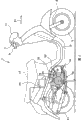
Fig. 1 is the end view of the riding vehicle of example of the present invention.
Fig. 2 is a block diagram of showing the entire system of the Light Control Unit in the example of the present invention.
Fig. 3 is the functional block diagram that constitutes the ECU of the Light Control Unit in the example of the present invention.
Fig. 4 shows that generating stops the flow chart of the function of control part.
Fig. 5 shows that generating stops the flow chart of the function of control part.
Fig. 6 shows that headlamp drives the figure of an example of energy rate (duty) table.
Fig. 7 is a flow chart of showing the function of energy rate control part.
Fig. 8 is the figure that changes the time of generating state, engine speed, headlamp energy rate when showing the acceleration of vehicle.
Label declaration
1 motor bike, 3 front forks
5 front vehicle wheels, 7 handlebars
9 throttle grips, 11 headlamps
13 vehicle body frames, 15 air inlet pipe
17 vehicle seats, 19 blast pipes
21 mufflers, 23 radiators
25 storage batterys, 27 cooling water path
30 engines, 33 generators
35 adjuster 35a rectification circuits
35b switch 35c constant voltage circuit
37 headlamp drive circuits, 51 battery tension transducers
52 vehicle speed sensor, 53 intake manifold pressure sensors
54 crank angle sensors, 70 ECU
71 generatings stop control part 72 energy rate control parts
73 energy rate storage parts, 74 energy rate increment rate configuration parts
75 light quantity increase and decrease portions
Embodiment
Fig. 1 is the end view of the riding vehicle of an example of the present invention.In the figure, aforementioned riding vehicle shows as motor bike.On motor bike 1, be provided with the front fork 3 that extends upward from vehicle front (Fr represent direction) in the figure, bottom.Be provided with front vehicle wheel 5 in the place ahead of motor bike 1, the lower end of front fork 3 is connected with the front axle of front vehicle wheel 5, and rotating freely by front axle, the earth's axis supports front vehicle wheel 5.In the upper end of front fork 3, supporting the handlebar 7 that extends along the overall width direction of vehicle.On an end of handlebar 7 throttle grip 9 is installed, rotates throttle grip 9 by the rider, switch is located at the air throttle that the figure in the air inlet pipe 15 does not show, vehicle just quickens or slows down.Vehicle direct of travel the place ahead at handlebar 7 central portions is equipped with headlamp 11.
Extended vehicle body frame 13 from the central portion of front fork 3 to rear view of vehicle.Specifically, vehicle body frame 13, to rear view of vehicle after tiltedly down direction extends, crooked and flatly extend to rear view of vehicle.Afterwards, vehicle body frame 13, further crooked, extend obliquely upward to rear view of vehicle.Top at vehicle body frame 13 rears disposes vehicle seat 17.
Below vehicle seat 17 front parts, dispose the engine 30 of 4 stroke single-cylinder types, on engine 30, be connected with air inlet pipe 15 and blast pipe 19.And, in engine 30, providing air and fuel from air inlet pipe 15, engine 30 just drives.The waste gas that driving by engine 30 is discharged from expands muffler 21 in by blast pipe 19 backs, and quilt is discharged to vehicle direct of travel rear.At the vehicle direct of travel rear of engine 30 equipped with radiator 23, the cooling water because of the heat temperature of engine 30 rises is sent to this radiator 23 by cooling water path 24, and is cooled at this.
Dispose storage battery 25 below vehicle seat 17 central portions, storage battery 25 is used for providing electric power to headlamp 11 light fixtures such as grade, the various electric components such as spark plug that are provided on the engine 30.In addition, dispose the generator that figure does not show in the end of the bent axle of engine 30, the driving by this generator is with storage battery 25 chargings.Vehicle direct of travel the place ahead at storage battery 25 disposes control unit of engine 70 (ECU), by the various electric components of ECU70 control lift-launch on motor bike 1.Particularly, in this example, by the rider and under the situation that vehicle quickens to the operation of throttle grip 9, the driving of ECU70 generation outage machine 33 (with reference to Fig. 2), the light quantity (luminous quantity) of increase and decrease headlamp 11.
Fig. 2 is the pie graph of the entire system of the Light Control Unit 10 in this example.Generator 33 is via by the adjuster (regulator) 35 of ON/OFF control energising, exporting generation power by ECU70.
Generator 33 as above-mentioned, is installed in an end of the bent axle of engine 30, the output AC voltage by the driving of engine 30.Generator 33 is connected with adjuster 35, thereby this alternating voltage is attached on the adjuster 35.
Adjuster 35 is transformed into the magnitude of voltage of this direct voltage the charging voltage of storage battery 25 after will becoming direct voltage by the ac voltage rectifier that the driving of generator 33 is exported.Specifically, adjuster 35 comprises rectification circuit 35a, switch 35b, constant voltage circuit 35c and constitutes.Rectification circuit 35a comprises a plurality of semiconductor elements such as diode and capacitor and constitutes that the one end is connected on the generator 33, to making its smoothing from generator 33 additional ac voltage rectifiers, is transformed into direct voltage.The other end of rectification circuit 35a is connected with the end of switch 35b, and the other end of switch 35b is connected with storage battery 25 in parallel with headlamp 11.
The end of constant voltage circuit 35c is connected the other end from switch 35b to the pathway of headlamp 11 and storage battery 25.Constant voltage circuit 35c monitoring offers the voltage of the electric power of headlamp 11 and storage battery 25, to switch 35b output and the corresponding switching signal of this voltage, carries out the ON/OFF of switch 35b repeatedly.And, constant voltage circuit 35c, by the pulse duration of opening and closing of modulation switch signal, the magnitude of voltage of the electric power that will provide to storage battery 25 via rectification circuit 35a is transformed into the charging voltage of storage battery 25.Moreover the charging voltage of storage battery 25 is charged to storage battery 25 owing to overcome the output voltage of storage battery 25, therefore will be set to be higher than this output voltage.
ECU70 comprises microcomputer etc. and constitutes that by by this microcomputer executive control program, according to the throttle operation of being made by the rider, control is to the various electric components such as injector of the combustion chamber of engine 30 burner oil.Particularly in this example, ECU70 is by to switch 35b output generating shutoff signal, and 35b is changed to the pass with switch, thus the driving of generation outage machine 33, and stop the charging of the storage battery 25 that undertaken by generator 33.That is, when switch 35b closes, do not flow through electric current on the coil of the stator that constitutes generator 33, the driving of generator 33 is stopped.At this moment, because the output current of generator 33 does not flow, therefore can not produce the power generation loss such as conversion loss of copper loss, adjuster.Then, by the output of ECU70 generation outage shutoff signal, switch 35b is changed to out, and just flows through electric current on the coil of generator 33 once more, and the driving of generator 33 begins once more.Moreover when the driving of generator 33 stopped, headlamp 11 was that electric power source drives with storage battery 25 only just.In addition, as above-mentioned, ECU70 is to headlamp drive circuit 37 output switching signals, and carries out the open/close switching of headlamp drive circuit 37 repeatedly, thereby energy rate drives headlamp 11, makes the light quantity increase and decrease of headlamp 11 thus.
ECU70, be installed in storage battery 25 on detect the output voltage of storage battery battery tension transducer 51 be connected, this detected value is fed to ECU70 as the battery tension signal.In addition, ECU70 is connected on the vehicle speed sensor 52, and vehicle speed sensor 52 will be exported to ECU70 as vehicle speed signal with the corresponding magnitude of voltage of the speed of a motor vehicle.In addition, ECU70 is connected with intake manifold pressure sensor 53 on the inwall that is installed in the air inlet pipe, and intake manifold pressure sensor 53 will be exported to ECU70 as the suction press signal with the corresponding magnitude of voltage of the pressure in the air inlet pipe.
And then ECU70 is connected on the crank angle sensor 54, detects the crank angle according to the crank angle signal from crank angle sensor 54 inputs, according to crank angle of being detected and suction press signal, during the end of the suction stroke of differentiation engine.Specifically, crank angle sensor 54 in 1 circulation of engine, is distinguished accordingly to ECU70 output crank angular signal with a plurality of crank angles.Therefore, just output crank angular signal repeatedly in 1 circulation of engine.And, make in these a plurality of crank angle signal 1, be exported to ECU70 in the moment of the piston arrives lower dead center of engine.According to suction press input suction press, and compare by the incremental data of the suction press that the change and the ECU70 of suction press stored in advance when the obtaining of each crank angle signal for ECU70, when judging the end of suction stroke.Moreover ECU70 calculates engine speed Ne according to the frequency of obtaining of the time per unit of crank angle signal.
Function for ECU70 illustrates according to Fig. 3.Fig. 3 is the functional block diagram that constitutes the ECU70 of Light Control Unit 10 of the present invention.As shown in the drawing, ECU70 comprising that generating stops control part 71 and light quantity increase and decrease portion 75 and constitutes.
Generating stops control part 71, judges whether vehicle is in when quickening, and under being judged to be situation about being in when quickening, to adjuster 35 output generating shutoff signals, the driving of generation outage machine 33 is worked as the charging restraining device of storage battery.Thus, the charging of storage battery 25 is stopped, and the terminal voltage of storage battery 25 descends.Light quantity increase and decrease portion 75 has or not according to the inhibition of the charging of storage battery 25, makes the light quantity increase and decrease of headlamp 11.Specifically, when generator 33 drives, to 37 outputs of headlamp drive circuit only based on engine speed Ne and the switching signal of the energy rate that comes.In addition, under the situation that vehicle is in when quickening and the driving of generator 33 stops, the just switching signal of high energy rate when 37 outputs of headlamp drive circuit drive than generator 33.So, even if stop in the driving of generator 33, the electric power source of headlamp 11 has only under the situation of storage battery 25, also can suppress the reduction to the additional voltage of headlamp 11, thereby alleviates the variation of the light quantity when quickening.
Below, further specifically describe the function of ECU70.
Generating stops control part 71, and according to the moment of suction press demonstration minimum in 1 circulation of engine, i.e. the change of the suction press the during end of suction stroke is when judging the acceleration of vehicle.Then, be judged to be under the situation that vehicle quickening, to adjuster 35 output generating shutoff signals, 35b is changed to the pass with switch, the driving of generation outage machine 33.Thus, when the acceleration of vehicle, do not have electric current to flow through on the coil of generator 33, the driving of generator 33 stops.Therefore, just can reduce load of electrical generation, improve the acceleration performance of vehicle for engine 30.After the driving that has stopped generator 33, generating stops control part 71, time, the variation of the speed of a motor vehicle and the moment of engine speed institute predetermined conditions in the driving of having satisfied output voltage at storage battery, generation outage machine 33, begin the driving of generator 33 once more.
At this, stop the function of control part 71 for generating, according to Fig. 4 and Fig. 5, explanation in further detail.Fig. 4 is to show the flow chart that is stopped the generating shut down procedure of control part 71 execution by generating.In addition, Fig. 5 be illustrated in started in the execution of generating shut down procedure, be stopped in the driving of generator 33 and be used to after ending to make it to begin the generating that the drives flow chart of start program more once more.
Generating stops control part 71, after the driving of engine 30 begins, and the output (S101) of the crank angle signal when waiting for the end of representing suction stroke.The generating that has obtained this crank angle signal stops the suction press P that control part 71 is obtained this moment, as suction press value n1 last time, the value of P is stored in (S102) in the memory.Then, by the driving of engine 30, crankshaft rotating, the crank angle signal (S103) when waiting for the end of exporting the expression suction stroke once more.Then, when obtaining this crank angle signal once more, generating stops the suction press P that control part 71 is obtained this moment, should be worth storage (S104) as this suction press value n2.Then, deducting from n2 under the situation of difference greater than predefined fiducial value Pk of n1, generating stops control part 71 and is judged to be vehicle and is in when quickening (S105), to adjuster 35 output generating shutoff signals, the driving of generation outage machine 33 (S106).At this moment, because the driving of generator 33 is stopped, so headlamp 11 is a drive source with storage battery 25 only.
On the other hand, be less than or equal under the situation of predefined fiducial value Pk, be not judged to be vehicle and be in when quickening (S105) in the difference that deducts n1 from n2.At this moment, cover the value of n1 by the value (suction press P) of n2, n1 is updated, and will be stored in the value deletion (S107) in the n2 simultaneously.Afterwards, return S103, generating stops control part 71, waits for the output (S103) of the crank angle signal of expression suction stroke once more.
Decision method when stopping acceleration that control part 71 carries out by generating, be to have utilized following principle, promptly, because under the situation that vehicle begins to quicken from constant-speed traveling, carry out throttle operation and air throttle is further opened by the rider, more fuel and air are imported in the air inlet pipe 15 during than constant-speed traveling, so the suction press when quickening rises during than constant-speed traveling.Like this, when judging the acceleration of vehicle, just can promptly react, judge the situation when vehicle is in acceleration the vehicle operating of making by the rider.
The generating of having exported the generating shutoff signal stops control part 71, carries out the start program once more that generates electricity.Specifically, as shown in Figure 5, generating stops control part 71, begins to count the elapsed time T that begins from the moment of having exported the generating shutoff signal, detects the vehicle velocity V 1 (S201) in this moment simultaneously.Then, obtain the battery tension E in the moment of having exported the generating shutoff signal, judge then whether this battery tension E cuts off less than generating and stop lower voltage limit Emin (S202) according to the battery tension signal.Then, stop under the situation of lower voltage limit Emin less than the generating cut-out at battery tension E, the output of generation outage shutoff signal begins the driving (S206) of generator 33 once more.Like this, can prevent the situation that the charge capacity of storage battery 25 extremely reduces.
On the other hand, stop under the situation of lower voltage limit Emin more than or equal to the generating cut-out at battery tension E, the T that judgement is counted when beginning is cut off in generating, whether stop the fiducial value Tmax (S203) that control part 71 is stored in advance greater than generating, surpass under the situation of Tmax the output of generation outage shutoff signal (S206) at T.Be less than or equal at T under the situation of Tmax, judge and quicken whether to finish.Specifically, detect vehicle velocity V once more, and judge the value that deducts vehicle velocity V 1 detected when beginning is cut off in generating from vehicle velocity V, whether stop the fiducial value Vmax (S204) that control part 71 is stored in advance greater than generating.Then, the value of the vehicle velocity V 1 when deducting generating cut-out beginning from vehicle velocity V surpasses under the situation of Vmax the output of generation outage shutoff signal (S206).On the other hand, if this value is less than or equal to Vmax, then calculate engine speed Ne (S205) according to the detection frequency of the time per unit of crank angle signal.Under the situation of engine speed Ne, be judged as engine speed and fully risen to enough greater than the engine speed Nemax that stores in advance.At this moment, the output of generation outage shutoff signal, and once more to engine 30 additional power generation loads (S206).On the other hand, be less than or equal at engine speed Ne under the situation of engine speed Nemax, return S202 once more, the judgement of generating electricity and beginning once more with same step.
Turn back to Fig. 3, light quantity increase and decrease portion 75 comprises energy rate control part 72, energy rate storage part 73 and energy rate increment rate configuration part 74 and constitutes.
The energy rate that headlamp 11 is set in energy rate increment rate configuration part 74 is controlled the increment rate of needed energy rate.Specifically, as the candidate value of energy rate increment rate α, store 0 and value d (1〉d〉0) in advance.Whether energy rate increment rate configuration part 74 stops control part 71 output generating shutoff signals from generating every the stipulated time monitoring, and promptly whether vehicle is in when quickening.Then, under the situation when vehicle is in acceleration, will be worth d and set as energy rate increment rate α.On the other hand, under the situation when vehicle is not in acceleration, set as energy rate increment rate α 0.That is, under the situation when vehicle is not in acceleration, in the energy rate control of headlamp 11, do not carry out the increase of energy rate and dispose.
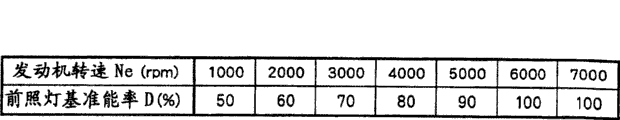
73 storages of energy rate storage part drive the energy counting rate meter with engine speed Ne and the corresponding headlamp of headlamp benchmark energy rate D.Headlamp drives the energy counting rate meter, specifically as shown in Figure 6, is set to the rising along with engine speed Ne, and headlamp benchmark energy rate D also rises.By such setting headlamp benchmark energy rate D, under the situation of low vehicle speeds, reduce headlamp benchmark energy rate D, reduce the electric power offer headlamp 11, thus the electric power consumption when suppressing low speed.On the contrary, at engine speed Ne height, under the situation of high vehicle speeds, increase the electric power that offers headlamp 11, thereby increase the light quantity of headlamp 11.Moreover it can counting rate meter be an example that headlamp shown in Figure 6 drives, also can be with the further sectionalization of engine speed Ne, store headlamp benchmark energy rate D accordingly with the engine speed Ne of this sectionalization.In addition, also can calculate headlamp benchmark energy rate D from the engine speed Ne that is given with the calculation formula of regulation.
Energy rate control part 72, when the constant-speed traveling of vehicle to the switching signal of the energy rate of headlamp drive circuit 37 input less thaies 1, when the acceleration of vehicle, to the switching signal of headlamp drive circuit 37 inputs high energy rate during than constant-speed traveling.Thus, even if the charging of storage battery 25 stops when quickening, the light quantity of headlamp 11 also is difficult to change.
Promptly, the output of the crank angle signal when energy rate control part 72 is monitored the end of representing suction strokes, when the output of this crank angle signal, energy rate increment rate α according to the headlamp that is stored in the energy rate storage part 73 drives the energy counting rate meter and set by energy rate increment rate configuration part 74 calculates the headlamp energy rate Df to the switching signal of headlamp drive circuit 37 outputs.Then, the switching signal of this headlamp energy rate Df is exported to headlamp drive circuit 37.Like this, whether energy rate control part 72 drives according to engine speed Ne and generator 33, by each engine cycles, the energy rate when the decision energy rate drives headlamp 11, the variation of the light quantity of the headlamp 11 that produces when the driving that suppresses generator 33 stops or when driving beginning.
At this, the function for energy rate control part 72 further specifically describes.Fig. 7 is a flow chart of showing the processing of energy rate control part 72, and this processing repeats in each engine cycles.Energy rate control part 72, the arrival (S301) of the crank angle signal when monitoring the end of representing suction stroke.Then, when the crank angle signal when the end of expression suction stroke is output, calculate engine speed Ne (S302).Engine speed Ne also can calculate according to the detection frequency of the crank angle signal of the regulation of time per unit, can also according to the detection of the crank angle signal of the different crank angle of expression regularly the difference of ( イ ミ Application グ) calculate.Afterwards, energy rate control part 72 reads in the energy rate increment rate α (S303) that is set by energy rate increment rate configuration part 74.And, drive and to read in and the corresponding headlamp benchmark of engine speed Ne energy rate D (S304) by counting rate meter from headlamp, calculate the value that headlamp benchmark energy rate D multiply by energy rate increment rate α then, and calculate the headlamp energy rate Df that on this value, adds headlamp benchmark energy rate D (Df=D+ α * D), and the switching signal of this headlamp energy rate Df exported to headlamp drive circuit 37 (S305).
At this moment, when vehicle is not in acceleration, and under the situation that generator 33 is driving, owing to set as energy rate increment rate α 0 in energy rate increment rate configuration part 74, so headlamp energy rate Df is and is stored in headlamp and drives the value that the headlamp benchmark energy rate D in can counting rate meter equates.On the other hand, be in when quickening at vehicle, and generator 33 not have under the situation of driving, headlamp energy rate Df becomes the energy rate that exceeds value d * D than headlamp benchmark energy rate D.Its result, the switching signal of the energy rate higher than headlamp benchmark energy rate D is exported to headlamp drive circuit 37, thus the minimizing of the light quantity of the headlamp 11 when quickening is suppressed.
As described above such, according to this example, even if vehicle is in accelerator, and the driving of generator 33 stops, headlamp 11 is a drive source with storage battery 25 only, by making the energy rate that is attached to the voltage on the headlamp 11, increase the regulation ratio from energy rate by engine speed Ne decision, just can suppress the variation of its light quantity.In addition, when the driving of generator 33 begins once more, cancel the increase of the energy rate of aforementioned regulation ratio, as original, drive headlamp 11, therefore can suppress the variation of the light quantity of headlamp 11 by energy rate by engine speed Ne decision.
Fig. 8 is the chart of expression by the time variation of this example generating state, engine speed Ne and headlamp energy rate Df that realize, generator 33.In the figure, transverse axis is all represented the elapsed time, and the longitudinal axis of Fig. 8 (a) is represented generating state, and the longitudinal axis of Fig. 8 (b) is represented engine speed, and the longitudinal axis of Fig. 8 (c) is represented headlamp energy rate Df.
Expression is in this figure (a), is in moment t1 when quickening being judged as vehicle, and the generating state of generator 33 becomes the driving halted state from driving condition.In this figure (b), become the moment t1 that drives halted state from the generating state of generator 33 from driving condition, engine speed Ne rises.Why like this moreover in this figure (b), rising and descending appears in engine speed Ne one side repeatedly, and one side rises gradually along with effluxion,, be because the cause that engine speed Ne changes in 1 circulation of engine.In this figure (c), be illustrated in generating state and become the moment t1 that drives halted state, the risen situation of amount of value d * D of headlamp energy rate Df from driving condition.And, after having expressed along with the rising of engine speed Ne, situation that headlamp energy rate Df rises gradually.
Moreover, the invention is not restricted to above-mentioned example, can carry out various distortion.For example, in the above description, by additional voltage to headlamp 11 is carried out energy rate control, when the acceleration of vehicle, increase the disposal of energy rate, thereby suppressed the variation of the light quantity of headlamp 11, but the method for the variation of the light quantity of inhibition headlamp 11 is not limited thereto.For example, utilize resistor that the output voltage of storage battery 25 is reduced, the voltage after reducing is attached on the headlamp 11, and can closes the voltage of realizing by resistor with switch opens and reduce, light quantity is changed by constituting.Like this, by when the charging of storage battery 25, to realize that the battery tension after voltage reduces is attached on the headlamp 11 by resistor, when the charging of storage battery 25 suppresses, the battery tension that will reduce less than the voltage that acquisition is realized by resistor is attached on the headlamp 11, thereby can suppress the variation of the light quantity of headlamp 11.
In addition, by constituting headlamp 11, also can suppress the variation of light quantity by the different separately a plurality of luminous elements of light quantity (for example filament etc.).That is, under the situation of storage battery 25 chargings, be made as the luminous element energising less to light quantity.And under the repressed situation of the charging of storage battery 25, be made as the luminous element energising bigger to light quantity.The variation of the light quantity that produces in the time of thus, can being suppressed at the driving of generator 33, between driving when stopping.
Claims (4)
1. the Light Control Unit of a riding vehicle is characterized in that, possesses:
By engine-driven generator;
Storage battery by aforementioned generator charging;
The charging restraining device of the charging of the aforementioned storage battery that inhibition is undertaken by aforementioned generator;
Be connected the light fixture on the aforementioned storage battery; With
Along with the inhibition of the driving of the aforementioned generator that is undertaken by aforementioned charging restraining device, increase and decrease the light quantity increase and decrease device of the light quantity of aforementioned light fixture;
Aforementioned light quantity increase and decrease device when energy rate is controlled aforementioned light fixture, is in when quickening and the driving of above-mentioned generator when stopping at vehicle, and the energy rate that makes described energy rate control aforementioned light fixture increases.
2. the Light Control Unit of riding vehicle as claimed in claim 1 is characterized in that, decision maker during acceleration when further comprising the acceleration of judging aforementioned riding vehicle;
Aforementioned charging restraining device, decision maker is judged to be under the situation that aforementioned riding vehicle quickening by aforementioned quicken the time, suppresses the driving of aforementioned generator, suppresses the charging of aforementioned storage battery thus.
3. the Light Control Unit of riding vehicle as claimed in claim 1 is characterized in that, aforementioned light quantity increases and decreases device, further increases and decreases the light quantity of aforementioned light fixture along with the rotating speed of aforementioned engine.
4. riding vehicle, this riding vehicle possesses any described Light Control Unit in the claim 1 to 3.
Applications Claiming Priority (2)
| Application Number | Priority Date | Filing Date | Title |
|---|---|---|---|
| JP100247/2005 | 2005-03-30 | ||
| JP2005100247A JP2006273298A (en) | 2005-03-30 | 2005-03-30 | Lighting control device and straddle type vehicle provided with lighting control device |
Publications (2)
| Publication Number | Publication Date |
|---|---|
| CN1841881A CN1841881A (en) | 2006-10-04 |
| CN100492806C true CN100492806C (en) | 2009-05-27 |
Family
ID=37030765
Family Applications (1)
| Application Number | Title | Priority Date | Filing Date |
|---|---|---|---|
| CNB2006100572063A Expired - Fee Related CN100492806C (en) | 2005-03-30 | 2006-03-07 | Light control device and saddle type vehicle equipped with light controller |
Country Status (3)
| Country | Link |
|---|---|
| JP (1) | JP2006273298A (en) |
| CN (1) | CN100492806C (en) |
| TW (1) | TW200633895A (en) |
Families Citing this family (4)
| Publication number | Priority date | Publication date | Assignee | Title |
|---|---|---|---|---|
| JP5474362B2 (en) * | 2009-02-03 | 2014-04-16 | 朝日電装株式会社 | Turn signal switch device |
| JP2015214227A (en) * | 2014-05-09 | 2015-12-03 | ヤマハ発動機株式会社 | Saddle-riding type vehicle |
| JP6980641B2 (en) * | 2018-12-25 | 2021-12-15 | 本田技研工業株式会社 | Saddle-type vehicle |
| WO2023127075A1 (en) * | 2021-12-28 | 2023-07-06 | 本田技研工業株式会社 | Saddled vehicle |
Citations (1)
| Publication number | Priority date | Publication date | Assignee | Title |
|---|---|---|---|---|
| US4689545A (en) * | 1985-03-04 | 1987-08-25 | Mitsubishi Denki Kabushiki Kaisha | Control apparatus for vehicle battery charging generator |
-
2005
- 2005-03-30 JP JP2005100247A patent/JP2006273298A/en active Pending
-
2006
- 2006-01-24 TW TW095102648A patent/TW200633895A/en not_active IP Right Cessation
- 2006-03-07 CN CNB2006100572063A patent/CN100492806C/en not_active Expired - Fee Related
Patent Citations (1)
| Publication number | Priority date | Publication date | Assignee | Title |
|---|---|---|---|---|
| US4689545A (en) * | 1985-03-04 | 1987-08-25 | Mitsubishi Denki Kabushiki Kaisha | Control apparatus for vehicle battery charging generator |
Also Published As
| Publication number | Publication date |
|---|---|
| TWI295980B (en) | 2008-04-21 |
| TW200633895A (en) | 2006-10-01 |
| CN1841881A (en) | 2006-10-04 |
| JP2006273298A (en) | 2006-10-12 |
Similar Documents
| Publication | Publication Date | Title |
|---|---|---|
| CN100404319C (en) | The wiring harness structure of electric motorcycle | |
| US6260644B1 (en) | Motor controlling apparatus for a hybrid car | |
| CN101421499B (en) | Variable valve-actuating device, control method for the device, and vehicle carrying the device | |
| US7527111B2 (en) | Driving device for hybrid vehicle, and hybrid vehicle incorporating the same | |
| US8096376B2 (en) | Hybrid vehicle | |
| CN108688647A (en) | The control method of automobile, the control device of automobile and automobile | |
| CN1788153B (en) | Fuel pump control device and fuel pump control method | |
| CN100492806C (en) | Light control device and saddle type vehicle equipped with light controller | |
| CN101340109B (en) | Power generation control device and vehicle having the same | |
| CN1815846B (en) | Apparatus and method of controlling generator, and motorcycle | |
| US20090143930A1 (en) | Hybrid electric vehicle | |
| JP4752919B2 (en) | Engine control device | |
| JP3746900B2 (en) | Control device for hybrid vehicle | |
| CN103118917B (en) | The output-controlling device of explosive motor | |
| JP4191149B2 (en) | Hybrid vehicle driving force control device | |
| CN101639018B (en) | Power supply controller | |
| JP4770468B2 (en) | Control device for vehicle generator | |
| JP5012748B2 (en) | Control device for hybrid vehicle | |
| EP0779419A2 (en) | Improvements made in the engine assembly of automotive vehicles | |
| KR102183178B1 (en) | Vehicle and control method of vehicle | |
| CN111868359B (en) | Motor bicycle | |
| EP3589834A1 (en) | A starter system for a vehicle | |
| JP2020012458A (en) | Control device | |
| JP2013113258A (en) | Internal-combustion engine control device | |
| JP2006046297A (en) | Controller for hybrid vehicle |
Legal Events
| Date | Code | Title | Description |
|---|---|---|---|
| C06 | Publication | ||
| PB01 | Publication | ||
| C10 | Entry into substantive examination | ||
| SE01 | Entry into force of request for substantive examination | ||
| C14 | Grant of patent or utility model | ||
| GR01 | Patent grant | ||
| CF01 | Termination of patent right due to non-payment of annual fee | ||
| CF01 | Termination of patent right due to non-payment of annual fee |
Granted publication date: 20090527 Termination date: 20180307 |