CN100475103C - Multipower heating device - Google Patents
Multipower heating device Download PDFInfo
- Publication number
- CN100475103C CN100475103C CNB021515654A CN02151565A CN100475103C CN 100475103 C CN100475103 C CN 100475103C CN B021515654 A CNB021515654 A CN B021515654A CN 02151565 A CN02151565 A CN 02151565A CN 100475103 C CN100475103 C CN 100475103C
- Authority
- CN
- China
- Prior art keywords
- heater
- heating element
- heaters
- heating
- seat
- Prior art date
- Legal status (The legal status is an assumption and is not a legal conclusion. Google has not performed a legal analysis and makes no representation as to the accuracy of the status listed.)
- Expired - Fee Related
Links
Images


Classifications
-
- H—ELECTRICITY
- H05—ELECTRIC TECHNIQUES NOT OTHERWISE PROVIDED FOR
- H05B—ELECTRIC HEATING; ELECTRIC LIGHT SOURCES NOT OTHERWISE PROVIDED FOR; CIRCUIT ARRANGEMENTS FOR ELECTRIC LIGHT SOURCES, IN GENERAL
- H05B3/00—Ohmic-resistance heating
- H05B3/78—Heating arrangements specially adapted for immersion heating
- H05B3/82—Fixedly-mounted immersion heaters
-
- A—HUMAN NECESSITIES
- A47—FURNITURE; DOMESTIC ARTICLES OR APPLIANCES; COFFEE MILLS; SPICE MILLS; SUCTION CLEANERS IN GENERAL
- A47J—KITCHEN EQUIPMENT; COFFEE MILLS; SPICE MILLS; APPARATUS FOR MAKING BEVERAGES
- A47J27/00—Cooking-vessels
- A47J27/21—Water-boiling vessels, e.g. kettles
- A47J27/21008—Water-boiling vessels, e.g. kettles electrically heated
- A47J27/21041—Water-boiling vessels, e.g. kettles electrically heated with heating elements arranged outside the water vessel
-
- A—HUMAN NECESSITIES
- A47—FURNITURE; DOMESTIC ARTICLES OR APPLIANCES; COFFEE MILLS; SPICE MILLS; SUCTION CLEANERS IN GENERAL
- A47J—KITCHEN EQUIPMENT; COFFEE MILLS; SPICE MILLS; APPARATUS FOR MAKING BEVERAGES
- A47J27/00—Cooking-vessels
- A47J27/21—Water-boiling vessels, e.g. kettles
- A47J27/21008—Water-boiling vessels, e.g. kettles electrically heated
- A47J27/21058—Control devices to avoid overheating, i.e. "dry" boiling, or to detect boiling of the water
- A47J27/21083—Control devices to avoid overheating, i.e. "dry" boiling, or to detect boiling of the water with variable operating parameters, e.g. temperature or boiling period
-
- A—HUMAN NECESSITIES
- A47—FURNITURE; DOMESTIC ARTICLES OR APPLIANCES; COFFEE MILLS; SPICE MILLS; SUCTION CLEANERS IN GENERAL
- A47J—KITCHEN EQUIPMENT; COFFEE MILLS; SPICE MILLS; APPARATUS FOR MAKING BEVERAGES
- A47J27/00—Cooking-vessels
- A47J27/21—Water-boiling vessels, e.g. kettles
- A47J27/21166—Constructional details or accessories
-
- H—ELECTRICITY
- H05—ELECTRIC TECHNIQUES NOT OTHERWISE PROVIDED FOR
- H05B—ELECTRIC HEATING; ELECTRIC LIGHT SOURCES NOT OTHERWISE PROVIDED FOR; CIRCUIT ARRANGEMENTS FOR ELECTRIC LIGHT SOURCES, IN GENERAL
- H05B2203/00—Aspects relating to Ohmic resistive heating covered by group H05B3/00
- H05B2203/021—Heaters specially adapted for heating liquids
Abstract
A heater base assembly for a liquid heating vessel comprises a base member, a first sheathed high powered heating element in close thermal contact with said base member and a second lower power sheathed heating element disposed substantially beneath or horizontally adjacent to said first heating element.
Description
Technical field
The present invention relates to a kind of electric heater of heating vessel,, but be not limited in this especially for boiling water container.
Background technology
The difference application of the electric heater of many relevant heating vessels is arranged in recent years.The heater of some application can not only worked under a power, can obtain being lower than the ideal temperature that seethes with excitement and be used to make coffee, or continuation is slowly to boil water with slow fire after boiling, such as giving contaminated water sterilization.
But still need a kind of effective and economic heater that can under different power levels, work.
Summary of the invention
From a first aspect of the present invention, the heater pedestal assembly of heating vessel provided by the invention comprises a seat element, first heating element heater with clad, contact with described seat element close thermal, second heating element heater with clad is installed in the below of described first heating element heater substantially.
Therefore can find out that according to heater of the present invention two heating element heaters with clad can be arranged, one below another.So just can give the energising of one of two elements selectively, or all switch on, thereby can use two different heating powers to the two.By an element being placed the upper end of another element, can make the overall diameter minimum of heater.
First heating element heater contact with close thermal between seat element by one efficiently heat-conduction medium realize, distribute metallic plate as heat commonly used.Selectively, or additionally first heating element heater preferably directly weldering (bond) or be contained on the seat element.Heat just can directly pass to seat element like this, therefore just can pass to heating liquid in use, and need not distribute metallic plate with heat.
In some most preferred embodiments, directly two heating element heaters are stacked together mutually.Below heating element heater (promptly when the heating element heater below heater is in first heating element heater during in normal operating conditions) heat is passed to seat element, pass to water or other heating liquid then, pass through first heating element heater indirectly.But second heating element heater preferably also contacts with the seat element close thermal.Preferably contact the close thermal contact that realizes between heating element heater and the seat element by close physical.
Preferably, heater comprises a heat-conduction component, and it contacts with a part of close thermal of described second heating element heater, and also is arranged to the seat element close thermal and contacts, as described in patent EP-A-1215939A.In this best assembling, heat-conduction component is clipped between first and second heating element heaters.Heat just can any passes to heat-conduction component from two heating element heaters rapidly and effectively like this.
In another preferred embodiment, two heating element heaters are located between seat element and the heat-conduction component.First heating element heater is directly passed to seat element with heat, closely contact with it such as passing through, yet second heating element heater is mainly passed to seat element by heat-conduction component with heat.
It is the plane that the heating part of seat element can resemble the underfloor heating system of knowing.But in some preferred embodiments, seat element comprises the circumferential step part, and it can hold described first heating element heater.This can effectively improve the contact area between heating element heater and the seat element.Its bottom can also reduce the diameter of seat element in some cases, because need not hold heating element heater and control module again.
When with two disposition of heating component between seat element and heat-conduction component and in conjunction with above-mentioned feature the time, can obtain the most preferred embodiment of a uniqueness, promptly two heating element heaters are installed in the step of seat element, heat-conduction component be mounted to the part of second heating element heater up and down overlapping and close thermal contact, also contact with a part of close thermal of seat element.Preferably, described first and second heating element heaters directly are welded on the seat element.
To be objective, this device has its special advantage, when from another point of view, the heating base of heating vessel of the present invention, comprise seat element, directly be welded in and be used for first heating element heater with clad of liquid in the heating container on the seat element, be mounted to and be located at described first heating element heater below and directly be welded in second heating element heater on the described seat element with clad, described first and second heating element heaters are installed in the step of seat element, one heat-conduction component be mounted to the part of second heating element heater with clad up and down overlapping and close thermal contact, and contact with a part of close thermal of container base element.
In another aspect of this invention, two heating element heaters can adopt identical rated power, can obtain lower power by giving the energising of one of element, and the two is switched on simultaneously obtains higher power, to obtain different heating effects.
Preferably, the power difference of two heating element heaters.Preferably one of them heating element heater has enough power with water boil, and its power preferably between near 1.5 to 3kw, is preferably between 2 to 3kw.But the power slow fire of another low-power heating element heater is to boil water, or water temperature is controlled at boils followingly, but is not enough to cold water is boiled.Described low-power heating element heater preferably at 10 watts (w) between 1 kilowtt (kw), at 50w to best between 800w.
Under the situation of the heating element heater with two different capacities, preferably high-power heating element contacts with the seat element close thermal at least, and the power that promptly preferably has first heating element heater of clad is higher than second heating element heater.
Although be not main points of the present invention, in actual applications, said here heating base can combine with the heat control device of some forms.This control device is just for one or two heating element heater provides power-off protection, in case it or they overheated, heater is still switched on when for example causing not having water in the container, or container is boiled dry.If the water that second slow fire heating element heater is used for having been boiled by first heating element heater in the container remains on boiling or during near boiling, the situation than common is big certainly for a kind of possibility in back, because this type of device is not used for controlling the steam cock of slow fire element usually.
But preferably allow control device in the routine work process, optionally give one or two heating element heater energising.For example, the design of control device is all switched on two heating element heaters beginning, so that water boil, cuts off the power supply of main (high-power) heating element heater afterwards, only keeps slow fire heating element heater or the energising of insulation heating element heater.Available suitable thermal response sensor such as the bimetallic starter of jerking, thus main heating element heater is cut off in the existence of surveying steam, or survey whether meet the requirements of water temperature.In most preferred embodiment, available storage tank is so that boiling water is surveyed, and this has explanation in patent WO02/085169.
Be ease of assembly and coordination reliability, can adopt as applicant's the U17 and the whole control module of U18 controller series the control configuration is provided.In another possible selection, can adopt a pair ofly from holding bimetallic starter and switch module, for example have suitable interconnected so-called " half inch disk ".Its advantage is that hardware investment is low, can make the device compactness again.Can be used to survey predetermined temperature such as the module in location, disconnect main heating element heater then, locate second module safe disconnection can be provided under the situation of overheated heater.
The present invention is not limited to two heating element heaters, and three even more a plurality of heating element heater can be arranged.It is contemplated that the heater of the 3rd heating element heater, but recommend also with heating element heater with clad with the thick film form.The 3rd heating element heater with clad can separate with first and second heating element heaters, but preferably is soldered in them one.For instance, three heating units can be heated to boiling to water, keep water temperature simmers with slow fire at boiling point or below the boiling point, and water temperature can be controlled at a relatively low temperature.Can make operation very flexible optionally for these element energisings.
Above introduce a heating element heater that many kinds will have clad and placed difference configuration under another heating element heater.The applicant recognized at least therein some configurations, by with the mutual level of two heating element heaters near and non-perpendicular near obtaining similar advantage.
Therefore, comprise a seat element, a pair of heating element heater that is contained on the seat element from the electric heater of angle heating vessel of the present invention widely with clad, described heating element heater with clad is welded together mutually, and be installed on the described seat element, thereby be located substantially in the same plane.
Two heating element heaters all can be installed in standard heat and distribute on metallic plate or other heat-conduction medium, be welded on the seat element.Simultaneously, one or two heating element heater can directly be welded on the seat element.For this configuration, heat-conduction component can be mounted to overlapping up and down with the part of at least one or two described heating element heaters and with it close thermal contact, also can contact, described in patent EP1215939A with the portion of hot of seat element.
In another preferred embodiment, two heating element heaters are contained in the circumferential step part of seat element, thereby basic concordant with its central part.This helps to reduce the total height of heating base.
According to various aspects of the present invention, the heating element heater with clad can adopt any size easily and shape.For example, they may extend to whole base component, local disc, or even more than whole disc.The cross section of described heating element heater can be any shape easily, and such as circular, avette, triangle, their shape can be different.But the heating element heater of two clads preferably is rectangle substantially, and is square better.Can make between the heating element heater like this, the contact area maximum between heating element heater and seat element and the heat-conduction component etc.
Various aspects according to the invention described above and most preferred embodiment thereof, can find out that seat element is preferably in the groove that its periphery has upward opening, so that fixing reliably and seal fluid heating container, can be with reference to the patent WO96/18331 of applicant's relevant secure fixation sealing system.
Description of drawings
With reference to the accompanying drawings, by case description preferred forms of the present invention.
Fig. 1 is according to the heating base of first embodiment of the invention and the cutaway view of control module;
Fig. 2 a is the perspective view that the present invention has second embodiment of three heating element heaters;
Fig. 2 b is the cutaway view of Fig. 2 a along the A-A line;
Fig. 3 is the partial sectional view of the 3rd embodiment;
Fig. 4 is the partial sectional view of the 4th embodiment;
Fig. 5 a is the cutaway view of the 5th embodiment;
Fig. 5 b is the cutaway view of Fig. 5 a along the B-B line;
Fig. 6 is the partial sectional view of the 6th embodiment;
Fig. 7 is the cutaway view of the 7th embodiment.
The specific embodiment
At first find out electrical heating pedestal on the heating vessel with reference to Fig. 1.Stainless steel seat element 2 has circumferential step 4.Two heating element heaters 6 and 8 with clad are arranged in the step 4, and they are solded into step 4 and welded together mutually.So two heating element heaters 6 all are that close thermal contacts with 8 with seat element 2.Top element 6 power are higher, are the main members of boiling water in the heating container.For example its power can reach 2.5kw.Following element 8 is that a low-power simmers element, and power can be 350w, the state that it can make the water maintenance in the container slowly boil with slow fire.
As described in patent EP1215939A, heat distribution member 10 is welded on pedestal 2 belows, extends and is welded on the lower element 8.Heat distribution member is made by heat conductivity high material such as metal, comprises copper, aluminium and alloy thereof.
Below heat distribution member 10 control module 12, its suitable applicant's standard U18, so steam chopper switch 14 can only cut off the power supply by last element 6, and the element 8 of bottom still is in conducting.In other words, be exactly the steam cock contact of an electrode Parallel Control of power supply unit 12 of the element 8 of bottom, make it to be in "on" position.If but the design of control module 12 makes that heater is the dry type tripping operation, the bimetallic of arbitrary dry type switch all will disconnect tripping operation, therefore cut off the power supply of element 6 and 8 by another electrode.
In the process of using, the common power output when element 6 and 8 is all switched at the beginning is 2.85kw.After the water in the container is boiled, steam chopper switch 14 will cut off the power supply of major component 6, only stay the 350w warm keeping element and be in "on" position, and the water in the container is simmered with slow fire.This water that will continue up in the container dryouies, and wherein a dry type adds the power supply that the thermo bimetal will disconnect two elements 6 and 8, cools down once more up to heater.
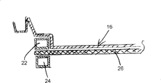
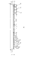
Referring now to Fig. 2 a and 2b,, can see the heating base among second embodiment.This pedestal comprises a stainless steel seat element 16, along its top edge circumferential grooves 18 is arranged, and is used for base is fixed and is sealed on the heating vessel, and this has more detailed description in patent WO9618331.
As embodiment one, a step 20 is also arranged on its seat element 16, but its degree of depth can only be held the heating element heater 22 that the next one has clad.Second heating element heater 24 with clad distributes metallic plate 26 to separate with first heating element heater by extending in seat element 16 following heat below first heating element heater 22.The 3rd heating element heater 28 and second heating element heater, 24 levels next-door neighbour with clad with clad, and welded together, make them mutually in one plane.
It should be noted that first heating element heater 22 and liquid in the container have thermo-contact the most closely, because it has two sides and seat element 16 directly welded together.The 3rd heating element heater 28 is less with the thermo-contact of seat element 16, because they are distributed the thickness of metallic plate 26 to separate by heat.The thermo-contact of second heating element heater 24 and seat element 16 still less because the seat element 16 main hot paths that add belong to plate 26 from side direction through overheated allotment money.Described in patent EP-A-1215939A, its efficient is lower.Cold afterbody 24a and 28a at the second and the 3rd heating element heater one end connect together through shared contact 30, thus can a shared power electrode contact.
In this embodiment, first heating element heater 22 is main thermals source, and its power can reach 1850w.Second heating element heater, 24 power are 300w, and the power of the 3rd heating element heater is 50w.Element 22,24 and 28 is all switched on, and accessible general power is 2.2kw, water can be boiled very soon.In case water is boiled, main heating element heater will be cut off, and the power that stays 350w can be kept slow fire effectively and simmer.When only allowing the 3rd heating element heater 28 switch on, water will maintain a lower equilibrium temperature, and such as 85 ℃, this is the ideal temperature of making coffee.
Fig. 3 illustrates the part of third embodiment of the invention.This embodiment is identical with the embodiment shown in Fig. 2 a and the 2b, has just saved the 3rd heating element heater, so need not be further elaborated again.
Fig. 4 illustrates the part of fourth embodiment of the invention.First heating element heater 32 that has clad in this embodiment is welded in heat and distributes on the metallic plate 34, heat distribute metallic plate 34 be welded in again stainless steel seat element 36 below, this is common situation.But second heating element heater 38 with clad be welded in first element 32 below.The power of second heating element heater 38 may be lower than main heating element heater 32.All these, adding its shell by first heating element heater 3 is that indirect thermal is connected with seat element, just means that it can only be used for water is maintained under the boiling temperature.
Fig. 5 a and 5b are respectively plane and the cutaway views of the 5th embodiment.In this embodiment, two heating element heaters 40 and 42 with clad are adjacent to welded together on heat distribution metallic plate 44.Radially outer element 40 power are lower, belong to the insulation heating element heater, are main heating element heater yet lean on the element 42 of lining.Cold afterbody 40a and 42a are connected together by shared connector 46.
Fig. 6 illustrates the part of the 6th embodiment.This embodiment and Fig. 5 a and 5b illustrated embodiment are approximate, and just its two heating element heater 48 and 50 distributes metallic plate 54 to be fixed on the seat element 52 by heat, directly two elements is welded in the step 56 of suitable shape on the seat element 52.Heat distributes metallic plate 54 to be welded in the downside of element 48 and 50, also be welded in seat element 52 below.Step 56 makes the element 48 can be concordant below seat element 52 with 50.
At last, Fig. 7 illustrates the 7th embodiment.This embodiment is similar with the 5b illustrated embodiment to Fig. 5 a, and just it has the 3rd heating element heater 62 with clad.Identical with the embodiment shown in Fig. 2 a and the 2b, three heating element heaters 58,60 and 62 power can be respectively 1850w, 300w and 50w, and the working method of heater is identical like this.
It will be understood by those skilled in the art that within the scope of the invention and can make various deformation description embodiment.For example, all have heat to distribute metallic plate among many embodiment, but the disclosed heat-conduction component of its available patent EP-A-1215939A replace.Be also to be understood that according to specific purposes and may change relative power with heating element heater.
Claims (24)
1. the heater of a heating vessel, comprise a seat element and first heating element heater that contacts with described seat element close thermal with clad, it is characterized in that, this heater also comprises: have second heating element heater of clad, be positioned at described below with first heating element heater of clad substantially; And a heat-conduction component, this heat-conduction component is arranged to contact with a part of close thermal of one of described at least first and second heating element heaters and contact with described seat element close thermal.
2. heater as claimed in claim 1 is characterized in that: described first heating element heater is directly to be welded in or to be fixed on the seat element.
3. heater as claimed in claim 1 or 2 is characterized in that: described first heating element heater directly is stacked in the upper end of described second heating element heater.
4. heater as claimed in claim 3 is characterized in that: described second heating element heater contacts with the seat element close thermal.
5. heater as claimed in claim 4 is characterized in that: described second heating element heater directly is welded in or is fixed on the seat element.
6. heater as claimed in claim 1 or 2 is characterized in that: described heat-conduction component contacts with a part of close thermal of described second heating element heater.
7. heater as claimed in claim 6 is characterized in that: described heat-conduction component is clipped between first and second heating element heaters.
8. heater as claimed in claim 6 is characterized in that: described two heating element heaters are between seat element and heat-conduction component.
9. heater as claimed in claim 1 or 2 is characterized in that: described seat element comprises a circumferential step part, and it can hold described first heating element heater.
10. heater as claimed in claim 1 is characterized in that: described first and second heating element heaters are installed in the step of seat element, and described heat-conduction component be installed into the part of second heating element heater up and down overlapping and close thermal contact.
11. heater as claimed in claim 10 is characterized in that: described first and second heating element heaters directly are welded on the seat element.
12. the heater of a heating vessel comprises: a seat element; First electrical heating elements with clad, directly be welded on the seat element liquid in the heating container, it is characterized in that: this heater also comprises second heating element heater with clad, be mounted to the below that is located at described first heating element heater, and directly be welded on the described seat element, described first and second heating element heaters are installed in the step of seat element, one heat-conduction component be arranged to the part of second heating element heater with clad up and down overlapping and close thermal contact, and contact with a part of close thermal of the seat element of container.
13., it is characterized in that: the described first and second heater element power differences as claim 1 or 2 or 12 described heaters.
14. heater as claimed in claim 13 is characterized in that: one of described heating element heater has enough big power can be with water boil.
15. heater as claimed in claim 14 is characterized in that: the power of another heating element heater is can slow fire slowly to boil water, or water temperature is remained under the boiling, but is not enough to cold water is boiled.
16. heater as claimed in claim 13 is characterized in that: high-power heating element contacts with the seat element close thermal at least.
17., it is characterized in that: comprise a control device, so that in the process of operate as normal, connect one or two heating element heater selectively as claim 1 or 2 or 12 described heaters.
18. heater as claimed in claim 17 is characterized in that: comprise a control module intactly.
19. heater as claimed in claim 17 is characterized in that: comprise a pair of starter of bimetallic independently and switch module.
20., it is characterized in that: except described first heating element heater and second heating element heater, also comprise one the 3rd heating element heater and a plurality of heating element heater as claim 1 or 2 or 12 described heaters.
21. heater as claimed in claim 20 is characterized in that: described the 3rd heating element heater comprises a heating element heater with clad that is welded on one of described first and second heating element heaters.
22. as claim 1 or 2 or 12 described heaters, it is characterized in that: described first and second heating element heaters have shell, its shape is rectangle substantially.
23. heater as claimed in claim 22 is characterized in that: described first and second heating element heaters have shell, and its shape is square substantially.
24. as claim 1 or 2 or 12 described heaters, it is characterized in that: described seat element comprises the groove around its peripheral upward opening.
Applications Claiming Priority (2)
| Application Number | Priority Date | Filing Date | Title |
|---|---|---|---|
| EP01310162A EP1215939B2 (en) | 2000-12-06 | 2001-12-05 | Liquid heating vessels |
| EP01310162.1 | 2001-12-05 |
Related Child Applications (1)
| Application Number | Title | Priority Date | Filing Date |
|---|---|---|---|
| CNB2005101203269A Division CN100480595C (en) | 2001-12-05 | 2002-12-05 | Heating base for liquid heating container |
Publications (2)
| Publication Number | Publication Date |
|---|---|
| CN1436505A CN1436505A (en) | 2003-08-20 |
| CN100475103C true CN100475103C (en) | 2009-04-08 |
Family
ID=8182515
Family Applications (3)
| Application Number | Title | Priority Date | Filing Date |
|---|---|---|---|
| CNB021515654A Expired - Fee Related CN100475103C (en) | 2001-12-05 | 2002-12-05 | Multipower heating device |
| CNB2005101203269A Expired - Fee Related CN100480595C (en) | 2001-12-05 | 2002-12-05 | Heating base for liquid heating container |
| CN02292861U Expired - Lifetime CN2594719Y (en) | 2001-12-05 | 2002-12-05 | Multiple power heater |
Family Applications After (2)
| Application Number | Title | Priority Date | Filing Date |
|---|---|---|---|
| CNB2005101203269A Expired - Fee Related CN100480595C (en) | 2001-12-05 | 2002-12-05 | Heating base for liquid heating container |
| CN02292861U Expired - Lifetime CN2594719Y (en) | 2001-12-05 | 2002-12-05 | Multiple power heater |
Country Status (3)
| Country | Link |
|---|---|
| CN (3) | CN100475103C (en) |
| DE (1) | DE20218792U1 (en) |
| GB (1) | GB2393372B (en) |
Families Citing this family (12)
| Publication number | Priority date | Publication date | Assignee | Title |
|---|---|---|---|---|
| GB2414162B (en) * | 2002-02-26 | 2006-05-03 | Strix Ltd | Electric liquid heating appliances |
| FR2876535B1 (en) * | 2004-10-13 | 2006-12-01 | Seb Sa | HEATING ELEMENT |
| NL1029792C2 (en) * | 2005-08-24 | 2007-02-27 | Ferro Techniek Holding Bv | Device and method for heating liquids. |
| GB0519594D0 (en) * | 2005-09-26 | 2005-11-02 | Strix Ltd | Heaters for liquid heating vessels |
| DE102009042481B4 (en) * | 2009-09-24 | 2021-08-05 | Stiebel Eltron Gmbh & Co. Kg | Water heater |
| DE102011003467A1 (en) * | 2011-02-01 | 2012-08-02 | E.G.O. Elektro-Gerätebau GmbH | Heating device for a pump and pump |
| WO2014117407A1 (en) * | 2013-02-04 | 2014-08-07 | Shen Xiaoxing | Apparatus and method for cooking food by steam |
| CN103822347B (en) * | 2014-03-13 | 2016-09-21 | 佛山市四季茶香茶具有限公司 | A kind of split type drinking water heating device |
| WO2015170356A1 (en) * | 2014-05-06 | 2015-11-12 | Purgatorio Gianclaudio | System for heating up liquids with a cover-case/box for mobile phone |
| CN105795903A (en) * | 2014-12-30 | 2016-07-27 | 广东美的生活电器制造有限公司 | Water kettle |
| DE102017216723A1 (en) * | 2017-09-21 | 2019-03-21 | Robert Bosch Gmbh | heater |
| US11696370B2 (en) | 2020-04-22 | 2023-07-04 | Whirlpool Corporation | Household appliance with immersible heater |
Family Cites Families (8)
| Publication number | Priority date | Publication date | Assignee | Title |
|---|---|---|---|---|
| US2785276A (en) * | 1954-05-13 | 1957-03-12 | United Metal Goods Mfg Co Inc | Heating unit for percolator |
| US2924698A (en) * | 1955-09-23 | 1960-02-09 | Sunbeam Corp | Electric heating and cooking device |
| JPS6115764Y2 (en) * | 1978-12-28 | 1986-05-16 | ||
| GB2302003B (en) * | 1995-06-07 | 2000-02-16 | West Bend Co | Improved heating device for a small appliance |
| JP2000348854A (en) * | 1999-06-03 | 2000-12-15 | Chunichi Dennetsu Kk | Electrically heating unit |
| GB0002203D0 (en) * | 2000-01-31 | 2000-03-22 | Strix Ltd | Controls for electric liquid heating vessels |
| GB2363307A (en) * | 2000-06-05 | 2001-12-12 | Otter Controls Ltd | Thick film heating element stack |
| GB0117732D0 (en) * | 2001-07-20 | 2001-09-12 | Strix Ltd | Electrical beverage making apparatus |
-
2002
- 2002-12-04 DE DE20218792U patent/DE20218792U1/en not_active Expired - Lifetime
- 2002-12-05 CN CNB021515654A patent/CN100475103C/en not_active Expired - Fee Related
- 2002-12-05 CN CNB2005101203269A patent/CN100480595C/en not_active Expired - Fee Related
- 2002-12-05 GB GB0228460A patent/GB2393372B/en not_active Expired - Fee Related
- 2002-12-05 CN CN02292861U patent/CN2594719Y/en not_active Expired - Lifetime
Also Published As
| Publication number | Publication date |
|---|---|
| CN1779378A (en) | 2006-05-31 |
| CN100480595C (en) | 2009-04-22 |
| GB2393372B (en) | 2005-08-31 |
| CN1436505A (en) | 2003-08-20 |
| GB0228460D0 (en) | 2003-01-08 |
| GB2393372A (en) | 2004-03-24 |
| DE20218792U1 (en) | 2003-04-30 |
| CN2594719Y (en) | 2003-12-24 |
Similar Documents
| Publication | Publication Date | Title |
|---|---|---|
| CN100475103C (en) | Multipower heating device | |
| US5355779A (en) | Griller | |
| US3622754A (en) | Glass plate surface heating unit with even temperature distribution | |
| CA2051861C (en) | Domestic cooking apparatus | |
| US5964145A (en) | Griddle | |
| EP1145598B1 (en) | Improvements relating to electric heating elements | |
| USRE37152E1 (en) | Griller | |
| WO1998037796A1 (en) | Griller unit | |
| EP1381299B1 (en) | Electric heaters | |
| GB2369037A (en) | Appliances for heating liquids and foodstuffs | |
| EP1582124B1 (en) | Electrical beverage making apparatus | |
| EP1565038B1 (en) | Liquid heating vessels | |
| AU652687B2 (en) | Griller | |
| CN100471346C (en) | Electrical heater | |
| GB2412555A (en) | Disposition of sheathed heating elements on a liquid heater base | |
| CN1211044C (en) | Electric-heating liquid container and its temp.-controller | |
| JP3076321B2 (en) | Food heating method and pot | |
| WO2002000077A3 (en) | Heating container for electrical household immersion heaters | |
| JP3099111U (en) | Electric cooker | |
| TR202014811Y (en) | ELECTRIC WATER HEATER BASE WITH INCREASED SURFACE TEMPERATURE, EXTERNAL HEATING WITH CONDUCTOR MORTAR | |
| CN2569704Y (en) | Electric heating liquid container and its temp. controller | |
| GB2397011A (en) | A liquid heating device having a keep-warm facility | |
| GB2348589A (en) | Die-cast heater having a boss providing a contact location for bimetallic actuator | |
| GB2344944A (en) | Liquid heating appliance with thick film heating element | |
| JPH08330052A (en) | Heater for water tank |
Legal Events
| Date | Code | Title | Description |
|---|---|---|---|
| C06 | Publication | ||
| PB01 | Publication | ||
| C10 | Entry into substantive examination | ||
| SE01 | Entry into force of request for substantive examination | ||
| C14 | Grant of patent or utility model | ||
| GR01 | Patent grant | ||
| CF01 | Termination of patent right due to non-payment of annual fee |
Granted publication date: 20090408 Termination date: 20191205 |
|
| CF01 | Termination of patent right due to non-payment of annual fee |