CN1004676B - Apparatus for three-phase power line carrier communications - Google Patents
Apparatus for three-phase power line carrier communications Download PDFInfo
- Publication number
- CN1004676B CN1004676B CN85109644.1A CN85109644A CN1004676B CN 1004676 B CN1004676 B CN 1004676B CN 85109644 A CN85109644 A CN 85109644A CN 1004676 B CN1004676 B CN 1004676B
- Authority
- CN
- China
- Prior art keywords
- signal
- power line
- phase
- voltage
- input
- Prior art date
- Legal status (The legal status is an assumption and is not a legal conclusion. Google has not performed a legal analysis and makes no representation as to the accuracy of the status listed.)
- Expired
Links
Images
Classifications
-
- H—ELECTRICITY
- H04—ELECTRIC COMMUNICATION TECHNIQUE
- H04B—TRANSMISSION
- H04B3/00—Line transmission systems
- H04B3/54—Systems for transmission via power distribution lines
-
- H—ELECTRICITY
- H04—ELECTRIC COMMUNICATION TECHNIQUE
- H04B—TRANSMISSION
- H04B3/00—Line transmission systems
- H04B3/54—Systems for transmission via power distribution lines
- H04B3/56—Circuits for coupling, blocking, or by-passing of signals
-
- H—ELECTRICITY
- H04—ELECTRIC COMMUNICATION TECHNIQUE
- H04B—TRANSMISSION
- H04B2203/00—Indexing scheme relating to line transmission systems
- H04B2203/54—Aspects of powerline communications not already covered by H04B3/54 and its subgroups
- H04B2203/5404—Methods of transmitting or receiving signals via power distribution lines
- H04B2203/5425—Methods of transmitting or receiving signals via power distribution lines improving S/N by matching impedance, noise reduction, gain control
-
- H—ELECTRICITY
- H04—ELECTRIC COMMUNICATION TECHNIQUE
- H04B—TRANSMISSION
- H04B2203/00—Indexing scheme relating to line transmission systems
- H04B2203/54—Aspects of powerline communications not already covered by H04B3/54 and its subgroups
- H04B2203/5429—Applications for powerline communications
- H04B2203/5441—Wireless systems or telephone
-
- H—ELECTRICITY
- H04—ELECTRIC COMMUNICATION TECHNIQUE
- H04B—TRANSMISSION
- H04B2203/00—Indexing scheme relating to line transmission systems
- H04B2203/54—Aspects of powerline communications not already covered by H04B3/54 and its subgroups
- H04B2203/5462—Systems for power line communications
- H04B2203/5466—Systems for power line communications using three phases conductors
-
- H—ELECTRICITY
- H04—ELECTRIC COMMUNICATION TECHNIQUE
- H04B—TRANSMISSION
- H04B2203/00—Indexing scheme relating to line transmission systems
- H04B2203/54—Aspects of powerline communications not already covered by H04B3/54 and its subgroups
- H04B2203/5462—Systems for power line communications
- H04B2203/5483—Systems for power line communications using coupling circuits
- H04B2203/5487—Systems for power line communications using coupling circuits cables
-
- H—ELECTRICITY
- H04—ELECTRIC COMMUNICATION TECHNIQUE
- H04B—TRANSMISSION
- H04B2203/00—Indexing scheme relating to line transmission systems
- H04B2203/54—Aspects of powerline communications not already covered by H04B3/54 and its subgroups
- H04B2203/5462—Systems for power line communications
- H04B2203/5491—Systems for power line communications using filtering and bypassing
Landscapes
- Engineering & Computer Science (AREA)
- Power Engineering (AREA)
- Computer Networks & Wireless Communication (AREA)
- Signal Processing (AREA)
- Cable Transmission Systems, Equalization Of Radio And Reduction Of Echo (AREA)
Abstract
A transceiver is provided with both voltage and current coupling to a three phase transmission line system. Each phase conductor (phi a phi b phi c) is coupled to a common point which is connected in signal communication with an input to a receiver. Another input of the receiver is coupled to the neutral conductor of the power line system by an H-field coupler. A signal coupling unit is associated with the voltage couplers between the common connection point and the first receiver input. The receiver is provided with the capability of comparing the voltage signal with the current signal and selecting the stronger of the two. Therefore, the transceiver of the present invention is less adversely affected by standing wave problems since the voltage and current signals are out of phase and voltage nodes are associated with current antinodes and vice versa. Therefore, regardless of the location along the standing wave that the transceiver is located, the best signal available will be used for demodulation purposes.
Description
The present invention relates to the three-phase power line communication system, more properly say, relate to be connected to the device of a powerline systems with the realization communication of detection voltage and current signal.
Carry out communication between each long-range station that power line communication system utilizes transmitter and receiver to be connected with power line in signal and communication.Article one, transmission of Information needs the modulation of certain mode and modulated information is injected the device of power line.Various modulation systems can both be used in combination with power line communication system.Such as: the carrier signal with constant frequency has been adopted in phase shift keying modulation (PSK), as 12.5KHz, and the baseband data message, this information is the binary representation of an information.For the signal of the phase-shift keying modulation that includes base band data information is provided, carrier signal and base-band data signal are connected with an XOR device as input.The output of this device, or claim the output of modulator to be exaggerated then and inject power line.The reception that the information of modulating from the phase-shift keying of power line communication system is carried out is the circuit that utilizes receiver, and this circuit can be removed the low frequency in the signal, and signal is carried out shaping, to be suitable for demodulation.The signal of this input generally by a high pass filter to remove low frequency, for example: the electric power transfer frequency of 60Hz, then with its hard-limiting, so that import a common signal that makes things convenient for for demodulator.
The distribution power line carrier communication system must design like this: they must carry out communication between the remote device that is under many different conditions and the system construction situation.Although many dissimilar decay may take place among power line network, each remote device must be able to suitably transmit.Among the physical circuit structure of the distributing line system of complexity, impedance do not match and the conventional transmission line problem of standing wave of common occurrence.In a canonical system, feed circuit comprises various indefinite the duration, and this just makes that common signal detecting mode is not enough.And except transmission attenuation and propagation problem, distribution feeder system causes the background noise characteristic that is difficult to expectation usually.In general, the worst noise problem comes from one or two great-power electronic Industry Control source in a system; And, this type of electrical noise along with this spacing from increase and decay and.
In having the power line transmission system of typical stationary wave characteristic, the voltage and current phase place is inconsistent.In typical receiving system, coupler is used in three-phase conducting wire at least detectable voltage signals on the two-phase.United States Patent (USP) the 4th, 382 has illustrated this method No. 248.No. 153165, European patent (the i.e. U.S. Patent application of submitting on February 15th, 1984 by people such as Mel literary compositions, sequence number is 580, No. 504) a time diversity carrier signal sampler is disclosed, this sampler has adopted several phase line samplers and a shift register that has timer.It measures the instantaneous logic level of each phase signals based on time diversity, to avoid the adverse effect of simultaneous noise pulse on all three phase places.Voltage signal receives and is handled by a sample circuit from three-phase conducting wire respectively, and this sample circuit is handled each signal receives input information with decision best phase power supply respectively.If this class device is coupled with a power line on a point with standing-wave condition, the intensity of voltage signal will depend on that along the exact position on this standing wave receiver is connected with this three-phase system on this position.If receiver is coupling on the antinode of voltage signal, just can receive strong signal.Yet,, will receive an extremely weak signal if receiving system is connected with a power line on a voltage node; Like that, the operate as normal of receiver and demodulator will seriously have been destroyed.
Main purpose of the present invention just provides a kind of device that is used for the power communication system, may destroy under the standing-wave condition of characteristics of signals although exist, and signal and power line are coupled.
Given this purpose, the present invention accumulates in a kind of power line communication system that is used for, and realizes that it comprises receiving system among the remote device of communication.
To be coupled to the device of first on the node from the voltage signal on all three-phases of three-phase power line.
With the device that above-mentioned node is connected with the first input end of above-mentioned receiver apparatus, above-mentioned jockey provides a composite voltage signal for above-mentioned receiver inlet.
One current signal is coupled to second device of above-mentioned receiver second input from powerline systems, above-mentioned receiving system comprise will be selected above-mentioned current signal and above-mentioned composite voltage signal one of concentrate the device that carries out demodulation.
The present invention also is present among the transceiver system that is used for the three-phase power line communication system, and it comprises:
Receiver with the first input end that in signal and communication, can be connected with three of all above-mentioned three-phase power line; And second input that can be connected with the center conductor of above-mentioned three-phase power line;
Voltage signal from above-mentioned three phases is coupled to the device of above-mentioned first input end;
To be coupled to the device of above-mentioned second input from the current signal of above-mentioned center conductor;
From device from formation composite voltage signal the above-mentioned voltage signal of above-mentioned three phases, and radio receiver-transmitter; This device comprises the device of selecting one of above-mentioned current signal and above-mentioned composite voltage signal, and will select the device of signal demodulation, and a transmitter, this transmitter have one when signal and communication with above-mentioned three outputs that are connected of above-mentioned power line.
With reference to following accompanying drawing, will be easier to understand to the present invention in conjunction with the example explanation, wherein:
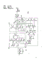
When Fig. 1 represents real work of the present invention and a three-phase power line system coupled;
The simplification line map of the H field coupler that Fig. 2 is in the preferred embodiments of the invention to be adopted;
Fig. 3 is the simplification line map of signal coupler used in the preferred embodiment of the invention;
Fig. 4 is the more detailed circuit diagram of H shown in Figure 2 field coupler;
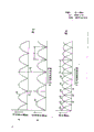
Fig. 5 A represents the variation amplitude of voltage signal on the power line that standing wave phenomena causes;
Fig. 5 B represents to have the current signal that changes on the power line of standing wave phenomena;
Fig. 6 represents to present electric current and the two kinds of signals of voltage on the power line of standing wave phenomena.
United States Patent (USP) No. 3911415 (being presented to White on October 7th, 1975) discloses a kind of distributed network power line carrier communication system, and this system can be used for independent power consumer is communicated with the central station.Frequency translation and signal activate the centre position that repeater is connected this network again, so that come the relaying carrier signal with different frequency.The United States Patent (USP) of issuing White on March 2nd, 1976 discloses a kind of distributed network power line communication system No. 3942168, and this system comprises a central communication terminal on the branch station that distributes.This central authorities' communication terminal is connected with telecommunication terminal on some electric distribution power lines when signal and communication.Be presented in November 2 nineteen eighty-two Mel literary composition (Melvin) No. 4357598 patent disclosure of United States Patent (USP) a kind of three-phase power distribution network communication system that comprises several remote devices, some remote device is used as signal repeater.Each signal repeater at least with three-phase conducting wire in two-phase be coupled, and comprise that signal that response coupling comes produces the circuit of composite signal.The United States Patent (USP) that on June 29th, 1976 was presented to people such as White discloses a kind of distribution network power line communication system No. 3967264, this system is divided into the communications zone that can look for, and these zones are determined by the repeater on the distribution transformer that is placed in distribution network.First repeater can be carried out the addressing of uniqueness by a request signal.The United States Patent (USP) that was presented to the York on January 24th, 1984 discloses a kind of distribution network communication system that has the variable information passage for No. 4427968.Each of several signal repeaters all is connected with certain remote terminal by a distribution network, each signal repeater includes passage and effect sign indicating number and unique address sign indicating number of storage, is addressed so that each signal repeater can be used as a terminal part again.United States Patent (USP) should be inquired about reference No. 3911415, No. 3942168, No. 4357598, No. 3967264 and No. 4427968, so that obtain more complete understanding.
Each class methods that modulated signal is injected into power line are well-known among those skilled in the art.The United States Patent (USP) that is presented to Ge Jiaer (Gajjar) April 6 nineteen eighty-two discloses a kind of device that carrier frequency signaling information is joined the distribution transformer primary coil No. 4323882.Equally, all kinds of receiver structures of received signal also are on record to those skilled in the art from a power line communication system.Be presented to October 19 nineteen eighty-two people such as Philips No. 4355303 patent disclosure of the U.S. a kind of receiver that is used for the distribution network power line carrier communication system, this receiver and an electrical power distribution line magnetic couplings.It includes a reception amplifier circuit, and this circuit comprises automatic gain control circuit, produces saturated with the reception electronic device on the feedback circuit that prevents to be used for determining to gain.Be presented to May 3 nineteen eighty-three white (Pai) No. 4382248 patent disclosure of the U.S. a kind of remote-control device that is used for polyphase electric power distribution network communication system.It comprises a circuit that receives independently by each communication signal of powerline systems phase line carrying.This receiving circuit responds the input signal that each signal that receives produces a serial form.
When signal after a power line communication system receives, this signal must be through demodulation so that the information that translates wherein to be comprised.According to employed particular modulation scheme, the type of modulation to the greatest extent can be varied.If adopt a phase shift keying modulating system, the demodulator of various type can both be adopted.No. 26624, European patent (being No. the 4311964th, the United States Patent (USP) that is presented to bohr gold (Bolkin) January 19 nineteen eighty-two) discloses the some phase-shift keying demodulators that are used for power line communication system, this demodulator comprises the device that the positive-negative polarity sample of some carrier wave segmentations is carried out sequential processes, and these some carrier wave segmentations are created within each carrier data symbol.Sample provides a binary coded signal like this, and to produce corresponding to the first and second phase angle vector signals, this signal phase Calais on several data symbols produces reference phase angle signal vector signal.The United States Patent (USP) that is presented to bohr gold (Bolkin) April 5 nineteen eighty-three discloses a kind of follow-on demodulator No. 437928, and it can be used for adopting the system of phase-shift keying demodulation method.For it being obtained more complete understanding, should be with reference to United States Patent (USP) No. 4355303, No. 4382248 and EPC patent 26624(4311964) and No. 4379284.
This method has been utilized voltage and the inconsistent favourable characteristics of current signal phase place under typical standing wave situation.If produce a voltage signal node a bit on, a receiver is coupled with power line, so just generation current signal antinode on same position.If can design a device of received current and two kinds of signals of voltage from the transmission line, Stationary Wave can be avoided.Further, if the voltage and current signal is compared, come to determine the strongest signal, no matter the specific position that produces standing wave how, receiver can be effectively same.In addition, also do not have a position to be used for detecting the voltage and current signal, and give a device to compare these signals, select signal the strongest among both these two signals.
This method relates generally to a kind of like this needs, has been the solution Stationary Wave, needs to detect along the locational voltage and current signal of any specific physical on the transmission line.To each the phase conductor working voltage coupling of three-phase power wire system, the center line to power line adopts the electric current coupling simultaneously.This has just utilized this favourable fact, that is: in standing wave mode, voltage and current all can be suppressed.But standing wave but can not make these two signals be suppressed on the same physical location of transmission line.
Each bar of three-phase conducting wire all is connected with a common point.This common point is connected with a receiver with an input when signal and communication.Three-phase signal is to produce a composite voltage signal to the influence of the common connection of a common point, and this signal has been represented a kind of combination of three-phase signal.Between points of common connection and receiver inlet, be connected with a signal coupler.The effect of this coupler is when the signal of upper frequency key passes through receiver inlet, makes the power line frequency ground connection of 60Hz.This part of the present invention provides a single composite voltage signal that receives from the powerline systems three-phase conducting wire.
H field coupler when work and the center conductor of powerline systems link.It uses a ferrite core, and has some circle coils to twine on it.This core assembly is placed on the position near center conductor, and a current signal is provided for second input of receiver.Thereby this receiver just had two signal inputs to compare, to select the strongest signal.Be coupled with power line if this device is at voltage signal on the position at node or zero point, typical standing wave situation has appearred in hypothesis so, and current signal just will be on a current wave antinode.So this receiver and relevant circuit thereof have two to its signal of sending.If voltage signal a little less than, current signal is then stronger, vice versa, no matter the particular location that acceptor circuit and transmission line are coupled is for where, one of two signals will come out according to their relative intensities are selected, thereby can successfully improve reception.
In the acceptor circuit also application with signal transmission capabilities, the present invention then utilizes the common ground in the middle of transmission.The output of a transmitter links to each other with this common ground when signal and communication, and the signal that the modulated that will amplify is crossed is injected on the power line by the phase place coupler that is connected between common ground and the phase conductor.Open reception and the emitter of just providing that this place is done like this, is being provided under the situation of transceiver.
The explanation of recommended embodiment has marked same reference numbers to identity element in institute's drawings attached from start to finish.
Fig. 1 represents a three-phase power wire system 10.The present invention is connected with powerline systems 10 in signal and communication when making transceiver 12 work.Transceiver 12 can be included in central communication unit, and (within CCU, repeater and other device, these devices are coupled mutually with each of three-phase power line in signal and communication, and purpose is will be incorporated in the power line communication system.
Among Fig. 1, transceiver 12 has 3 signal input port: S
1, S
2And S
3, by these input ports, modulated signal can be received by transceiver before filtering and hard-limiting.As mentioned above, the at first filtering of power line communication signal is being carried out being subjected to hard-limiting before the demodulation to the information that enters then.
When transceiver 12 has 3 input port S
1, S
2And S
3The time, it can be configured to optimum signal in three entering signals is selected, so that the structure of probability the best of the information that will suitably receive and import, these input informations are to be added on the triple line of powerline systems by a distance transmitter.
The present invention uses a signal coupler 14, or SCU, and purpose is that φ a, φ b and φ c in transceiver and the three-phase are coupled.In recommended embodiment of the present invention, each in the three-phase is all closed electric capacity by one mutually and is connected with a common point CP.As shown in Figure 1, coupling capacitor CC1 is connected in electric communication between A and the points of common connection CP.Equally, coupling capacitor CC2 is connected in electric communication between B and the points of common connection CP, coupling capacitor CC3 be connected on and common point CP between.By common point CP is connected with an input of signal coupler 14, this signal coupler receives the composite voltage signal of each each signal of going up mutually in the three-phase of representing powerline systems 10.Should understand that will represent a signal by the composite signal that signal coupler 14 receives, this voltage of signals level amplitude has been represented three signals of powerline systems 10.The amplitude of the composite signal that is received by coupler 14 on online 16 is between the lowest amplitude and high-amplitude of three-phase conducting wire of powerline systems 10.As shown in Figure 1, signal coupler 14 also is connected with the center conductor of three-phase power wire system 10.
Signal coupler 14 in signal and communication by the input S of a coaxial cable and transceiver 12
3Be connected, this coaxial cable has a center conductor 20 and a screen 22 that links to each other with ground by line 24.When being connected with this circuit, transceiver 12 receives the signal of a representative in the composite signal at tie point CP place on online 20.Signal coupler 14 will contrast Fig. 3 and further describe.
As shown in Figure 1, the present invention can also use H field coupler 30, and this coupler is connected with the center line N of power line communication system 10 in signal and communication.This H field coupler 30 uses a ferrite antenna 32, this antenna be tuned on the frequency of the carrier signal that receives from power line 10.As mentioned above, in the typical case who is applicable to power line communication system of the present invention used, carrier frequency was 12.5 kilocycles.The input S of a coaxial cable and transceiver 12 is passed through in the output of H field coupler 30 in signal and communication
1Be connected, this cable has a center line 34 and a screen 36, and this screen is connected with ground by line 38.Coupler 30 pairs of transceivers 12 in H field provide an input signal, as shown in Figure 1, and make transceiver 12 will select its input S
1And S
2In two signals that receive one preferably.By input S
1The signal of receiving is a current signal, by input S
3The signal of receiving is a voltage signal, if transceiver 12 is provided with one the 3rd input, as S
2, it is ground connection suitably, to prevent by not being subjected to the additional electrical noise jamming in transceiver 12 operate as normal.
As appreciable among Fig. 1, give transceiver 12 supply of current and two kinds of signals of voltage.The higher probability of the signal that the amplitude that this line construction of the present invention provides reception to be suitable for demodulation is enough big appears in the various situations of a standing wave phenomena in powerline systems 10.If at transceiver 12 and power line 10 voltage signal extremely low (because standing wave) on the contact mutually, current signal can be very high, and the signal that is received by H field coupler 30 will provide an input signal that has the acceptable amplitude of proper solution timing.If, on the contrary, transceiver 12 is connected on the low-down position of current signal of powerline systems 10, voltage signal will be very high, and signal coupler 14 will provide an enough big voltage signal of amplitude that is suitable for demodulation, therefore, line construction shown in Figure 1 as can be seen can be from power line 10 received currents and two kinds of signals of voltage, and exist under the standing wave situation, greatly improve reception and have enough big amplitude, be suitable for the probability of the signal of demodulation.
Have a look Fig. 5 A and 5B earlier, standing wave phenomena is expressed as along the function of the distance of power transmission line.For example, the voltage signal intensity shown in Fig. 5 A is passed through node and antinode in turn.Voltage signal is decayed widely on each nodal point, and under extreme case, signal strength signal intensity can go to zero.Otherwise the antinode of voltage signal is place's amplitude maximum in the middle of two node.
In Fig. 5 B, current signal strength is expressed as along the function of the electric power transfer linear distance that produces standing wave phenomena.Just as the skilled personnel to understand, when the situation of standing wave, the phase place of electric current and voltage signal staggers; That is, the node of voltage signal appears at along on the point of the antinode that current signal is arranged on the power transmission line.For example, the P1 point on power transmission line, voltage signal is in the node place, and current signal is the antinode place.Therefore, the P1 point has been represented a position that is difficult to receive enough big voltage signal, and current signal is but located peak value.On power transmission line the situation at P2 point place antithesis, in the example of typical standing wave situation, the distance D between node is approximately 7.4 miles.Therefore, P1 among Fig. 5 A and the 5B and P2 dot spacing are from being approximately 10 miles.
By two kinds of signals of voltage and current that power transmission line provides, it is enough big signal that the present invention makes a transceiver no matter it can both receive amplitude on which position of power line.If for example transceiver 12 is connected on the P1 point place of power line, voltage signal will be the low-voltage that can not receive.Yet at the P1 point, current signal strength is in peak value, and a signal that amplitude is enough big is provided, and makes it to be suitable for demodulation.On the contrary, if transceiver 12 is connected on the power line P2 point, current signal strength is just too low and can not receive, not demodulation it.Yet at the P2 point, voltage signal is in peak value, allows transceiver 12 to receive the enough large-signal of amplitude that are suitable for demodulation.
As described previously, the present invention allows transceiver 12 received currents and two kinds of signals of voltage, and the various technology that can adopt those skilled in the art to understand select stronger in two signals one to be used for the signal demodulation.Fig. 6 represents to have voltage signal 40 and the current signal 42 on the power transmission line of standing wave phenomena.Because transceiver 12 of the present invention can be selected between electric current and voltage signal, select the abundant big signal of the amplitude that can be used for demodulation, solid line shown in Fig. 6 shows the signal of being selected by transceiver microprocessor logic.For example, between X1 and X2 point, voltage signal 40 is than current signal 42 height.Therefore, receive the voltage signal that comes from signal coupler 14 and have higher amplitude than the current signal of receiving from H field coupler 30 42.Yet between X2 point X3 point, current signal 42 will be than voltage signal 40 height.Therefore, the signal that the input S1 of transceiver 12 receives from H field coupler 30 will be represented stronger two signals one, and by demodulation it.Fig. 2 has represented to be used for the simplification line map of H of the present invention field coupler 30.Ferrite antenna 32 is connected with band pass filter 50 in signal and communication; Band pass filter 50 is connected to successively and connects a trap filter and amplifying circuit 52 in the signal and communication.H field coupler 30 also has automatic gain control circuit 54 and high-frequency isolation coil 56.Provide a direct current voltage VDC by a direct current power supply (not being shown among Fig. 2).Ferrite antenna 32 is connected on the input of H field coupler 30 by line 60 and 62, and the coaxial cable that the output of H field coupler 30 is made up of center conductor 34 and grounding shell 36 is received on the transceiver 12.
Signal coupler (SCU) comprises a signal coupling transformer 64 of its output signal warp 20 and 22 being passed to the input S3 of transceiver 12.An earial drainage coil 66 and an arc protection of pipe device 68 are in parallel with this signal coupling transformer 64.The input of signal coupler 14 is connected on the common point CP, and there are three coupling capacitance CC1 at CP point place, and CC2 and CC3 form the three-phase φ a of signal coupler 14 and power line 10, the coupling between φ b and the φ c.Signal coupler earial drainage coil 66 plays a high pass filter, so that remove the 60Hz transmission frequency from the signal of receiving at the CP interface.Electric arc tube protector 68 is to be used for providing luminous protection for system.Signal coupling transformer 64 is carrier current transformers, is used for high-frequency signal is received on the line.
Fig. 4 represented H shown in Figure 2 field coupler 30 than detailed circuit diagram.Resemble among Fig. 4 appreciablely, H field coupler 30 comprises four essential parts shown in Fig. 2.Band pass filter circuit 50 is connected in signal and communication on the coupling inductance L1, and L1 simulates ferrite antenna 32 discussed above.Notch filter links to each other with band pass filter 50 in electric communication with amplifying circuit 52.And its output connects the direct voltage source of filtering of a band and AC coupled parts 70.This voltage source plays the similar functions of high-frequency isolation coil 56 shown in Fig. 2 and current and power supply VDC.Automatic gain control circuit 54 also is shown among Fig. 4.Used frame of broken lines is to mark to be used for the specific electronic unit of each function of representing in execution graph 2 reduced graphs among Fig. 4, and H field coupler 30 is connected on the coaxial cable, and the center conductor 34 of this cable and shell 36 provide a signal for the input S1 of transceiver 12.
Be similar to ferrite antenna 32 at band pass filter 50 and its function class of inductor L1() between, capacitor C15 and resistance R 15 provide input filtering between ferrite antenna 32 and band pass filter 50.Use in the application-specific of 12.5KHz carrier frequency in the present invention, resistance R 15 has the resistance of 3.3K Ω, and capacitor C15 has 0.27 μ F value.But, will be appreciated that for another frequency, will select different parameters of operating part for use.
Have a look Fig. 5 A and 5B again, clearly, voltage signal 40 is the signals that detected by the primary wires φ a, the φ b that are connected on power line 10 by coupling capacitor C1, C2 and C3 and the signal coupler 14 on the φ c.Same obvious is that current signal 42 is by ferrite antenna 32 and corresponding H field coupler 30 detected signals.
As implied above, transceiver 12 is connected on the characteristics on the power line 10, the intensity of voltage and current signal when determining to have standing wave phenomena.As shown in Figure 1, the present invention allows transceiver 12 to be connected in such a way on the power line 10.Transceiver 12 can receive two kinds of input signals of voltage and current.This circuit makes transceiver select stronger in two signals one to be used for demodulation.For example, if transceiver 12 is connected on the P1 point of power transmission line (indicating as Fig. 5 A and 5B), voltage signal 40 can be extremely low, and can not provide abundant big being suitable for to separate the signal that calls.Yet at the P1 point, current signal strength is its maximum amplitude, and from H field coupler 30, a signal of receiving at the input S1 of transceiver 12 will be supplied with one and separate the enough big signal of amplitude that calls.
Come referring to Fig. 6, solid line is represented voltage 40 and electric current 42 signal sections chosen by transceiver microprocessor logic again.Be connected on ad-hoc location on the power transmission line according to transceiver 12, based on its relative amplitude, voltage or current signal are selected again.As clearly drawing by solid line among Fig. 6, the signal strength signal intensity that the present invention provides for transceiver 12 always the maximum signal effective value at least 70.71%.Though, obviously loss can appear in powerline systems 10 of the present invention and transceiver 12 between tie point, no matter transceiver 12 is connected on which ad-hoc location of power transmission line, the present invention all can provide enough big input signal to transceiver.
The present invention has provided a power line communication device, and this device can be connected in the powerline systems transceiver when signal is logical.A preferable embodiment of the present invention is to utilize several coupling capacitors that each phase of the three-phase of powerline systems all is connected on the common ground.This common ground is received on the input of transceiver by signal coupler.This circuit structure provides a voltage signal to transceiver.The present invention also can utilize the H field coupler of the antenna of a ferrite core to receive on the center line of three-phase power wire system by one in signal and communication.When H field coupler and signal coupler were connected on the wireless set, each of these devices can both be connected on the input separately of transceiver, so that provide two signals.Transceiver logic just can select to be suitable for separating the signal of the high amplitude of calling thus.
The numerical value of other elements shown in Fig. 4 is listed in the following table 1.Yet, will be understood that these component parameters only represent to be used for specific prototype of the present invention, and its scope had no restriction.
Table 1

Claims (15)
1, a kind of remote-control device that can in power line communication system, realize communication, this remote-control device comprises:
Receiving system;
Voltage signal is coupled to first on the point (CP) device (Fig. 1,3(CC1, CC2, CC3)) from all three-phases of three-phase power line;
With the device (14,16,20) on the make a point first input end (S3) of linking said receiving system, said jockey provides a composite voltage signal (Fig. 5 A(40) for said reception input); It is characterized in that having:
Current signal is coupled to second kind of device of second input of said receiver from powerline systems; And said receiving system comprises the device that one of the said composite voltage signal of choosing and said current signal is carried out demodulation.
2, the device with said receiving system that requires as claim 1 further comprises:
Select one of them device of said composite voltage signal and said current signal according to the relative intensity of said composite voltage signal and said current signal.
3, the remote-control device that requires as claim 2, wherein: said choice device has a microprocessor logic.
4, as claim 1,2 or 3 desired devices, wherein said second coupling device comprises that a H field coupler is connected on the center conductor (N) of said three-phase power line.
5, as claim 1,2 desired devices, wherein: said jockey comprises a solid-state signal coupler.
6, a kind of transceiver that is used for the three-phase power communication system comprises:
R-T unit (Fig. 1 (12)) with a receiving system; When signal and communication; Has the first input end (S3) and second input (S1) that can be connected that to receive on the said three-phase power line with the center conductor (N) of said three-phase power line;
Voltage signal is coupled to first device (Fig. 1,3(14)) of said first input end from said three-phase; It is characterized in that having:
Current signal is coupled to second device (Fig. 1,2,4(30)) of said second input from said neutral conductor;
The said voltage signal that comes from said three-phase form a composite voltage signal device (CC1, CC2, CC3); And R-T unit (12) comprises and selects one of them device of said composite voltage signal and said current signal, the device that the signal of choosing is carried out demodulation is with a transmitter with output of the three-phase that can be connected said power line in signal and communication.
Applications Claiming Priority (2)
| Application Number | Priority Date | Filing Date | Title |
|---|---|---|---|
| US663,251 | 1984-10-22 | ||
| US06/663,251 US4668934A (en) | 1984-10-22 | 1984-10-22 | Receiver apparatus for three-phase power line carrier communications |
Publications (2)
| Publication Number | Publication Date |
|---|---|
| CN85109644A CN85109644A (en) | 1986-07-30 |
| CN1004676B true CN1004676B (en) | 1989-06-28 |
Family
ID=24661035
Family Applications (1)
| Application Number | Title | Priority Date | Filing Date |
|---|---|---|---|
| CN85109644.1A Expired CN1004676B (en) | 1984-10-22 | 1985-10-21 | Apparatus for three-phase power line carrier communications |
Country Status (8)
| Country | Link |
|---|---|
| US (1) | US4668934A (en) |
| JP (1) | JPS61101127A (en) |
| KR (1) | KR860003716A (en) |
| CN (1) | CN1004676B (en) |
| AU (1) | AU586833B2 (en) |
| CA (1) | CA1246709A (en) |
| ES (1) | ES8705173A1 (en) |
| ZA (1) | ZA857843B (en) |
Families Citing this family (94)
| Publication number | Priority date | Publication date | Assignee | Title |
|---|---|---|---|---|
| US6452482B1 (en) * | 1999-12-30 | 2002-09-17 | Ambient Corporation | Inductive coupling of a data signal to a power transmission cable |
| US4668934A (en) * | 1984-10-22 | 1987-05-26 | Westinghouse Electric Corp. | Receiver apparatus for three-phase power line carrier communications |
| CH671658A5 (en) * | 1986-01-15 | 1989-09-15 | Bbc Brown Boveri & Cie | |
| US4714912A (en) * | 1986-12-31 | 1987-12-22 | General Electric Company | Single-conductor power line communications system |
| US4890089A (en) * | 1988-11-25 | 1989-12-26 | Westinghouse Electric Corp. | Distribution of line carrier communications |
| US4903006A (en) * | 1989-02-16 | 1990-02-20 | Thermo King Corporation | Power line communication system |
| FR2682837B1 (en) * | 1991-10-17 | 1994-01-07 | Electricite De France | DIRECTIVE SEPARATOR-COUPLER CIRCUIT FOR MEDIUM FREQUENCY CARRIER CURRENTS ON LOW VOLTAGE ELECTRIC LINE. |
| EP0748480A1 (en) * | 1992-06-30 | 1996-12-18 | Electronic Innovators, Inc. | Distributed intelligence engineering casualty and damage control management system using an ac power line carrier-current lan |
| EP0604678B1 (en) * | 1992-12-28 | 1998-07-29 | Landis & Gyr Technology Innovation AG | Operation method for a receiver fed with information transmitted over electric supply network and arrangement for carrying it |
| JP3071220B2 (en) * | 1994-04-25 | 2000-07-31 | フォスター−ミラー インク | Self-powered power line sensor |
| US5818821A (en) * | 1994-12-30 | 1998-10-06 | Intelogis, Inc. | Universal lan power line carrier repeater system and method |
| US5694108A (en) * | 1996-05-01 | 1997-12-02 | Abb Power T&D Company Inc. | Apparatus and methods for power network coupling |
| US7158012B2 (en) * | 1996-11-01 | 2007-01-02 | Foster-Miller, Inc. | Non-invasive powerline communications system |
| US5870016A (en) * | 1997-02-03 | 1999-02-09 | Eva Cogenics Inc Euaday Division | Power line carrier data transmission systems having signal conditioning for the carrier data signal |
| US5864284A (en) * | 1997-03-06 | 1999-01-26 | Sanderson; Lelon Wayne | Apparatus for coupling radio-frequency signals to and from a cable of a power distribution network |
| US5978371A (en) * | 1997-03-31 | 1999-11-02 | Abb Power T&D Company Inc. | Communications module base repeater |
| US5933073A (en) * | 1997-07-07 | 1999-08-03 | Abb Power T&D Company Inc. | Apparatus and methods for power network coupling |
| US5952914A (en) * | 1997-09-10 | 1999-09-14 | At&T Corp. | Power line communication systems |
| DE19823234A1 (en) * | 1998-05-25 | 1999-12-02 | Abb Research Ltd | Device and method for data transmission or signal decoupling in current conductors |
| US6480510B1 (en) | 1998-07-28 | 2002-11-12 | Serconet Ltd. | Local area network of serial intelligent cells |
| GB9822097D0 (en) * | 1998-10-09 | 1998-12-02 | Ir Buro Vanderveen | Power transformer with internal differential mode distortion cancellation |
| US6677743B1 (en) | 1999-03-05 | 2004-01-13 | Foster-Miller, Inc. | High voltage powerline sensor with a plurality of voltage sensing devices |
| AU784517B2 (en) * | 1999-11-15 | 2006-04-27 | Ge Security, Inc. | Highly reliable power line communications system |
| US7154382B2 (en) * | 1999-12-30 | 2006-12-26 | Ambient Corporation | Arrangement of inductive couplers for data communication |
| WO2001054297A1 (en) * | 2000-01-20 | 2001-07-26 | Current Technologies, Llc | Method of isolating data in a power line communication network |
| US6947854B2 (en) * | 2000-02-29 | 2005-09-20 | Quadlogic Controls Corporation | System and method for on-line monitoring and billing of power consumption |
| US6549616B1 (en) | 2000-03-20 | 2003-04-15 | Serconet Ltd. | Telephone outlet for implementing a local area network over telephone lines and a local area network using such outlets |
| JP2004512702A (en) * | 2000-04-14 | 2004-04-22 | カレント・テクノロジーズ・エルエルシー | Digital communication using medium voltage distribution lines |
| US6965302B2 (en) | 2000-04-14 | 2005-11-15 | Current Technologies, Llc | Power line communication system and method of using the same |
| US6998962B2 (en) | 2000-04-14 | 2006-02-14 | Current Technologies, Llc | Power line communication apparatus and method of using the same |
| US7103240B2 (en) * | 2001-02-14 | 2006-09-05 | Current Technologies, Llc | Method and apparatus for providing inductive coupling and decoupling of high-frequency, high-bandwidth data signals directly on and off of a high voltage power line |
| US6456192B1 (en) | 2000-04-19 | 2002-09-24 | Phonex Broadband Corporation | Method and system for power line null detection and automatic frequency and gain control |
| US6842459B1 (en) | 2000-04-19 | 2005-01-11 | Serconet Ltd. | Network combining wired and non-wired segments |
| AU2001253674A1 (en) * | 2000-04-19 | 2001-11-07 | Current Technologies, Llc | Method and apparatus for interfacing rf signals to medium voltage power lines |
| US6839571B2 (en) * | 2000-05-19 | 2005-01-04 | Xg Technology, Llc | RF shielding design for wireless high-speed internet access system |
| US7248148B2 (en) * | 2000-08-09 | 2007-07-24 | Current Technologies, Llc | Power line coupling device and method of using the same |
| US6980089B1 (en) | 2000-08-09 | 2005-12-27 | Current Technologies, Llc | Non-intrusive coupling to shielded power cable |
| US7245201B1 (en) | 2000-08-09 | 2007-07-17 | Current Technologies, Llc | Power line coupling device and method of using the same |
| US6856647B1 (en) | 2000-10-17 | 2005-02-15 | General Electric Company | Methods and systems for neutral-to-ground communication |
| EP1371219A4 (en) | 2001-02-14 | 2006-06-21 | Current Tech Llc | Data communication over a power line |
| US7596459B2 (en) | 2001-02-28 | 2009-09-29 | Quadlogic Controls Corporation | Apparatus and methods for multi-channel electric metering |
| US7245472B2 (en) * | 2001-05-18 | 2007-07-17 | Curretn Grid, Llc | Medium voltage signal coupling structure for last leg power grid high-speed data network |
| US7053756B2 (en) * | 2001-12-21 | 2006-05-30 | Current Technologies, Llc | Facilitating communication of data signals on electric power systems |
| WO2003063381A1 (en) * | 2002-01-24 | 2003-07-31 | Ascom Powerline Communications Ag | Coupling device |
| US7102478B2 (en) | 2002-06-21 | 2006-09-05 | Current Technologies, Llc | Power line coupling device and method of using the same |
| US6982611B2 (en) * | 2002-06-24 | 2006-01-03 | Current Technologies, Llc | Power line coupling device and method of using the same |
| FR2843254A1 (en) * | 2002-08-01 | 2004-02-06 | Pierre Noel Guy Barre | Modem/electrical distribution network connection mechanism having HF modulated signals branching wires connected with capacitor neutral coupled and high/band pass filter connected conductor plane/neutral. |
| US7132819B1 (en) | 2002-11-12 | 2006-11-07 | Current Technologies, Llc | Floating power supply and method of using the same |
| IL152824A (en) | 2002-11-13 | 2012-05-31 | Mosaid Technologies Inc | Addressable outlet and a network using same |
| US7076378B1 (en) | 2002-11-13 | 2006-07-11 | Current Technologies, Llc | Device and method for providing power line characteristics and diagnostics |
| US6965303B2 (en) | 2002-12-10 | 2005-11-15 | Current Technologies, Llc | Power line communication system and method |
| US6980091B2 (en) | 2002-12-10 | 2005-12-27 | Current Technologies, Llc | Power line communication system and method of operating the same |
| US7075414B2 (en) | 2003-05-13 | 2006-07-11 | Current Technologies, Llc | Device and method for communicating data signals through multiple power line conductors |
| US7064654B2 (en) | 2002-12-10 | 2006-06-20 | Current Technologies, Llc | Power line communication system and method of operating the same |
| US6980090B2 (en) | 2002-12-10 | 2005-12-27 | Current Technologies, Llc | Device and method for coupling with electrical distribution network infrastructure to provide communications |
| US7046124B2 (en) | 2003-01-21 | 2006-05-16 | Current Technologies, Llc | Power line coupling device and method of using the same |
| IL160417A (en) | 2004-02-16 | 2011-04-28 | Mosaid Technologies Inc | Outlet add-on module |
| US7636396B1 (en) * | 2004-04-26 | 2009-12-22 | Dgi Creations, Llc | Method of testing remote power line carrier pick-up coil |
| US7606298B1 (en) * | 2004-04-26 | 2009-10-20 | Dgi Creations, Llc | Method of testing remote power line carrier pick-up coil |
| ATE550696T1 (en) * | 2004-08-04 | 2012-04-15 | Quadlogic Controls Corp | METHOD AND SYSTEM FOR COUPLING RADIO FREQUENCY SIGNALS TO MEDIUM VOLTAGE LINES WITH AN AUTOMATIC TUNING DEVICE |
| US7873058B2 (en) | 2004-11-08 | 2011-01-18 | Mosaid Technologies Incorporated | Outlet with analog signal adapter, a method for use thereof and a network using said outlet |
| US7804763B2 (en) * | 2005-04-04 | 2010-09-28 | Current Technologies, Llc | Power line communication device and method |
| US7307512B2 (en) * | 2005-04-29 | 2007-12-11 | Current Technologies, Llc | Power line coupling device and method of use |
| US20070194949A1 (en) | 2005-11-23 | 2007-08-23 | Quadlogic Controls Corporation | Systems and methods for electricity metering |
| US7366773B2 (en) * | 2006-01-30 | 2008-04-29 | Dgi Creations, Llc | Alternative communications paths for data sent over power line carrier |
| US7671701B2 (en) * | 2006-06-09 | 2010-03-02 | Current Technologies, Llc | Method and device for providing broadband over power line communications |
| US20080056338A1 (en) * | 2006-08-28 | 2008-03-06 | David Stanley Yaney | Power Line Communication Device and Method with Frequency Shifted Modem |
| DE102006049507B4 (en) * | 2006-10-17 | 2016-05-25 | Sew-Eurodrive Gmbh & Co Kg | Plant and method for operating a plant |
| US7795994B2 (en) * | 2007-06-26 | 2010-09-14 | Current Technologies, Llc | Power line coupling device and method |
| US7876174B2 (en) * | 2007-06-26 | 2011-01-25 | Current Technologies, Llc | Power line coupling device and method |
| US20090085726A1 (en) * | 2007-09-27 | 2009-04-02 | Radtke William O | Power Line Communications Coupling Device and Method |
| US8279058B2 (en) | 2008-11-06 | 2012-10-02 | Current Technologies International Gmbh | System, device and method for communicating over power lines |
| US20100111199A1 (en) * | 2008-11-06 | 2010-05-06 | Manu Sharma | Device and Method for Communicating over Power Lines |
| US8188855B2 (en) * | 2008-11-06 | 2012-05-29 | Current Technologies International Gmbh | System, device and method for communicating over power lines |
| CN101718831A (en) * | 2009-11-05 | 2010-06-02 | 中国石油大学(华东) | Method and device for detecting phase line of three-phase four-wire power transmission line |
| KR101052206B1 (en) * | 2011-01-17 | 2011-07-27 | 주식회사 유틸링크 | 3-phase integrated powerline coupling unit and powerline communication device having the coupling unit and surge protector |
| JP5746517B2 (en) * | 2011-02-23 | 2015-07-08 | 住友電気工業株式会社 | Power line communication system |
| US20120265355A1 (en) | 2011-04-15 | 2012-10-18 | Power Tagging Technologies, Inc. | System and method for single and multizonal optimization of utility services delivery and utilization |
| CA2874132A1 (en) | 2011-06-09 | 2013-01-17 | Dominion Energy Technologies, Inc. | System and method for grid based cyber security |
| EP2733860B1 (en) | 2011-07-13 | 2016-05-18 | Sumitomo Electric Industries, Ltd. | Communication system |
| US9380545B2 (en) | 2011-08-03 | 2016-06-28 | Astrolink International Llc | System and methods for synchronizing edge devices on channels without carrier sense |
| CN102320511B (en) * | 2011-08-23 | 2014-10-08 | 浙江科技学院 | Non-contact type information transmission method and device of elevator cage |
| US9407326B2 (en) | 2012-02-16 | 2016-08-02 | Enphase Energy, Inc. | Method and apparatus for three-phase power line communications |
| US9030302B2 (en) | 2012-02-16 | 2015-05-12 | Enphase Energy, Inc. | Method and apparatus for three-phase power line communications |
| US10097240B2 (en) | 2013-02-19 | 2018-10-09 | Astrolink International, Llc | System and method for inferring schematic and topological properties of an electrical distribution grid |
| US9124101B2 (en) * | 2013-04-02 | 2015-09-01 | Bel Fuse (Macao Commercial Offshore) Limited | Power supply having selectable operation based on communications with load |
| EP3008829B1 (en) | 2013-06-13 | 2019-08-07 | Astrolink International LLC | Inferring feeder and phase powering a transmitter |
| MX357831B (en) | 2013-06-13 | 2018-07-26 | Astrolink Int Llc | Non-technical losses in a power distribution grid. |
| CN103369905A (en) * | 2013-07-19 | 2013-10-23 | 杨海波 | Voltage capacitance carrier |
| JP2016527808A (en) | 2013-07-26 | 2016-09-08 | コーニンクレッカ フィリップス エヌ ヴェKoninklijke Philips N.V. | Signal pickup in an electrically non-contact manner |
| CN104184493A (en) * | 2014-08-13 | 2014-12-03 | 国家电网公司 | System for ensuring electric power line communication during breakdown or maintenance state of electric power circuit |
| WO2016070104A1 (en) | 2014-10-30 | 2016-05-06 | Bernheim Henrik Fernand | System and methods for assigning slots and resolving slot conflicts in an electrical distribution grid |
| CA2964393A1 (en) * | 2014-10-30 | 2016-05-06 | Dominion Energy Technologies, Inc. | System, method, and apparatus for grid location |
| JP6492256B2 (en) * | 2015-03-18 | 2019-04-03 | Necマグナスコミュニケーションズ株式会社 | Power line communication system and watt-hour meter used therefor |
Family Cites Families (17)
| Publication number | Priority date | Publication date | Assignee | Title |
|---|---|---|---|---|
| US3911415A (en) * | 1973-12-18 | 1975-10-07 | Westinghouse Electric Corp | Distribution network power line carrier communication system |
| US3967264A (en) * | 1975-01-31 | 1976-06-29 | Westinghouse Electric Corporation | Distribution network power line communication system including addressable interrogation and response repeater |
| US3942168A (en) * | 1975-01-31 | 1976-03-02 | Westinghouse Electric Corporation | Distribution network power line communication system |
| US4215394A (en) * | 1978-06-29 | 1980-07-29 | Oxy Metal Industries Corp. | Control logic for an inverter ripple controlled power system |
| US4311964A (en) * | 1979-09-21 | 1982-01-19 | Westinghouse Electric Corp. | Coherent phase shift keyed demodulator for power line communication systems |
| US4379284A (en) * | 1979-09-21 | 1983-04-05 | Westinghouse Electric Corp. | Coherent phase shift keyed demodulator for power line communication systems |
| FR2468249A1 (en) * | 1979-10-17 | 1981-04-30 | Enertec | INVERTER AND STATIC SIGNAL GENERATOR COMPRISING SUCH AN INVERTER |
| NL176889C (en) * | 1980-01-30 | 1985-06-17 | Nira Int Bv | PERSON SEARCH RECEIVER. |
| US4323882A (en) * | 1980-06-02 | 1982-04-06 | General Electric Company | Method of, and apparatus for, inserting carrier frequency signal information onto distribution transformer primary winding |
| US4390876A (en) * | 1980-07-25 | 1983-06-28 | Southern California Edison Co., Inc. | Electric utility demand limiting device and method |
| US4408186A (en) * | 1981-02-04 | 1983-10-04 | General Electric Co. | Power line communication over ground and neutral conductors of plural residential branch circuits |
| US4427968A (en) * | 1981-04-09 | 1984-01-24 | Westinghouse Electric Corp. | Distribution network communication system with flexible message routes |
| US4357598A (en) * | 1981-04-09 | 1982-11-02 | Westinghouse Electric Corp. | Three-phase power distribution network communication system |
| US4382248A (en) * | 1981-04-09 | 1983-05-03 | Westinghouse Electric Corp. | Remote device for a multi-phase power distribution network communication system |
| US4355303A (en) * | 1981-04-09 | 1982-10-19 | Westinghouse Electric Corp. | Receiver for a distribution network power line carrier communication system |
| US4473816A (en) * | 1982-04-13 | 1984-09-25 | Rockwell International Corporation | Communications signal bypass around power line transformer |
| US4668934A (en) * | 1984-10-22 | 1987-05-26 | Westinghouse Electric Corp. | Receiver apparatus for three-phase power line carrier communications |
-
1984
- 1984-10-22 US US06/663,251 patent/US4668934A/en not_active Expired - Fee Related
-
1985
- 1985-06-21 CA CA000484802A patent/CA1246709A/en not_active Expired
- 1985-10-10 AU AU48479/85A patent/AU586833B2/en not_active Ceased
- 1985-10-11 ZA ZA857843A patent/ZA857843B/en unknown
- 1985-10-21 CN CN85109644.1A patent/CN1004676B/en not_active Expired
- 1985-10-21 ES ES548057A patent/ES8705173A1/en not_active Expired
- 1985-10-22 KR KR1019850007796A patent/KR860003716A/en not_active Application Discontinuation
- 1985-10-22 JP JP60237172A patent/JPS61101127A/en active Pending
Also Published As
| Publication number | Publication date |
|---|---|
| CA1246709A (en) | 1988-12-13 |
| ES8705173A1 (en) | 1987-04-16 |
| ES548057A0 (en) | 1987-04-16 |
| ZA857843B (en) | 1986-05-28 |
| KR860003716A (en) | 1986-05-28 |
| US4668934A (en) | 1987-05-26 |
| JPS61101127A (en) | 1986-05-20 |
| AU586833B2 (en) | 1989-07-27 |
| AU4847985A (en) | 1986-05-01 |
| CN85109644A (en) | 1986-07-30 |
Similar Documents
| Publication | Publication Date | Title |
|---|---|---|
| CN1004676B (en) | Apparatus for three-phase power line carrier communications | |
| US5257006A (en) | Method and apparatus for power line communications | |
| US4016429A (en) | Power line carrier communication system for signaling customer locations through ground wire conductors | |
| US5406249A (en) | Method and structure for coupling power-line carrier current signals using common-mode coupling | |
| AU595884B2 (en) | Power line communication interference preventing circuit | |
| US4357598A (en) | Three-phase power distribution network communication system | |
| US4210901A (en) | Signal repeater for a distribution network communication system | |
| US4733389A (en) | Drop cable for a local area network | |
| JP5383749B2 (en) | Communication device and coupler for communication device | |
| JP2525886B2 (en) | Communications system | |
| US4745391A (en) | Method of, and apparatus for, information communication via a power line conductor | |
| US4317216A (en) | Bi-directional filter system for amplifying signals in separate frequency bands | |
| CN100477539C (en) | Coupler for coupling data signal to power transmission cable | |
| JPS58191536A (en) | Reproducer for power line communication device | |
| JP2005130519A (en) | Network and signal transmission method | |
| JPH10504948A (en) | Coupling telecommunication signals into balanced distribution networks. | |
| JPS5829013B2 (en) | Signal coupling circuit device for distribution line carrier communication system | |
| JP2003531551A (en) | Transmission system and method for power line communication | |
| EP0091824B1 (en) | Receiving circuit for a data transmission system | |
| US5581710A (en) | Full duplex communication on a single communication ring | |
| EP0098066A1 (en) | A data transmission system | |
| US6836508B1 (en) | Method and apparatus for using unintended radio frequency propagation in a network | |
| US1812624A (en) | Telephone and telegraph signaling system | |
| US1950127A (en) | Communication system | |
| JPH07235897A (en) | Power line communication equipment and power line communication network |
Legal Events
| Date | Code | Title | Description |
|---|---|---|---|
| C06 | Publication | ||
| PB01 | Publication | ||
| C10 | Entry into substantive examination | ||
| SE01 | Entry into force of request for substantive examination | ||
| C13 | Decision | ||
| GR02 | Examined patent application | ||
| C14 | Grant of patent or utility model | ||
| GR01 | Patent grant | ||
| C19 | Lapse of patent right due to non-payment of the annual fee | ||
| CF01 | Termination of patent right due to non-payment of annual fee |