The present invention comprises and relates to the theme of on December 22nd, 2004 to the Japanese patent application JP2004-371341 of Japan Patent office submission, and its full content is incorporated herein by reference.
Embodiment
Describe embodiments of the present invention below with reference to accompanying drawings in detail.
(first execution mode)
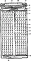
Fig. 1 has showed the cross-sectional structure according to the secondary cell of first embodiment of the invention.This secondary cell is so-called cylindrical battery, and has spiral winding electrode 20, wherein in battery case 11 inside with approximate hollow cylindrical, and banded negative pole 21 and banded positive pole 22 and the 23 stacked and coilings of barrier film therebetween.Battery case 11 is got by the iron of for example nickel plating.The one end sealing of battery case 11, and its other end opens wide.In the inside of battery case 11, a pair of insulation board 12 and 13 is arranged vertically with the periphery surface of reeling respectively, makes spiral winding electrode 20 be clipped between insulation board 12 and 13.
At the openend of battery case 11, battery cover 14, the relief valve mechanism 15 that is provided at battery cover 14 inside and PTC (positive temperature coefficient) device 16 are adhered to by liner 17 calkings.The inside of enclosed cell shell 11 thus.Battery cover 14 is for example made by the material with the materials similar of battery case 11.Relief valve mechanism 15 is electrically connected with battery cover 14 by PTC device 16.When by internal short-circuit, external heat etc., the internal pressure of battery reaches certain level or when bigger, and disc plate 15A returns and scratches (flip) and cut off electrical connection between battery cover 14 and the spiral winding electrode 20.When temperature raise, PTC device 16 limited electric current by increasing resistance value, thereby avoided producing unusual heat because of big electric current.Liner 17 is made by for example insulating material and its surface-coated has pitch.
For example, centrepin 24 is inserted in the center of spiral winding electrode 20.The negative wire 25 that is made by nickel etc. is connected with negative pole 21.The positive wire 26 that is made by aluminium etc. is connected with anodal 22.Negative wire 25 is welded on the battery case 11 and is electrically connected with it.Positive wire 26 is electrically connected with battery cover 14 by being welded on the relief valve mechanism 15.
Fig. 2 has showed the amplifier section of spiral winding electrode 20 shown in Fig. 1.Negative pole 21 has such structure, and wherein for example anode active material layer 21B is provided on the two sides of the negative electrode collector 21A with a pair of opposite face.Negative electrode collector 21A is made by for example metal forming such as copper (Cu) paper tinsel, nickel (Ni) paper tinsel and stainless steel foil.
Anode active material layer 21B comprises, and for example can insert and deviate from one or more negative materials of lithium as negative active core-shell material.As this negative material, for example, can enumerate and comprise and to form the metallic element of alloy and at least a material of metalloid element with lithium as element.This material can be simple substance, alloy or the compound of metallic element or metalloid element, or the material that has its one or more phases to small part.In the present invention, except the alloy that comprises two or more metallic elements, alloy also comprises the alloy that comprises one or more metallic elements and one or more metalloid elements.In addition, alloy can comprise nonmetalloid.Its structure comprises solid solution, eutectic crystal (eutectic mixture), intermetallic compound, reaches the wherein structure of its two or more coexistences.
As the metallic element or the metalloid element that can form alloy with lithium, for example, can enumerate magnesium (Mg), boron (B), aluminium, gallium (Ga), indium (In), silicon, germanium (Ge), tin, lead (Pb), bismuth (Bi), cadmium (Cd), silver (Ag), zinc (Zn), hafnium (Hf), zirconium (Zr), yttrium (Y), palladium (Pd), platinum (Pt) etc.
Specifically, as this negative material, preferably be contained in the metallic element of 14 families in the long period periodic table of elements or metalloid element material as element.At least a material that especially preferably comprises silicon and tin as element.The ability that silicon and tin have high insertion and deviates from lithium, and high-energy-density is provided.Specifically, for example, can enumerate simple substance, alloy or the compound of silicon; The simple substance of tin, alloy or compound; Or the material that has its one or more phases to small part.
As the alloy of silicon, for example, can enumerate at least a alloy that comprises tin, nickel, copper, iron (Fe), cobalt (Co), manganese (Mn), zinc, indium, silver, titanium (Ti), germanium, bismuth, antimony (Sb) and chromium (Cr) as the second outer element of silica removal.As the alloy of tin, for example, can enumerate at least a alloy that comprises silicon, nickel, copper, iron, cobalt, manganese, zinc, indium, silver, titanium, germanium, bismuth, antimony and chromium as the second outer element of detin.
As the compound of tin or the compound of silicon, for example, can enumerate the compound that comprises oxygen (O) or carbon (C).Except tin or silicon, compound also can comprise above-mentioned second element.
As the negative material that can insert and deviate from lithium, for example, but but can use material with carbon element such as graphite, non--graphitized carbon and graphitized carbon.In addition, this material with carbon element can use with above-mentioned negative material.The preferred material with carbon element that uses.Its reason is very little by the insertion of lithium and the changes in crystal structure deviating to cause, and for example, when material with carbon element uses with above-mentioned negative material, can obtain higher energy density, excellent cycle characteristics can be obtained, and function can be obtained thus as electric conductor.
Anode active material layer 21B can further comprise other negative active core-shell materials.In addition, anode active material layer 21B can comprise other materials such as adhesive and thickener.
In addition, negative pole 21 has the coating 21C that comprises lithium fluoride and lithium hydroxide on the surface of anode active material layer 21B.Ratio in coating 21C between lithium fluoride and the lithium hydroxide in such scope, the Li that in cation analysis, obtains wherein by flight time secondary ion mass spectrometry (TOF-SIMS)
2F
+To Li
2OH
+Peak intensity than (below be called Li
2F
+/ Li
2OH
+The peak intensity ratio) be 1 or bigger.Thereby, in negative pole 21, can suppress the oxidation of anode active material layer 21B, and can suppress the side reaction in the negative pole 21.In addition, the ratio in coating 21C between lithium fluoride and the lithium hydroxide preferably in such scope, Li wherein
2F
+/ Li
2OH
+The peak intensity ratio is 4 or bigger, because can obtain higher effect thus.The thickness of coating 21C is preferably 100nm or littler.Coating is thick more, and it is big more that impedance becomes.
Anodal 22 have wherein anode active material layer 22B for example is provided at structure on the two sides of the positive electrode collector 22A with a pair of opposite face.Positive electrode collector 22A is made by for example metal forming such as aluminium foil, nickel foil and stainless steel foil.
Anode active material layer 22B comprises, and for example, one or more can insert and deviate from the positive electrode of lithium as positive electrode active materials.If necessary, anode active material layer 22B can comprise electric conductor such as material with carbon element and adhesive such as polyvinylidene fluoride.As the positive electrode that can insert and deviate from lithium, for example, preferably comprise the lithium composite xoide or the lithium phosphate compounds of lithium and transition metal.The lithium composite xoide and the lithium phosphate compounds that comprise lithium and transition metal can produce high voltage, and can help high power capacity.
As lithium composite xoide or lithium phosphate compounds, preferably comprise at least a compound that is selected from cobalt, nickel, manganese, iron, aluminium, vanadium (V), titanium, chromium and copper as transition metal.Especially, preferably comprise at least a compound that is selected from cobalt, nickel and manganese.Its formula is by for example, Li
xMIO
2Or Li
yMIIPO
4Expression.In the formula, MI and MII represent one or more transition metals.The value of x and y changes according to the charging and the discharge condition of battery, and the value of x and y is usually in the scope of 0.05 ≦ x ≦ 1.10 and 0.05 ≦ y ≦ 1.10.
As the instantiation of the composite oxides that comprise lithium and transition metal, can enumerate lithium cobalt composite oxide (Li
xCoO
2), lithium nickel composite oxide (Li
xNiO
2), lithium/nickel/cobalt composite oxide (Li
xNi
1-vCo
vO
2(v<1)) or have the complex Li-Mn-oxide (Li of spinel structure
xMn
2O
4).As the lithium phosphate compounds, for example, can enumerate lithium iron phosphate compound (LiFePO
4) or ithium iron manganese phosphate compounds (LiFe
1-zMn
zPO
4(z<1)).
Barrier film 23 separates negative pole 21 with anodal 22, prevent to contact the short circuit current that causes by two electrodes, and allow lithium ion pass through.Barrier film 23 is made by for example synthetic resin perforated membrane or ceramic porous membrane, and this synthetic resin perforated membrane is made by polytetrafluoroethylene, polypropylene, polyethylene etc.Barrier film 23 can have wherein two or more above-mentioned porous membrane laminated structures.
Electrolyte as liquid electrolyte is immersed in the barrier film 23.Electrolyte comprises, for example, and solvent and the electrolytic salt that is dissolved in this solvent.If necessary, can comprise various additives.
As solvent, for example, can enumerate nonaqueous solvents such as propylene carbonate, ethylene carbonate, diethyl carbonate, dimethyl carbonate, 1,2-dimethoxy-ethane, 1,2-diethoxyethane, gamma-butyrolacton, oxolane, 1,3-dioxolanes (dioxolan), 4-methyl isophthalic acid, the linear carbonate of 3-dioxolanes, diethyl ether, sulfolane, methyl sulfolane, acetonitrile, propionitrile, vinylene carbonate, halogenation and the cyclic carbonate of halogenation.This solvent can use separately, maybe can use its two or more by mixing.
As electrolytic salt, for example, can enumerate lithium salts such as LiPF
6, LiBF
4, LiClO
4, LiAsF
6, LiB (C
6H
5)
4, LiCl, LiBr, LiCH
3SO
3, and LiCF
3SO
3As electrolytic salt, can use separately above-mentioned any one, maybe can be by mix using its two or more.
For example secondary cell can followingly be made.
At first, for example, on negative electrode collector 21A, form anode active material layer 21B.Anode active material layer 21B can form by two or more of for example vapour deposition process, liquid phase deposition, roasting method, coating or these methods.
As vapour deposition process, for example, can use physical deposition method or chemical deposition.Specifically, can adopt vaccum gas phase sedimentation method, sputtering method, ion plating, laser ablation method, hot CVD (chemical vapour deposition (CVD)) method, plasma CVD method, thermal spraying etc.As liquid phase deposition, can adopt known technology such as metallide and chemical plating.
Roasting method is such method: wherein for example with mixing such as granular negative active core-shell material, adhesives, this mixture is dispersed in the solvent, applies negative electrode collector with product, it is heat-treated under the temperature of the fusing point that is higher than adhesive etc.For roasting method, can adopt known technology such as atmosphere roasting method, reaction roasting method and hot pressing roasting method.Under the situation of coating, for example, anode active material layer 21B forms like this: by granular negative active core-shell material and adhesive etc. are mixed, mixture is dispersed in the solvent, applies negative electrode collector with product, be dried also compression molding.
In addition, form anodal 22 by on positive electrode collector 22A, forming anode active material layer 22B.The for example following formation of anode active material layer 22B.For example, particulate positive electrode active material, electric conductor and adhesive are mixed with the preparation cathode mix, this cathode mix is dispersed in the solvent.Then, apply positive electrode collector 22A, be dried and compression molding, so form anode active material layer 22B with product.
Then, negative wire 25 is attached to negative electrode collector 21A, and positive wire 26 is attached to positive electrode collector 22A.Subsequently, negative pole 21 and anodal 22 is reeled with the barrier film between it 23.The end of negative wire 25 is soldered to battery case 11, and the end of positive wire 26 is soldered to relief valve mechanism 15.The negative pole 21 of this coiling and the positive pole 22 of reeling are clipped between a pair of insulation board 12 and 13, and are included in the battery case 11.Afterwards, inject the electrolyte in the battery case 11, and battery cover 14, relief valve mechanism 15 and PTC device 16 are fixed to the open end of battery case 11 by liner 17 calkings.
Then, in electrolyte, add fluorochemical.For example, fluorochemical can be used for solvent.In addition, except being used for solvent, fluorochemical can be used as additive and adds to form coating 21C.Then, charge and discharge, and coating 21C electrochemically is formed on the surface of anode active material layer 21B.Ratio in coating 21C between lithium fluoride and the lithium hydroxide can be controlled by regulating charge condition such as charging current value.Thereby, finish the secondary cell shown in Fig. 1 and 2.
Can before the battery assembling, form coating 21C, be substituted in the battery assembling and electrochemically form coating 21C afterwards.For example, can on anode active material layer 21B, form coating 21C, maybe can electrochemically form coating 21C by using electrolyte by vapour deposition process etc.
In this secondary cell, when when charging, for example, lithium ion is deviate from and is inserted the negative pole 21 by electrolyte from anodal 22.When discharge, for example, lithium ion is deviate from and is inserted anodal 22 by electrolyte from negative pole 21.So, owing on the surface of negative pole 21, formed Li
2F
+/ Li
2OH
+Therefore peak intensity has suppressed the oxidation of anode active material layer 21B, and has suppressed the decomposition reaction of electrolyte in negative pole 21 than being 1 or bigger coating 21C.
Especially, when comprising at least a material as element during as negative active core-shell material that can form the metallic element of alloy and metalloid element with lithium, the activity of negative pole 21 uprises.Yet,, suppressed decomposition reaction effectively by coating 21C is provided on negative pole 21.
As mentioned above, according to this execution mode, because negative pole 21 has Li
2F
+/ Li
2OH
+Peak intensity can suppress the oxidation of anode active material layer 21B, and can suppress the decomposition reaction of electrolyte than being 1 or bigger coating 21C.Therefore, can improve battery behavior such as cycle characteristics.Especially, when comprising at least a material as element during that can form the metallic element of alloy and metalloid element with lithium, can obtain higher effect as negative active core-shell material.
(second execution mode)
Fig. 3 has showed the structure according to the secondary cell of second embodiment of the invention.This secondary cell is so-called lamination membranous type secondary cell.In this secondary cell, the spiral winding electrode 30 that is attached with negative wire 31 and positive wire 32 on it is included in the film packaging element 40.
For example, negative wire 31 and positive wire 32 with identical direction respectively from the inside directed outwards of packaging element 40.Negative wire 31 and positive wire 32 respectively by, for example, metal material such as aluminium, copper, nickel and stainless steel are made, and are respectively lamellar or netted.
Packaging element 40 is to be made by the rectangular aluminum laminated film, and for example in this film, nylon membrane, aluminium foil and polyethylene film combine in proper order with this.For example, packaging element 40 is so arranged so that the polyethylene film side is relative with spiral winding electrode 30, and by melting welding or adhesive outer rim separately is in contact with one another.Be used for preventing that adhesive film 33 that extraneous air is invaded is inserted between packaging element 40 and negative wire 31, the positive wire 32.Adhesive film 33 is to be made by the material that anticathode lead-in wire 31 and positive wire 32 have a contact performance, for example the vistanex of polyethylene, polypropylene, modified poly ethylene and modified polypropene.
Packaging element 40 can replace above-mentioned aluminium lamination press mold to make by the laminated film with other structures, high molecular weight membrane such as polypropylene or metal film.
Fig. 4 has shown along the cross-sectional structure of the line I-I of spiral winding electrode shown in Figure 3 30.In this spiral winding electrode 30, negative pole 34 and anodal 35 is stacked and reel with therebetween barrier film 36 and dielectric substrate 37.Its outermost is by boundary belt 38 protections.
Negative pole 34 has anode active material layer 34B wherein and is provided at structure on the two sides of negative electrode collector 34A.On the surface of anode active material layer 34B, form coating 34C.Anodal 35 have anode active material layer 35B wherein is provided at structure on the two sides of positive electrode collector 35A.Arrange and make anode active material layer 35B relative with anode active material layer 34B.The structure of negative electrode collector 34A, anode active material layer 34B, coating 34C, positive electrode collector 35A, anode active material layer 35B and barrier film 36 respectively with the similar of negative electrode collector 21A, anode active material layer 21B, coating 21C, positive electrode collector 22A, anode active material layer 22B and the barrier film 23 of above-mentioned first execution mode.
Dielectric substrate 37 is so-called gel states, and it comprises electrolyte and in order to keep the high-molecular weight compounds of electrolyte.This gel-like electrolyte is preferred, because can obtain high ionic conductivity, and can prevent battery drain thus.The similar of structure of electrolyte (that is, solvent, electrolytic salt etc.) and above-mentioned first execution mode.As high molecular weight material, for example, can enumerate ether high-molecular weight compounds such as poly(ethylene oxide) and contain the crosslinked body of poly(ethylene oxide), the polymer of vinylidene fluoride such as the copolymer or the polyacrylonitrile of polyvinylidene fluoride and vinylidene fluoride and hexafluoropropylene.Can use it a kind of, or use its two or more by mixing.Especially, consider oxidation-reduction stability, the high-molecular weight compounds that the expectation use is fluoridized such as the polymer of vinylidene fluoride.
For example, can following manufacturing secondary cell.
At first, as first execution mode, on negative electrode collector 34A, form anode active material layer 34B, and on positive electrode collector 35A, form anode active material layer 35B.Afterwards, apply anode active material layer 34B and anode active material layer 35B respectively with the precursor solution that comprises electrolyte, high-molecular weight compounds and mixed solvent.The volatilization mixed solvent is to form dielectric substrate 37.Then, for example, in electrolyte, add fluorochemical.Then, negative wire 31 is attached to negative electrode collector 34A, and positive wire 32 is attached to positive electrode collector 35A.Afterwards, negative pole 34 and anodal 35 is stacked and reel to obtain laminate with barrier film 36 therebetween.Boundary belt 38 is adhered to its outermost forms spiral winding electrode 30.Subsequently, for example, spiral winding electrode 30 is clipped between the packaging element 40, and makes the outer rim contact of packaging element 40, with sealing screw rolled electrode body 30 by thermofussion welding etc.Then, charge and discharge, and on the surface of anode active material layer 34B, electrochemically form coating 34C.Thereby Fig. 3 and secondary cell shown in Figure 4 have been finished.
In addition, secondary cell can followingly be made.At first, on negative electrode collector 34A, form anode active material layer 34B, and on positive electrode collector 35A, form anode active material layer 35B.Afterwards, negative wire 31 and positive wire 32 are attached to negative pole 34 and positive pole 35, itself and barrier film 45 are therebetween reeled to obtain laminate.Boundary belt 38 is adhered to its outermost, to form spiral winding electrode as the precursor of spiral winding electrode 30.Then, coiling body is sandwiched between the packaging element 40, outermost (except that a side) is carried out thermofussion welding obtaining a bag shape, and coiling body is included in the inside of packaging element 40.Subsequently, preparation comprises electrolyte, as being used for the electrolyte composition of matter of monomer, polymerization initiator and the other materials if necessary such as the polymerization inhibitor of the raw material of high-molecular weight compounds, and said composition is injected in the packaging element 40.Then, for example, in electrolyte, add fluorochemical.Afterwards, the openend thermofussion welding with packaging element 40 also seals.Then, the heating gains are so that monomer polymerization obtains high-molecular weight compounds.Form gel-like electrolyte layer 37 thus.Subsequently, charge and discharge, and on the surface of anode active material layer 34B, electrochemically form coating 34C.Thereby finish the secondary cell shown in Fig. 3 and 4.
In this embodiment, as first execution mode, coating 34C can form before the battery assembling.
This secondary cell and first execution mode are worked similarly and similar effects are provided.
(embodiment)
Further, will provide specific embodiments of the invention in detail below.
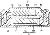
Make Coin shape secondary cell shown in Figure 5.In this secondary cell, negative pole 51 and positive pole 52 are stacked with barrier film 53 therebetween, and laminate is enclosed between pack case 54 and the packing cap 55.
(embodiment 1)
At first, by using silicon, adopt vaccum gas phase sedimentation method on the negative electrode collector 51A that makes by Copper Foil, to deposit the anode active material layer 51B that makes by silicon as negative active core-shell material.With product heat treatment under vacuum atmosphere.In addition, preparation lithium cobalt composite oxide (LiCoO
2) as positive electrode active materials.91 weight portion lithium cobalt composite oxide powders, 6 weight portions graphite, 3 weight portions as electric conductor are mixed as the polyvinylidene fluoride of adhesive, and mixture is dispersed in the N-N-methyl-2-2-pyrrolidone N-as solvent.Then, apply the positive electrode collector 52A that makes by aluminium foil, be dried, also form anodal 52 by the roll squeezer compression molding to form anode active material layer 52B then with product.
Subsequently, to carry out the negative pole that forms 51 of lamination and the positive pole 52 that forms with the barrier film of being made by many microporous polypropylene membranes 53 therebetween is placed on the pack case 54, inject electrolyte on it, packing cap 55 is placed on it, and by using liner 56 calking cocoons 54 and packing cap 55.For electrolyte, in embodiment 1, use by will be as the LiClO of electrolytic salt
4Concentration with 1mol/l is dissolved in wherein 4-fluoro-1, the electrolyte that obtains in 3-dioxolanes-2-ketone and diethyl carbonate the solvent with volume ratio 1:1 mixing, and using the electrolyte that as embodiment 1, obtains among the embodiment 2, except with 4,5-two fluoro-1,3-dioxolanes-2-ketone replaces 4-fluoro-1, beyond 3-dioxolanes-2-ketone.
Afterwards, charge and discharge, on negative pole 51, form coating 51C, and obtain the discharge capacity of circulation for the second time, the 30th circulation the capability retention of circulation for the second time and the charging and the discharging efficiency of circulation for the second time.Then, with constant current density 1mA/cm
2Charging reaches 4.2V up to cell voltage, and charges with constant voltage 4.2V then and reach 0.02mA/cm up to current density
2With constant current density 1mA/cm
2Discharge and reach 2.5V up to cell voltage.The results are shown in the table 1.
In addition, after the charging of carrying out 30 circulations and discharge, in argon gas atmosphere, divide electrolytic cell to take out negative pole 51.The negative pole 51 usefulness dimethyl carbonates that take out are cleaned vacuumize, the cation analysis of flight time secondary ion mass spectrometry of working of going forward side by side.For this analysis, use Ulvac-phi, the TFS-2000 of Inc..Analysis condition is a primary ion
197Au
+, ionic current 2nA (by the measured value of continuous bundle), weight range 1-1850amu and sweep limits 300 * 300 μ m
2The Li that obtains by this result
2F
+/ Li
2OH
+The peak intensity ratio is shown in Table 1, and the results are shown among Fig. 6 of embodiment 1.Fig. 6 uses for by the thickness from the about 1 μ m in the surface of being converted into silicon
197Au
+The spectrogram that ion sputtering obtains.Owing in Fig. 6, do not show the silicon Si that constitutes anode active material layer 51B
+The peak, find on the surface of anode active material layer 51B, to have formed the coating 51C that comprises lithium fluoride and lithium hydroxide.
(embodiment 3)
Assemble secondary cell as embodiment 1, except forming the coating 51C that comprises lithium fluoride and lithium hydroxide by vapour deposition process on anode active material layer 51B, and use ethylene carbonate to replace 4-fluoro-1,3-dioxolanes-2-ketone is used for beyond the electrolyte.In addition, as embodiment 1, obtain the discharge capacity of circulation for the second time, the 30th circulation to the capability retention of circulation for the second time and the charging and the discharging efficiency of circulation for the second time.The result also is shown in Table 1.Regulate the composition of coating 51C, make by regulating sedimentary condition, with Li
2F
+/ Li
2OH
+The peak intensity ratio becomes 1 or bigger, and the thickness of coating 51C is 100 μ m or littler.
(embodiment 4 to 6)
As embodiment 1, assemble secondary cell.Afterwards, as embodiment 1, the discharge capacity that acquisition circulates for the second time, the 30th circulation are to the capability retention that circulates for the second time and the charging and the discharging efficiency that circulate for the second time, except charging by change current density in charging and discharge and discharging.Current density in charging and discharge is 0.75mA/cm in embodiment 4
2, be 2mA/cm in embodiment 5
2, and be 5mA/cm in embodiment 6
2In addition, as embodiment 1, take out negative pole 51 and detect Li
2F
+/ Li
2OH
+The peak intensity ratio.The result also is shown in Table 1.
(embodiment 7 and 8)
As embodiment 1 or embodiment 2, assemble secondary cell.Afterwards, the same as embodiment 1 with 2, obtain the discharge capacity of circulation for the second time, the 30th circulation to the capability retention of circulation for the second time and the charging and the discharging efficiency of circulation for the second time, voltage is the 4.3V in charging.That is, with constant current density 1mA/cm
2Charging reaches 4.3V up to cell voltage, and charges with constant voltage 4.3V then and reach 0.02mA/cm up to current density
2In embodiment 7, use electrolyte similar to Example 1, and in embodiment 8, use electrolyte similar to Example 2.In addition, as embodiment 1, take out negative pole 51 and detect Li
2F
+/ Li
2OH
+The peak intensity ratio.The result also is shown in Table 1.
(embodiment 9 and 10)
As embodiment 1 or embodiment 2, assemble secondary cell.Afterwards, the same as embodiment 1 with 2, obtain the discharge capacity of circulation for the second time, the 30th circulation to the capability retention of circulation for the second time and the charging and the discharging efficiency of circulation for the second time, except changing charge condition.By applying pulse is that the 4.8V voltage of 100kHz is with constant current density 1mA/cm
2Charging reaches 4.2V up to cell voltage, and charges with constant voltage 4.2V then and reach 0.02mA/cm up to current density
2In embodiment 9, use electrolyte similar to Example 1, and in embodiment 10, use electrolyte similar to Example 2.In addition, as embodiment 1, take out negative pole 51 and detect Li
2F
+/ Li
2OH
+The peak intensity ratio.The result also is shown in Table 1.
(comparative example 1)
Assemble secondary cell as embodiment 1, replace 4-fluoro-1 except using ethylene carbonate, 3-dioxolanes-2-ketone is used for beyond the electrolyte.In addition, as embodiment 1, obtain the discharge capacity of circulation for the second time, the 30th circulation to the capability retention of circulation for the second time and the charging and the discharging efficiency of circulation for the second time.In addition, as embodiment 1, take out negative pole and detect Li
2F
+/ Li
2OH
+The peak intensity ratio.The result also is shown in Table 1.
(comparative example 2)
As embodiment 1, assemble secondary cell.Afterwards, as embodiment 1, obtain the discharge capacity of circulation for the second time, the 30th circulation to the capability retention of circulation for the second time and the charging and the discharging efficiency of circulation for the second time, except in charging and discharge, using 10mA/cm
2Current density charge and discharge beyond.In addition, as embodiment 1, take out negative pole and detect Li
2F
+/ Li
2OH
+The peak intensity ratio.The result also is shown in Table 1.
Table 1
|
|
Discharge capacity (mAh) |
Capability retention (%) |
Charging and discharging efficiency (%) |
Li
2F
+/Li
2OH
+The peak intensity ratio
|
| Embodiment 1 |
5.47 |
87 |
99.7 |
5.2 |
| Embodiment 2 |
5.35 |
84 |
99.5 |
4.1 |
| Embodiment 3 |
5.45 |
85 |
99.5 |
1 or bigger |
| Embodiment 4 |
5.48 |
87 |
99.8 |
5.3 |
| Embodiment 5 |
5.43 |
86 |
99.6 |
4.8 |
| Embodiment 6 |
4.98 |
81 |
98.4 |
1.0 |
| Embodiment 7 |
5.43 |
85 |
99.4 |
5.0 |
| Embodiment 8 |
5.31 |
83 |
99.1 |
4.0 |
| Embodiment 9 |
5.36 |
85 |
99.3 |
4.3 |
| Embodiment 10 |
5.32 |
84 |
99.2 |
4.1 |
| Comparative example 1 |
3.99 |
76 |
97.5 |
0.0 |
| Comparative example 2 |
4.17 |
77 |
97.7 |
0.9 |
(result)
As shown in table 1, with Li
2F
+/ Li
2OH
+Peak intensity is compared with 2 than at the comparative example below 11, according to Li
2F
+/ Li
2OH
+Peak intensity is than being 1 or bigger embodiment 1 to 10, discharge capacity, capability retention, and charging and discharging efficiency can improve more.In addition, at Li
2F
+/ Li
2OH
+Peak intensity than be 4 or bigger situation under, can obtain higher value.
That is, find when forming Li
2F
+/ Li
2OH
+Peak intensity is than being 1 or during bigger coating 51C, can improve battery behavior such as discharge capacity, capability retention, and charging and discharging efficiency.Also find when forming Li
2F
+/ Li
2OH
+Peak intensity can obtain higher effect than being 4 or during bigger coating 51C.
With reference to execution mode and embodiment the present invention has been described.Yet, the invention is not restricted to these execution modes and embodiment, and can carry out various improvement.For example, in the above-described embodiment and examples, provided and used the description of electrolyte as electrolytical situation.In addition, in the above-described embodiment, provided and used electrolyte wherein to remain on the description of the situation of the gel-like electrolyte in the high-molecular weight compounds.Yet, can use other electrolyte.As other electrolyte, for example, can enumerate the inorganic solid electrolyte that uses ionic conduction inorganic compound such as ionic conductivity ceramics, ionic conducting glass and ionic crystals; The mixture of inorganic solid electrolyte and electrolyte; The mixture of inorganic solid electrolyte and gel-like electrolyte; Or wherein electrolytic salt is dispersed in the ionic conduction organic polymer and quantizes organic solid electrolyte based in the compound.
In addition, in the above-described embodiment with reference to cylinder type secondary battery or use packaging element such as the secondary cell of laminated film, and, provided description in an embodiment with reference to the Coin shape secondary cell.Yet the present invention can be applied to secondary cell such as button type secondary cell and square secondary cell similarly, or has the secondary cell of other structures such as laminar structure.In addition, the present invention not only can be applicable to secondary cell, also can be applied to other batteries such as primary cell similarly.
It will be understood by those of skill in the art that in the scope of claims or its equivalent, depend on designing requirement and other factors, can carry out various improvement, combination, recombinant and conversion.