CN100462206C - Drive operation tool - Google Patents
Drive operation tool Download PDFInfo
- Publication number
- CN100462206C CN100462206C CNB2006101040270A CN200610104027A CN100462206C CN 100462206 C CN100462206 C CN 100462206C CN B2006101040270 A CNB2006101040270 A CN B2006101040270A CN 200610104027 A CN200610104027 A CN 200610104027A CN 100462206 C CN100462206 C CN 100462206C
- Authority
- CN
- China
- Prior art keywords
- mentioned
- rotor
- ratchet
- rotation
- backwards rotation
- Prior art date
- Legal status (The legal status is an assumption and is not a legal conclusion. Google has not performed a legal analysis and makes no representation as to the accuracy of the status listed.)
- Expired - Fee Related
Links
Images


Landscapes
- Portable Nailing Machines And Staplers (AREA)
Abstract
The present invention provide it is a kind of in the drive in working machine of drive operation for squeeze into processed material part, to going on smoothly the effective technology of drive operation. The composition of rechargeable nailing gun as drive in working machine of the invention are as follows: under the driving halted state of drive motor, the front end (171a) of cam bit (171) is mutually abutted by shape with the blocking surface (178d) of cam disc (177), thus when cam disc (177) is locked in and squeezes into standby position, allow the backwards rotation of ratchet (116) to arrow (12) direction, to allow cam disc (177) to the backwards rotation of the specified amount in arrow (32) direction, gap (179) are formed between the front end (171a) of cam bit (171) and the blocking surface (178d) of cam disc (177).
Description
Technical field
The present invention relates to processed material is squeezed into the drive in working machine of the drive operation of part.
Background technology
In the past, a kind of electronic kilting machine was for example disclosed in following patent documentation 1, this electronic kilting machine be with motor as power source, and processed material is carried out the drive operation of squeezing into part of pin etc.This electronic kilting machine constitutes: impact squeeze into part hammer by elastomer to impacting the direction application of force, this hammer is the bouncing force that overcomes spring by the driving force of motor, and be driven to after the terminal location, in this terminal location, by cutting off the driving force of motor, squeeze into part thereby impact by elastomeric bouncing force.In addition, in the reducing gear that is provided with on the path of driving force from motor to hammer one side that transmit, be equipped with the anti-locking mechanism of backwards rotation, the anti-locking mechanism of this backwards rotation is when Motor Drive, allow ratchet to rotate to driving direction, and when Motor Drive stops, forbidding that ratchet is owing to from the elastomeric application of force backwards rotation taking place.
In addition, in this drive in working machine, owing to squeeze into 1 time the formation of squeezing into action of part continuously repeatedly, therefore the technology for the operation stroke of regulation drive operation has requirement, and for corresponding to this requirement, for example also can adopt following formation: by will with squeeze into rotor that the action interlock is driven rotation and end the squeezing on the standby position of operation stroke by card stop element card, come the operation stroke of regulation drive operation, prevent from thus to impact for twice.But, under the occasion of the electronic kilting machine that this mechanism is being equipped with the anti-locking mechanism of above-mentioned backwards rotation, can envision following phenomenon can take place, that is: when the driving of motor stops, by the anti-locking mechanism of backwards rotation forbid the backwards rotation of rotor state, with by the card stop element this rotor card is ended when squeezing into the state consistency of standby position, form rotor, connected with nipping shape by fastener and card stop element, and the locking state that is locked of mutual action.Such phenomenon hinders the card of removing the rotor that is undertaken by the card stop element to end, and may become the obstacle of satisfactory drive operation.
Special fair 7-No. 100306 communiques of [patent documentation 1] JP
Summary of the invention
Therefore, the present invention puts the invention that forms in view of the above problems, and its problem provides a kind of in the drive in working machine of the drive operation of processed material being squeezed into part, to carrying out the drive operation otherwise effective technique smoothly.
In order to reach above-mentioned problem, constitute the described invention of each technical scheme.In addition, the present invention is the technology applicable to following various tool, as nailing machine and kilting machine as exemplary, does the linearity action by made action component by helical spring bouncing force that is:, thereby by squeezing into the drive operation that part carries out processed material.
First invention of the present invention that solves above-mentioned problem is technical scheme 1 a described drive in working machine.
This drive in working machine of the present invention is a drive in working machine of processed material being squeezed into the drive operation of part, and its formation comprises at least: helical spring, action component, driver element, rotor, the anti-locking mechanism of backwards rotation, cancel system.
Helical spring of the present invention constitutes the helical spring that can store bouncing force.In constrictive helical spring, store bouncing force by compressing this helical spring, freely extend action by this helical spring that stores bouncing force is done, discharge this helical spring bouncing force, and act on the action component of the present invention that is installed in spring end.This action component by helical springly freely extending the action that linearity is done in action by what store bouncing force, constitutes squeezing into the parts that part applies the power of squeezing into thus." squeezing into part " as this, can be the bar-shaped parts of straight line of front end point point, can adopt at head band cap or not with the parts of cap, perhaps the nail of U font etc.
Driver element of the present invention constitutes: helical spring is overcome its bouncing force is rolled unit from driving to roll up direction.Roll the helical spring that has stored bouncing force by liberation by this driver element, the cause action component is squeezed into the action of squeezing into of part.Therefore, this driver element constitutes the drive source of squeezing into part, and itself and helical spring one are squeezed into part in the same way and applied the power of squeezing into.This driver element constitutes by the drive source that comprises motor or compressed air feedway etc. and by the mechanism of power-actuated deceleration device of these drive source drives etc.
Rotor of the present invention constitutes: be accompanied by by what above-mentioned driver element carried out and above-mentioned helical springly roll driving, overcome this helical spring bouncing force and to the action that rotates of forward rotation direction.The rotational action of this rotor and the helical spring drive actions interlock of rolling that is undertaken by driver element under the driving halted state of driver element, can feed through to rotor from helical spring active force.
Latch for printed circuit of the present invention constitutes: carrying out rolling of above-mentioned driver element when driving, by with being connected of above-mentioned rotor by fastener, and this rotor card is only being squeezed into standby position, and, after this card of releasing ends, to only block once more to this rotor that the forward rotation direction has been rotated a week and squeeze into standby position, stipulate the operation stroke of drive operation thus.Promptly, drive in working machine of the present invention constitutes: on the formation of once squeezing into action of squeezing into part continuously repeatedly, owing to need the operation stroke of regulation drive operation, so by the operation stroke of cooperating with the regulation drive operation of rotor with latch for printed circuit.In addition, said here " operation stroke " with from squeezing into the work cycle equivalent that begins to squeezing into the week till the end.In addition, said here " squeezing into standby position " is meant the starting position of squeezing into of squeezing into part of the starting point that becomes the operation of drive operation stroke, this squeeze into standby position basically with squeeze into part to squeeze into end position consistent.Be typically, can adopt cam disc as rotor with cam surface and blocking surface, can adopt as latch for printed circuit, lean on mutually against shape with blocking surface after moving on the cam surface by the rotation that is accompanied by cam disc, thereby the cam disc card is ended in the shaft like parts of squeezing into standby position or rod-like members.
Constituting of the anti-locking mechanism of backwards rotation of the present invention: allow the rotor forward rotation, and forbid backwards rotation.Thereby, when rolling driving by driver element, allow to roll the forward rotation of the rotor that drives interlock with this by the anti-locking mechanism of backwards rotation, when the driving of driver element stops, when rotor when desiring to backwards rotation from helical spring active force, forbid this backwards rotation by the anti-locking mechanism of backwards rotation.
But, in formation with the anti-locking mechanism of such backwards rotation, can envision following phenomenon takes place, that is: when the driving of driver element stops, the state of the backwards rotation by backwards rotation mechanism disables rotor, end when squeezing into the state consistency of standby position because of the latch for printed circuit card with this rotor, being connected of rotor by fastener and latch for printed circuit with nipping shape, and form the locking state that mutual action is lockable.If produce this phenomenon, will hinder the card of the rotor that is undertaken by latch for printed circuit to end releasing, can become the obstacle that carries out drive operation smoothly.
Therefore, of the present invention constituting: prevent on the basis of locking mechanism cancel system being set further in the backwards rotation of above-mentioned formation.Cancel system of the present invention is following mechanism: under the state that the driving of driver element stops, when rotor ends when squeezing into standby position by the latch for printed circuit card, permission is prevented the backwards rotation of the ormal weight of this rotor that locking mechanism carries out by backwards rotation, thereby can avoid being connected by fastener and latch for printed circuit of rotor with nipping shape.So, if adopt this cancel system, then under the driving halted state of driver element, carry out the backwards rotation of the ormal weight of rotor easily, can reduce rotor by the relay that offsets between fastener and the latch for printed circuit, in addition, when the rotor backwards rotation, rotor by fastener and latch for printed circuit between form gap (space).Particularly, under the state that the driving of driver element stops, from the active force of helical spring or other application of force unit so that the mode effect of rotor backwards rotation, thus can rotor by fastener and latch for printed circuit between form the gap easily.The size in this gap is suitably set for: the connecting by the shape of nipping between fastener and the latch for printed circuit that can avoid rotor.That is, add the standby position of squeezing into that regulation reality is come in this gap.
Formation according to technical scheme 1 described drive in working machine, when the driving of driver element stops, even at the state of forbidding the backwards rotation of rotor by the anti-locking mechanism of backwards rotation, end when squeezing into the state consistency of standby position because of the latch for printed circuit card with this rotor, also can prevent being connected of rotor with nipping shape and pin mutual action, remove thereby the card that can carry out the rotor that undertaken by latch for printed circuit smoothly ends by cancel system by fastener and latch for printed circuit.
Second invention of the present invention that solves above-mentioned problem is technical scheme 2 described drive in working machine.
In this drive in working machine of the present invention, the anti-locking mechanism of technical scheme 1 described backwards rotation comprises tine and ratchet at least.Tine of the present invention constitutes the parts with engaging pawl, and ratchet of the present invention constitutes: have a plurality of grooves that are stuck that this engaging pawl can engage in its all directions zone, and the parts that rotate with the rotor interlock." Zhou Fangxiang zone " described here typically is defined as the outer peripheral portion (outer regions) of ratchet.In addition, about the formation of ratchet,, can be the individual components that separates with rotor and constituting so long as the parts that rotate with the rotor interlock get final product, or also can be with the double as ratchet of rotor own.
And, the anti-locking mechanism of backwards rotation of the present invention constitutes: when a direction of ratchet is rotated, the groove that is stuck by the engaging of engaging pawl switches along the Zhou Fangxiang zone sequence, allow the forward rotation of rotor, and when the other direction to ratchet rotates, end and to be stuck groove, promptly a plurality of any one that are stuck in the groove, the backwards rotation of forbidding rotor by engaging the pawl card in regulation.
In addition, cancel system of the present invention constitutes: when a direction of ratchet is rotated, keep the state that the anti-locking mechanism of backwards rotation allows above-mentioned rotor forward rotation, when another direction of ratchet is rotated, the pawl that engages that groove is in fastening state that is stuck with regulation, keep under its card state only,, allow the backwards rotation of the ormal weight of rotor thus with ratchet one other direction rotation in the same way.
Because the easy structure of the snap-fit relationship by having adopted the ratchet and pawl parts constitutes the anti-locking mechanism of backwards rotation and removes mechanism, so, according to the formation of technical scheme 2 described drive in working machine be have rational.
The 3rd invention of the present invention that solves above-mentioned problem is technical scheme 3 described drive in working machine.
In this drive in working machine of the present invention, technical scheme 2 described cancel systems comprise at least support portion, first by abutting part and second by abutting part.Support portion of the present invention constitutes between the primary importance and the second place unit of support claw parts rotationally.Of the present invention first is constituted the position that first abutting part at primary importance and tine connects by abutting part.Of the present invention second is constituted the position that second abutting part at the second place and tine connects by abutting part.
Cancel system of the present invention constitutes: when a direction of ratchet is rotated, keep the state that the anti-locking mechanism of backwards rotation allows the rotor forward rotation, and tine is set in primary importance, and connected by abutting part by first abutting part and first, in addition, between second abutting part and second is by abutting part, form predetermined gap (slit).
In addition, cancel system of the present invention constitutes: when the other direction to ratchet rotates, the engaging pawl that groove engages that is stuck with regulation, keeping under the state of its engaging, with ratchet one in the same way other direction rotate, allow the backwards rotation of rotor, and after tine turns to the second place by predetermined gap from primary importance, offset by second abutting part and to receive second, come the amount of spin in the backwards rotation of regulation rotor thus by abutting part.That is, second abutting part of tine and second is had by the structure that connects of abutting part and prevents that rotor from doing the function of unnecessary backwards rotation.And, first abutting part and second by tine is by the disappearance of the predetermined gap between the abutting part, specifically rotor by fastener and latch for printed circuit between produce the gap, avoid thus rotor by the butt of the shape of nipping between fastener and the latch for printed circuit.
This formation according to technical scheme 3 described drive in working machine, when the driving of driver element stops, allow the backwards rotation of the ormal weight of the rotor that undertaken by the anti-locking mechanism of backwards rotation by cancel system, under this state, can prevent that this rotor from doing unnecessary backwards rotation.
According to the present invention, in the drive in working machine of the drive operation of processed material being followed closely etc. of squeezing into part, particularly rolling under the driving halted state that drives helical spring driver element, blocked only when squeezing into standby position by latch for printed circuit at the rotor that is used for regulation operation stroke, the formation of the backwards rotation of the ormal weight by adopt allowing this rotor can realize drive operation smoothly.
Description of drawings
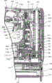
Fig. 1 is the side sectional view that the integral body of the rechargeable ail gun 100 that relates to of expression present embodiment constitutes.
Fig. 2 is based on the cutaway view of the A-A line of the rechargeable ail gun 100 of Fig. 1, and expression hammer 125 is in the state of bottom dead center position.
Fig. 3 is the amplification view of formation at the main position of the rechargeable ail gun 100 in the presentation graphs 1.
Fig. 4 is based on the cutaway view of the A-A line of the rechargeable ail gun 100 of Fig. 1, and expression hammer 125 is in the state of squeezing into standby position.
Fig. 5 is from the ratchet 116 of the anti-locking mechanism of backwards rotation of the reducing gear 115 of squeezing into the observed formation present embodiment of mechanism's 117 sides of Fig. 3 and the figure of sheet spring 118.
Fig. 6 is the ratchet 116 of Fig. 5 and the side view of sheet spring 118.
Fig. 7 is expression present embodiment the energising of drive motor 113 is driven and the figure of the formation of the operating means 160 that energising stops to operate.
Fig. 8 is that the operation stroke that is illustrated in drive operation finishes, and the leading section 171a of cam bit 171 comes to the figure of situation of the anti-locking mechanism of backwards rotation of the state that joins of the blocking surface 178d of cam disc 177.
Fig. 9 is the leading section 171a of expression cam bit 171 and is disengaged the joining of blocking surface 178d of cam disc 177, the figure of the situation of the anti-locking mechanism of the backwards rotation of the disarm state of joining.
Symbol description among the figure:
100 rechargeable ail gun 101 bodies 103 motor cases
105 gear-box 105a first by contacting wall 105b second by contacting wall
106 gaps, 107 handles, 109 battery cases, 111 nail bins
112 injection part 112a nail is squeezed into mouthful 113 drive motors
115 reducing gear 115a output shaft 115b driven wheels
116 ratchets, 1 16a is stuck groove 116b wall 116c inclined wall
117 squeeze into the 118 spring 118a engagings pawl 118b of mechanism, the first butt sheet
The 118c second butt sheet 119 hammer driving mechanisms 121 guide rails 123 saddles
The engaging protrusion of the engaging protrusion 125b bottom on 125 hammer 125a tops
126 blocks, 127 compression helical springs, 129 drivers, 131 connecting pins
The gear of gear 133a axle 134 frameworks 135 bottoms on 133 tops
The dance roller 137a back shaft on 135a axle 137 tops
143 safety poles, 145 lamps 147 are lit a lamp with switch 148 first switches
160 operating means, 161 internal switches, 163 triggers, 171 cam bits
177 cam discs, 178 cam surface 178a hold with both hands with both hands and get tilting zone
The specific embodiment
Below, explain embodiments of the present invention with reference to Fig. 1~Fig. 9.About present embodiment, employing describes as the rechargeable ail gun of an example of " drive in working machine " of the present invention.Fig. 1 is the side sectional view that the integral body of the rechargeable ail gun 100 that relates to of expression present embodiment constitutes, and Fig. 2 is based on the cutaway view of the A-A line of the rechargeable ail gun 100 of Fig. 1.The amplification view of the formation of the major part of the rechargeable ail gun 100 of presentation graphs 1 among Fig. 3.
As shown in Figure 1,, see briefly that its main body formation comprises: the body 101 that forms the shell of rechargeable ail gun 100 about the rechargeable ail gun 100 that present embodiment relates to; The battery case 109 that holds battery; Load the nail bin 111 that the nail of part is squeezed in the conduct that is driven into processed material.
Handle 107 is configured in the top of motor case 103, and gear-box 105 is configured in an end (Fig. 1 right side) of the horizontal direction of this motor case 103 and handle 107, and battery case 109 is configured in the other end of horizontal direction.Nail bin 111 is configured in the below of motor case 103 and gear-box 105.In addition, nail bin 111 constitutes: the bottom of the nail supply gear case 105 that should squeeze into, and promptly at the injection part 112 of the nail that leading section connected of body 101.
As shown in Figure 3, squeezing into mechanism's 117 main bodys formation comprises: extension of linearity ground and upper end and bottom are fixed in the bar-shaped guide rail 121 of gear-box 105 respectively on above-below direction; But be installed in the hammer 125 on the guide rail 121 saddle 123 knee-actions by tubular; Squeeze into action for hammer 125 is done downwards, make bouncing force act on the compression helical spring 127 of this hammer 125; Move and squeeze into the nail that mouthful 112a supplies with hammer 125 and apply hitting power, thus this nail is driven into the driver 129 of processed material to the nail of injection part 112.Hammer 125 is connected by connecting pin 131 with driver 129.In addition, hammer 125 has with the dance roller 137,139 up and down of hammer driving mechanism 119 and engage, and engaging protrusion 125a, 125b above being pushed to.In addition, for convenience's sake, omit the diagram of nail and processed material.
At this, the compression helical spring 127 in the present embodiment is helical springs of a kind of following formation: store bouncing force by shrinking, and to do by the compression helical spring 127 that stores bouncing force and freely to extend action, to discharge bouncing force.This compression helical spring 127 is equivalent to " helical spring " among the present invention.This compression helical spring 127 is also referred to as " compression helical spring ".In addition, hammer 125 in the present embodiment and driver 129, be by storing bouncing force compression helical spring 127 freely extend the action component that the linearity action is done in action, it constitutes " action component " among the present invention.
In the present embodiment, the safety pole 143 that on handle 107, has the drawing operation of forbidding trigger 141.For trigger 141, when safety pole 143 places Fig. 1 with the locked position shown in the solid line, can not carry out the drawing operation, and when safety pole 143 places Fig. 1 with the lock release position shown in the hypothesis line, then can carry out the drawing operation.In addition, body 101 is provided with the lamp 145 (with reference to Fig. 1) of squeezing into the zone of irradiation nail.Constituting of lamp 145: when safety pole 143 is placed in the lock release position, will lights a lamp by this safety pole 143 and to do ON Action with switch 147 and light a lamp, and when safety pole 143 is placed in locked position, will light a lamp to make of switch 147 disconnects action and turns off the light.
The rotation output of drive motor 113 is delivered to hammer driving mechanism 119 by the reducing gear 115 of planetary gear type as rotational motion." driver element " of the present invention is made of these drive motors 113 and hammer driving mechanism 119.As shown in Figures 2 and 3, hammer driving mechanism 119 main bodys formation comprises: the interlock card is incorporated in the upper and lower gear 133,135 as rotor that rotates round about mutually in the vertical plane mutually; Above-mentioned hammer 125 is pushed to the dance roller 137,139 (with reference to Fig. 2) up and down of top along with the rotational action of these gears 133,135.
Gear 133,135 is installed in rotation on the framework 134 that is disposed in the gear-box 105 by axle 133a, 135a.Dance roller the 137, the 139th is installed on from the position of the center of rotation off-centre of gear 133,135 by back shaft 137a, 139a free to rotately, and, promptly do circular-arc motion on every side along with the rotation of gear 133,135 moves in a circle at gear 133,135 centers.In addition, apart from the offset of the back shaft 137a of the dance roller 137 on top, be set to offset and be equal to each other apart from the back shaft 139a of the dance roller 139 of bottom.The gear 135 of bottom engages with driven wheel 115b interlock on the output shaft 115a that is formed on reducing gear 115, and is rotated driving with the speed reducing ratio of regulation.The gear 135 of bottom is set to 1 to 1 with the gear ratio of the gear 133 on top.The dance roller 139 of bottom is set as the configuration with about 180 phase differences of spending with the dance roller 137 on top.And dance roller 137,139 up and down is placed in position farthest, space, and promptly the dance roller 139 of bottom is placed in the position of downside of the gear 135 of bottom, and the dance roller 137 on top is placed in the upside of the gear 133 on top.
When drive motor 113 is energized driving, and when gear up and down 133,135 rotates to the direction of arrow of Fig. 2, the dance roller 139 of bottom engages with the engaging protrusion 125b of the bottom of hammer 125 from the below and moves in a circle upward, this hammer is placed in bottom dead center position shown in Figure 2 (squeezing into the completing place), and pushes hammer 125 to top by the above-below direction composition in this circular motion.The amount of pushing to by 139 pairs of hammers 125 of dance roller of bottom reach maximum near the time, the dance roller 137 on top engages also with the engaging protrusion 125a on the top of hammer 125 from the below and moves in a circle upward, and above hammer 125 pushed to.
Like this, hammer 125 is by the relaying of dance roller 137,139 up and down, and from lower dead center upward, promptly to the top dead centre side shifting, by the shift action upward of this hammer 125, compression helical spring 127 is compressed and bouncing force is stored.Specifically, hammer 125 stops to remain on the standby position of squeezing into shown in Figure 4.Then, the operation of the drawing of the trigger 141 by thereafter, the engaging protrusion 125a on the top of hammer 125, near top dead centre, from the dance roller 137 on top by further to cam 140 handing-over.When driver 129 and hammer 125 together are moved to the top, be seated in the nail that nail in the nail bin 111 is fed into injection part 112 and squeeze into a mouthful 112a, after this, when being disengaged with engaging of this cam 140, hammer 125 is done downwards by the bouncing force of compression helical spring 127 and is squeezed into action.Thus, the nail that supplies to injection part 112 is squeezed into the driver 129 that the nail of mouthful 112a descended and is driven into processed material in this nail is squeezed into mouthful 112a.The hammer of squeezing into after the action 125 is maintained at lower dead center by the butt with block 126.
In above-mentioned reducing gear 115, be equipped with the mechanism that prevents doing backwards rotation in the opposite direction with the side that rotates (forward rotation) by the driving of drive motor 113, promptly so-called " backwards rotation is prevented locking mechanism ".Constitute the ratchet described later 116 of the anti-locking mechanism of this backwards rotation and sheet spring 118 corresponding to " backwards rotation is prevented locking mechanism " among the present invention.The anti-locking mechanism of this backwards rotation of reducing gear 115 as shown in Figure 5 and Figure 6.Fig. 5 is that the backwards rotation of the reducing gear 115 of squeezing into mechanism 117 unilateral observations formation present embodiment of expression from Fig. 3 is prevented the ratchet 116 of locking mechanism and the figure of sheet spring 118, the ratchet 116 among Fig. 6 in the presentation graphs 5 and the side view of sheet spring 118.
As shown in Figure 5 and Figure 6, in the present embodiment, the output shaft 115a of reducing gear 115 is provided with discoid ratchet 116.The Zhou Fangxiang zone of this ratchet 116 (being arranged on the sour jujube face of the outer peripheral portion of ratchet 116) is provided with a plurality of groove 116a that are stuck.Respectively be stuck groove 116a and have the wall 116b that extends at the left and right directions of Fig. 6; The inclined wall 116c that extends from the bottom angled shape ground of this wall 116b.On the other hand, being provided with permission with the opposed position of sour jujube face of ratchet 116 is the tabular sheet spring 118 that rotates at center with output shaft 115a (position that is equivalent to " support portion " of the present invention) relative to ratchet 116.In this sheet spring 118, be provided with engaging pawl 118a, the first butt sheet 118b and the second butt sheet 118c in its outer rim.Engaging pawl 118a is the shape of extending along the direction of the inclined wall 116c that respectively is stuck groove 116a of ratchet 116, and can relatively respectively be stuck groove 116a and push shape ground and engage.And, constitute: engaging pawl 118a be stuck the fastening state that groove 116a engages under, driving by drive motor 113, allow ratchet 116 with respect to the rotation (be also referred to as " forward rotation " or " just change ") of sheet spring 118, but forbid that ratchet 116 is with respect to the rotation (be also referred to as " backwards rotation " or " reverse ") of sheet spring 118 to arrow 12 directions of Fig. 5 in arrow 10 directions of Fig. 5.
Specifically, do forward rotation (when being equivalent to " ratchet is to the rotation of a direction " among the present invention at ratchet 116 with respect to sheet spring 118, the inclined wall 116c that respectively is stuck groove 116a does sliding action with respect to engaging pawl 118a, thereby the groove 116a that is stuck that engaging pawl 118a is engaged switches successively along the Zhou Fangxiang zone of ratchet 116, therefore, allow the forward rotation of ratchet 116.On the other hand, do backwards rotation (when being equivalent to " ratchet rotates to another direction " among the present invention at ratchet 116 with respect to sheet spring 118, engaging pawl 118a and regulation be stuck groove 116a, be that a plurality of 116b of wall arbitrarily that are stuck groove 116a bump and connect, block and end and keep only state of this card thereby be stuck groove 116a, so the backwards rotation of ratchet 116 is under an embargo by this.
In formation shown in Figure 5, record about the center of rotation of sheet spring 118 occasion consistent with the center of rotation of ratchet 116, the center of rotation of sheet spring 118 can be consistent with the position of the center of rotation of ratchet 116, perhaps also can be configured in the position of staggering mutually but in the present invention.In formation shown in Figure 5, record about in each position of ratchet 116, be provided with a plurality of occasions that are stuck groove 116a in the Zhou Fangxiang zone, but in the present invention, also can be equivalent to be stuck the groove that is stuck of groove 116a in the peripheral part setting of the arc surface of ratchet 116, also can replace sheet spring 118 and adopt and have and the corresponding parts that engage pawl of this slot.
But, in driving along with drive motor 113, when ratchet 116 is done forward rotation around output shaft 115a, engaging pawl 118a by fastening state each other and be stuck frictional force between the groove 116a (inclined wall 116c), sheet spring 118 are dragged to produce to the direction identical with ratchet 116 to involve rotation.Adopt following formation in the present embodiment: on sheet spring 118, be provided with can with the first first butt sheet 118b that is connected by contacting wall 105a of gear-box 105 sides.By this formation, sheet spring 118 is that the direction of the arrow 10 among middle mind-set Fig. 5 is rotated with output shaft 115a, at the first butt sheet 118b and first first stop position (solid line position among Fig. 5) that is connected by contacting wall 105a, forbids its continuation forward rotation.First stop position, the first butt sheet 118b of this moment, first is equivalent to " primary importance ", " first abutting part ", " first by abutting part " among the present invention respectively by contacting wall 105a.
On the other hand, backwards rotation about ratchet 116, by engaging pawl 118a and the power that engages that is stuck between the groove 116a, desire under the occasion that the direction identical with ratchet 116 rotated at sheet spring 118, at second second stop position (the hypothesis line position among Fig. 5) that is connected by contacting wall 105b of the second butt sheet 118c and gear-box 105 sides, forbid that it continues backwards rotation.Second stop position, the second butt sheet 118c of this moment, second is equivalent to " second place ", " second abutting part ", " second by abutting part " among the present invention respectively by contacting wall 105b.
In a word, the play (size is the gap 106 of d1 in Fig. 5) that the sheet spring 118 of present embodiment can be by ormal weight rotates between the first butt sheet 118b and first first stop position that is connected by contacting wall 105a and the second butt sheet 118c and second second stop position that is connected by contacting wall 105b action.This gap 106 and gap described later 179 also are known as " gap " or " at interval ".Forbid that thus ratchet 116 relative sheet springs 118 do backwards rotation to arrow 12 directions, but, owing to allow sheet spring 118 itself to do from the backwards rotation of second stop position to first stop position, its result, become one shape and allow backwards rotation of ratchet 116 and sheet spring 118.
Below, the energising of the drive motor 113 of operation present embodiment is driven and the formation of the operating means 160 that energising stops to describe according to Fig. 7.Operating means 160 main bodys formation comprises: the drawing operation by the user entering the trigger 163 of on-state; With the drawing operation interlock of this trigger 163, and enter the internal switch 161 of on-state; Control the on-state thereafter of the internal switch 161 that has entered on-state or the cam disc 177 of off-state.
Trigger 163 main bodys formation comprises: be configured on the handle 107, and carried out the trigger 141 of the drawing operation of linearity by the user; First switch 148 (with reference to Fig. 1 and Fig. 3), it often is the off-state application of force that drives to the energising of forbidding drive motor 113 by force application spring (omission diagram), and enters the on-state of the energising driving that allows drive motor 113 by the drawing operation of trigger 141; Make the drawing operation of trigger 141 and the rocking arm (omitting diagram) of internal switch 161 interlocks.
With cam disc 177 can (with reference to Fig. 3) being installed with the mode of gear 133 unitary rotation on top in the above-mentioned hammer driving mechanism 119.Cam disc 177 is equivalent to " rotor " among the present invention.For cam disc 177, its periphery is set at cam surface 178, be configured to this cam surface 178 the leading section 171a of cam bit 171 opposed.The cam surface 178 of cam disc 177 has on Zhou Fangxiang with lower area: hold with both hands with both hands and get tilting zone 178a, it is fastened on the leading section 171a of the cam bit 171 that moves to the approach axis that makes second switch 173 be in on-state with the drawing operation interlock of trigger 141, and make this cam bit 171 continue to move to approach axis, remove the interlock of cam bit 171 and trigger 141 sides thus; The big regional 178b in footpath, it relatively moves when keeping with the engaging of the leading section 171a of cam bit 171, and keeps the on-state of second switch thus; Path zone 178c, it is removed and the engaging of the leading section 171a of cam bit 171, and allows to return to the off-state of second switch.
Hold with both hands with both hands and get tilting zone 178a between big regional 178b in footpath and path zone 178c, and by forming to the inclined-plane that 178b linearity ground, zone, big footpath extends from path zone 178c.Big regional 178b in footpath and path zone 178c are that the arc surface at center forms by the center of rotation with cam disc 177 respectively.In addition, cam disc 177 has blocking surface 178d on the path zone 178c and the border of getting tilting zone 178a that holds with both hands with both hands, the side of leading section 171a by this blocking surface 178d and cam bit 171 connects (running into), limits the rotation (surmounting) above the assigned position of this cam disc 177.Like this, cam bit 171 is to offset to fetch by the blocking surface 178d by its leading section 171a and cam disc 177 cam disc 177 cards are only being squeezed into the parts of standby position, is equivalent to " latch for printed circuit " among the present invention.In addition, the blocking surface 178d of Ci Shi cam disc 177 is equivalent to " by the fastener " among the present invention.And, constituting of cam disc 177: place holding with both hands with both hands of 178c of path zone to get the position of tilting zone 178a side end the leading section 171a of cam bit 171, promptly connect with blocking surface 178d or approaching set positions for squeezing into standby position, when rotating action, get the order of tilting zone 178a, the big regional 178b in footpath, path zone 178c with respect to cam bit 171 to hold with both hands with both hands and come opposed.
In addition, in the present embodiment, as shown in Figure 7, path zone 178c occupies the scope above the degree of 90 in the circumference of cam disc 177.Be set to following the recovery to the off-state of second switch 173, stop after drive motor 113 energisings, the braking or the inertia operating space that can be used as this drive motor 113 are used.That is, path zone 178c constitutes and comprises braking or inertia operating space.
Above-mentioned drive motor 113 constitutes: being energized driving by trigger 141 directly actuated Motor Drive with first switch 148 with when the Motor Drive of action is switched on action respectively with second switch 173 with the internal switch 161 of the drawing of trigger 141 operation interlock, be disconnected and switch on when any one party of first switch 148 or second switch 173 is disconnected action.After drive motor 113 is energized driving, as mentioned above, drive hammer driving mechanism 119 by reducing gear 115, in the time of hammer driving mechanism 119 compression compression helical spring 127, push hammer 125 to top dead centre from lower dead center.And, after shown in Figure 4 squeezing into is stopped maintenance on the standby position, operate the hammer 125 that reaches top dead centre by the drawing of trigger 141, squeezed into downwards by the bouncing force of compression helical spring 127.In this drive operation that is undertaken by hammer 125, return the action of squeezing into standby position from the standby position of squeezing into shown in Figure 4 via bottom dead center position shown in Figure 2 according to hammer 125, come regulation one-stop operation stroke (being also referred to as " work cycle ").
In addition, as mentioned above, carry out first time by hammer 125 during drive operation, constitute: following closely drive operation finish time for the first time by the second switch 173 of internal switch 161 actions in the operation of the drawing by trigger 141, even keep the drawing operation of trigger 141, also be disconnected always.That is, when following closely drive operation and finish the first time of being undertaken, constantly the energising of drive motor 113 is disconnected,, can not changes over to and follow closely drive operation for the second time even keep the drawing operation of trigger 141 at that by hammer 125.Thus, the secondary that can prevent so-called nail beats.In addition, operate after the drive motor 113 energising drivings by the drawing of trigger 141, when the drawing of having removed trigger 141 previous stage of the nail drive operation that finishes to be undertaken by hammer 125 is operated, do the disconnection action by these trigger 141 directly actuated first switches 148, disconnection is to the energising of drive motor 113, thereby can interrupt the nail drive operation that undertaken by hammer 125.
At this, the effect of the anti-locking mechanism of backwards rotation of above-mentioned reducing gear 115 is described with reference to Fig. 8 and Fig. 9.Expression finishes the operation stroke of drive operation among Fig. 8, and the leading section 171a of cam bit 171 comes to the appearance of preventing locking mechanism against state backwards rotation down of the blocking surface 178d of cam disc 177.The appearance of preventing locking mechanism against backwards rotation that be disengaged, under disarm state of the blocking surface 178d of leading section 171a and the cam disc 177 of expression cam bit 171 among Fig. 9.
As shown in Figure 8, when the operation stroke of drive operation has just finished, the inertia force of forward rotation direction (arrow 30 directions among Fig. 8) acts on the cam disc 177, and the leading section 171a that forms cam bit 171 abut to cam disc 177 blocking surface 178d against state (being also referred to as " butt state ").In addition, act on this inertia force of cam disc 177, transmitted as the rotatory force to arrow 30 directions of the gear 133 on the rotatory force to arrow 20 directions of the gear 135 of the rotatory force of output shaft 115a, bottom, top in order to arrow 10 directions from drive motor 113 sides.On the other hand, when the squeezing into stroke and just finished of this drive operation, sheet spring 118 forms by the relative ratchet 116 of engaging pawl 118a and is stuck the fastening state that groove 116a engages, and forms first state that is connected by contacting wall 105a of the first butt sheet 118b and gear-box 105 sides.Thus, thus prevent that sheet spring 118 is to being dragged the rotation that involves that produces with ratchet 116 equidirectionals.
But, abut to the state of the blocking surface 178d of cam disc 177 at the leading section 171a of cam bit 171, during with this state consistency that ratchet 116 and sheet spring 118 engage, can envision the locking state that the action that will form cam bit 171 is locked.When forming this locking state, though drawing operating trigger 141, the leading section 171a that also can't remove cam bit 171 with respect to blocking surface 178d against, thereby produce the problem that cam bit 171 can't rise.
Therefore, present embodiment constitutes: even be in the blocking surface 178d that the leading section 171a of cam bit 171 abuts to cam disc 177, and the state of ratchet 116 and sheet spring 118 engagings also allows to be in the backwards rotation of the ormal weight of the ratchet 116 of state of mutual engaging and sheet spring 118.Specifically, as mentioned above, sheet spring 118 the first butt sheet 118b and first first stop position that is connected by contacting wall 105a, and the second butt sheet 118c and second second stop position that is connected by contacting wall 105b between, the play (size is the gap 106 of d1 among Fig. 8) by ormal weight can rotate action.At this moment, the bouncing force of compression helical spring 127 acts on the ratchet 116 by reducing gear 115, desires to make ratchet 116 to rotate to the backwards rotation direction.Therefore, transmitted this ratchet 116 of the bouncing force of compression helical spring 127, being stuck groove 116a place engaging pawl 118a and being in the only sheet spring 118 of the state shape that becomes one of card in regulation, only with corresponding with the big or small d1 in gap 106 apart from backwards rotation, rotate when moving to second stop position for 12 directions of the arrow among middle mind-set Fig. 9 with output shaft 115a at sheet spring 118, offseted to fetch by contacting wall 105b by the second butt sheet 118c and second and forbid continuing backwards rotation.
As mentioned above, sheet spring 118 rotating structure between first stop position and second stop position; The structure that is connected by contacting wall 105a at the first butt sheet 118b of the first stop position last slice spring 118 and first; " cancel system " in structure formation the present invention that the second butt sheet 118c and second of the second stop position last slice spring 118 is connected by contacting wall 105b.
At ratchet 116 and sheet spring 118 shape that becomes one, only with in the process apart from backwards rotation corresponding with the big or small d1 in gap 106, cam disc 177 also rotates to the backwards rotation direction, as shown in Figure 9, the leading section 171a of cam bit 171 only leaves the blocking surface 178d predetermined distance (size is the gap 179 of d2) of cam disc 177, forms the state (butt disarm state) that mutual butt is disengaged.That is, the second butt sheet 118c and second by eliminating sheet spring 118 is by the gap between the contacting wall 105b, and the generation size is the gap 179 of d2 between the blocking surface 178d of the leading section 171a of cam bit 171 and cam disc 177 specifically.That is, in the present embodiment, the second butt sheet 118c and second of sheet spring 118 is by the gap between the contacting wall 105b 106, is defined in the amount of spin in the backwards rotation of cam disc 177.
In addition, the rotatory force in this backwards rotation of cam disc 177 is from compression helical spring 127, to the engaging protrusion 125a on the top of hammer 125, transmit successively to the order of the back shaft 137a of the dance roller 137 on top again.Like this, forming size between the blocking surface 178d of the leading section 171a of cam bit 171 and cam disc 177 is the gap 179 of d2, avoid the butt of the shape of nipping of relative blocking surface 178d thus, prevent the action locking of cam bit 171, thereby can successfully carry out the drawing operation of trigger 141.
In addition, the present invention is not limited only to above-mentioned embodiment, can expect various application examples or modification based on present embodiment.For example, also can practice the following mode of present embodiment.
In above-mentioned present embodiment, the mechanism that records the backwards rotation that will allow cam disc 177 is arranged at the occasion with the ratchet 116 of this cam disc 177 interlocks, but in the present invention, also can adopt the mechanism that this cam disc 177 is provided with itself backwards rotation that allows cam disc 177.
In addition, in above-mentioned present embodiment, an example as drive in working machine, with rechargeable ail gun is that example is illustrated, but the present invention is not limited only to rechargeable ail gun, the present invention can be applicable to the formation of the ail gun of AC drive type or pneumatic type, and the formation of the nailing machine of rechargeable, AC drive type, pneumatic type.
Claims (2)
1. drive in working machine is squeezed into the drive operation of part to processed material, and this drive in working machine is characterised in that, comprising:
Helical spring, it can store bouncing force;
Action component, it is installed in above-mentioned helical spring end, and above-mentioned helical springly freely extends the action that linearity is done in action by what store bouncing force, thus the above-mentioned part of squeezing into is applied the power of squeezing into;
Driver element, it overcomes its bouncing force to above-mentioned helical spring and rolls driving to roll up direction;
Rotor, it is accompanied by by what above-mentioned driver element carried out and above-mentioned helical springly rolls driving, overcomes this helical spring bouncing force, to the action that rotates of forward rotation direction;
Latch for printed circuit, it is carrying out rolling of above-mentioned driver element when driving, by with being connected of above-mentioned rotor by fastener, and this rotor card is only being squeezed into standby position, and, after removing this card and ending, will only block once more to this rotor that the forward rotation direction has been rotated a week and squeeze into standby position, stipulate the operation stroke of drive operation thus;
Backwards rotation is prevented locking mechanism, and it allows above-mentioned rotor forward rotation, and forbids backwards rotation;
Cancel system, it is under the driving halted state of above-mentioned driver element (119), only blocked above-mentioned when squeezing into standby position at above-mentioned rotor (133,135) by above-mentioned latch for printed circuit, the backwards rotation of the ormal weight of this rotor that locking mechanism is caused is prevented in permission by above-mentioned backwards rotation, thereby can avoid being connected of above-mentioned rotor by fastener and above-mentioned latch for printed circuit with meshing shape
The anti-locking mechanism of above-mentioned backwards rotation comprises: the tine with engaging pawl; Have a plurality of grooves that are stuck that this engaging pawl can engage in the Zhou Fangxiang zone, and the ratchet that rotates with above-mentioned rotor interlock;
The anti-locking mechanism of above-mentioned backwards rotation constitutes: at above-mentioned ratchet when a direction is rotated, the above-mentioned groove that is stuck by above-mentioned engaging pawl engaging switches successively along above-mentioned Zhou Fangxiang zone, allow the forward rotation of above-mentioned rotor, and, at above-mentioned ratchet when other direction rotates, by being ended, above-mentioned engaging pawl card is stuck groove, the backwards rotation of forbidding above-mentioned rotor in regulation
Above-mentioned cancel system constitutes: at above-mentioned ratchet when direction is rotated, keep the permission of the forward rotation of the above-mentioned rotor that is undertaken by the anti-locking mechanism of above-mentioned backwards rotation, at above-mentioned ratchet when other direction rotates, be in the above-mentioned engaging pawl that is stuck the state that groove engages with afore mentioned rules, keeping under the state of this engaging, with the other direction rotation in the same way of above-mentioned ratchet one, allow the backwards rotation of the ormal weight of above-mentioned rotor thus.
2. drive in working machine according to claim 1 is characterized in that,
Above-mentioned cancel system comprises: the support portion of supporting above-mentioned tine between the primary importance and the second place rotationally; First abutting part of above-mentioned primary importance and above-mentioned tine connect first by abutting part; Second abutting part of said second position and above-mentioned tine connect second by abutting part;
Above-mentioned cancel system constitutes: at above-mentioned ratchet when direction is rotated, keep the permission of the forward rotation of the above-mentioned rotor that is undertaken by the anti-locking mechanism of above-mentioned backwards rotation, and above-mentioned tine is set at above-mentioned primary importance, connected by abutting part by above-mentioned first abutting part and above-mentioned first, and between above-mentioned second abutting part and above-mentioned second is by abutting part, form predetermined gap;
And constitute as follows: at above-mentioned ratchet when other direction rotates, blocked the above-mentioned engaging pawl that is stuck groove that ends at afore mentioned rules, keeping under the state of its engaging, with the other direction rotation in the same way of above-mentioned ratchet one, thereby allow the backwards rotation of above-mentioned rotor, and, in the gap of above-mentioned tine by afore mentioned rules from primary importance after the second place is rotated, connected by abutting part by above-mentioned second abutting part and above-mentioned second, stipulate the amount of spin in the backwards rotation of above-mentioned rotor thus.
Applications Claiming Priority (2)
| Application Number | Priority Date | Filing Date | Title |
|---|---|---|---|
| JP2005314302A JP4708954B2 (en) | 2005-10-28 | 2005-10-28 | Driving tool |
| JP2005314302 | 2005-10-28 |
Publications (2)
| Publication Number | Publication Date |
|---|---|
| CN1954968A CN1954968A (en) | 2007-05-02 |
| CN100462206C true CN100462206C (en) | 2009-02-18 |
Family
ID=38062623
Family Applications (1)
| Application Number | Title | Priority Date | Filing Date |
|---|---|---|---|
| CNB2006101040270A Expired - Fee Related CN100462206C (en) | 2005-10-28 | 2006-07-31 | Drive operation tool |
Country Status (3)
| Country | Link |
|---|---|
| JP (1) | JP4708954B2 (en) |
| CN (1) | CN100462206C (en) |
| TW (1) | TW200716329A (en) |
Families Citing this family (7)
| Publication number | Priority date | Publication date | Assignee | Title |
|---|---|---|---|---|
| JP5382396B2 (en) * | 2007-04-24 | 2014-01-08 | 日立工機株式会社 | Driving machine |
| US7963430B2 (en) * | 2008-10-15 | 2011-06-21 | Chervon Limited | Nailer device |
| DE202009017659U1 (en) * | 2009-12-28 | 2011-05-12 | Illinois Tool Works Inc., Glenview | Drive-in module for driving fasteners |
| CN101992451A (en) * | 2010-09-15 | 2011-03-30 | 苏州卓识商务咨询有限公司 | Electric nailing hammer |
| CN101992447A (en) * | 2010-09-15 | 2011-03-30 | 苏州卓识商务咨询有限公司 | Electric nail hammer |
| CN101992439A (en) * | 2010-09-15 | 2011-03-30 | 苏州卓识商务咨询有限公司 | Electric nail hammer |
| US20220134524A1 (en) * | 2019-03-29 | 2022-05-05 | Koki Holdings Co., Ltd. | Driving tool |
Citations (3)
| Publication number | Priority date | Publication date | Assignee | Title |
|---|---|---|---|---|
| CN2081783U (en) * | 1990-05-04 | 1991-07-31 | 蔡宜雄 | Double-cam transmission structure of electric nailing machine |
| US5174485A (en) * | 1989-12-19 | 1992-12-29 | Duo-Fast Corporation | Fastener driving tool |
| JPH07100306B2 (en) * | 1990-04-18 | 1995-11-01 | 株式会社マキタ | Electric tucker |
Family Cites Families (5)
| Publication number | Priority date | Publication date | Assignee | Title |
|---|---|---|---|---|
| JPS60135182A (en) * | 1983-12-23 | 1985-07-18 | 松下電工株式会社 | Electric cutter |
| JPH0618790Y2 (en) * | 1990-02-28 | 1994-05-18 | レジター・パワー・トゥールズ・カンパニー・リミテッド | Electric nailer |
| JP2568736Y2 (en) * | 1993-12-06 | 1998-04-15 | マックス株式会社 | Portable electric staple driving machine |
| JP2567867Y2 (en) * | 1993-12-15 | 1998-04-08 | マックス株式会社 | Starting device for portable electric staple driving machine |
| JP3520433B2 (en) * | 1996-08-29 | 2004-04-19 | マックス株式会社 | Reverse rotation prevention mechanism of needle feeder in electric stapler |
-
2005
- 2005-10-28 JP JP2005314302A patent/JP4708954B2/en not_active Expired - Fee Related
-
2006
- 2006-07-31 CN CNB2006101040270A patent/CN100462206C/en not_active Expired - Fee Related
- 2006-09-12 TW TW095133714A patent/TW200716329A/en not_active IP Right Cessation
Patent Citations (3)
| Publication number | Priority date | Publication date | Assignee | Title |
|---|---|---|---|---|
| US5174485A (en) * | 1989-12-19 | 1992-12-29 | Duo-Fast Corporation | Fastener driving tool |
| JPH07100306B2 (en) * | 1990-04-18 | 1995-11-01 | 株式会社マキタ | Electric tucker |
| CN2081783U (en) * | 1990-05-04 | 1991-07-31 | 蔡宜雄 | Double-cam transmission structure of electric nailing machine |
Also Published As
| Publication number | Publication date |
|---|---|
| TW200716329A (en) | 2007-05-01 |
| JP2007118140A (en) | 2007-05-17 |
| JP4708954B2 (en) | 2011-06-22 |
| CN1954968A (en) | 2007-05-02 |
| TWI298286B (en) | 2008-07-01 |
Similar Documents
| Publication | Publication Date | Title |
|---|---|---|
| CN100519087C (en) | Driving power tool | |
| CN100462206C (en) | Drive operation tool | |
| CN101622100B (en) | Driving tool | |
| US7165379B1 (en) | Forward-reverse tension mechanism for packing machine | |
| US20070102470A1 (en) | Power tool | |
| JP2003501276A (en) | Spindle lock and chipping mechanism of hammer drill | |
| US20210299836A1 (en) | Driving tool | |
| CN102692859A (en) | Mechanism for selectively stopping the striking mechanism of a timepiece according to the available motor torque | |
| US4460107A (en) | Plural mode multi-column dispensing machine | |
| CN105966660A (en) | Manual strapping machine | |
| US6430982B2 (en) | Coil spring forming and conveying assembly | |
| CN1939671A (en) | Drive in working machine | |
| DE69819256T2 (en) | Arrangement for forming and feeding coil springs | |
| US2094185A (en) | Hammer attachment for drills | |
| US3057514A (en) | Mechanism for handling workpieces | |
| CN205033273U (en) | Lift type plastic bottle cuts strip machine | |
| US20030066326A1 (en) | Thread-rolling machine with rotatable rolling plates | |
| CN204826819U (en) | Parking stall lock with with vehicle dead weight energy storage function of exerting pressure | |
| KR0157218B1 (en) | Vending machine | |
| DE1298754B (en) | Self-seller | |
| CN209374396U (en) | A kind of fuse cabinet booster | |
| JPS6354464B2 (en) | ||
| CN201080573Y (en) | Bias strip machine tray modified structure | |
| JP3128452U (en) | Chain with protrusion | |
| CN201078564Y (en) | Rigidity high performance safety clutch |
Legal Events
| Date | Code | Title | Description |
|---|---|---|---|
| C06 | Publication | ||
| PB01 | Publication | ||
| C10 | Entry into substantive examination | ||
| SE01 | Entry into force of request for substantive examination | ||
| C14 | Grant of patent or utility model | ||
| GR01 | Patent grant | ||
| C17 | Cessation of patent right | ||
| CF01 | Termination of patent right due to non-payment of annual fee |
Granted publication date: 20090218 Termination date: 20130731 |