CN100457013C - Filter housing - Google Patents
Filter housing Download PDFInfo
- Publication number
- CN100457013C CN100457013C CNB038036657A CN03803665A CN100457013C CN 100457013 C CN100457013 C CN 100457013C CN B038036657 A CNB038036657 A CN B038036657A CN 03803665 A CN03803665 A CN 03803665A CN 100457013 C CN100457013 C CN 100457013C
- Authority
- CN
- China
- Prior art keywords
- filter
- air
- blade
- flow
- pipeline
- Prior art date
- Legal status (The legal status is an assumption and is not a legal conclusion. Google has not performed a legal analysis and makes no representation as to the accuracy of the status listed.)
- Expired - Fee Related
Links
Images


Classifications
-
- A—HUMAN NECESSITIES
- A47—FURNITURE; DOMESTIC ARTICLES OR APPLIANCES; COFFEE MILLS; SPICE MILLS; SUCTION CLEANERS IN GENERAL
- A47L—DOMESTIC WASHING OR CLEANING; SUCTION CLEANERS IN GENERAL
- A47L9/00—Details or accessories of suction cleaners, e.g. mechanical means for controlling the suction or for effecting pulsating action; Storing devices specially adapted to suction cleaners or parts thereof; Carrying-vehicles specially adapted for suction cleaners
- A47L9/10—Filters; Dust separators; Dust removal; Automatic exchange of filters
- A47L9/12—Dry filters
- A47L9/122—Dry filters flat
-
- A—HUMAN NECESSITIES
- A47—FURNITURE; DOMESTIC ARTICLES OR APPLIANCES; COFFEE MILLS; SPICE MILLS; SUCTION CLEANERS IN GENERAL
- A47L—DOMESTIC WASHING OR CLEANING; SUCTION CLEANERS IN GENERAL
- A47L9/00—Details or accessories of suction cleaners, e.g. mechanical means for controlling the suction or for effecting pulsating action; Storing devices specially adapted to suction cleaners or parts thereof; Carrying-vehicles specially adapted for suction cleaners
- A47L9/0081—Means for exhaust-air diffusion; Means for sound or vibration damping
-
- Y—GENERAL TAGGING OF NEW TECHNOLOGICAL DEVELOPMENTS; GENERAL TAGGING OF CROSS-SECTIONAL TECHNOLOGIES SPANNING OVER SEVERAL SECTIONS OF THE IPC; TECHNICAL SUBJECTS COVERED BY FORMER USPC CROSS-REFERENCE ART COLLECTIONS [XRACs] AND DIGESTS
- Y10—TECHNICAL SUBJECTS COVERED BY FORMER USPC
- Y10S—TECHNICAL SUBJECTS COVERED BY FORMER USPC CROSS-REFERENCE ART COLLECTIONS [XRACs] AND DIGESTS
- Y10S55/00—Gas separation
- Y10S55/03—Vacuum cleaner
Abstract
A filter housing (60) comprises an inlet for receiving airflow, a cavity for receiving a filter (70) and an airflow passage between the inlet and the filter (70). At least one vane (65a, 65b, 65c) is positioned in the airflow passage for partitioning the airflow passage into a plurality of ducts (51, 52, 53). Each vane (65a, 65b) has a non-linear shape in the direction of flow through the airflow passage. This helps to reduce acoustic emissions from the machine since sound waves emitted by the fan and/or motor are caused to bounce off the vanes (65a, 65b), which allows the vanes (65a, 65b) to absorb some of the sound energy. The filter housing (60) can form part of a vacuum cleaner.
Description
Technical field
The present invention relates to a kind of filter housing.Particularly but not exclusively say, the present invention relates to a kind of filter housing that is used on the household electrical appliance such as vacuum cleaner for example.
Background technology
Vacuum cleaner need separate dirt and dust from air-flow.Via engaging the cleaner head with the floor or being connected to flexible pipe and the instrument of bar assembly end, the air of band dirt and dust is inhaled in this electrical equipment.Foul atmosphere is through certain separation equipment, and this separation equipment makes great efforts dirt is separated from air-flow with dust.Many vacuum cleaners suck through the porous sack or blow out this foul atmosphere, thereby dirt and dust are remained in this sack, simultaneously clean air are discharged in the surrounding air.In other vacuum cleaner, cyclone or cyclone are used for from this air-flow dirt and dust being screwed out (for example, referring to EP0042723).No matter be to use which kind of separator, all have small amount of dust to pass separator usually and be carried to fan and electric motor units in, wherein fan and electric motor units are used for producing in operation the air-flow through vacuum cleaner.In addition, the majority of vacuum cleaner fan is by the motor-driven that has carbon brush, and this motor is alternating current series motor for example, and this motor sends carbon particle, and these carbon particles are carried with the air stream of discharge.
In view of this, filter being arranged on motor back and air is very common from the front of this machine discharge point.This filter often is called " behind the motor " filter.
The emission problem arouses attention in the consumer just day by day, and this especially is a problem for asthmatic patient.Therefore, in the recent vacuum cleaner type filter that has than the big filter material surface area is housed, this filter often comprises several types of filter material and foam spacer simultaneously.This filter is very heavy actually, and is quite difficult in cleaner this filter hood simultaneously.In a kind of vacuum cleaner that is called DysonDC05 by Dyson Co., Ltd produce and market, circular rear motor filter be placed on dirt collection bin below.Air-flow towards the filter ground floor passes this filter, and discharges via one group of hole on the filter upper cover from this machine.
A kind of vacuum cleaner discharge filter has been shown in the 5th, 961,677 United States Patent (USP)s, and wherein air flows out from central tube via a series of openings that are formed between the dihedral vane passing open space through before around the cartridge filter around the central tube.
Summary of the invention
The present invention manages to provide a kind of improved filter housing.
Also wish to increase flow rate through the vacuum cleaner air.The ability that high flow velocities makes this cleaner pick up material from a surface usually strengthens with cyclone separator separates goods and materials from this dirty air-flow ability.Yet the air-flow of advancing the speed can make machine that noise is arranged in operation.Possible is to place sound absorptive material on the path of discharged air, but can increase like this because the path resistance that air-flow brings.Like this except gain in weight and machine cost, also to through having a negative impact on the whole speed of air-flow of this machine.
Therefore, the invention provides a kind of filter housing, this filter housing comprises that one is used to admit the cavity of the inlet of air-flow, an admittance filter, gas channel and at least one blade between this inlet and this cavity, this filter has filter surfaces, this blade is arranged in this gas channel, is used for this gas channel is separated into a plurality of slender pipelines.Wherein each blade has a nonlinear shape flowing through on this duct orientation, and this channel direction is along this pipeline basically.Wherein when this filter was installed in the enclosure, an edge that is dimensioned to this blade of each blade was positioned near this filter surfaces or with this filter surfaces and contacts, thereby each pipeline is communicated with the unitary part of this filter surfaces.
Because the sound wave that is sent by fan and/or motor can reflect from blade, therefore, this nonlinear blade is used for reducing the sound wave emission from this machine, makes this blade absorb some acoustic energy like this.Therefore, not adopting special-purpose noise to reduce under the structure situation, realized the noise reduction.
The present invention also provides a kind of electrical equipment, comprises an inlet, filter housing recited above, an Exhaust assembly and produces the device of this electrical equipment of process from the air-flow of this this Exhaust assembly that enters the mouth.
Although the present invention is described with regard to a kind of cylinder (jar) vacuum cleaner, it should be apparent that the present invention can be used for vacuum cleaner, the household electrical appliance of other kind or uses in the machine of certain filter.
Description of drawings
Below with reference to accompanying drawing inventive embodiment is described, wherein:
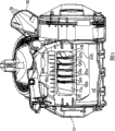
Fig. 1 is the perspective view of vacuum cleaner, wherein is equipped with the filter housing according to invention;
Fig. 2 and 3 is the side view of vacuum cleaner among Fig. 1, wherein shows some inner bodies of this cleaner;
Fig. 4 shows the filter housing of vacuum cleaner among Fig. 1 to 3;
Fig. 5 shows the base of vacuum cleaner and leads to the pipeline of Fig. 4 filter housing;
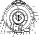
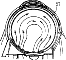
Fig. 6 is the plane of the bottom of Fig. 4 middle filtrator shell;
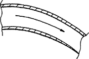
Fig. 7 and 8 shows the effect of blade vortex in reducing air-flow;
Fig. 9 and 10 shows the effect at the blade shape of Fig. 6 middle filtrator shell; And
Figure 11 is the plane of a selectivity embodiment of filter housing bottom.
The specific embodiment
Fig. 1 to 3 shows the example that wherein is equipped with vacuum cleaner 10 of the present invention.This vacuum cleaner 10 is the vacuum cleaner of a kind of cylinder or jar shape type, comprises a base 12 with wheel 13,15, and this wheel is used to make base 12 through wanting the clean surface to move.This base 12 supports a chamber 20, and this chamber 20 is used as the gatherer of parting material simultaneously as the separator that dirt, dust and other chips are separated from air-flow.Although cyclone separator shown here, this separator can adopt any form, and this is inessential for the present invention.Chamber 20 can be dismantled from this base 12, thereby the user can empty this chamber 20.What for the sake of clarity do not illustrate is, flexible pipe is connected on the vacuum cleaner inlet 14, and the user can be installed to a bar or instrument the end of this flexible pipe, is used to clean different surfaces.
Fig. 2 and 3 shows some inner bodies of vacuum cleaner 10 among Fig. 1.This chamber 20 is communicated with this inlet 14, and air-flow can tangential manner enter in this chamber.This chamber 20 has a porose covering 21 that inside center is installed.Zone 22 in covering 21 outsides has formed first cyclonic separation.Hole 23 at this covering 21 is communicated with second cyclonic separation, and wherein this second cyclonic separation comprises the truncated cone separator 25 that a cover is arranged in parallel.The outlet of second level separator 25 is connected to this pre-motor filter 30 on the shell that is used for pre-motor filter 30 via a pipeline 29 and is used for catching any fine dust or the particulate that is not separated by two cyclonic separation 22,25.The downstream of pre-motor filter 30 is communicated with fan and motor housing 48.This shell 48 holds an impeller 45 that is driven by motor 40.The outlet of shell 48 is communicated with filter housing 60 via hole 50.This filter housing 60 holds a pre-motor filter 70, and this filter 70 is used for catching any carbon particle that is trapped in the particle in the air-flow and penetrates from this motor 40.The downstream of this filter housing 60 is communicated with a blast pipe 90, and wherein this blast pipe 90 has outlet opening 95 in its distal end.
Below with reference to Fig. 4 this filter housing 60 is described.This filter housing 60 comprises a bottom 61 and a top 62, and wherein in the present embodiment, bottom 61 has constituted the part of the base 12 of vacuum cleaner 10.This top 62 is releasably attached on the bottom 61 by means of lug 64 and a snap-fastener 67.Certainly, also can use the securing member of other types.This bottom 61 defines a gas channel, and this gas channel is communicated with the hole 50 that forms shell 48 outlets at its upstream extremity.Space between this bottom 61 and this top 62 defines one and is used for filter 70 is contained in wherein cavity.This top 62 has an exhaust branch pipe 63, and this exhaust branch pipe 63 cooperates with these blast pipe 90 lower ends with air tight manner.
A plurality of blade 65a, 65b, 65c are positioned at this gas channel.Two blade 65a, 65b wherein 50 stretch out and enter into the gas channel zone from the hole, and wherein this zone is positioned near the cavity, is used to admit this filter 70.In this zone, this blade 65a, 65b 61 stretch out towards top from the bottom, thereby make them be positioned near the filter 70 and even be in contact with it.The 3rd blade 65c 50 stretches out towards the gas channel zone from the hole, and wherein this zone is positioned near the cavity, is used to admit this filter 70, but stops before described zone.Three separating pipes 51,52,53 are formed between this blade 65a, 65b, the 65c.
This blade 65a, 65b, 65c are used for air-flow being directed to filter 70 through this vacuum cleaner 10 and flowing out from this filter.This blade 65a, 65b, 65c stretch out along parts 61 bottom surfaces from the outlet 50 of motor housing 48.This blade 65a, 65b continuity below the zone of filter 70 is set.This blade 65a, 65b, 65c have two purposes: the first, and they are used for the air-flow that passes filter 70 surfaces is distributed in the uniform mode of appropriateness; The second, their non-linear shape is used for to the sound attenuating from impeller 45.Referring to Fig. 5, this blade 65a, 65b, 65c are divided into six hole 51a, 51b, 52a, 52b, 53a, 53b to outlet 50.Make air stream be divided into six independent air-flows during use like this from impeller 45.Each hole 51a, 51b, 52a, 52b, 53a, 53b form an inlet one of in pipeline 51,52 and 53.Each pipeline 51,52,53 is communicated with one of filter 70 surface areas different and independent part.In the time of in this filter is assemblied in this filter housing 60, the height of each blade 65a, 65b is chosen to its distal edge and is positioned at filter 70 near surfaces, preferably contacts with this surface.Therefore, an independent and different part of each pipeline 51,52,53 and filter 70 is communicated with, and flows through thereby make to be constrained to through filter 70 appropriate sections along the air-flow of each pipeline 51,52,53.
Refer again to Fig. 2, what can find out is that during use, the upstream face of this filter 70 becomes an acute angle (about 10 degree) with respect to the air-flow that enters from this motor housing 48.In the mode just described air-flow is divided into the air-flow that unitary part helps to pass these filter 70 surfaces and distributes equably, arrange for even distribution it is not very desirable even filter 70 enters air-flow with respect to this.Useful especially is the part of the filter surfaces of each pipeline 51,52,53 supply and inlet 50 different distance; Be pipeline 51 supply filters 70 away from part, the forefield of pipeline 52 supply mid portions and pipeline 53 supply filter surfaces 70.
Fig. 6 shows the bottom 61 of this filter housing 60 from the plane.Show the path of taking by arrow 85, also show the path of sound wave process simultaneously by arrow 86 along a part of air-flow of pipeline 52.Because the shape that blade 65a 65b has can be found out, in many places, this sound wave is forced to reflection between blade 65a, 65b, perhaps be at least from these motor housing 48 emitting sound wave a barrier is provided.Blade 65a, 65b, 65c can be molded or also can with bottom 61 whole formation of this filter housing 60, perhaps they can be used as a separate part or cover parts provide, wherein these parts are positioned at this bottom 61 of this filter housing 60.
Provide as mentioned above blade 65a, 65b, 65c useful especially in addition be that this air flow inlet 50 is with respect to this filter housing 60 eccentric settings.Fig. 7 shows does not have this blade to have the air-flow of expecting under the situation.Air enters this filter housing 60 and centers on this shell vortex.This eddy airstream can cause additional noise and may further reduce the absorption ability.Fig. 8 shows blade 65a, 65b is arranged on effect in this filter housing 60.The air that enters this filter housing 60 can not arrive any significant degree by vortex at this moment.
The shape of this blade 65a, 65b, 65c guaranteed between direction and section change smooth transition, this helps avoid " interruption " and the eddy current that increases noise and back pressure.Owing to reduce the absorption ability, therefore desirable especially is to make the back pressure minimum in vacuum cleaner.Fig. 9 and 10 shows the effect by " interruption " air-flow that the very violent pipeline (Figure 10) of a level and smooth curved tube (Fig. 9) and a bending is contrasted.
This blade 65a, 65b, the 65c position in this outlet opening 50 of this motor housing 48 are chosen to like this, and the cross-sectional area of each pipeline 51,52,53 that promptly enters the mouth roughly is directly proportional with the filter part surface area of the suitable supply of those pipes.This helps to guarantee that this air-flow is evenly distributed on the filter surfaces.Supplying with two inlets inlet 51a, the 51b of pipeline 51 (promptly to) for each pipeline helps balance to flow to the air-flow of this filter in addition.
Figure 11 is the plane of a selectivity embodiment of filter housing 60 bottoms 61.In the present embodiment, one group of blade 165a-165e is provided with in the mode different with mode shown in Figure 6.Here, bottom 61 farthest sides of this blade 165a-165e from the outlet opening 50 of motor housing 48 towards filter housing 60 stretch out.As previously mentioned, this layout of blade is divided into a plurality of pipeline 151-156 to these filter 70 following zones, each pipeline is communicated with each blade and has nonlinear, a circuitous shape with this filter surfaces different piece, this has increased the possibility of at least one collision in sound wave and this blade.During use, enter air-flow and will be divided into a plurality of independent parts, each part flows along corresponding pipeline.As previously mentioned, the cross section of each inlet is with in direct ratio by the filter area of this inlet supply.
The operation of this vacuum cleaner is described below.During use, air is extracted by motor-driven impeller 45, enters in the vacuum cleaner 10 through any floor tool and flexible pipe.This foul atmosphere is through this cyclonic separation 22,25, and in this process, in the mode of putting down in writing in the document elsewhere, dirt and dust are removed from this air-flow.Air is from the outlet of cyclone 25, along pipeline 29, flow through pre-motor filter 30, and enters into this motor housing 48.The air of discharging is blown to this hole 50, and passes through preceding fate or six parts of this blade 65a, 65b, 65c there.The separated part of this air-flow flows along these three pipelines 51,52,52,53.As mentioned above, sound wave is reflecting along this pipeline 51,52,53 between blade 65a, 65b, the 65c relatively.Pass through the part of each corresponding pipeline 5152,53 connection of this post-motor filter 70 then from the air-flow of this pipeline 51,52,53.Behind this filter 70 of process, air enters into blast pipe 90 by this inlet.Some air are discharged into (arrow 82 in referring to Fig. 3) in the atmosphere via the end face hole 80 at these filter housing parts 62.Remaining air flows along this discharge duct 90.When air when this blast pipe 90 flows because this pipeline 90 broadens towards flow direction, so this air slows down mobile.This air is discharged into (referring to arrow among Fig. 3 85) in the atmosphere via hole 95.
Claims (7)
1. filter housing, comprise that one is used to admit the cavity of the inlet of air-flow, an admittance filter, gas channel and at least one blade between this inlet and cavity, wherein this filter has filter surfaces, and this blade is arranged on and is used in this gas channel this gas channel is separated into a plurality of slender pipelines; Each blade is crossed in this air flow stream has a nonlinear shape on the gas channel direction, this channel direction is along this pipeline basically; Wherein when this filter was installed in the enclosure, an edge that is dimensioned to this blade of each blade was positioned near this filter surfaces or with this filter surfaces and contacts, thereby each pipeline is communicated with the unitary part of this filter surfaces.
2. filter housing according to claim 1, wherein each blade is an arcuate shape along its whole length.
3. according to claim 1 or 2 described filter housings, at least one has two inlets that are used to admit this air-flow in the wherein said pipeline.
4. filter housing according to claim 1, the cross-sectional area that wherein leads to the inlet of each pipeline roughly is directly proportional with the surface area of the filter part that is communicated with described pipeline.
5. filter housing according to claim 1, wherein this filter surfaces is different with this inlet distance with the part that each pipeline is communicated with.
6. an electrical equipment comprises an inlet, filter housing according to claim 1, an Exhaust assembly and produces the device of this electrical equipment of process from the air-flow of this this Exhaust assembly that enters the mouth.
7. electrical equipment according to claim 6, it is the vacuum cleaner form, this vacuum cleaner also comprises the device that dirt and dust are separated from this air-flow.
Applications Claiming Priority (2)
| Application Number | Priority Date | Filing Date | Title |
|---|---|---|---|
| GBGB0203150.8A GB0203150D0 (en) | 2002-02-11 | 2002-02-11 | A filter housing |
| GB0203150.8 | 2002-02-11 |
Publications (2)
| Publication Number | Publication Date |
|---|---|
| CN1630483A CN1630483A (en) | 2005-06-22 |
| CN100457013C true CN100457013C (en) | 2009-02-04 |
Family
ID=9930809
Family Applications (2)
| Application Number | Title | Priority Date | Filing Date |
|---|---|---|---|
| CNB038036673A Expired - Fee Related CN1323632C (en) | 2002-02-11 | 2003-02-03 | Filter housing |
| CNB038036657A Expired - Fee Related CN100457013C (en) | 2002-02-11 | 2003-02-03 | Filter housing |
Family Applications Before (1)
| Application Number | Title | Priority Date | Filing Date |
|---|---|---|---|
| CNB038036673A Expired - Fee Related CN1323632C (en) | 2002-02-11 | 2003-02-03 | Filter housing |
Country Status (12)
| Country | Link |
|---|---|
| US (2) | US7258714B2 (en) |
| EP (2) | EP1474027B1 (en) |
| JP (3) | JP4515095B2 (en) |
| CN (2) | CN1323632C (en) |
| AT (2) | ATE417538T1 (en) |
| AU (2) | AU2003245673B2 (en) |
| CA (2) | CA2475676C (en) |
| DE (2) | DE60325335D1 (en) |
| ES (1) | ES2276085T3 (en) |
| GB (1) | GB0203150D0 (en) |
| MY (2) | MY135775A (en) |
| WO (2) | WO2003068043A1 (en) |
Families Citing this family (47)
| Publication number | Priority date | Publication date | Assignee | Title |
|---|---|---|---|---|
| US6858080B2 (en) * | 1998-05-15 | 2005-02-22 | Apollo Diamond, Inc. | Tunable CVD diamond structures |
| US6582513B1 (en) * | 1998-05-15 | 2003-06-24 | Apollo Diamond, Inc. | System and method for producing synthetic diamond |
| GB0203150D0 (en) * | 2002-02-11 | 2002-03-27 | Dyson Ltd | A filter housing |
| US7555808B2 (en) | 2004-11-16 | 2009-07-07 | Samsung Gwangju Electronics Co., Ltd. | Vacuum cleaner having a cyclone dust collecting apparatus |
| US7803207B2 (en) * | 2006-03-10 | 2010-09-28 | G.B.D. Corp. | Vacuum cleaner with a divider |
| KR100787062B1 (en) | 2006-06-30 | 2007-12-21 | 주식회사 대우일렉트로닉스 | Vacuum cleaner having filter device |
| US20080276413A1 (en) * | 2007-03-06 | 2008-11-13 | Kurt Clarence Adelman | Integral Vacuum Fan Housing |
| DE102007046553A1 (en) * | 2007-09-28 | 2009-04-09 | BSH Bosch und Siemens Hausgeräte GmbH | Floor care appliance, in particular household vacuum cleaner |
| US7963425B2 (en) * | 2007-12-13 | 2011-06-21 | The Clorox Company | Shrink sleeve for pump dispenser |
| GB2465780B (en) * | 2008-11-28 | 2012-05-16 | Dyson Technology Ltd | Cleaning appliance with pre- and post filter arrangement |
| US9089248B2 (en) * | 2009-02-16 | 2015-07-28 | Samsung Electronics Co., Ltd. | Fan motor apparatus having diffuser unit for vacuum cleaner |
| JP5455486B2 (en) * | 2009-07-22 | 2014-03-26 | 日立アプライアンス株式会社 | Electric vacuum cleaner |
| DE102011007212B4 (en) | 2011-04-12 | 2020-04-23 | BSH Hausgeräte GmbH | Vacuum cleaner with divided air flow channel |
| JP5786441B2 (en) * | 2011-05-13 | 2015-09-30 | 三菱電機株式会社 | Electric vacuum cleaner |
| JP5000011B2 (en) * | 2011-12-27 | 2012-08-15 | シャープ株式会社 | Electric vacuum cleaner |
| GB2503254B (en) * | 2012-06-20 | 2014-12-17 | Dyson Technology Ltd | A cleaning appliance |
| GB2503251C (en) | 2012-06-20 | 2015-07-15 | Dyson Technology Ltd | A self righting cleaning appliance |
| GB2503255B (en) * | 2012-06-20 | 2014-10-15 | Dyson Technology Ltd | A cleaning appliance |
| GB2503257B (en) * | 2012-06-20 | 2014-12-17 | Dyson Technology Ltd | A cleaning appliance |
| GB2503256B (en) * | 2012-06-20 | 2014-10-15 | Dyson Technology Ltd | A cleaning appliance |
| GB2503253B (en) | 2012-06-20 | 2014-10-15 | Dyson Technology Ltd | A cleaning appliance |
| GB2503252B (en) | 2012-06-20 | 2014-12-17 | Dyson Technology Ltd | A self righting cleaning appliance |
| GB2503670B (en) | 2012-07-03 | 2014-12-10 | Dyson Technology Ltd | Method of preheating a brushless motor |
| GB2503671B (en) | 2012-07-03 | 2014-12-17 | Dyson Technology Ltd | Control of a brushless motor |
| JP5903544B2 (en) * | 2012-09-25 | 2016-04-13 | パナソニックIpマネジメント株式会社 | Electric vacuum cleaner |
| CN104736033B (en) | 2013-04-22 | 2017-07-14 | 创科地板护理技术有限公司 | The filter housings of vacuum cleaner |
| JP5841563B2 (en) * | 2013-05-17 | 2016-01-13 | シャープ株式会社 | Electric vacuum cleaner |
| US20140360362A1 (en) * | 2013-06-06 | 2014-12-11 | General Electric Company | Method and systems for particle separation in an exhaust gas recirculation system |
| USD767220S1 (en) | 2013-12-20 | 2016-09-20 | Dyson Technology Limited | Part of a vacuum cleaner |
| USD767219S1 (en) | 2013-12-20 | 2016-09-20 | Dyson Technology Limited | Part of a vacuum cleaner |
| JP5789682B2 (en) * | 2014-01-06 | 2015-10-07 | 日立アプライアンス株式会社 | Electric vacuum cleaner |
| KR20160079277A (en) * | 2014-12-26 | 2016-07-06 | 삼성전자주식회사 | Vacuum cleaner and control method for the same |
| EP3276268B1 (en) | 2016-02-26 | 2019-03-06 | LG Electronics Inc. | Air cleaner |
| EP3211343B1 (en) | 2016-02-26 | 2020-09-09 | LG Electronics Inc. | Air cleaner |
| US10518205B2 (en) | 2016-02-26 | 2019-12-31 | Lg Electronics Inc. | Air cleaner |
| CN111156622B (en) | 2016-02-26 | 2022-04-26 | Lg电子株式会社 | Air cleaner |
| US10436469B2 (en) | 2016-02-26 | 2019-10-08 | Lg Electronics Inc. | Air cleaner |
| CN111765554B (en) | 2016-02-26 | 2022-02-25 | Lg电子株式会社 | Air cleaner |
| EP3211337B1 (en) | 2016-02-26 | 2020-09-23 | LG Electronics Inc. | Air cleaner |
| US9950289B2 (en) | 2016-02-26 | 2018-04-24 | Lg Electronics Inc. | Air cleaner |
| GB2548574B (en) | 2016-03-21 | 2018-04-04 | Dyson Technology Ltd | Vacuum cleaner having a filter assembly |
| US10646806B2 (en) | 2016-03-31 | 2020-05-12 | Lg Electronics Inc. | Cleaner |
| EP3238592B1 (en) | 2016-04-27 | 2021-06-02 | Diversey, Inc. | Vacuum cleaner |
| DE102017208966B4 (en) | 2017-05-29 | 2021-04-29 | BSH Hausgeräte GmbH | Filter arrangement with a flat filter |
| GB2569569B (en) | 2017-12-20 | 2021-04-21 | Dyson Technology Ltd | A filter assembly |
| KR102431691B1 (en) * | 2018-01-29 | 2022-08-11 | 엘지전자 주식회사 | Cleaner |
| CH718415A1 (en) | 2021-03-09 | 2022-09-15 | Mft Dhorlogerie Audemars Piguet Sa | Timepiece comprising a moiré effect display. |
Citations (6)
| Publication number | Priority date | Publication date | Assignee | Title |
|---|---|---|---|---|
| JPS61179121A (en) * | 1985-02-01 | 1986-08-11 | 株式会社日立製作所 | Electric cleaner |
| DE3815321A1 (en) * | 1988-05-05 | 1989-11-16 | Licentia Gmbh | Vacuum cleaner |
| JPH053843A (en) * | 1991-06-28 | 1993-01-14 | Sharp Corp | Cleaner |
| EP0636337A1 (en) * | 1993-07-27 | 1995-02-01 | AEG Hausgeräte GmbH | Vacuum cleaner filter |
| DE19903734A1 (en) * | 1999-01-30 | 2000-08-10 | Aeg Hausgeraete Gmbh | Apparatus for cleaning rooms, especially vacuum cleaner has part of legs of separate mesh in region of air outlet with flow surface offering very low flow resistance |
| CN1312048A (en) * | 2000-03-06 | 2001-09-12 | 胡佛公司 | Dirt-collection system of cleaner |
Family Cites Families (17)
| Publication number | Priority date | Publication date | Assignee | Title |
|---|---|---|---|---|
| US2607437A (en) * | 1948-03-29 | 1952-08-19 | Garrett Corp | Apparatus for separating liquids and gases |
| DE1453072A1 (en) | 1963-06-19 | 1969-01-02 | Siemens Elektrogeraete Gmbh | vacuum cleaner |
| JPS5134572A (en) | 1974-09-18 | 1976-03-24 | Matsushita Electric Ind Co Ltd | SHINKUSOJIKI |
| US4195969A (en) * | 1978-01-05 | 1980-04-01 | Clarke-Gravely Corporation | Vacuum cleaner |
| US4403371A (en) * | 1980-05-07 | 1983-09-13 | Komatsu Zenoah Co. | Debris collecting device |
| EP0042723B1 (en) | 1980-06-19 | 1985-08-21 | Rotork Appliances Limited | Vacuum cleaning appliance |
| JPH02128733A (en) | 1988-11-10 | 1990-05-17 | Sanyo Electric Co Ltd | Vacuum cleaner |
| JP3047984B2 (en) * | 1990-04-18 | 2000-06-05 | 株式会社日立製作所 | Electric vacuum cleaner |
| JPH06317A (en) | 1992-06-23 | 1994-01-11 | Canon Inc | Image forming device and ozone filter and production of ozone filter |
| CN2260563Y (en) * | 1995-10-24 | 1997-08-27 | 周万龙 | Dust-collector with separated system exhausting and cooling exhausting |
| US5946771A (en) * | 1997-01-09 | 1999-09-07 | The Hoover Company | Vacuum cleaner air exhaust arrangement |
| US5961676A (en) * | 1997-06-09 | 1999-10-05 | The Hoover Company | Hard bag door with air directing arrangement |
| US5961677A (en) * | 1998-03-20 | 1999-10-05 | Quality Products, Inc. | Vacuum cleaner exhaust filter |
| GB0203150D0 (en) * | 2002-02-11 | 2002-03-27 | Dyson Ltd | A filter housing |
| US6712869B2 (en) * | 2002-02-27 | 2004-03-30 | Fleetguard, Inc. | Exhaust aftertreatment device with flow diffuser |
| GB2392827B (en) * | 2002-09-14 | 2006-02-01 | Dyson Ltd | A cleaning appliance with wand storgae means |
| US7261762B2 (en) * | 2004-05-06 | 2007-08-28 | Carrier Corporation | Technique for detecting and predicting air filter condition |
-
2002
- 2002-02-11 GB GBGB0203150.8A patent/GB0203150D0/en not_active Ceased
-
2003
- 2003-02-03 US US10/504,057 patent/US7258714B2/en not_active Expired - Fee Related
- 2003-02-03 JP JP2003567233A patent/JP4515095B2/en not_active Expired - Fee Related
- 2003-02-03 EP EP03701622A patent/EP1474027B1/en not_active Expired - Lifetime
- 2003-02-03 CN CNB038036673A patent/CN1323632C/en not_active Expired - Fee Related
- 2003-02-03 DE DE60325335T patent/DE60325335D1/en not_active Expired - Lifetime
- 2003-02-03 EP EP03739542A patent/EP1474025B1/en not_active Expired - Lifetime
- 2003-02-03 AT AT03701622T patent/ATE417538T1/en not_active IP Right Cessation
- 2003-02-03 CA CA2475676A patent/CA2475676C/en not_active Expired - Fee Related
- 2003-02-03 WO PCT/GB2003/000452 patent/WO2003068043A1/en active Application Filing
- 2003-02-03 DE DE60310033T patent/DE60310033T2/en not_active Expired - Lifetime
- 2003-02-03 CN CNB038036657A patent/CN100457013C/en not_active Expired - Fee Related
- 2003-02-03 US US10/504,056 patent/US7721385B2/en not_active Expired - Fee Related
- 2003-02-03 AT AT03739542T patent/ATE346537T1/en not_active IP Right Cessation
- 2003-02-03 WO PCT/GB2003/000437 patent/WO2003068041A1/en active IP Right Grant
- 2003-02-03 AU AU2003245673A patent/AU2003245673B2/en not_active Ceased
- 2003-02-03 CA CA002475732A patent/CA2475732A1/en not_active Abandoned
- 2003-02-03 ES ES03739542T patent/ES2276085T3/en not_active Expired - Lifetime
- 2003-02-03 AU AU2003202711A patent/AU2003202711B2/en not_active Ceased
- 2003-02-03 JP JP2003567235A patent/JP4146351B2/en not_active Expired - Fee Related
- 2003-02-10 MY MYPI20030446A patent/MY135775A/en unknown
- 2003-02-10 MY MYPI20030441A patent/MY135843A/en unknown
-
2008
- 2008-03-25 JP JP2008079308A patent/JP4722958B2/en not_active Expired - Fee Related
Patent Citations (6)
| Publication number | Priority date | Publication date | Assignee | Title |
|---|---|---|---|---|
| JPS61179121A (en) * | 1985-02-01 | 1986-08-11 | 株式会社日立製作所 | Electric cleaner |
| DE3815321A1 (en) * | 1988-05-05 | 1989-11-16 | Licentia Gmbh | Vacuum cleaner |
| JPH053843A (en) * | 1991-06-28 | 1993-01-14 | Sharp Corp | Cleaner |
| EP0636337A1 (en) * | 1993-07-27 | 1995-02-01 | AEG Hausgeräte GmbH | Vacuum cleaner filter |
| DE19903734A1 (en) * | 1999-01-30 | 2000-08-10 | Aeg Hausgeraete Gmbh | Apparatus for cleaning rooms, especially vacuum cleaner has part of legs of separate mesh in region of air outlet with flow surface offering very low flow resistance |
| CN1312048A (en) * | 2000-03-06 | 2001-09-12 | 胡佛公司 | Dirt-collection system of cleaner |
Also Published As
Similar Documents
| Publication | Publication Date | Title |
|---|---|---|
| CN100457013C (en) | Filter housing | |
| CN100450415C (en) | Exhaust assembly | |
| US8438700B2 (en) | Dual stage cyclone vacuum cleaner | |
| JP4947161B2 (en) | Cyclone separation device and vacuum cleaner | |
| JP2011212171A (en) | Cyclone separator and vacuum cleaner | |
| JP2011098150A (en) | Vacuum cleaner | |
| CN109692527B (en) | Cyclone dust removal pipe and dust removal filtration equipment | |
| CN109595649A (en) | A kind of near-suction type oil smoke suction machine | |
| KR100643695B1 (en) | Cyclonic cleaner | |
| AU2006100576A5 (en) | A filter housing |
Legal Events
| Date | Code | Title | Description |
|---|---|---|---|
| C06 | Publication | ||
| PB01 | Publication | ||
| C10 | Entry into substantive examination | ||
| SE01 | Entry into force of request for substantive examination | ||
| C14 | Grant of patent or utility model | ||
| GR01 | Patent grant | ||
| C17 | Cessation of patent right | ||
| CF01 | Termination of patent right due to non-payment of annual fee |
Granted publication date: 20090204 Termination date: 20120203 |