CN100456127C - Switchable format film projection system - Google Patents
Switchable format film projection system Download PDFInfo
- Publication number
- CN100456127C CN100456127C CNB988079364A CN98807936A CN100456127C CN 100456127 C CN100456127 C CN 100456127C CN B988079364 A CNB988079364 A CN B988079364A CN 98807936 A CN98807936 A CN 98807936A CN 100456127 C CN100456127 C CN 100456127C
- Authority
- CN
- China
- Prior art keywords
- film
- frame
- projector
- motor
- conveying device
- Prior art date
- Legal status (The legal status is an assumption and is not a legal conclusion. Google has not performed a legal analysis and makes no representation as to the accuracy of the status listed.)
- Expired - Fee Related
Links
Images


Classifications
-
- G—PHYSICS
- G03—PHOTOGRAPHY; CINEMATOGRAPHY; ANALOGOUS TECHNIQUES USING WAVES OTHER THAN OPTICAL WAVES; ELECTROGRAPHY; HOLOGRAPHY
- G03B—APPARATUS OR ARRANGEMENTS FOR TAKING PHOTOGRAPHS OR FOR PROJECTING OR VIEWING THEM; APPARATUS OR ARRANGEMENTS EMPLOYING ANALOGOUS TECHNIQUES USING WAVES OTHER THAN OPTICAL WAVES; ACCESSORIES THEREFOR
- G03B21/00—Projectors or projection-type viewers; Accessories therefor
- G03B21/14—Details
- G03B21/32—Details specially adapted for motion-picture projection
- G03B21/43—Driving mechanisms
- G03B21/44—Mechanisms transmitting motion to film-strip feed; Mechanical linking of shutter and intermittent feed
- G03B21/48—Mechanisms transmitting motion to film-strip feed; Mechanical linking of shutter and intermittent feed for altering frame speed; for regulating constancy of film speed
-
- G—PHYSICS
- G03—PHOTOGRAPHY; CINEMATOGRAPHY; ANALOGOUS TECHNIQUES USING WAVES OTHER THAN OPTICAL WAVES; ELECTROGRAPHY; HOLOGRAPHY
- G03B—APPARATUS OR ARRANGEMENTS FOR TAKING PHOTOGRAPHS OR FOR PROJECTING OR VIEWING THEM; APPARATUS OR ARRANGEMENTS EMPLOYING ANALOGOUS TECHNIQUES USING WAVES OTHER THAN OPTICAL WAVES; ACCESSORIES THEREFOR
- G03B1/00—Film strip handling
- G03B1/18—Moving film strip by means which act on the film between the ends thereof
- G03B1/20—Acting means
- G03B1/24—Sprockets engaging holes in the film
-
- G—PHYSICS
- G03—PHOTOGRAPHY; CINEMATOGRAPHY; ANALOGOUS TECHNIQUES USING WAVES OTHER THAN OPTICAL WAVES; ELECTROGRAPHY; HOLOGRAPHY
- G03B—APPARATUS OR ARRANGEMENTS FOR TAKING PHOTOGRAPHS OR FOR PROJECTING OR VIEWING THEM; APPARATUS OR ARRANGEMENTS EMPLOYING ANALOGOUS TECHNIQUES USING WAVES OTHER THAN OPTICAL WAVES; ACCESSORIES THEREFOR
- G03B21/00—Projectors or projection-type viewers; Accessories therefor
- G03B21/001—Slide projectors
-
- G—PHYSICS
- G03—PHOTOGRAPHY; CINEMATOGRAPHY; ANALOGOUS TECHNIQUES USING WAVES OTHER THAN OPTICAL WAVES; ELECTROGRAPHY; HOLOGRAPHY
- G03B—APPARATUS OR ARRANGEMENTS FOR TAKING PHOTOGRAPHS OR FOR PROJECTING OR VIEWING THEM; APPARATUS OR ARRANGEMENTS EMPLOYING ANALOGOUS TECHNIQUES USING WAVES OTHER THAN OPTICAL WAVES; ACCESSORIES THEREFOR
- G03B21/00—Projectors or projection-type viewers; Accessories therefor
- G03B21/14—Details
- G03B21/32—Details specially adapted for motion-picture projection
- G03B21/43—Driving mechanisms
-
- H—ELECTRICITY
- H04—ELECTRIC COMMUNICATION TECHNIQUE
- H04N—PICTORIAL COMMUNICATION, e.g. TELEVISION
- H04N9/00—Details of colour television systems
- H04N9/12—Picture reproducers
- H04N9/31—Projection devices for colour picture display, e.g. using electronic spatial light modulators [ESLM]
- H04N9/3141—Constructional details thereof
Landscapes
- Physics & Mathematics (AREA)
- General Physics & Mathematics (AREA)
- Engineering & Computer Science (AREA)
- Multimedia (AREA)
- Signal Processing (AREA)
- Studio Devices (AREA)
- Projection Apparatus (AREA)
- Video Image Reproduction Devices For Color Tv Systems (AREA)
- Projection-Type Copiers In General (AREA)
- Variable-Direction Aerials And Aerial Arrays (AREA)
Abstract
The present invention relates to film transport systems for motion picture projectors and, more particularly, to a film projector movement that is capable of transporting film prints having frames spanning a predetermined number of perforations per frame at a specified projection frame-rate and then automatically switching to another film format having frames spanning a different number of perforations per frame as well as a different projection frame-rate, based on the detection of an encoded trigger strip on the film which carries the format characteristics of the incoming film. A controller enables the system to automatically switch between a variety of different film formats and frame-rates, on the same projector and on the same platter of film, without substantially interrupting or delaying operation of the projector.
Description
Technical field
The present invention relates to be used for the film induction system of film projector, particularly relate to a film projector conveying device, it can carry the film of printing with a kind of specification, is transformed into another kind of film specification then, and can interrupt projection work in the transition period.
Background technology
Traditional 35mm theater film projector adopts an electric motor driven sprocket that film is pulled through gate off and on the standard speed of per second 24 frames.During film run, the dimmer of a rotation that is driven by constant speed motor hides the shadow curtain and blurs preventing.Because known " persistence of vision " phenomenon, spectators can not discover the dark of these moments.By the constant speed sprocket in each side, film is transported on gate and the intermittent film transport gear and batches away therefrom.Make the film run at intermittence that produces at the gate place level and smooth by the film ring on each side of intermittent film transport gear, described film ring is kept by the constant speed sprocket.
Existing theater projector almost all is mechanical.Usually, a single synchronous motor drives the driving shaft of a plurality of driven wheels of supporting, and these driven wheels are with a single speed drive dimmer and a constant speed intermittent film transport gear corresponding to the Unite States Standard (USS) frame rate of 24 frame/seconds.By a device drives intermittent film transport gear that is called Ganeva mechanism, its objective is a rotation that is converted to 90 degree of intermittent film transport gear continuously with driving shaft, following the set time section of an image projection.The rotation of 90 degree of 16 tooth sprockets causes the change (being pulldown) of one four film perforation frame.The frame standard of four film perforations builds on depth-width ratio and the from then on never change of 19th-century later stage to adapt to a projection of 1.33: 1.As a result, designed commercial 35mm projector to be used for four film perforation pulldowns under 24 frame/seconds.
Although nearly all theater 35mm projector is Machine Design, on market, also there are several special projectors, be characterized in electric pulldown.These designs rely on a highly sensitive servomotor and replace Ganeva equipment to send and to locate film in gate.
Anamorphotic system is used to real wide-screen demonstration, and during the decompression when photographing and show subsequently, it is compressed into a depth-width ratio image of 2.4: 1 photographic frame of 1.33: 1 four film perforations optically.In later stage nineteen fifties, needn't rely on distortion video camera and projection lens in order to give spectators' one " vision of half-breadth screen ", developed " 1.85 " silver strip specification.Be 1.85: 1 specifications using about 85% of film now.In order to obtain this depth-width ratio, a shading window is inserted into simply in the hole of projection window.This shading window has covered the top and the bottom section of projection frame, increases the ratio of width to height of picture whereby.As a result, cover the image that the zone is exposed with not seeing at these.
In the accompanying drawings, Fig. 1 is very clear has shown these.The useful film zone that is wasted has been represented in shadow region 64 in having 1.85: 1 projection specifications of four film perforation vertical frame dimension degree.The zone of reference number 66 representatives is corresponding to optical mode onomatopoeia rail.A solution for the film zone of wasting is to change into an interchangeable vertical frame dimension scale standard, but it provides identical screening area, as shown in Figure 1, but can be in the zone of top and bottom waste sheet.The standard of so interchangeable frame is at three film perforation frames shown in Figure 2.By eliminating a lot of zones that first cause hides wastes, identical photographic zone can be suitable for replacing three film perforation films of four film perforations.As a result, the elimination in waste zone will cause reducing the film prints of distribution, and reduce by about 25% cost.
Although three film perforation specifications are the steps on correct direction, it is not to save the limit of film because during showing must covered top and the bottom still exist some wastes regional.Fig. 3 has illustrated the vertical frame dimension degree for the limit of 1.85: 1 specifications, does not wherein almost have the film zone that can waste.1.85 specifications of standard have one and have set up picture traverse, and its space that keeps in the film left side that is used as the optoacoustic rail limits.The frame width of this qualification with 1.85: 1 depth-width ratio, has been set up 0.446 inch vertical frame dimension degree.When the space between frame add thousand/a little the time, this is highly precisely corresponding to the footage of 2.5 film perforations.Compare with four film perforation specifications of standard, the representative of 2.5 film perforation pulldown specifications has reduced by about 37.5% distribution film copy.
When the saving of film and its economic effect are at this moment most important as a result the time, for the future of cinema, the enhancing of image can be described as more important.Because new digital technology has improved the quality of family's video, the necessary corresponding enhancing of the demonstration of arenas is to attract spectators.May strengthen the arenas image in two ways.A kind of mode is the size that increases frame, and another kind of mode is the frame rate that increases photography and projection.Dual mode all requires to change the mode of photography and projection.
1. increase the size of frame
For 1.85 specifications, can be by image laterally being expanded to the previous zone that occupies by analog sound track to increase the size of frame.Simulation optoacoustic rail can be replaced by additional digital rail.The sequence number that this new specification can be submitted on May 8th, 1996 is more comprehensively explained the combined reference in addition of this application here in 08/646777 the patented claim.Combine with three film perforation pulldowns by frame, can obtain 32% figure image intensifying, reduce by 25% film use simultaneously this expansion.On the other hand, the vertical frame dimension degree is increased to five film perforations and be used for this significantly the new anamorphote of the specification of expansion also will cause the remarkable increase of resolution., this will cause using more cinefilm.
2. increase the frame rate of video camera and projection
The frame rate of video camera and projection is increased to from 24 frame/seconds is proved to be the real impression that remarkable increase can be provided to spectators 30 or 48 frame/seconds.Because film image is of short duration, higher frame rate will be eliminated flicker and allow bigger picture brightness whereby, otherwise the resolution of strengthen observing at the same time and when eliminating the running that is known as " stroboscopic " abnormal, the brightness that is increased will strengthen such flicker.When object with such speed and angle through screen so that the video of film when disturbed, stroboscopic will occur.The object of stroboscopic can seem and jump to another position in factitious mode from a position.This problem can be by using higher frame rate to solve in photography and projection.
As previously mentioned, clearly, several interchangeable vertical frame dimension degree that is had and the frame rate of projection are fit to different separately reasons very much, but they can suffer and the incompatible problem of existing projection system.Interchangeable specification film successfully is incorporated into require these equipment configurations that the projector that can work in all specifications is arranged in the performing in a radio or TV programme of arenas.These projection systems remain with projection standard four film perforations, and the ability of 24 frames/second specification film and interchangeable specification film will continue to require whole four film perforation frames because be out of shape wide-screen demonstration.In addition, some classical films and other (for example movie trailer and public service announcement) will keep four original film perforation frames always.
Several designs have been proposed to attempt providing three/four film perforation specification pulldowns to existing projector.The basic problem of these designs is that they require when when either direction changes specification, and they require manually to change each independent sprocket in projector.This will cause these designs all is unrealistic owing to the qualification of time and manpower.The present invention proposes the projector conveying device of a full-automatic convertible pulldown/frame rate.This conveying device will allow the identical mode of arenas projector to be right after, not from demonstrating the different films that replaces specification under the unsuitable attention of projectionist and the worry that not have projection.By this way, the problem that the invention solves previous design with further relevant advantage has been proposed.
Summary of the invention
The invention provides the film projection system of a convertible specification, it comprises that a film induction system is to carry film by a projector.In the discussion of the present invention below, the classification that is meant these film printed features that " specification " speech is total, these features have influence on projection system is designed and operates, and comprise the ratio of width to height (wide/height) and photosystem (distortion relative with sphere) of projection frame rate (frame/second), vertical frame dimension degree (sheet number of perforations), frame.For example, when using, " can use another specification " such as term on overall meaning, this is meant any combination of having a mind to comprise above feature., in some instances, " specification " can be used in the more regulation.For example " four film perforation specifications ", here it just simply the specification of finger mark system have the feature of the vertical frame dimension degree of " four film perforations ".Term " pattern " generally is used to indicate the specification needs corresponding to indication, the selectively actuatable pattern of projector conveying device of the present invention.
The film induction system, also relate to a film projector conveying device or " head ", comprise a plurality of sprockets that tooth is arranged to be used to be bonded on film perforation and the former moving cell on the film, its rotation sprocket and frame by frame move film through a hole in projector.According to the present invention, rotational speed and the position of a control system to control former moving cell and to keep or change sprocket according to specification and the designed frame rate of film whereby is provided, the specification of film depends on the number of the film perforation that every frame strides across.By this way, can on identical projector, the turn round film of different size of film induction system, it requires minimum technical ability and need not interrupt or postpone the work of projector.
According to the present invention, provide a kind of being used for that film is carried a film projector conveying device passing through film projector, wherein film has a series of frame and along a plurality of film perforations at the edge of film, comprise: have the sprocket of tooth, be used to engage film perforation and be used for film is moved through projector; Feed mechanism intermittently, its frame by frame moves film by a hole in projector; Former moving cell, it makes the sprocket rotation and activates intermittently feed mechanism; Controller with the former moving cell of control; Wherein basis is about the frame rate of per second through the projection of the frame number in described hole, controller compatibly changes the rotational speed of sprocket and the position of feed mechanism at intermittence, it is characterized in that: and according to the film specification that depends on the sheet hole count that each frame strode across on film, controller compatibly changes the rotational speed of described gear and the location of feed mechanism at intermittence.
On the other hand, the present invention also provides a kind of method of carrying film to pass through a projector, this projector has the former moving cell that a plurality of sprockets of film are sent in a rotation to, with a feed mechanism intermittently, its mobile frame by frame film is by a hole, it is characterized in that, it may further comprise the steps: the number according to the film perforation that every frame strode across on film is determined the film specification, with determine film frame speed according to per second by the frame number in this hole, and control of speed of rotation and the intermittently running of feed mechanism of former moving cell to change sprocket according to the film frame speed of film specification and number of pictures per second.
In one embodiment of the invention, comprise a pair of sprocket, its each side at a gate respectively has one, and one at this to the intermittent film transport gear between the gear, be used for frame by frame and send film to through in the hole of gate.This rotational speed to sprocket is determined by variable-speed motor and the rotational speed and the position of intermittent film transport gear are determined by another motor, for example is highly sensitive servomotor (intermittently servomotor).In this embodiment, these two motor comprise the former moving cell that film is carried.Yet if desired, a single motor and three motor also can be used for former moving cell.In addition, in this embodiment, adopt that separate a, three-motor with the rotary shutter sheet, the part that this dimmer sheet is a projection system must keep run-in synchronism.Any variation of film frame speed will require the change of corresponding dimmer rotational speed, so the dimmer motor must be a variable-speed motor or a servomotor.
Control system control variable-speed motor, the intermittently output of servomotor and dimmer motor, and response is used to indicate the trigger pip of frame specification.For example, flop signal can be on the film bar, encode and by the information of sensor.Based on the type of the trigger pip that receives, control system can change the speed of dimmer motor and the output of variable-speed motor, itself and change this advanced speed to the rotational speed and the film frame of sprocket.
Each self-driven digital optical encoder (" scrambler ") of variable-speed motor and dimmer motor, this scrambler has light, a transparent dish, demarcates the line radially that same intervals is arranged on dish.A light source, for example LED and optical diode are across the both sides of scrambler dish, so that light source throws light one to optical diode at work.When disc spins, the passage of each scrambler line interrupts light and sends a pulse from optical diode.The sending of these pulses can make the accurate position of rotation of control system record motor and intermittent film transport gear and make motor quicken, slow down or stop at an accurate position, the function of a plurality of lines that Here it is on scrambler.Have 1000 lines or more multi-thread scrambler dish and generally be used for industrial running control.Interchangeablely be, can be enough opaque dish with radial slot replace having the transparent plate of warp-wise line.The very ripe and control industry that is used for for many years turning round of optical encoder technology.
By means of output in conjunction with the traditional servomotor running control card (" controller ") of a CPU, control is used for the initial operation of the servomotor of every frame pulldown, this CPU has been programmed so that the selection of a predetermined mobile profile to be provided to servomotor, comprises acceleration, speed and according to the angular displacement of encoder to count.The selection of desired profile is in order to satisfy the needs of different frame height and frame rate.This can be by changing mobile profile parts angular displacement and move the time of being distributed and reach.Actual movement directive derives from the dimmer motor encoder when demarcating bar through optical diode.Scrambler produces a pulse then, and it is sent to servomotor to start sending to of a frame film by control card.Servomotor also drives one and the above similar scrambler, it monitors the position of servomotor continuously, so that it can send the information of relevant film position to controller, make it stop the running of film in position off and on and guarantee the correct location of every frame at gate.If desired, can provide additional LEDs/optical diode to each scrambler.
When trigger pip is designed to indicate that film changes specification, for example when the film that is four film perforations from the every frame span film that to transform to every frame span be three film perforations, or from the converting frame rates of 24 frame/seconds of regulation to 30 frame/seconds, or the two changes together.Certainly, trigger pip can be represented the conversion between much dissimilar specifications, generally, it is designed to indicate the film specification in projector when to be transformed into the specification of the frame span of another predetermined sheet hole count from the specification of a predetermined sheet hole count frame span, or from a predetermined frame-rate conversion to another predetermined frame rate, or the two changes together.
Can produce the trigger pip that is used to indicate the conversion of film specification with several different methods.In one embodiment, trigger pip produces by the sensor electronics that is bonded in the control system.This sensor can be designed to, and for example, can detect the coded message of carrying on film, it enter projector with the conversion of indicating a film specification in.This information can be coded on thin slice or the magnetic stripe, or the optical read sign indicating number, or by machinery or other suitable method coding.Alternatively, trigger pip can manually produce the visual observation of film according to the projectionist.The method of other the generation trigger pip that is fit to will be obvious, and the present invention is not limited to manually or the electron production signal.
No matter the mode that signal produces, an important characteristic of the present invention are the changes that the film induction system adapts to the film specification, and without the work of interrupting or stopping engine.This will eliminate any delay when conversion film specification, for example, so that different film specifications can be joined together in an identical film sheet disc system.A sheet disc system comprises film conveying and the rolling storage assembly that is used for projector.In addition,, do not need specific technical ability just can finish the conversion of film specification, thereby do not need many trainings because system is designed and can works simple and reliablely.In addition, the film induction system can be designed to the improvement to existing 35mm projection system, has avoided changing the high cost of whole projection systems whereby, comprises lamp box, condenser, sheet disc system and other parts.
By below in conjunction with accompanying drawing, by means of the embodiment description of this invention, other characteristics of the present invention and advantage will be clearer,
The accompanying drawing summary
Accompanying drawing describes the present invention.In these accompanying drawings:
Fig. 1 has shown an a kind of part of film of specification, wherein four film perforations of each frame span;
Fig. 2 has shown the part of the film of another specification, wherein three film perforations of the span of each frame;
Fig. 3 shown and the part of the film of another specification, wherein 2.5 film perforations of each film span;
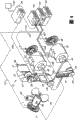
Fig. 4 is a skeleton view, has shown all parts of film induction system of the present invention, comprises control assembly, has removed the projector part so that clearly describe;
Fig. 5 has shown the film band with a plurality of specifications that is adapted at the use of film induction system;
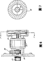
Fig. 6 is one and keeps sprocket and a light/digital encoder front elevation that the two is driven by a servomotor;
Fig. 7 is along the view of the 7-7 line intercepting of Fig. 6, has shown an optical encoder dish;
Fig. 8 is the schematic arrangement figure of the critical piece of film induction system;
Fig. 9 is a process flow diagram, has shown the communication path between the critical piece of film induction system.
Embodiment
The present invention includes a film induction system, indicated by reference number 10 usually, be used for film 12 is carried by a projector.As shown in Figure 4, film induction system 10 comprises two constant speed sprockets, and it comprises that one is given sprocket 22 and a maintenance sprocket 24, and it is positioned at the two opposite sides of gate 26.Intermittent film transport gear 28 so that film 12 frame by frames are intermittently sent to, passes through gate in common mode below gate 26 and then and between constant speed sprocket 22 and 24.Intermittent film transport gear 28 is under the Unite States Standard (USS) speed of 24 frame/seconds or under other desired arbitrary frame rate like this, and accurately each frame with film aligns with gate 26.Gate 26 comprises a hole 29.A projection light source 96 also has been described and by the dimmer plate 99 of a dimmer motor 90 driven in rotation.Giving between sprocket 22 and the gate 26 and intermittent film transport gear 28 and keeping between the sprocket 24, providing the lax of a film 12 to prevent film breakage with the form of lax film ring.
Variable-speed motor 30 will make output shaft 34 rotations of stretching out from each end of motor.One end of axle 34 is connected to be used for driving and keeps sprocket 34 to rotate.Axle 34 also drives 36 rotations of a driving wheel, and this driving wheel 36 transmits and connecting Timing Belt 38, and this Timing Belt 38 connects driving wheel 36 and second and takes turns 40.Like this, this is given sprocket 22 and keeps sprocket 24 to be connected 38 together by Timing Belt, and rotates with the constant speed consistent with variable-speed motor 30.
As shown in Figure 6, the axle 34 on variable-speed motor 30 is also carrying a numeral/optical encoder (" scrambler ") 46.Like this, give sprocket 22, keep sprocket 24 and scrambler 46 all to be connected on the axle 34, with identical rotational speed rotation.Scrambler 46, and relevant with servomotor 32 and dimmer motor 90 two other the scramblers that describe below, each all has a dish, and it has across a light source (LED) and a photodiode of dish both sides.As explained above, the rotation of dish will cause from photodiode launches pulse.
With reference to figure 4, intermittently servomotor 32 also makes output shaft 48 rotations of stretching out from each end of servomotor.One end of axle 48 is connected to be used to driving intermittent film transport gear 28 and rotates, and the other end of axle 48 is used to drive scrambler 52 rotations.
Fig. 5 has shown the part of film 12, and it has the film perforation 56 along the film edge.Be frame 58 between film perforation 56, for convenience of explanation, it is separated with perpendicular line 60.This part film 12 is 35mm films of standard, has different specifications on its length.The left side of film 12 and right side part have a specification, four film perforations 56 of its each frame 58 spans.The center section of film 12 has a specification, three film perforations 56 of its each frame 58 spans.Transition portion between these two specifications has one to trigger bar 62, will explain its function in detail below.Before discussed, Fig. 1 and Fig. 2 have shown two film specifications in further detail.
Fig. 4 has also shown 95, motor controllers of a principal computer (" CPU ") 94, a motor amplifier 93 and a direct supply 92, and they have formed power supply/control system (" control system ") together.Motor controller 94 comprises the controller that is used for variable-speed motor 30, servomotor 32 and dimmer motor 90.Similarly, motor amplifier 93 comprises the amplifier that is used for each motor 30,32 and 90.A sensor 97 is positioned at the inlet of close gate, and this sensor is to be used to survey specification to change information, triggers coding on the bar 62 at film, and it is forwarded to control system then.
To describe the operation of film induction system 10 below and carry out best understanding with reference to figure 4 in conjunction with Fig. 7 and 8.For convenience of description, suppose that the operated film specification of film induction system 10 initial setting up is that four film perforations of each frame span and frame rate are 24 frame/seconds of standard, conversion film specification subsequently is that the frame rate of three film perforations and projection was 30 frame/seconds for the span of each frame, for example when on identical projector sheet disc system, when these two film specifications are joined together.For convenience, these two film specifications are indicated as " 24-four specifications " and " 30-three specifications " below separately.
In this example, should adopt two control cards.A control card is one " a dimmer controller ", be used for dimmer motor and variable-speed motor, and another card is that one " intermittent controller " or " controller for servomotor " is to be used for servomotor.Any " control system " that relates to all should comprise these two controller and any relevant software.
At the beginning, according to by sensor 97 and contacting of a triggering bar 62 of opening the information that draws or from according to the acquiescence specification that exists ring, control system is set the state of the operation that is used for 24-four specifications.Therefore control system is also to dimmer motor 90 and variable-speed motor 30 energizes and order, with their output shaft of rotation under corresponding to the rotational speed that is fit to separately of 24-four specifications of 35mm film.The rotation that this will cause giving sprocket 22 and keep sprocket 24, and along the working direction of film, on the two opposite sides of gate 26 and intermittent film transport gear 28, supply with whereby and rolling with the film of measuring 12.Meanwhile, under 24 revolutions per seconds, variable-speed motor 30 rotary encoders 46, and dimmer motor 90 rotary shutters 99, and at the same time with identical speed rotary encoder 91.
Dimmer scrambler 91 is regulated by such rotation, so as and its relevant LED and the scrambler between the photodiode demarcate the passage of bar, corresponding with the position that reaches contract fully the first time of projector dimmer 99.When dimmer 99 cuts out, do not have light to be mapped in the screen and since frame advance caused in gate any running of film all will can not perceived by spectators.A demarcation pulse 101 is produced by dimmer motor encoder 91 passage of demarcation bar and this pulse is directed to motor controller 94.Motor Control 94 sends signal 102 to servomotor 32 with according to four profiles that film perforation moves of programming in advance then, makes the amount that film 12 rotation and a frame be equal to and advances.Like this, when dimmer motor 90 under 24 revolutions per seconds of rotations, intermittent running will be carried out advancing of one 24 frame/second, four film perforation films and indicate other variation up to signal.When film advanced, CPU95 was with the signal of continuous hunting from the indication specification change of sensor 97.When this change occurring, it is sent out 94 to motor controller and goes out signal, by introducing the desired specification that the change of various different motor outputs is operated with change of film specification.
With reference to figure 7 and Fig. 8, the order of incident generally is summarized as follows:
1. control system is opened and the motor controller initialization.
2. the mobile profile that will give tacit consent to is loaded on the controller for servomotor at intermittence from CPU95.
3. the film of acquiescence is given with frame rate and be loaded on the dimmer motor controller from CPU95.
4. variable-speed motor 30 and dimmer motor 90 are accelerated to a constant speed separately.
5. intermittently controller for servomotor reacts to a demarcation of the revolution pulse that is produced by dimmer motor encoder 91 continuously, make 28 pairs of mobile profiles of each loading of sprocket carry out the rotation at intermittence, and demarcating pulse for each that receive makes film 12 preceding forward one frames and stops projection subsequently.
6.CPU95 enter circulation, wherein indication of its continuous hunting changes the trigger pip of frame specification and operator scheme.When this change occurring, signal is sent to motor controller 94 with corresponding change vertical frame dimension degree and frame rate.
7. step 5 continues not to be interrupted up to CPU95 and runs into signal that another specification changes so that step 6 repeats, or from the "signal for " stop " of sensor 97, during this time, its indication motor controller shutdown system 10.
Under this mode, intermittent running is subordinated to dimmer motor 90 and is subordinated to intermittently controller for servomotor 94 according to the increment that film advances according to frame rate.
When intermittent film transport gear 28 was driven, film 12 was sent under the speed of the output pulse next frame of each dimmer scrambler 91.In this operating period, motor controller 94 guarantees that each film frame is accurately positioned in gate 26.This is to realize by following mode.
When intermittent film transport gear 28 is fed to film frame 58 position in gate 26, the quantity of advancing according to the scrambler line, the intermittently position of scrambler 52 detection servomotor/intermittent film transport gears (32,28) and the similarly position of film frame 58, and pass through feedback signal 103 and give controller for servomotor 94 with this feed information.Controller for servomotor 94 is compared this physical location and is correspondingly produced correction signal 102 indication servomotors 32 and quickens, slows down or stop with the ideal position that profile limited that moves according to order then.By this way, film frame 58 is moved quickly in the gate 26 and is very accurately located.
At incident order described above, aforesaid power supply/control system (control system) works in the following manner.Because highly sensitive intermittence, servomotor 32 needed very large electric power to supply with, must provide control system with high output DC source 92 in the short time.Provide management to this power supply 92 by motor amplifier 93, motor amplifier 93 is handled by motor controller 94 again successively.Therefore, said when here, be that controller 94 sends a signal to motor to quicken, to slow down or when stopping, in fact omit said controller 94 and sent a signal to motor amplifier 93, this amplifier 93 with the mode that moves or regulate that must obtain instructing, will output on the motor from the power measurement of power supply 92.
When film 12 advances by system 10 continuously, triggering bar 62 at one on the film will be detected before gate 26 by sensor 97.In one embodiment, trigger bar 62 and will carry magnetic, light or other the information that is coded in or is applied on the bar 62.It is desirable to, its junction between two film specifications, as shown in Figure 5.By way of example under this situation, by the detected information indication of sensor 97 film specifications from 24-four specifications to 30-three specifications change and corresponding to the change of this specification, the suitable pulse that produces by sensor 97 or the pulse 104 of series.This stream of pulses 104 is exaggerated and is sent to CPU95 in the amplifier (not shown), CPU95 plays the effect for the monitor of specifications vary, and changes motor output with suitable mobile profile loading electrical machine controller with the needs by the requirement of satisfying new operator scheme.
When specification changes, also must finish the change of frame rate.The identical coded trigger signal 104 that triggering bar 62 from film 12 obtains is used to finish two tasks.Trigger pip 104 is sent straight on motor controller 94 parts, the parts of the coded signal of the frame rate of its operation dimmer motor 90 and sign projector, so that dimmer motor 90 regulations speed correspondingly, it is to be increased to 30 revolutions per seconds in this case.Advance because must keep rotating synchronous film with dimmer, as previously described, intermittently servomotor 32 is subordinated to the running of dimmer 99.For each commentaries on classics of dimmer motor, be sent straight to the servomotor part at intermittence of controller 94 by a demarcation pulse of scrambler 91 generations.Controller 94 is again successively by motor amplifier 93, sends a signal to servomotor 32 so that the preceding forward one frame 58 of film, at this moment it be three film perforations.By this way, the frame rate of projection was increased to for 30 frame/seconds from 24 frame/seconds, and simultaneously the vertical frame dimension degree changes to three film perforations and can not bring the pause of operation from four film perforations.
What need important explanation is, in three film perforation specifications, as shown in Figure 2, the center line of frame, from left to right, through the center of a film film perforation 56.In the specification of four film perforations, as shown in Figure 1, yet the centerline bisects of frame is in half skew of a film perforation of the distance between two film perforations 56-have between two specifications.As a result, when from four film perforation specifications vary to three film perforation specification, the stride of first center to center must be the stride of one 3.5 film perforation.Do not have this initial demarcation to move, the image of projection will have incorrect frame, and the line of promptly separating film frame will appear in the screen.Thereafter, the interval of center to center will be constant three film perforations of every frame.Initially reorientate by means of intermittent film transport gear 28 with respect to the location of the tooth of stop position, film induction system 10 is designed to hold this skew.This can be by finishing the programming of controller 94, with startup equal the front and the frame size back and first stride of half (here being (4+3)/2=3.5 film perforation).This is demarcated stride and must accurately be carried out at the joint of film, with the needs of avoiding a frame error and correcting subsequently.By this way, to be positioned to maintain subsequently mobile of frame picture correct in three film perforation specifications location and all be that three film perforations advance to intermittent film transport gear 28.
What be worth valuing is the transfer capability that film induction system 10 is had, not still between above-described two film specifications, also between arbitrary other film specification.Like this, by means of further embodiment, film induction system 10 can be configured to use the film specification shown in Fig. 3, and this figure has illustrated the part of a film 12, and each frame 58 span is 2.5 film perforations therein.When film induction system 10 when four film perforation specifications are transformed into 2.5 film perforation specifications, (the initial stride of (4+2.5)/2=3.25) then is the follow-up stride of 2.5 film perforations, and finishes in the same manner as described above will to require one 3.25 film perforation.Similarly, the conversion from three film perforation specifications to 2.5 film perforation specifications will require first stride of one 2.75 film perforation.
Because sensor is preferably placed at the front of gate 26, the passage of the triggering bar 62 on sensor 97 will produce a pulse 104, and the time that this pulse 104 is positioned at the tram than film 12 in a conversion slightly in advance.Therefore, control system must provide a delay during the course.The time that postpones will be determined that by a constant and present pattern of the distance between sensor 97 and gate 26, system's 10 operations this pattern is by being determined in the coded message that triggers on the bar 62.Because it is slower that film 12 turns round in three film perforation specifications, will have prolongation slightly time delay.An interchangeable method that is used for the deviation post of compensation sensor 97 is to trigger the bar placed offset at the film of printing, and the amount that is offset equals the side-play amount of sensor from the film film perforation.In this manner, conversion will need to comprise the delay of a time very on time and not under the condition of any vertical frame dimension degree and frame rate.
When detecting on film 12 another by sensor 97 and trigger bar 62, another pulse 104 will be sent in the controller 94 by CPU95, it will send signal to all parts of system 10 to turn back in the operating conditions corresponding to 24-four specifications, as mentioned above, or take office what it can be in the operator scheme of the triggering bar regulation of coding.
Should consider that also triggering bar 62 can be the strip of foil that can not be magnetized, optical read sign indicating number, mechanical type trigger (for example film being carried out indentation, punching or impression) or other device that is fit to.In addition, as needs, sensor 97 can be substituted by a hand switch 130 on projector 14 or increase, to start one based on the specification conversion of projectionist to the visual observation of film 12.
Certainly, be understandable that, when the new reel of a film 12 with constant specification or disc are loaded onto on the projector, trigger bar 62 and can be placed on the beginning of film band or hand switch 130 and must be activated relevant operation with the order projector.Like this, trigger bar 62 or in case start hand switch 130, control system can be made needed adjusting, as mentioned above, carry the film 12 of specific standards to move by projector with operation film induction system 10 under the mode that is fit in case detect.
In addition, be understandable that, can provide additional scrambler each motor.When the relevant LED of a cover or photoelectricity/optical diode fault, this additional scrambler can assist in ensuring that system still can exempt failed operation.
The projection system of convertible specification described above will allow publisher and manufacturer to waste to eliminate with the specification release prints that replaces.Do them can save material and funds like this and can not reduce the image quality that spectators are given in demonstration simultaneously.The benefit of this processing will be above the saving at those initial stages, because waste is eliminated, copies and shorten and lighten.Therefore they load with less cost or even the sheet dish that can all install load and the preparation projection.
Now, 100 minutes film is 9000 feet long, considers weight, is loaded in the reel of 2000 feet of length.For they are presented in the screen, these reels must be joined together on specific projector.This process is called " connection " projection.It must be by professional's operation of all projectionists in this way.When theater management decision was shown other screen with this copy, it must often " be interrupted " and " be engaged again " again, because it is very heavy, was difficult for being moved to another projector by a reel ground from a projector., the present invention may provide new compact more version, will only need 6750 feet long (using three film perforation specification films) or 5625 feet long (using 2.5 specification films) in promptly identical 100 minutes.This will reduce length and weight, film may be loaded in the reel of an independent pre-installation and reel can be moved to another projector and need not " interrupt " and " reconnecting " projection from a projector.
The further advantage of film induction system 10 of the present invention is that it can carry out reviewing to whole sheet disc system automatically, and it is supplied with and the rolling films film induction system 10.In existing disc system, require the projectionist between the projection of the sheet dish that each is installed fully to system's load again.In addition, traditional film induction system adopts plant equipment, and it has hindered the execution of high speed reviewing., film induction system 10 of the present invention has been eliminated these plant equipment and has been utilized the full-electronic design, and it has avoided the intermittent running at reviewing sprocket 28 at intermittence operating period, therefore, provides a film antiport of high speed stably.By provide one to trigger bar at the film afterbody, by above-mentioned process, order motor 30 and 32 is with the high speed reviewing, thereby film induction system 10 can be by order to work under high speed reviewing pattern.
This shows, suitable programming by control system with sign from the specification on its triggering bar or frame rate with different motor are provided appropriate command under the new operator scheme that limits, working harmoniously, different or additional film specification may operate in the film induction system 10.By this way, among other situation, induction system 10 of the present invention can: (1) has between the film specification of different frame height backward and conversion forward; (2) change having between the specification of different frame rates; (3) automatically on the identical reel of film 12, carry out any specification conversion, and operation that can interrupting or stopping projector 14.Any single designing institute in the past proposes or the characteristics of suggestion all not have above in these three features one.
This combination of features will win buyer and budget space from the welcome less than 1,000,000 US dollars to 100,000,000 US dollars or the more manager of film company.Be everyone obtainable desired gauge the most at last.The economic benefit of the cost that reduces release prints can be brought to low budget film-making, the project effect of enhancing of the specification of big and higher rate can be brought to the film-making of high budget.
The publisher of film and show that the merchant also can welcome this dirigibility, the film specification of the specification that it is different with two (or more) is bonded on the reel of same film to have bigger alternative.Also can significantly reduce in the distribution of film and the cost and the hard work of displaying.In addition, for motion picture projection, the personnel of low technical ability of requirement and training just can finish the conversion between the film specification, and making system like this is very desirable to the theater staff of relatively low technical ability.
Although described and specific forms of the present invention be described, very clear the disengaging under the spirit and scope of the present invention, the different modification that can make.Therefore, except described in the claims that added, intentionally the present invention is limited.
Claims (21)
1. be used for film (12) is carried a film projector conveying device by film projector (10), wherein film (12) has a series of frame (58) and along a plurality of film perforations (56) at the edge of film (12), comprising:
Sprocket (22,24) with tooth is used to engage film perforation (56) and is used for film (12) is moved through projector (10);
Feed mechanism (28) intermittently, its frame by frame moves film (12) by the hole (29) in projector (10);
Former moving cell (30,32,90), it makes sprocket (22,24) rotation and activates intermittently feed mechanism (28); With
Control the controller (94,95) of former moving cell (30,32,90);
Wherein basis is about the frame rate of per second through the projection of the frame number of described hole (29), and controller (94,95) compatibly changes the rotational speed of sprocket (22,24) and the position of feed mechanism at intermittence (28); And
According to the film specification of the number that depends on the film perforation that each frame strode across on film (56), controller (94,95) compatibly changes the rotational speed of described gear and the location of feed mechanism at intermittence (28).
2. film projector conveying device as claimed in claim 1, it is characterized in that, described a plurality of sprocket comprises a pair of constant speed sprocket, and its each side in this hole (29) respectively has one, and it has tooth to be used to engage film perforation (56) and mobile film (12) by projector (10).
3. film projector conveying device as claimed in claim 2 is characterized in that, this feed mechanism at intermittence (28) comprises that an intermittent film transport gear with tooth sends film (12) to by this hole (29) to engage film perforation (56) and frame by frame.
4. film projector conveying device as claimed in claim 3 is characterized in that, this former moving cell (30,32,90) comprising:
First motor (30), it has rotation output (34) to rotate this to the constant speed sprocket;
Second motor (32), it has rotation output (48) to rotate described intermittent film transport gear off and on; With
Three-motor (90), it has rotation output to rotate a dimmer (99).
5. film projector conveying device as claimed in claim 4 is characterized in that, first motor (30) comprises that a servomotor and second motor (32) comprise a servomotor.
6. film projector conveying device as claimed in claim 5, it is characterized in that, this controller (94,95) control and coordinate first and second motor (30,32) and respond a trigger pip (104) to change the output of first and second motor respectively, with thus control this to the rotational speed of sprocket and the position of intermittent film transport gear, wherein this trigger pip (104) indication when the film (12) in projector (10) from one on film every frame (58) stride across the specification of the film perforation (56) of first predetermined number, change to the specification that another every frame (58) on film strides across the film perforation (56) of second predetermined number.
7. film projector conveying device as claimed in claim 5, it is characterized in that, this controller control (94,95) and coordinate three-motor (90) and respond a trigger pip (104) to change the output of three-motor, and thereby the rotational speed of control dimmer (99), wherein when film is from a pattern in projector for trigger pip (104) indication, wherein film is sent to the first predetermined frame rate, change to a pattern, wherein film is sent to the second predetermined frame rate.
8. film projector conveying device as claimed in claim 7, it is characterized in that, controller (94,95) output of response trigger pip (104) control second motor (32) is sent to carry out the first demarcation film, its span is by the preceding and the decision of the vertical frame dimension degree of the film specification that enters, and the output that continuous film is subsequently sent to has the span corresponding to the vertical frame dimension degree that enters specification.
9. film projector conveying device as claimed in claim 8 is characterized in that, this trigger pip (104) is based on the number of the film perforation (56) that every frame (58) is striden across on the film (12).
10. film projector conveying device as claimed in claim 9 is characterized in that, by electricity, magnetic, light or mechanical method, produces trigger pip automatically during projector work.
11. film projector conveying device as claimed in claim 9 is characterized in that, trigger pip (104) is manually to produce.
12. film projector conveying device as claimed in claim 2 is characterized in that, intermittently feed mechanism (28) comprises the toothed sprocket of a rotation.
13. film projector conveying device as claimed in claim 12 is characterized in that, intermittently feed mechanism (28) can rotate or provide to-and-fro movement intermittently to send film to.
14. film projector conveying device as claimed in claim 13 is characterized in that, this former moving cell (30,32,90) comprising:
First motor (30), it has rotation output (34) to rotate this to the constant speed sprocket;
Second motor (32), it has rotation or reciprocal output (48) to activate feed mechanism at this at intermittence; With
Three-motor (90), it has rotation output to rotate a dimmer (99).
15. film projector conveying device as claimed in claim 13 is characterized in that, this former moving cell (30,32,90) comprising:
First motor (30), it has rotation output (34) to rotate this to the constant speed sprocket; With
Second motor (32), it has rotation or reciprocal output to activate feed mechanism and dimmer at this at intermittence.
16. method of carrying film (12) by a projector (10), this projector has a plurality of sprockets (22 that film is sent in a rotation to, 24) former moving cell (30,32,90), with a feed mechanism (28) intermittently, its mobile frame by frame film is by a hole (29), it is characterized in that, it may further comprise the steps: the number according to the film perforation (56) that every frame strode across on film is determined the film specification, with determine film frame speed according to per second by the frame number of this hole (29), and control former moving cell (30 according to film specification and described film frame speed, 32,90) speed of rotation and the intermittently running of feed mechanism (28) to change sprocket (22,24).
17. method as claimed in claim 16 is characterized in that, first motor rotates a plurality of sprockets, and second motor is located feed mechanism at this at intermittence, dimmer of three-motor rotation, wherein:
Determine the film specification that enters according to the number of the film perforation that every frame strode across on film;
Send to according to determine first demarcation by the vertical frame dimension degree of film specification output and that enter;
Determine film frame speed according to per second by the frame number in this hole;
Control the rotation output (34) of first motor and the rotational speed of a plurality of sprockets according to the film specification;
According to described first demarcate the film specification send to and enter determine the second former moving cell output (48) and intermittence feed mechanism the position;
Control the output of three-motor (90) and the intermittently running of feed mechanism according to film frame speed.
18. method as claimed in claim 17 is characterized in that, also comprises producing trigger pip (104), it controls the output of first, second and three-motor, and wherein trigger pip is based on film specification and frame rate.
19. method as claimed in claim 18 is characterized in that, also comprises information is encoded on the film, it is used to identify film specification and frame rate and detects this information then to produce trigger pip (104).
20. method as claimed in claim 19 is characterized in that, also comprises sending trigger pip to a controller (94,95), it produces the secondary signal (105) of the rotation output of control first motor based on trigger pip.
21. method as claimed in claim 20, it is characterized in that, also being included on the film position corresponding to film specification and frame rate is provided with a plurality of triggering bars (62) and will identifies the information that changes film specification or frame rate and be encoded to and trigger on the bar and detect this information to produce trigger pip.
Applications Claiming Priority (2)
| Application Number | Priority Date | Filing Date | Title |
|---|---|---|---|
| US08/907,429 US6019473A (en) | 1996-02-07 | 1997-08-07 | Switchable format film projection system |
| US08/907,429 | 1997-08-07 |
Publications (2)
| Publication Number | Publication Date |
|---|---|
| CN1265747A CN1265747A (en) | 2000-09-06 |
| CN100456127C true CN100456127C (en) | 2009-01-28 |
Family
ID=25424085
Family Applications (1)
| Application Number | Title | Priority Date | Filing Date |
|---|---|---|---|
| CNB988079364A Expired - Fee Related CN100456127C (en) | 1997-08-07 | 1998-07-30 | Switchable format film projection system |
Country Status (14)
| Country | Link |
|---|---|
| US (1) | US6019473A (en) |
| EP (1) | EP1002257B1 (en) |
| JP (1) | JP4246377B2 (en) |
| KR (1) | KR100579781B1 (en) |
| CN (1) | CN100456127C (en) |
| AT (1) | ATE281661T1 (en) |
| AU (1) | AU757754B2 (en) |
| CA (1) | CA2298708C (en) |
| DE (1) | DE69827391T2 (en) |
| ES (1) | ES2232003T3 (en) |
| HK (1) | HK1030991A1 (en) |
| IL (1) | IL134208A (en) |
| RU (1) | RU2218586C2 (en) |
| WO (1) | WO1999008155A1 (en) |
Families Citing this family (10)
| Publication number | Priority date | Publication date | Assignee | Title |
|---|---|---|---|---|
| US20010043310A1 (en) * | 1996-02-07 | 2001-11-22 | Goodhill Dean K. | Switchable format film projection system |
| JPH11352590A (en) * | 1998-06-09 | 1999-12-24 | Sony Corp | Device and method for positioning film |
| US6529600B1 (en) * | 1998-06-25 | 2003-03-04 | Koninklijke Philips Electronics N.V. | Method and device for preventing piracy of video material from theater screens |
| DE10327771A1 (en) * | 2003-06-17 | 2005-01-05 | Arnold & Richter Cine Technik Gmbh & Co Betriebs Kg | Device for transporting a motion picture film |
| US20060072073A1 (en) * | 2003-08-28 | 2006-04-06 | Weisgerber Robert C | Method for producing and exhibiting three-dimensional motion pictures from a single strip of motion picture film |
| US8018569B2 (en) * | 2005-06-08 | 2011-09-13 | Maxivision Cinema Technology | Method and apparatus for inhibiting the piracy of motion pictures |
| WO2007085950A2 (en) * | 2006-01-27 | 2007-08-02 | Imax Corporation | Methods and systems for digitally re-mastering of 2d and 3d motion pictures for exhibition with enhanced visual quality |
| EP2160037A3 (en) * | 2006-06-23 | 2010-11-17 | Imax Corporation | Methods and systems for converting 2D motion pictures for stereoscopic 3D exhibition |
| CN110115594A (en) * | 2011-09-26 | 2019-08-13 | 皇家飞利浦有限公司 | Motion control to imaging system rotary frame and subject's supporter |
| US9275603B2 (en) * | 2012-04-23 | 2016-03-01 | Intel Corporation | Driving displays at cinematic frame rates |
Citations (5)
| Publication number | Priority date | Publication date | Assignee | Title |
|---|---|---|---|---|
| US4150886A (en) * | 1976-08-26 | 1979-04-24 | Airborne Mfg. Co. | Motion picture projector system |
| US4702577A (en) * | 1984-08-17 | 1987-10-27 | Dedo Weigert Film Gmbh | Film transport device |
| CN2049370U (en) * | 1989-06-24 | 1989-12-13 | 张玉申 | Automatic staggered frame setting apparatus for cine-projector |
| US5534954A (en) * | 1991-12-12 | 1996-07-09 | United Artists Theatre Circuit, Inc. | Motion picture system |
| CN1210598A (en) * | 1996-02-07 | 1999-03-10 | 迪安·K·古德希尔 | Switchable pulldown film projection system |
Family Cites Families (29)
| Publication number | Priority date | Publication date | Assignee | Title |
|---|---|---|---|---|
| US1318610A (en) * | 1919-10-14 | sereinsky | ||
| US1921494A (en) * | 1927-04-21 | 1933-08-08 | Wildhaber Ernest | Method of producing audible pictures |
| US1835743A (en) * | 1929-08-14 | 1931-12-08 | Bell Telephone Labor Inc | Sound picture system |
| US1999754A (en) * | 1932-04-22 | 1935-04-30 | Arthur M Hyde | Recording and projecting sound on film apparatus |
| US2079572A (en) * | 1933-01-03 | 1937-05-04 | Ripley Corp | Method of and apparatus for recording sound on the edge of film |
| US3285087A (en) * | 1963-07-24 | 1966-11-15 | Panopix Res Inc | Variable speed drive sprocket |
| US3565521A (en) * | 1968-11-26 | 1971-02-23 | Lawrence W Butler | Variable size film framing and transport system |
| JPS5016931B1 (en) * | 1970-03-03 | 1975-06-17 | ||
| US3819258A (en) * | 1972-09-20 | 1974-06-25 | Scripps Clemans | Film framing and transport system |
| US3865738A (en) * | 1974-01-21 | 1975-02-11 | Miklos Lente | Method of making motion pictures |
| DE2558747A1 (en) * | 1975-12-24 | 1977-07-07 | Rollei Werke Franke Heidecke | SMALL TONE FILM PROJECTOR |
| US4143951A (en) * | 1975-12-27 | 1979-03-13 | Canon Kabushiki Kaisha | Cine-projector |
| US4105311A (en) * | 1976-11-08 | 1978-08-08 | Eprad Incorporated | Film transport system |
| US4360254A (en) * | 1980-03-27 | 1982-11-23 | Mangum-Sickles Industries, Inc. | Camera having stepper motor driven film transport/registration sprocket |
| US4437742A (en) * | 1980-10-09 | 1984-03-20 | Minolta Camera Kabushiki Kaisha | Camera capable of automatically responding to data coded on film |
| US4678298A (en) * | 1982-11-22 | 1987-07-07 | Zoran Perisic | Method and apparatus for three-dimensional photography |
| US4697896A (en) * | 1986-09-30 | 1987-10-06 | Showscan Film Corporation | Electronic projector |
| FR2622707A1 (en) * | 1987-10-30 | 1989-05-05 | Aaton Sa | METHOD FOR REGISTERING, ON THE MARGINAL PART OF A PERFORATED CINEMATOGRAPHIC FILM, CODE INFORMATION |
| US4900293A (en) * | 1989-05-26 | 1990-02-13 | Mclendon Donald C | 4:3 perf conversion sprocket |
| US5096286A (en) * | 1990-03-07 | 1992-03-17 | Weisgerber Robert C | Method for transitioning between two different frame rates during a showing of a single motion picture film |
| US5218388A (en) * | 1991-06-21 | 1993-06-08 | Purdy William H | Film monitor for use in automating movie theater operation |
| US5739895A (en) * | 1991-12-12 | 1998-04-14 | United Artists Theatre Circuit, Inc. | Film saving system |
| US5543869A (en) * | 1991-12-12 | 1996-08-06 | Vetter; Richard | Frame registration |
| US5312304A (en) * | 1992-11-18 | 1994-05-17 | United Artists Entertainment | Convertible sprocket for motion picture film |
| JPH06208179A (en) * | 1993-01-08 | 1994-07-26 | Sony Corp | Cinematographic film and its reproducing device |
| US5341182A (en) * | 1993-01-14 | 1994-08-23 | Pioneer Technology Corporation | Motion picture projection apparatus |
| US5539527A (en) * | 1993-03-11 | 1996-07-23 | Matsushita Electric Industrial Co., Ltd. | System for non-linear video editing |
| US5450140A (en) * | 1993-04-21 | 1995-09-12 | Washino; Kinya | Personal-computer-based video production system |
| US5506639A (en) * | 1993-05-07 | 1996-04-09 | Frazen; Nancy E. | Method and apparatus for editing motion picture film and synchronized sound |
-
1997
- 1997-08-07 US US08/907,429 patent/US6019473A/en not_active Expired - Lifetime
-
1998
- 1998-07-30 ES ES98939134T patent/ES2232003T3/en not_active Expired - Lifetime
- 1998-07-30 WO PCT/US1998/015902 patent/WO1999008155A1/en active IP Right Grant
- 1998-07-30 IL IL13420898A patent/IL134208A/en not_active IP Right Cessation
- 1998-07-30 EP EP98939134A patent/EP1002257B1/en not_active Expired - Lifetime
- 1998-07-30 RU RU2000101829/28A patent/RU2218586C2/en not_active IP Right Cessation
- 1998-07-30 AU AU87624/98A patent/AU757754B2/en not_active Ceased
- 1998-07-30 DE DE69827391T patent/DE69827391T2/en not_active Expired - Lifetime
- 1998-07-30 CN CNB988079364A patent/CN100456127C/en not_active Expired - Fee Related
- 1998-07-30 AT AT98939134T patent/ATE281661T1/en not_active IP Right Cessation
- 1998-07-30 JP JP2000506565A patent/JP4246377B2/en not_active Expired - Fee Related
- 1998-07-30 CA CA002298708A patent/CA2298708C/en not_active Expired - Fee Related
- 1998-07-30 KR KR1020007001289A patent/KR100579781B1/en not_active IP Right Cessation
-
2001
- 2001-03-06 HK HK01101594.7A patent/HK1030991A1/en not_active IP Right Cessation
Patent Citations (5)
| Publication number | Priority date | Publication date | Assignee | Title |
|---|---|---|---|---|
| US4150886A (en) * | 1976-08-26 | 1979-04-24 | Airborne Mfg. Co. | Motion picture projector system |
| US4702577A (en) * | 1984-08-17 | 1987-10-27 | Dedo Weigert Film Gmbh | Film transport device |
| CN2049370U (en) * | 1989-06-24 | 1989-12-13 | 张玉申 | Automatic staggered frame setting apparatus for cine-projector |
| US5534954A (en) * | 1991-12-12 | 1996-07-09 | United Artists Theatre Circuit, Inc. | Motion picture system |
| CN1210598A (en) * | 1996-02-07 | 1999-03-10 | 迪安·K·古德希尔 | Switchable pulldown film projection system |
Also Published As
| Publication number | Publication date |
|---|---|
| IL134208A (en) | 2004-05-12 |
| DE69827391T2 (en) | 2005-10-27 |
| CA2298708C (en) | 2007-10-23 |
| HK1030991A1 (en) | 2001-05-25 |
| IL134208A0 (en) | 2001-04-30 |
| EP1002257A1 (en) | 2000-05-24 |
| US6019473A (en) | 2000-02-01 |
| CA2298708A1 (en) | 1999-02-18 |
| CN1265747A (en) | 2000-09-06 |
| AU757754B2 (en) | 2003-03-06 |
| KR100579781B1 (en) | 2006-05-12 |
| DE69827391D1 (en) | 2004-12-09 |
| JP2001512854A (en) | 2001-08-28 |
| WO1999008155A1 (en) | 1999-02-18 |
| KR20010022694A (en) | 2001-03-26 |
| EP1002257B1 (en) | 2004-11-03 |
| AU8762498A (en) | 1999-03-01 |
| ATE281661T1 (en) | 2004-11-15 |
| JP4246377B2 (en) | 2009-04-02 |
| RU2218586C2 (en) | 2003-12-10 |
| ES2232003T3 (en) | 2005-05-16 |
Similar Documents
| Publication | Publication Date | Title |
|---|---|---|
| CN100456127C (en) | Switchable format film projection system | |
| US2925753A (en) | Sound projector | |
| JPS6159497B2 (en) | ||
| AU783710B2 (en) | System and method for registering motion picture film | |
| US5946076A (en) | Switchable pulldown film projection system | |
| US5875020A (en) | Motion picture projection system | |
| US20060061732A1 (en) | Switchable format film projection system | |
| US3944349A (en) | Shutter assembly | |
| US3551039A (en) | System for unattended projection of closed loop film | |
| EP0191559A1 (en) | A system for exhibiting motion pictures | |
| MXPA00001213A (en) | Switchable format film projection system | |
| WO1993006520A1 (en) | Method and apparatus for producing and displaying a motion picture | |
| US2434518A (en) | Motion-picture projector | |
| WO2006000886A1 (en) | Synchronization check systems and methods for film projectors | |
| CN1187886A (en) | Reversing film projection system |
Legal Events
| Date | Code | Title | Description |
|---|---|---|---|
| C06 | Publication | ||
| PB01 | Publication | ||
| C10 | Entry into substantive examination | ||
| SE01 | Entry into force of request for substantive examination | ||
| REG | Reference to a national code |
Ref country code: HK Ref legal event code: GR Ref document number: 1061504 Country of ref document: HK |
|
| C14 | Grant of patent or utility model | ||
| GR01 | Patent grant | ||
| REG | Reference to a national code |
Ref country code: HK Ref legal event code: GR Ref document number: 1030991 Country of ref document: HK |
|
| C17 | Cessation of patent right | ||
| CF01 | Termination of patent right due to non-payment of annual fee |
Granted publication date: 20090128 Termination date: 20120730 |