JP4246377B2 - Format switchable film projection system - Google Patents
Format switchable film projection system Download PDFInfo
- Publication number
- JP4246377B2 JP4246377B2 JP2000506565A JP2000506565A JP4246377B2 JP 4246377 B2 JP4246377 B2 JP 4246377B2 JP 2000506565 A JP2000506565 A JP 2000506565A JP 2000506565 A JP2000506565 A JP 2000506565A JP 4246377 B2 JP4246377 B2 JP 4246377B2
- Authority
- JP
- Japan
- Prior art keywords
- film
- frame
- projector
- motor
- format
- Prior art date
- Legal status (The legal status is an assumption and is not a legal conclusion. Google has not performed a legal analysis and makes no representation as to the accuracy of the status listed.)
- Expired - Fee Related
Links
Images


Classifications
-
- G—PHYSICS
- G03—PHOTOGRAPHY; CINEMATOGRAPHY; ANALOGOUS TECHNIQUES USING WAVES OTHER THAN OPTICAL WAVES; ELECTROGRAPHY; HOLOGRAPHY
- G03B—APPARATUS OR ARRANGEMENTS FOR TAKING PHOTOGRAPHS OR FOR PROJECTING OR VIEWING THEM; APPARATUS OR ARRANGEMENTS EMPLOYING ANALOGOUS TECHNIQUES USING WAVES OTHER THAN OPTICAL WAVES; ACCESSORIES THEREFOR
- G03B21/00—Projectors or projection-type viewers; Accessories therefor
- G03B21/14—Details
- G03B21/32—Details specially adapted for motion-picture projection
- G03B21/43—Driving mechanisms
- G03B21/44—Mechanisms transmitting motion to film-strip feed; Mechanical linking of shutter and intermittent feed
- G03B21/48—Mechanisms transmitting motion to film-strip feed; Mechanical linking of shutter and intermittent feed for altering frame speed; for regulating constancy of film speed
-
- G—PHYSICS
- G03—PHOTOGRAPHY; CINEMATOGRAPHY; ANALOGOUS TECHNIQUES USING WAVES OTHER THAN OPTICAL WAVES; ELECTROGRAPHY; HOLOGRAPHY
- G03B—APPARATUS OR ARRANGEMENTS FOR TAKING PHOTOGRAPHS OR FOR PROJECTING OR VIEWING THEM; APPARATUS OR ARRANGEMENTS EMPLOYING ANALOGOUS TECHNIQUES USING WAVES OTHER THAN OPTICAL WAVES; ACCESSORIES THEREFOR
- G03B1/00—Film strip handling
- G03B1/18—Moving film strip by means which act on the film between the ends thereof
- G03B1/20—Acting means
- G03B1/24—Sprockets engaging holes in the film
-
- G—PHYSICS
- G03—PHOTOGRAPHY; CINEMATOGRAPHY; ANALOGOUS TECHNIQUES USING WAVES OTHER THAN OPTICAL WAVES; ELECTROGRAPHY; HOLOGRAPHY
- G03B—APPARATUS OR ARRANGEMENTS FOR TAKING PHOTOGRAPHS OR FOR PROJECTING OR VIEWING THEM; APPARATUS OR ARRANGEMENTS EMPLOYING ANALOGOUS TECHNIQUES USING WAVES OTHER THAN OPTICAL WAVES; ACCESSORIES THEREFOR
- G03B21/00—Projectors or projection-type viewers; Accessories therefor
- G03B21/001—Slide projectors
-
- G—PHYSICS
- G03—PHOTOGRAPHY; CINEMATOGRAPHY; ANALOGOUS TECHNIQUES USING WAVES OTHER THAN OPTICAL WAVES; ELECTROGRAPHY; HOLOGRAPHY
- G03B—APPARATUS OR ARRANGEMENTS FOR TAKING PHOTOGRAPHS OR FOR PROJECTING OR VIEWING THEM; APPARATUS OR ARRANGEMENTS EMPLOYING ANALOGOUS TECHNIQUES USING WAVES OTHER THAN OPTICAL WAVES; ACCESSORIES THEREFOR
- G03B21/00—Projectors or projection-type viewers; Accessories therefor
- G03B21/14—Details
- G03B21/32—Details specially adapted for motion-picture projection
- G03B21/43—Driving mechanisms
-
- H—ELECTRICITY
- H04—ELECTRIC COMMUNICATION TECHNIQUE
- H04N—PICTORIAL COMMUNICATION, e.g. TELEVISION
- H04N9/00—Details of colour television systems
- H04N9/12—Picture reproducers
- H04N9/31—Projection devices for colour picture display, e.g. using electronic spatial light modulators [ESLM]
- H04N9/3141—Constructional details thereof
Abstract
Description
【0001】
(技術分野)
本発明は映画映写機用のフィルム送りシステムに関し、特に、一つのフィルムフォーマットのフィルムプリントを送り、次に他のフィルムフォーマットに切り換え、その切換えの間に映写機の運転に中断を生じないでフィルムプリントを送ることができるフィルム映写機の運動機構に関する。
【0002】
(背景技術)
従来の劇場用35mmフィルムの映画映写機は秒速24コマの標準レートでフィルムゲートを経由して断続的にフィルムを引っ張るモータ駆動スプロケットホイールを採用している。フィルムの送りの間は定速モータによって駆動される回転シャッターが、ブラーリング(画像のボケ)を防ぐためにスクリーンをブラックアウト(画面を暗転する)していた。観客は残像として知られている現象によって、このブラックアウトに気が付かない。フィルムは、両方の側の定速度スプロケットによって、フィルムゲートと断続スプロケットへ供給され、フィルムゲートと断続スプロケットから送り出される。フィルムゲートにおいて生じる断続フィルム運動は、断続スプロケットの両方の側にあって定速度スプロケットによって保持されるフィルムループによって平滑化される。現在の映画館用映写機は殆ど専ら機械型である。典型的には、単一の同期モータが、マルチドライブギアを軸受けしている駆動シャフトを駆動し、そのマルチドライブギアがシャッターおよび定速度スプロケットおよび断続スプロケットを秒速24コマのUS標準のコマ速度に対応する単一速度で駆動する。断続スプロケットは、ジェネヴァ機構と称する装置によって駆動され、その装置の目的は、ドライブシャフトの1回転を、断続スプロケットの90度の回転と、それに引き続く映像投影のための停止時間とに変換することにある。16枚歯のスプロケットの90度の回転は4パーフォレーション(送り孔)のコマ送り(すなわち、1プルダウン)を生じる。4パーフォレーションコマの標準は1800年代の後半に、映写アスペクト比1.33:1に適応するために設定されたものであり、以後変更されていない。その結果、市販されている35mmの映写機も秒速24コマで4パーフォレーションプルダウンに設計される。
【0003】
ほぼ総ての映画館用35mm映写機は機械的設計であるが、電子的プルダウンに特徴をもっている若干の特殊な映写機が市販されている。これらの設計はフィルムゲート中でフィルムを送ったり位置決めさせるためジェネヴァ装置の代わりに高応答のサーボモータに頼っている。
【0004】
アナモルフィック光学系は真の(true)広角度スクリーン投映に使用されている。このアナモルフィック光学系は、撮影中には、アスペクト比が2.4:1の映像をアスペクト比が1.33:1の4パーフォレーションカメラのコマに絞り込み、次に、投映中にはその映像を絞り込みから解放する。1950年代の後半には、アナモルフィックカメラおよびレンズに頼る必要なく観客に「半ワイドスクリーン光景」を提供するために、1.85スクリーンフォーマットが開発された。現在発売されているフィルムのほぼ85%が1.85:1フォーマットを使用している。この投映アスペクト比を達成するために投射ゲートの開口部に単にマスクが差し込まれる。このマスクは、映写コマの上部と下部の部分を覆うので、それによって、映像の高さに対する幅の比を増加させる。その結果、マスクされた部分に曝される映像を見ることはできない。
【0005】
図1はこのことを非常に明瞭に示している。斜線領域64は、4パーフォレーションコマ高さをもつ1.85:1映写フォーマットにおいては、使用されないでむだにされる、使用可能なフィルム部分を示す。参照番号66で示されている部分は光学的アナログ音声トラックに対応する。むだにされるフィルム領域の問題の一つの解決方法は、図1に示されているのと同じ投映面積を与えるけれど上部と下部にむだにされる映像部分がない、代わりのコマ高さ規格に変更することである。このような代わりのコマ規格として図2に示されている3パーフォレーションコマがある。先にはマスクによってむだにされた面積の大部分を取り除くことによって、同じ映写面積を、4パーフォレーションフィルムの代わりに3パーフォレーションフィルムに適合させることができる。その結果、「むだにされる」面積の除去は、フィルムの販売プリントフィート数、したがって、コストを25%削減する。
【0006】
3パーフォレーションフォーマットは正しい方向の1段階であるが、それでもなお、上部と下部に、投映中にマスクしなければならないむだになる面積がいくらかあるので、フィルム節約上、究極なものであるとはいえない。図3は1.85:1フォーマットに対する究極のコマ高さを示し、この場合にはむだになるフィルム面積は殆どない。1.85規格フォーマットは、光学的音声トラックのためにフィルムの左側に保留されているスペースによって限定されている、設定された画像幅を有する。この限定されたコマ幅は、1.85:1アスペクト比と共に、0.446インチのコマ高さを確定する。コマの間のスペースとして千分の一の若干倍が付加されるときには、この高さは、正確に2.5パーフォレーションのフィルム長に該当する。2.5パーフォレーションプルダウンフォーマットは、4パーフォレーションフォーマットに比較すると、約37.5%の販売プリントフィート数の減少に該当する。
【0007】
フィルム節約とその経済的な効果が、現在の最も重要な問題点の1つであるけれど、画質の向上は、映画の将来にとってさらに重要であろう。新しいディジタル技術がホーム番組の質を向上させるに従って、映画館の上映もそれに比例して観客を引きつけるために向上しなければならないであろう。映画館の映像の画質向上は2つの方法で可能である。1つの方法は、コマサイズを増加させることである。他の方法は、カメラと映写のコマ送り速度を増加させることである。これらの両者ともフィルムが撮影され映写される仕方によって変化する。
【0008】
1. コマサイズの増加
1.85フォーマットに関して、フィルム上の画像を、従来アナログ音声トラックに占められていた領域に広げることによってコマサイズを増加させることが可能である。光学的アナログ音声トラックは、冗長ディジタルトラックに置き換えられる。この新しいフォーマットは、1996年提出のSer.No.08/646,777の特許出願にさらに完全に説明されている。このフォーマットは、ここでは、引用によって挿入しておく。この拡大されたコマを3パーフォレーションプルダウンと組み合わせることによって、フィルム使用量の25%の減少と同時に画像拡張の32%増しを達成することができる。別法としてコマ高さを5パーフォレーションに増加させ、かつ、この非常に拡大されたフォーマットに対して新規なアナモルフィックレンズを使用すれば、解像度にもかなりの増加を生じるであろう。しかし、この方法は、より大量のフィルムの使用に導くであろう。
【0009】
2.カメラおよび投映のコマ送り速度の増加
カメラおよび投映のコマ送り速度を24コマ/秒から30コマ/秒または48コマ/秒までも増加させることは、観衆にかなり高められた現実感を与えることが証明されている。フィルム映写は瞬時的であるので、高いコマ送り速度はちらつきを除去し、それによって、もし、コマ送り速度が高くなければそのようなちらつきを増強させるであろう大きな映像の輝度を許容すると共に、同時に、認識される解像度を高め、かつ、「ストロービング」として知られている運動異常を除去する。ストロービングは、物体が画面を横切って映像運動の幻影を妨げる速度と角度で運動するときに生じる。ストロービングをしている物体は、1つの位置から他の位置に不自然な態様でジャンプするように見える。この問題は、撮影と映写において高いコマ送り速度を用いることによって解決する。
【0010】
前掲の記述から、種々の理由のために非常に望ましいけれども現存する映写システムに適合しないという問題を有するいくつかの異なるコマ高さと映写コマ送り速度があることが明らかである。異なるフォーマットのフィルムを映画館の上映に首尾よく導入するためには、これらの設備が、総てのフォーマットで動作することができる映写機を備えていることが必要である。アナモルフィック広角度スクリーン上映には、引き続き全4パーフォレーションコマを必要とするであろうから、これらの映写システムは、標準の4パーフォレーション、24コマ/秒フォーマットフィルムと、他のフォーマットのフィルムとを映写する機能を保持していることが必須である。さらに、いくつかの「クラシック」フィルムや、その他(例えば、予告編や公共の布告)の、原始の4パーフォレーションフォーマットのままのフィルムがある。
【0011】
3または4パーフォレーションフォーマットプルダウンを現存の映写機に備えることを試みる幾つかのデザインが現在までに提案されてきている。しかし、これらのデザインに関する基本的な問題は、これらのデザインが、フォーマットをどちらかの方向に変化させるとき、映写機の中のそれぞれのスプロケットを手動で切り替えることを必要とするという点にある。このことによって、これらのデザインは、時間および人力の制約によって、全く非実用的になる。本発明は、完全に自動的な、切り替え可能なプルダウン・コマ送り速度の映写機の動作を導入する。この動作によって、技術者からの不適切な気配りなしに、また、上映におけるためらいなしに、同じ映画館映写機に種々の異なるフォーマットのフィルムを「バック−ツウ−バック」方式で上映させることができる。このようにして、本発明は、従来のデザインに関する問題を解決し、さらに、関連した利点を提供することができる。
【0012】
(発明の開示)
本発明は、映写機を通ってフィルムを送るためのフィルム送りシステムを有する切り換え可能フォーマットフィルム映写システムを提供する。以下の発明の議論において、用語「フォーマット」は、映写システムデザインまたは動作に影響があるフィルムプリント特性を総合的に引用し、映写コマ送り速度(コマ/秒)、(パーフォレーションの数)、コマアスペクト比(高さに対する幅)、および光学システム(球状とは反対にアナモルフィック)を含む。例えば、「変更フォーマットが用いられることができる」というフレーズ中で総合的な意味で用いられるときには、上記の特性の任意の結合を含むことが意図されている。しかし、幾つかの例では、「フォーマット」は、例えば、「4パーフォレーションフォーマット」のように、さらに特定された引用において用いられる。そのような場合には、それは、単に「4パーフォレーション」のコマ高さ特性をもつプリントフォーマットを指す。「モード」という用語は、引用されたフォーマットの要求に対応する、本発明の映写機の動作の選択可能の動作条件を示すために、一般的な意味に用いられる。
【0013】
フィルム送りシステムは、フィルム映写機運動機構または「ヘッド」と呼称され、フィルム上のパーフォレーションと噛み合うための歯を備えたスプロケットと、スプロケットを回転させ、フィルムを、映写機の開口を通過してコマ単位で送る駆動要素を備えている。本発明によると、コントロールシステムは、駆動要素を調整し、それによって、各コマの区間で測られるパーフォレーションの数に関するフィルムフォーマットに従って、および、設計されたコマ送り速度に従って、スプロケットの回転速度と位置を維持し、または変化させるために設けられている。
【0014】
本発明の1つの実施例においては、フィルム送りシステムは、フィルムゲートの各側に1つずつ配置された1対のスプロケットと、1対のスプロケットの間にあって、フィルムゲートの開口を通過してフィルムをコマ単位で送る断続スプロケットを備えている。1対のスプロケットの回転速度は、可変スピードモータによって定められ、断続スプロケットの回転速度と位置決めは、他のモータ、例えば、高応答サーボモータ(断続サーボモータ)によって決定される。この実施例においては、これら2つのモータは、フィルム送りの駆動要素を備えている。しかし、希望に応じて、単一のモータ、または3個(または、それ以上)のモータを駆動要素として使用することができる。また、この実施例においては、別個の第3のモータがシャッターブレードを回転させるために使用される。このシャッターブレードは、同期運動状態に維持されなけえばならない映写機機構の一部である。フィルムのコマ送り速度のどのような変化も、シャッターの回転速度の対応する変化が必要である。したがって、シャッターモータは、可変スピードモータか、または、サーボモータでなければならない。
【0015】
コントロールシステムは、可変スピードモータ、断続サーボモータおよびシャッターモータを調整し、フィルムフォーマットを示すトリガー信号に応答する。例えば、トリガー信号はフィルムストリップ上にエンコードされセンサーによって読み出される情報であることができる。入力したトリガー信号の型に基づいて、コントロールシステムは、シャッターモータスピードと可変スピードモータの出力を変化させ、可変スピードモータは、さらに、1対のスプロケットの回転速度とフィルムコマの送り速度を変化させる。
【0016】
可変スピードモータとシャッターモータは、それぞれ、等しい間隔の半径方向の線で指標付けされている、軽量で透明な円板を有するデジタル光エンコーダ(「エンコーダ」)を駆動する。光源、例えば、LEDとフォトダイオードは、動作時に、光源がフォトダイオードに向かって光ビームを投射するように、エンコーダの円板を跨いでいる。円板を回転させると、エンコーダ線の通過によって、光ビームが遮断されパルスがフォトダイオードから発射される。これらのパルスの出力によって、コントロールシステムはモータと断続スプロケットの正確な回転位置についての情報を継続的に得ることができ、そうして、エンコーダ板上の線数の関数である精度で、モータを加速し、減速し、または、正確な位置で停止させることができる。通常、工業の運動制御には、1000本またはそれ以上の線をもつエンコーダ円板が使用される。または、半径方向の線をもつ透明円板の代わりに、半径方向のスロットをもつ不透明円板を使用することができる。光エンコーダ技術は、充分に確立されていて運動制御工業に数年間使用されている。
【0017】
各コマ送りのための、サーボモータの初期運動は、CPUと結合している従来のサーボモータ運動制御カード(「コントローラ」)の出力によって制御される。この場合、CPUは、サーボモータに、エンコーダ計数値で表した加速度、速度、角度位置を含む、予め定められた運動曲線の選択をさせるように、プログラムされている。曲線の選択は、種々のコマ高さとコマ送り速度の必要性に適合するために必要である。このことは、運動曲線の角変位成分とその運動をするために割り当てられた時間を変更することによって達成される。実際の運動コマンドは、指標ポールがフォトダイオードを通過したときに、シャッターモータエンコーダに起源を発する。このエンコーダは、次に、1コマだけフィルム送りを開始するためにコントロールカードを経てサーボモータへ給送されるパルスを発生する。また、サーボモータは、前掲のように、エンコーダを駆動し、エンコーダは、フィルム位置に関するデジタル化された情報をコントローラに供給することができるように、連続的にサーボモータの位置を監視する。それによって、コントローラは、適当な位置で断続的にフィルム運動を停止し、フィルムゲートの位置で、各コマの適切な位置合わせを保証することができる。
【0018】
トリガー信号は、例えば、1コマ当たりのパーフォレーション数が4パーフォレーションのコマをもつフィルムから1コマ当たりのパーフォレーション数が3パーフォレーションのコマをもつフィルムへの変化、または、指定されるコマ送り速度が24コマ/秒から30コマ/秒への変化、または両方の変化がある場合のように、フィルムがフォーマットを変化させる時を指示するように設計される。勿論、トリガー信号は、多くの異なる種類のフォーマットの間の変化を表すことができる。そうして、一般的に言えば、トリガー信号は、映写機のフィルムフォーマットが、ある所定のパーフォレーション数のコマをもつフォーマットから他の異なる所定のパーフォレーション数のコマをもつフォーマットへ何時変化するかを指示し、または、ある所定のコマ送り速度から他の所定のコマ送り速度へ、何時変化するか、または、その両方が何時変化するかを指示するように設計されている。
【0019】
フィルムフォーマットの変化を示すトリガー信号は、種々の方法で生成することができる。1つの実施例においては、トリガー信号は、コントロールシステムに結合されたセンサによって電子的に生成される。センサは、例えば、それがフィルムフォーマットの変化を指示するために、映写機中に入れられたときに、フィルムに担持されているエンコードされた情報を読み出すように設計されている。その情報は、薄膜または磁性ストリップ上にエンコードされてもよく、光学的な読み出しコードであってもよろしいし、または、機械的その他の適当な手段によって、エンコードされてもよい。または、トリガー信号は、フィルム操作者によるフィルムの視覚的検査に基づいて手動で生成されることもできる。トリガー信号を生成する他の適当な手段は明らかであり、本発明は、手動または電子的に生成される信号に限定されるものではない。
【0020】
信号生成の方法に関係なく、本発明の重要な特徴は、フィルム送りシステムが映写機の操作を中断したり、そうでなければ停止したりすることなく、フィルムフォーマット間の変化に適合されることである。このことによって、例えば、異なるフィルムフォーマットが同一のフィルムプラッターシステム上で継ぎ合わされるように、フィルムフォーマット間が切り換えられるときに、どのような遅延も除去される。プラッターシステムは、映写機用のフィルム送りおよび巻き取り貯蔵モジュールを有する。システムはかなりの学習を必要としないで操作が簡単でかつ信頼性があるように設計されているので、フィルムフォーマット間の切換えをするために、特別な技量を必要としない。さらに、フィルム送りシステムは、逆に、現存する35mm映写に適合するように設計されることができるので、ランプハウス、蓄電器、プラッターシステムやその他の構成要素を含む全映写システムを取り換える場合に必要な高い経費を回避することができる。
【0021】
本発明の他の特徴と利点は、例によって本発明の原理を説明する添付図面を参照して、以下の本発明の記述から明らかになるであろう。
【0022】
(発明を実施するための最良の形態)
本発明は、全体として参照番号10によって参照される、映写機を通って送られるフィルム12用のフィルム送りシステムにおいて実施される。図4に示されているように、フィルム送りシステム10は、送りスプロケット22と巻き取りスプロケット24を有し、フィルムゲート26の両側に位置する2つの定速度スプロケットを有する。断続スプロケット28は、通常の方式でフィルムゲートを通ってフィルム12を1コマ単位で断続的に送るために、フィルムゲート26の直ぐ下で定速度スプロケット22、24の間に位置決めされている。このようにして、断続スプロケット28は、毎秒24コマのU.S.規格の速度、または、その他の任意の所望のコマ送り速度で、フィルム12の各コマをフィルムゲート26に正確に位置合わせする。フィルムゲートは、また、開口29を有する。映写光源96と、シャッターモータ90によって回転されるシャッターブレード99もまた、図示されている。フィルム12のたるみ部分が、フィルムの破損を防止するために、弛んだフィルムのループの形で送りスプロケット22とフィルムゲート26の間、および、断続スプロケット28と巻き取りスプロケット24の間に設けられている。
【0023】
フィルム送りシステム10は、また、可変スピードモータ30とサーボモータ32を有する駆動要素を含んでいる。本実施例における可変スピードモータ30も、また、サーボモータであることもできる。しかし、以下に説明するように、可変スピードモータ30は、また、3スピードモータであることができ、必要によっては、追加のスピードを具備することができる。断続サーボモータ32は、高応答特性のサーボモータでなければならない。そして、断続ユニットを含む回転成分の総ては、スプロケットが断続デューティサイクルによって要求される割合で加速および減速されることができるために、最小の極性慣性モーメントをもっていなければならない。または、駆動要素は、スプロケット22、24、および28を駆動し、それらの速度と位置を変化させるために機械的またはその他の手段をもつ単一モータを有することができるということも考えられる。
【0024】
可変スピードモータ30は、モータの各端部から延びる出力シャフト34を回転させる。シャフト34の一端は、巻き取りスプロケット24を回転させるために、該スプロケット24に連結されている。シャフト34は、タイミングベルト38を支持する駆動ホイール36を回転させる。そのタイミングベルト38は、駆動ホイール36を第2の駆動ホイール40に結合する。第4の駆動ホイール40は、送りスプロケット22を回転するシャフト42に連結されている。このようにして、送りスプロケット22と巻き取りスプロケット24とは、タイミングベルト38によって連結され、可変スピードモータ30によって定速度で連動して回転される。
【0025】
図6にも示されているように、可変スピードモータ30上のシャフト34は、ディジタル光エンコーダ(「エンコーダ」)46を支持している。従って、送りスプロケット22、巻き取りスプロケット24およびエンコーダ46は、総て、可変スピードモータ30のシャフト34に共通に結合され、同一の回転速度で回転する。エンコーダ46と、サーボモータ32およびシャッターモータ90と連動している下記の2つの他のエンコーダとは、それぞれ、光源(LED)と、フォトダイオードとを有する円板を備え、光源とフォトダイオードは、円板を跨いでいる。上記のように、円板の回転によって、フォトダイオードからパルスが発射される。
【0026】
再び、図4を参照して、断続サーボモータ32も該サーボモータの各端部から延びる出力シャフト48を回転させる。シャフト48の一端は、断続スプロケット28を回転させるために、該断続スプロケット28に連結され、シャフト48の他の端部は、エンコーダ52を回転させる。
【0027】
図5は、縁部に沿って複数のパーフォレーション56をもつフィルム12の一部分を示している。パーフォレーション56の間には、コマ58があり、コマ58は説明のために、鉛直線60によって分離されている。このフィルム12の断片は、35mm規格のフィルムであり、その全長に亘って異なるフォーマットをもつように示されている。フィルム12の左および右の区域は、各コマ58の区間に4つのパーフォレーション56があるフォーマットを持っている。フィルム12の中央の区域は、各コマ58の区間に3つのパーフォレーション56があるフォーマットを持っている。これらの2つのフォーマットの間の移行部分は、トリガーストリップ62によって表され、そのトリガーストリップ62の機能は、以下にさらに詳細に説明される。前に議論された図1と2には、2つのフィルムフォーマットがさらに詳細に示されている。
【0028】
図4には、また、ホストコンピュータ(「CPU」)95、モータコントローラ94、モータ増幅器93およびd.c.電源92が示されていて、これらは、一緒になって電力・コントロールシステム(「コントロールシステム」)を構成している。モータコントローラ94は、可変スピードモータ30、サーボモータ32、およびシャッターモータ90のためのコントローラを含んでいる。同様にモータ増幅器93は、これらのモータ30、32、90の各々用の増幅器を含んでいる。センサー97は、フィルムゲートの入り口の近くに配置され、フィルムトリガーストリップ62上にエンコードされているフォーマット変化情報を検出するために使用される。フォーマット変化情報は、次にコントロールシステムへ中継される。
【0029】
フィルム送りシステム10の動作は、以下に記載され、図7および8に関連して図4を参照して最もよく理解される。これを記述するために、フィルム送りシステム10は、各コマの区間に4つのパーフォレーションがあり、かつ、コマ送り速度が標準の24コマ/秒であるフィルムフォーマットを用いた動作を行うように初期設定され、次に、フィルム送りシステム10は、各コマの区間に3つのパーフォレーションがあり、かつ、映写コマ送り速度が30コマ/秒であるフィルムフォーマットに切り換えられると仮定する。この場合、これらの2つのフィルムフォーマットが同一の映写機のプラッターシステム上で継ぎ合わされるときのように切り換えられるものとする。説明の便宜上、以下の記載においては、これら2つのフィルムフォーマットを、それぞれ24−4フォーマットおよび30−3フォーマットと呼称する。
【0030】
この場合には、2つのコントロールカードが使用されなければならない。1つのカードは、シャッターモータと可変スピードモータ用の「シャッターコントローラ」であり、他方のカードは、断続サーボモータ用の「断続コントローラ」または、「サーボモータコントローラ」である。また、「コントロールシステム」の引用は、両方のコントローラおよびそれに関連する総てのソフトウエアを含んでいるものとする。
【0031】
最初に、コントロールシステムは、センサー97が最初のトリガーストリップ62と接触することから導き出される情報、または、ループ(フィルム)に存在するデフォルトモードから導き出される情報によって、24−4フォーマットの動作をするように条件の設定が行われる。したがって、シャッターモータ90および可変スピードモータ30は起動され、そうして、コントロールシステムによって、24−4フォーマットをもつ35mmフィルムに対応するそれぞれの適当な回転スピードで出力シャフトを回転するように制御される。このことによって、送りスプロケット22と巻き取りスプロケット24のフィルム送り方向への回転が生じ、それによって、フィルムゲート26と断続スプロケット28との両側で等量のフィルム12の供給と巻き取りが生じる。同時に、可変スピードモータ30はエンコーダ46を回転させ、そうして、シャッターモータ90は、シャッター99を24回転/秒で回転させ、一方、同時にエンコーダ91を同一の速度で回転させる。
【0032】
シャッターエンコーダ91の回転位置は、当該シャッターエンコーダに関連するLEDとフォトダイオードの間をエンコーダ板の指標ポールが通過することと、映写機シャッター99が最初に完全遮断位置に到達することとが対応するように、予め調整されている。シャッター99が遮断すると、光はスクリーンに到達することができない。そうして、フィルムが、コマ送りによって、フィルムゲート26中をどのように移動しても、その移動は観客によって認識されないであろう。指標ポールの通過によって、シャッターモータエンコーダ91は指標パルス101を生成する。そして、このパルスはモータコントローラ94に出力される。次に、モータコントローラ94は、予めプログラムされた4パーフォレーション運動曲線に従って、1コマに対応する回転角だけフィルム12を送るために、信号102をサーボモータ32に送信する。このようにして、24回転/秒で回転するシャッターモータ90によって、24コマ/秒、4パーフォレーションフィルム送りの断続運動が、他フォーマットのフィルム送りを行うように信号が生成されるまで後続する。フィルムが送られるに従って、CPU95は、継続的に、センサー97からの、フォーマットの変化を示す信号を監視する。この変化が起こると、CPUは、到来するフィルムフォーマットが要求する、種々のモータの出力を変化させることによって動作のモードを変化させるように、モータコントローラ94に信号を送信する。
【0033】
図7および8を参照して、イベントのシーケンスを次のように、総括することができる。
【0034】
1.コントロールシステムがスイッチオンされ、モータコントローラ94が初期化される。
2.デフォルト運動曲線がCPU95から断続サーボモータコントローラへロードされる。
3.デフォルトのフィルム送りとコマ送り速度が、CPU95からシャッターモータコントローラへロードされる。
4.可変スピードモータ30とシャッターモータ90がそれぞれ一定速度へ加速される。
5.断続サーボモータコントローラは継続的にシャッターモータエンコーダ91によって生成された1回転1個の指標パルスに応答し、スプロケット28をロードされた運動曲線に従って断続的に回転させ、および、フィルム12を、受信した指標パルス毎に1コマずつ送り、次に投映のために停止させる。
6.CPU95は、フィルムを登録し、その場合には、CPU95は、フィルムフォーマットの変化を示すトリガー信号、したがって、動作モードを継続的に監視する。この変化が生じたときには、その変化に応じてコマ高さおよびコマ送り速度を変更するために、信号をモータコントローラ94に送信する。
7.ステップ5は、ステップ6を繰り返させる他のフォーマット変化信号をCPU95が入力し、または、センサー97からのストップ信号をCPU95が入力するまで、中断しないで継続する。そうして、CPU95がストップ信号を入力したとき、CPU95は、システム10を終了することをモータコントローラ94に指示する。
【0035】
このように、断続運動は、コマ送り速度に関してはシャッターモータ90に連動するように連結され、フィルム送りの増加に関しては断続サーボモータコントローラ94に連動するように連結される。
【0036】
断続スプロケット28が駆動されるとき、フィルム12はシャッターエンコーダ91の出力パルス101毎に1コマの割合で、フィルムゲート26を通って送られる。この動作の間に、モータコントローラ94は、各フィルムコマがフィルムゲート26中で正確に位置決めされることを保証する。このことは、次のようにして達成される。 断続スプロケット28がフィルムコマ58をフィルムゲート26中の位置に送るとき、断続エンコーダ52は、送られたエンコーダ線の数によって、サーボモータ32または断続スプロケット28の位置を検出し、そして同様に、フィルムコマ58の位置を検出する。そうして、断続エンコーダ52は、この情報をフィードバック信号103によってサーボモータコントローラ94に供給する。サーボモータコントローラ94は、次に、この実際の位置と、指令された運動曲線によって定義される理想位置とを比較し、それに相応して、サーボモータ32に加速、減速、または停止することを命令する補正信号102を生成する。このようにして、フィルムコマ58は急速にフィルムゲート26中に移動し、最高の精度で位置決めされる。
【0037】
上記のイベントのシーケンスに関して、前掲の電力・コントロールシステム(「コントロールシステム」)は、次のように機能する。高応答断続サーボモータ32は、非常に短い時間に非常に大きな電力供給を必要とするので、高出力のd.c.電力源92を有するコントロールシステムを備えることが必要である。この電力源92の管理はモータ増幅器93によって提供され、そのモータ増幅器93は、さらに、モータコントローラ94によって管理されている。したがって、コントローラ94が、加速、減速、または停止させるためにモータへ信号を送るということは、実際に要約すれば、コントローラ94がモータ増幅器93に信号を送り、そのモータ増幅器93は、指令された運動または調節を達成するために必要な仕方で電力源92からモータへ電力を、計量しながら供給するために用いられる、ということになる。
【0038】
フィルム12がシステム10を通過して進み続けるとき、フィルム上のトリガーストリップ62の1つがフィルムゲート26の前で、センサー97によって読み出されるであろう。1つの実施例においては、トリガーストリップ62は、磁気的、光学的、またはその他の方法でエンコードされ、または、ストリップ62上に貼り付けられた情報を持っている。理想的には、トリガーストリップ62は、図5に示されているように、2つのフィルムフォーマット間の継ぎ目に配置されている。この場合に、センサー97によって読み出される情報は、例えば、24−4フォーマットから30−3フォーマットへのフィルムフォーマットの変化を示し、そうして、適当なパルスまたは、パルス列104が、このフォーマットの変化に対応して、センサー97によって生成される。このパルス列104は、増幅器(図示されていない)で増幅され、CPU95へ出力される。CPU95は、フォーマット変化に対してウオッチドッグとして働き、モータコントローラ94に、新たな動作モードの要件を満たすために必要に応じてモータ出力を変化させるように、適当な運動曲線をロードする。
【0039】
フォーマットの切換えが起こると同時に、コマ送り速度の変化も実施されなければならない。フィルム12上のトリガーストリップ62から導き出され、同一のエンコードが行われたトリガー信号104が両方のタスクを達成するために用いられる。トリガー信号104は、シャッターモータ90のために機能するモータコントローラ94部へ出力される。そして、エンコードされた信号の、映写機のコマ送り速度を識別する成分は、それに応じて、シャッターモータ90に速度を調節させる。この速度は、この場合には、30回転/秒である。前記したように、フィルム送りは、常に、シャッターの回転に同期した状態に維持されなければならないので、断続サーボモータ32は、シャッター99の運動に連動するように連結される。シャッターモータ90の1回転毎に指標パルスがエンコーダ91によって生成され、その指標パルスは、コントローラ94の断続サーボモータ部へ出力される。コントローラ94は、さらに、フィルム12を1コマ58(この場合には、1コマは3パーフォレーションである)だけ送るために、信号を、モータ増幅器93を経由してサーボモータ32に送信する。このようにして、コマ高さが4パーフォレーションから3パーフォレーションに変化するのと同時に、動作の中断なしに、映写機のコマ送り速度は、24コマ/秒から30コマ/秒に増加される。
【0040】
図2に示されている3パーフォレーションフォーマットにおいては、左から右へのコマ中心線は、フィルムパーフォレーションの中心を通る。しかし、図1に示されている4パーフォレーションフォーマットにおいては、コマ中心線は、2つのフィルムパーフォレーション56の間の間隔を2等分し、2つのフォーマットの間には、1パーフォレーションの2分の1のずれがある。その結果、4パーフォレーションフォーマットから3パーフォレーションフォーマットに移行するとき、中心から中心へのステップは、3.5パーフォレーションのステップでなければならない。もし、この初期割り出しの移動がなければ、投影された映像は、2つのフィルムコマを分離する線がスクリーン上に現れるであろうという意味で、正しくないコマ送りになるであろう。その後は、中心から中心への間隔は、1コマあたり一定の3パーフォレーションであろう。フィルム送りシステム10は、断続スプロケット28の停止位置における歯の向きに対して該断続スプロケット28の位置を初期再調整することによって、このずれを適応させるように設計されている。このことは、送り出されるコマのサイズと到来するコマのサイズの和の2分の1(この場合には、(4+3)/2=3.5パーフォレーション)に等しい1番目のステップを開始するように、コントローラ94をプログラムすることによって達成される。この割り出し工程は、コマ送り誤差とそれに続く補正の必要を回避するために、フィルムの継ぎ目で正確に実行されなければならない。このようにして、断続スプロケット28は、3パーフォレーションフォーマットで適切な映像コマ送りを維持するように、向き調整される。そして、それに続く総ての運動は、3パーフォレーション送りである。
【0041】
フィルム送りシステム10は、上記の2つのフィルムフォーマットの間の切換えばかりでなく、その他の任意の数のフィルムフォーマット間の切換えが可能であるということが大切である。したがって、さらに他の例によると、フィルム送りシステム10は、各コマ58の区間に2.5パーフォレーションがあるフィルムの断片を図示している図3に示されているようなフィルムフォーマットを使用するように構成することができる。フィルム送りシステム10が4パーフォレーションフォーマットから2.5パーフォレーションフォーマットに切り換わるときには、3.25パーフォレーション((4+2.5)/2=3.25)の初期ステップとその後に続く2.5パーフォレーションのステップが必要である。そして、それは、前掲の方法と同様の方法で達成することができる。同様に、3パーフォレーションフォーマットから2.5パーフォレーションフォーマットへの切換えは、2.75パーフォレーションの最初のステップが必要である。
【0042】
センサ97は、フィルムゲート26に先立つ位置に位置決めされることが望ましいので、フィルム12が切換えのための適正な位置にくる僅かに前に、トリガストリップ62がセンサ97上を通過することによるパルス104が発生する。その結果、コントロールシステムは、プロセスの中に遅延を生じなければならない。遅延期間は、センサ97とフィルムゲート26との間の距離(定数)と、トリガーストリップ上のエンコードされた情報から定められるシステム10の現在の動作モードによって定まる。フィルム12は、3パーフォレーションフォーマットにおいてはゆっくりと運動するので、遅延期間は、僅かに長い。センサ97のずれた位置を補償する他の手段は、フィルム開口29からのセンサーのずれに等しい量だけフィルムプリント上におけるトリガーストリップの配置をずらすこと(すなわち、遅延)である。このようにして、切換えは、時間遅れを含むことを必要とせずに、コマ高さまたはコマ送り速度の任意の条件のもとで正確なタイミングで行うことができる。
【0043】
フィルム12上のもう1つのトリガーストリップ62がセンサ97によって読み出されるときには、もう1つのパルス104がCPU95を経由してコントローラ94に送信される。CPU95は、上記の24−4フォーマットに対応する動作条件または、エンコードされたトリガーストリップ上に特定されている任意の他の動作モードに戻るために、システム10のすべての構成要素に信号を送る。
【0044】
トリガーストリップ62は、消磁することができない薄膜ストリップ、光学的読み出しコード、機械的トリガー(例えば、フィルムに刻み目をつける、フィルムを穿孔する、フィルムを型押しする)または、その他の適当な手段でもよいということも分かっている。また、もし必要ならば、センサー97を、映写技師によるフィルム12の視覚的検査に基づいてフォーマット切換えを開始するために映写機14上の手動スイッチ130に置き換えることもできるし、または、センサー97を、手動スイッチ130で増強することができる。
【0045】
一定のフォーマットをもっているフィルム12の新しいリールまたは、プラッタ−が映写機に装填されたときには、トリガーストリップ62は、フィルム片の先頭に置かれることができ、または、手動スイッチ130が映写機の適当な動作を指令するために作動されなければならないことは、勿論、理解されるであろう。したがって、コントロールシステムは、トリガーストリップ62を読み出し、または、手動スイッチ130を作動すると、フィルム12が映写機を通って走行する特定のフォーマットに適した仕方でフィルム送りシステム10を動作させるために、上記のように、必要な調整をすることができる。
【0046】
さらに、モータの各々に冗長エンコーダを備えることができるということは大切なことである。この冗長性は、協働するLED、または、フォトセルまたはフォトダイオードのセットの1つに誤動作がある場合に障害を受けない動作を保証することを助ける。上記の切換え可能フォーマット映写システムによって、販売者は、無駄を除く変更されたフォーマットで公開プリントを製作することができる。そうするときには、販売者は、顧客に示される映像の品質を同時に低下させることなく、材料とお金を節約することができる。この方法の利点は、さらに、これらの初期の節約の範囲を超えたところにも存在する。無駄が除かれたので、プリントは物理的に短くなり、かつ、軽くなる。その結果、プリントは、より少ない経費で出荷され、全プラッター付きで、すぐにでも映写できる状態で出荷されることさえできる。
【0047】
現在、100分フィルムの長さは9,000フィートであり、そうして、重さの理由で、2000フィートのリールで出荷されている。これらのリールは、それらが上映されるスクリーンのための特定の映写機上で継ぎ合わされる。この処理は、映画を「搭載する」と称せられている。このことは、例えば、映写技師のような、技術をもった個人によって行われなければならない。映画館の管理者が、そのプリントを他のスクリーンに移動することを決定するときには、プリントは、通常、「解体」されて再び「再搭載」されなければならない。その理由は、プリントは、プラッターに乗せたままでは非常に重くて映写機から映写機に容易に移動することができないからである。しかし、本発明によって可能にされた新しい、さらにコンパクトな形においては、その同じ100分フィルムは、僅かに6,750フィート長(3パーフォレーションフォーマットのフィルムを用いて)、または、5,625フィート(2.5パーフォレーションフォーマットのフィルムを用いて)である。この減少した長さと重さにおいては、フィルムを1個の予め搭載されたリールで出荷し、そのリールを、映画の「解体」および「再搭載」なしに映写機から映写機に移動することが可能になる。
【0048】
本発明のフィルム送りシステム10のもう1つの利点は、フィルム送りシステム10へフィルムを給送し、フィルム送りシステム10からフィルムを巻き取る全プラッターシステムを自動的に巻き戻す機能を有する点にある。従来のプラッターシステムにおいては、映写技師は、各々の完全に搭載されたプラッターの上映の間(1つの上映と次の上映との間)にシステムを再セットすることを要求されている。さらに、従来のフィルム送りシステムは、高速フィルム巻き戻しの実行を妨げる機械的装置を使用している。しかし、本発明のフィルム送りシステム10は、これらの機械的装置を避けて、巻き戻し操作の間には、断続スプロケット28における断続運動を回避し、したがって、逆に、滑らかで高速のフィルム運動を提供する完全に電子的設計を使用している。フィルム送りシステム10は、フィルム12の終端部に、前掲のプロセスによって、モータ30および32に高速でフィルムを巻き戻すことを指令するトリガーストリップ62を備えることによって、高速巻き戻しモードで動作することを指令されることができる。
【0049】
(産業上の利用可能性)
以上に記述から、コントロールシステムがそのトリガーストリップコードからフォーマットまたはコマ送り速度を識別し、かつ、新たに定義された動作モードで種々のモータが調和して動作するための適当なコマンドをそれらのモータに与える適切なプログラムによって、異なる、または追加のフィルムフォーマットがフィルム送りシステム10上を送られることができることがわかる。このように、本発明のフィルム送りシステム10は、特に、(1)異なるコマ高さをもつフィルムフォーマットの間で両方向の切換えを行うことができ、(2)異なるフィルムコマ送り速度をもつフォーマットの間で切換えを行うことができ、(3)映写機14の動作を中断または停止させることなく、フィルム12の同一のプラッター上で自動的に任意のフォーマット変換を行うことができる。今まで、単一のデザインで、これらの3つの特徴の2つ以上の特徴を有し、または示唆すらしたものは提案されていない。
【0050】
この特徴の結合は、百万ドル以下から1億ドルに亘る予算によって、製作者や製作責任者によって活発に声援される筈である。最終的には、どの人にも利用可能な理想的なフォーマットがあるであろう。低予算の製作は低い公開プリント費という経済的利点を享受することができる。そして高予算のフィルムは、より大きく、より高速なフォーマットの高められた上映価値を享受することができる。
【0051】
この融通性は、2つ(または、それ以上)のフィルムフォーマットをフィルムの同一のプラッター上に乗せることにおいて、より多くの選択を持つことができるので、フィルムの販売者や出品者によっても歓迎されるであろう。このようにして、フィルムの販売と出品にかかる経費と努力は著しく減少する。さらに、映写のために、フィルムフォーマット間の切換えを実施するための技術と訓練は、殆ど必要がない。したがって、このことによって、このシステムは、比較的に未熟練の映画館従業者による操作に理想的である。
【0052】
本発明の特別な形態を説明し、記述したけれど、本発明の精神と範囲から逸脱することなく、種々の変更が可能であることは明らかである。したがって、本発明は、添付の特許請求の範囲によって限定される以外には、限定されることが意図されていない。
【図面の簡単な説明】
【図1】 各コマの区間に4パーフォレーションがある1フォーマットのフィルムの一部分である。
【図2】 各コマの区間に3パーフォレーションがある他のフォーマットのフィルムの一部分である。
【図3】 各コマの区間に2.5パーフォレーションがある更に他のフォーマットのフィルムの一部分である。
【図4】 コントロール成分を含み、見やすくするために映写機の部分が切り離されている、本発明のフィルム送りシステムの全構成要素を示す斜視図である。
【図5】 フィルム送りシステムに使用するために適している多重フォーマットのフィルムストリップを示す図である。
【図6】 いずれもサーボモータで駆動される巻き取りスプロケットとデジタル光エンコーダの正面図である。
【図7】 図6の7−7線に沿ってとられた光エンコーダ板の正面図である。
【図8】 フィルム送りシステムの主要な構成要素の図式的なレイアウトである。
【図9】 フィルム送りシステムの主要な構成要素間の通信経路を示すフロー図である。[0001]
(Technical field)
The present invention relates to a film feeding system for a movie projector, and in particular, sends a film print in one film format, then switches to another film format, and without interrupting the operation of the projector during the switching. The present invention relates to a motion mechanism of a film projector that can be sent.
[0002]
(Background technology)
Conventional 35mm film cinema projectors for theater use a motor driven sprocket wheel that pulls the film intermittently through a film gate at a standard rate of 24 frames per second. During film feeding, a rotary shutter driven by a constant speed motor blacked out the screen (darkens the screen) to prevent blurring (blurred images). The audience is unaware of this blackout due to a phenomenon known as afterimage. Film is fed to and out of the film gate and interrupted sprocket by constant speed sprockets on both sides. Intermittent film motion that occurs at the film gate is smoothed by film loops that are held by the constant speed sprocket on both sides of the intermittent sprocket. Current cinema projectors are almost exclusively mechanical. Typically, a single synchronous motor drives a drive shaft bearing a multi-drive gear that multiplies the shutter, constant speed sprocket and intermittent sprocket to a US standard frame speed of 24 frames per second. Drive at the corresponding single speed. The intermittent sprocket is driven by a device called a Geneva mechanism, the purpose of which is to convert one rotation of the drive shaft into a 90 degree rotation of the intermittent sprocket followed by a stop time for image projection. is there. A 90-degree rotation of a 16-tooth sprocket results in frame perforation (ie, 1 pull-down) of 4 perforations. The standard for four perforation frames was set in the latter half of the 1800s to accommodate a projection aspect ratio of 1.33: 1 and has not been changed since. As a result, a commercially available 35 mm projector is also designed with 4 perforation pull-downs at 24 frames per second.
[0003]
Almost all 35mm movie projectors for movie theaters are mechanically designed, but some special projectors that are characterized by electronic pull-down are commercially available. These designs rely on high-response servomotors instead of Geneva devices to move and position the film in the film gate.
[0004]
Anamorphic optics are used for true wide-angle screen projection. This anamorphic optical system narrows an image with an aspect ratio of 2.4: 1 to a frame of a 4 perforation camera with an aspect ratio of 1.33: 1 during shooting, and then the image during projection. Release from narrowing. In the late 1950s, a 1.85 screen format was developed to provide a “half-wide screen view” to the audience without having to rely on anamorphic cameras and lenses. Nearly 85% of films currently on the market use the 1.85: 1 format. In order to achieve this projection aspect ratio, a mask is simply inserted into the opening of the projection gate. This mask covers the upper and lower portions of the projection frame, thereby increasing the ratio of width to height of the image. As a result, the image exposed to the masked portion cannot be seen.
[0005]
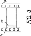
FIG. 1 shows this very clearly. The hatched
[0006]
The 3 perforation format is one step in the right direction, but it's still the ultimate in savings because there is some wasted area at the top and bottom that must be masked during projection. Absent. FIG. 3 shows the ultimate frame height for the 1.85: 1 format, in which case there is little wasted film area. The 1.85 standard format has a set image width that is limited by the space reserved on the left side of the film for the optical audio track. This limited frame width, together with a 1.85: 1 aspect ratio, establishes a 0.446 inch frame height. This height corresponds exactly to a film length of 2.5 perforations when a little more than a thousandth is added as the space between frames. The 2.5 perforation pull-down format represents a reduction in sales print footage of approximately 37.5% compared to the 4 perforation format.
[0007]
While film savings and its economic benefits are one of the most important issues today, improving image quality will be even more important for the future of cinema. As new digital technologies improve the quality of home programs, cinema screenings will have to be improved to attract audiences proportionally. There are two ways to improve the image quality of movie theaters. One method is to increase the frame size. Another method is to increase the frame rate of the camera and projection. Both of these vary depending on how the film is filmed and projected.
[0008]
1. Increase frame size
For the 1.85 format, it is possible to increase the frame size by expanding the image on the film to the area previously occupied by the analog audio track. The optical analog audio track is replaced with a redundant digital track. This new format is a Ser. No. This is described more fully in the 08 / 646,777 patent application. This format is inserted here by reference. By combining this enlarged frame with a 3 perforation pulldown, a 25% increase in image expansion can be achieved simultaneously with a 25% reduction in film usage. Alternatively, increasing the frame height to 5 perforations and using a new anamorphic lens for this very enlarged format would result in a significant increase in resolution. However, this method will lead to the use of larger amounts of film.
[0009]
2. Increase frame rate for camera and projection
Increasing the camera and projection frame rate from 24 frames / second to 30 frames / second or 48 frames / second has proven to give the audience a much enhanced reality. Since film projection is instantaneous, a high frame rate eliminates flicker, thereby allowing large video brightness that would otherwise increase such flicker if the frame rate is not high, At the same time, it increases the perceived resolution and eliminates the movement anomaly known as “stroving”. Stroving occurs when an object moves at a speed and angle that hinders the illusion of video motion across the screen. A strobing object appears to jump in an unnatural manner from one position to another. This problem is solved by using a high frame rate for shooting and projection.
[0010]
From the preceding description, it is clear that there are a number of different frame heights and projection frame feed rates that are highly desirable for various reasons but have the problem of not being compatible with existing projection systems. In order to successfully introduce films of different formats into theater screenings, it is necessary that these facilities be equipped with projectors that can operate in all formats. Since anamorphic wide-angle screen screening will continue to require all four perforation frames, these projection systems will combine standard four-perforation, 24-frame / second format film with other formats of film. It is essential to have the ability to project. In addition, there are some “classic” films and others (eg, trailers and public decree) that remain in the original 4-perforation format.
[0011]
Several designs have been proposed to date that attempt to equip existing projectors with 3 or 4 perforation format pull-downs. However, the basic problem with these designs is that they require manual switching of each sprocket in the projector when changing the format in either direction. This makes these designs quite impractical due to time and manpower constraints. The present invention introduces a fully automatic, switchable pull-down frame rate projector operation. This action allows a variety of different format films to be shown in a “back-to-back” fashion on the same cinema projector without undue attention from the technician and without hesitation in the screening. In this way, the present invention solves the problems associated with conventional designs and provides related advantages.
[0012]
(Disclosure of the Invention)
The present invention provides a switchable format film projection system having a film feeding system for feeding film through a projector. In the discussion of the invention below, the term “format” refers generally to film print characteristics that affect projection system design or operation, including projection frame rate (frames / second), (number of perforations), frame aspect. Including ratio (width to height), and optical system (anamorphic as opposed to spherical). For example, when used in an overall sense in the phrase “change format can be used”, it is intended to include any combination of the above characteristics. However, in some examples, “format” is used in more specific citations, eg, “4 perforation format”. In such a case, it simply refers to a print format with a frame height characteristic of “4 perforations”. The term “mode” is used in a general sense to indicate a selectable operating condition of the operation of the projector of the present invention that corresponds to a request for a quoted format.
[0013]
The film feed system, called the film projector motion mechanism or “head”, sprockets with teeth for meshing with the perforations on the film, rotates the sprocket, and passes the film through the projector opening frame by frame. It has a drive element to send. According to the present invention, the control system adjusts the drive element, thereby adjusting the rotational speed and position of the sprocket according to the film format for the number of perforations measured in each frame interval and according to the designed frame feed rate. Provided to maintain or change.
[0014]
In one embodiment of the present invention, the film feeding system includes a pair of sprockets, one on each side of the film gate, and a pair of sprockets, passing through the opening in the film gate and passing through the film. It is equipped with an intermittent sprocket that sends frame by frame. The rotational speed of the pair of sprockets is determined by a variable speed motor, and the rotational speed and positioning of the intermittent sprocket are determined by another motor, for example, a high response servo motor (intermittent servo motor). In this embodiment, these two motors are provided with film feed drive elements. However, a single motor or three (or more) motors can be used as drive elements as desired. Also in this embodiment, a separate third motor is used to rotate the shutter blade. This shutter blade is part of the projector mechanism that must be maintained in a synchronized motion state. Any change in film frame speed requires a corresponding change in shutter rotation speed. Therefore, the shutter motor must be a variable speed motor or a servo motor.
[0015]
The control system adjusts the variable speed motor, intermittent servo motor and shutter motor and responds to a trigger signal indicating the film format. For example, the trigger signal can be information encoded on a filmstrip and read by a sensor. Based on the type of trigger signal input, the control system changes the shutter motor speed and the output of the variable speed motor, and the variable speed motor further changes the rotation speed of the pair of sprockets and the feed speed of the film frame. .
[0016]
The variable speed motor and the shutter motor each drive a digital optical encoder (“encoder”) having a light, transparent disc, indexed by equally spaced radial lines. Light sources, such as LEDs and photodiodes, straddle the encoder disc so that, in operation, the light sources project a light beam toward the photodiode. When the disc is rotated, the light beam is blocked by the passage of the encoder line and a pulse is emitted from the photodiode. With the output of these pulses, the control system can continuously obtain information about the exact rotational position of the motor and intermittent sprockets, so that the motor can be operated with an accuracy that is a function of the number of lines on the encoder plate. It can be accelerated, decelerated, or stopped at a precise position. Typically, industrial motion control uses encoder disks with 1000 or more lines. Alternatively, an opaque disk with radial slots can be used instead of a transparent disk with radial lines. Optical encoder technology is well established and has been used in the motion control industry for several years.
[0017]
The initial motion of the servo motor for each frame advance is controlled by the output of a conventional servo motor motion control card (“controller”) coupled to the CPU. In this case, the CPU is programmed to cause the servo motor to select a predetermined motion curve including the acceleration, speed, and angular position represented by the encoder count value. The selection of the curve is necessary to meet the needs of various frame heights and frame feed rates. This is accomplished by changing the angular displacement component of the motion curve and the time allotted to do that motion. The actual motion command originates in the shutter motor encoder when the indicator pole passes the photodiode. The encoder then generates a pulse that is fed through the control card to the servo motor to start film feed by one frame. The servo motor also drives the encoder as described above, and the encoder continuously monitors the position of the servo motor so that digitized information regarding the film position can be supplied to the controller. Thereby, the controller can stop the film motion intermittently at an appropriate position and ensure proper alignment of each frame at the position of the film gate.
[0018]
The trigger signal is, for example, a change from a film having 4 perforations per frame to a film having 3 perforations per frame, or a designated frame feed speed of 24 frames. Designed to indicate when the film changes format, such as when there is a change from 30 frames / second to 30 frames / second, or both. Of course, the trigger signal can represent a change between many different types of formats. Thus, generally speaking, the trigger signal indicates when the film format of the projector will change from a format with a certain number of perforation frames to another format with a different number of perforations. Or designed to indicate when it changes from one predetermined frame advance rate to another predetermined frame advance rate, or both.
[0019]
The trigger signal indicating the change of the film format can be generated by various methods. In one embodiment, the trigger signal is generated electronically by a sensor coupled to the control system. The sensor is designed to read the encoded information carried on the film when it is placed in a projector, for example, to indicate a change in film format. The information may be encoded on a thin film or magnetic strip, may be an optical readout code, or may be encoded by mechanical or other suitable means. Alternatively, the trigger signal can be manually generated based on visual inspection of the film by the film operator. Other suitable means for generating the trigger signal will be apparent and the invention is not limited to signals generated manually or electronically.
[0020]
Regardless of the method of signal generation, an important feature of the present invention is that the film feeding system is adapted to changes between film formats without interrupting or otherwise stopping the operation of the projector. is there. This eliminates any delay when switching between film formats, for example, so that different film formats are spliced on the same film platter system. The platter system has a film feed and take-up storage module for the projector. The system is designed to be easy and reliable to operate without significant learning, so no special skill is required to switch between film formats. In addition, the film feed system can, on the contrary, be designed to fit existing 35mm projections, which is necessary when replacing all projection systems, including lamphouses, capacitors, platter systems and other components. High costs can be avoided.
[0021]
Other features and advantages of the present invention will become apparent from the following description of the invention which refers to the accompanying drawings which illustrate, by way of example, the principles of the invention.
[0022]
(Best Mode for Carrying Out the Invention)
The present invention is implemented in a film feeding system for
[0023]
The
[0024]
The
[0025]
As also shown in FIG. 6, the shaft 34 on the
[0026]
Referring again to FIG. 4, the
[0027]
FIG. 5 shows a portion of the
[0028]
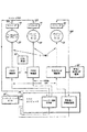
4 also shows a host computer (“CPU”) 95, a
[0029]
The operation of
[0030]
In this case, two control cards must be used. One card is a “shutter controller” for a shutter motor and a variable speed motor, and the other card is an “intermittent controller” or “servo motor controller” for an intermittent servo motor. Also, reference to “control system” shall include both controllers and all associated software.
[0031]
Initially, the control system operates in a 24-4 format with information derived from
[0032]
The rotation position of the
[0033]
With reference to FIGS. 7 and 8, the sequence of events can be summarized as follows.
[0034]
1. The control system is switched on and the
2. A default motion curve is loaded from the
3. The default film feed and frame advance speed are loaded from the
4). The
5. The intermittent servo motor controller continuously responds to one rotation of one indicator pulse generated by the
6). The
7). Step 5 continues without interruption until the
[0035]
As described above, the intermittent motion is connected so as to be interlocked with the
[0036]
When the intermittent sprocket 28 is driven, the
[0037]
With respect to the above sequence of events, the power and control system ("control system") described above functions as follows. Since the high response
[0038]
As the
[0039]
At the same time as the format change occurs, a change in the frame feed speed must also be performed. A
[0040]
In the three perforation format shown in FIG. 2, the frame centerline from left to right passes through the center of the film perforation. However, in the 4 perforation format shown in FIG. 1, the frame centerline bisects the spacing between the two
[0041]
It is important that the
[0042]
Since
[0043]
When another
[0044]
The
[0045]
When a new reel or platter of
[0046]
Furthermore, it is important that each motor can be equipped with a redundant encoder. This redundancy helps to ensure unhindered operation if there is a malfunction in one of the cooperating LEDs or photocells or sets of photodiodes. The switchable format projection system described above allows merchants to produce public prints in a modified format that eliminates waste. When doing so, the seller can save material and money without simultaneously degrading the quality of the video presented to the customer. The advantages of this method also exist beyond these initial savings. Since waste has been eliminated, the print is physically shorter and lighter. As a result, prints can be shipped at a lower cost, with full platters, and even ready for projection.
[0047]
Currently, the 100-minute film is 9,000 feet long, and is therefore shipped on a 2000 foot reel for weight reasons. These reels are spliced on a specific projector for the screen on which they are to be screened. This process is referred to as “loading” a movie. This must be done by a skilled individual, for example a projection technician. When a cinema administrator decides to move the print to another screen, the print typically must be “disassembled” and “reloaded” again. The reason is that the print is very heavy when placed on the platter and cannot be easily moved from the projector to the projector. However, in the new, more compact form made possible by the present invention, the same 100 minute film is only 6,750 feet long (using 3 perforation format film) or 5,625 feet ( 2.5 perforation format film). With this reduced length and weight, it is now possible to ship the film on a single pre-loaded reel and move the reel from the projector to the projector without “dismantling” and “reloading” the movie. Become.
[0048]
Another advantage of the
[0049]
(Industrial applicability)
From the above description, the control system identifies the format or frame rate from its trigger strip code and provides the appropriate commands for the various motors to operate in harmony in the newly defined operating mode. It will be appreciated that different or additional film formats can be fed over the
[0050]
This combination of features should be actively encouraged by producers and production managers with budgets ranging from under $ 1 million to $ 100 million. Eventually, there will be an ideal format available to everyone. Low budget production can enjoy the economic advantage of low public print costs. And high budget films can enjoy the increased screening value of larger and faster formats.
[0051]
This flexibility is also welcomed by film sellers and exhibitors, as they can have more choice in placing two (or more) film formats on the same platter of film. It will be. In this way, the cost and effort of selling and listing films is significantly reduced. In addition, little skill and training is required to perform switching between film formats for projection. Thus, this makes the system ideal for operation by relatively unskilled cinema workers.
[0052]
While particular forms of the invention have been illustrated and described, it will be apparent that various modifications can be made without departing from the spirit and scope of the invention. Accordingly, the invention is not intended to be limited except as by the appended claims.
[Brief description of the drawings]
FIG. 1 is a portion of one format film with 4 perforations in each frame interval.
FIG. 2 is a part of another format film with 3 perforations in the section of each frame.
FIG. 3 is a part of still another format film with 2.5 perforations in each frame section.
FIG. 4 is a perspective view showing all components of the film feeding system of the present invention, including a control component, with the projector portion separated for clarity.
FIG. 5 illustrates a multiple format film strip suitable for use in a film transport system.
FIG. 6 is a front view of a take-up sprocket and a digital optical encoder that are both driven by a servo motor.
7 is a front view of the optical encoder plate taken along line 7-7 in FIG. 6;
FIG. 8 is a schematic layout of the main components of the film feed system.
FIG. 9 is a flow diagram showing communication paths between major components of the film feed system.
Claims (22)
前記パーフォレーションに噛み合い、前記映写機を通ってフィルムを移動させる歯を有する複数のスプロケットと、
前記フィルムを、前記映写機の開口を通過して1コマ単位で移動させる断続送り機構と、
前記スプロケットを回転させ、前記断続送り機構を作動させる駆動要素と、
前記駆動要素を制御し、かつ、前記フィルムの各コマの区間に存在するパーフォレーションの数に関するフィルムのフォーマットに基づいて、および毎秒当たりのコマ数で表されるフィルムコマ送り速度に基づいて、前記スプロケットの回転速度と、前記断続送り機構の位置決めとを維持し、または変化させるコントローラと
を有するフィルム映写機運動機構。A film projector motion mechanism that sends a series of frames and a film having multiple perforations along both edges through a movie projector,
A plurality of sprockets having teeth that mesh with the perforations and move the film through the projector;
An intermittent feed mechanism for moving the film through the opening of the projector in units of one frame;
A driving element for rotating the sprocket and operating the intermittent feed mechanism;
Controls the driving element, and the film based on the format of the film on the number of perforations present in the interval of each frame, and based on the film frame feed speed represented by the number of frames per second, the sprocket A film projector motion mechanism comprising: a controller that maintains or changes the rotation speed of the motor and the positioning of the intermittent feed mechanism.
前記フィルム映写機運動機構が、シャッターを回転させる回転出力を有する第3のモータをさらに有する、請求項3記載のフィルム映写機運動機構。The drive element includes a first motor having a rotational output for rotating the pair of constant speed sprockets, and a second motor having a rotational output for intermittently rotating the intermittent sprockets ;
The film projector motion mechanism according to claim 3, further comprising a third motor having a rotational output for rotating the shutter.
前記トリガー信号は、前記映写機中のフィルムが、各コマの区間にあるフィルム上のパーフォレーションの数が第1の所定数であるフォーマットから、各コマの区間にあるフィルム上のパーフォレーションの数が第2の所定数であるフォーマットへ変化した時を示す、
請求項5に記載のフィルム映写機運動機構。The controller controls and regulates the first and second motors, and outputs the outputs of the first and second motors, and thus the rotational speed of the pair of sprockets and the positioning of the intermittent sprockets, respectively. In response to a trigger signal that changes to
In the trigger signal, the film in the projector has a format in which the number of perforations on the film in each frame section is the first predetermined number, and the number of perforations on the film in each frame section is the second. Indicates when the format has changed to a predetermined number of
The film projector motion mechanism according to claim 5.
前記フィルム映写機運動機構が、シャッターを回転させる回転出力を有する第3のモータをさらに有する、
請求項12に記載のフィルム映写機運動機構。The drive element includes a first motor having a rotational output for rotating the pair of constant speed sprockets, and a second motor having a rotational output for operating the intermittent feed mechanism or a reciprocating motion output ;
The film projector motion mechanism further comprises a third motor having a rotational output for rotating the shutter;
The film projector motion mechanism according to claim 12 .
前記1対の定速度スプロケットを回転させる回転出力を有する第1のモータと、
前記断続送り機構と前記シャッターとを作動させる回転出力または往復運動出力を有する第2のモータと、
を有する、請求項12に記載のフィルム映写機運動機構。The drive element is
A first motor having a rotational output for rotating the pair of constant speed sprockets;
A second motor having a rotational output or a reciprocating output for operating the intermittent feed mechanism and the shutter;
The film projector motion mechanism of claim 12 , comprising:
前記パーフォレーションに噛み合って前記映写機の開口を通過して1コマ単位で前記フィルムを送る断続送り機構と、
それぞれ前記開口と前記断続送り機構との各側にあって、前記パーフォレーションと噛み合い、前記断続送り機構と協働して前記映写機を通ってフィルムを送る歯を有する1対の定速度スプロケットと、
前記1対の定速度スプロケットを回転させる回転出力をもつ第1のモータと、
前記断続送り機構を作動させる、回転出力または往復運動出力を有する第2のモータと、
シャッターを回転させる回転出力を有する第3のモータと、
前記第1のモータの回転出力を制御、かつ調整する第1のコントローラであって、前記映写機のフィルムが、各コマの区間にあるフィルム上のパーフォレーションの数が第1の所定数である第1のフィルムフォーマットから、各コマの区間にあるフィルム上のパーフォレーションの数が第2の所定数である第2のフィルムフォーマットへ変化すると前記1対の定速度スプロケットの回転速度を変化させ、または維持するために、前記映写機の動作を実質的に中断しないで前記第1のモータの回転出力を変化させ、または、維持し、さらに、前記第3のモータを制御、かつ調整し、前記第3のモータの出力、従って、前記第3のモータの回転速度を変化させるトリガー信号に応答する第1のコントローラと、
前記トリガー信号に応答して、第1の割り出しフィルム送りを実行するために前記第2のモータの出力を制御し、前記第1の割り出しフィルム送りの長さは、送り出されるフィルムのフォーマットと到来するフィルムのフォーマットとのコマ高さによって定められ、後続のフィルム送りの出力は、到来するフォーマットのコマの高さに対応する長さをもつ第2のコントローラと、
を有し、
前記トリガー信号は、前記映写機内のフィルムが第1の所定のコマ送り速度で送られるモードから、該フィルムが第2の所定のコマ送り速度で送られるモードへ、該フィルムが変化した時を示す、
フィルム映写機運動機構。A film projector motion mechanism in a motion picture film projector that sends a film having a series of frames with images and a plurality of perforations along both edges,
An intermittent feed mechanism that meshes with the perforation and passes the opening of the projector to send the film in units of one frame;
A pair of constant speed sprockets each having a tooth on each side of the opening and the intermittent feed mechanism, meshing with the perforations and cooperating with the intermittent feed mechanism to feed the film through the projector;
A first motor having a rotational output for rotating the pair of constant speed sprockets;
A second motor having a rotational output or a reciprocating output for operating the intermittent feed mechanism;
A third motor having a rotational output for rotating the shutter;
A first controller that controls and adjusts the rotational output of the first motor, wherein the film of the projector has a first predetermined number of perforations on the film in each frame section. When the number of perforations on the film in each frame section is changed to the second film format having the second predetermined number, the rotational speed of the pair of constant speed sprockets is changed or maintained. Therefore, the rotation output of the first motor is changed or maintained without substantially interrupting the operation of the projector , and the third motor is controlled and adjusted. A first controller responsive to a trigger signal for changing the output of the third motor, and thus the rotational speed of the third motor
In response to the trigger signal, control the output of the second motor to perform a first indexed film feed, the length of the first indexed film feed coming with the format of the film being fed out. A second controller having a length corresponding to the frame height of the incoming format, the output of the subsequent film advance being determined by the frame height of the film format;
Have
The trigger signal indicates when the film has changed from a mode in which the film in the projector is fed at a first predetermined frame rate to a mode in which the film is fed at a second predetermined frame rate. The
Film projector motion mechanism.
前記映写機を通ってフィルムを送る複数のスプロケットおよび1つの断続運動装置と、
選択された速度で前記スプロケットを回転させ、前記断続運動装置を作動させ、かつ、前記映写機内の開口を通過して1フレーム単位で、断続的にフィルムを位置決めするモータ手段と、
前記モータ手段を制御し、かつ、フィルム上の各コマの区間にあるパーフォレーションの数に関するフィルムのフォーマットと、毎秒あたりのコマ数で表されるフィルムコマ送り速度に基づいて、前記断続運動装置の運動と、前記スプロケットの回転速度と、前記フィルムの送りを変化させ、または、維持するコントロール手段と、
前記モータ手段を制御し、到来するフィルムのフォーマットの適正なコマ送りを生成するために、送り出されるフィルムフォーマットと到来するフィルムフォーマットのコマ高さに基づいて、最初の割り出し運動を行うコントロール手段とを有する
フィルム映写機運動機構。A film projector motion mechanism having perforations along both edges and sending a film with a frame between the perforations through the projector;
A plurality of sprockets and an intermittent motion device for sending film through the projector;
Motor means for rotating the sprocket at a selected speed, activating the intermittent motion device, and intermittently positioning the film in one frame units through an opening in the projector;
The motion of the intermittent motion device controls the motor means and based on the film format relating to the number of perforations in each frame section on the film and the film frame feed speed represented by the number of frames per second. And control means for changing or maintaining the rotation speed of the sprocket and the feeding of the film,
Control means for controlling the motor means and performing an initial indexing motion based on the frame format of the outgoing film format and the incoming film format in order to generate an appropriate frame advance for the incoming film format. Have film projector motion mechanism.
前記フィルム上の各コマの区間にあるパーフォレーションの数に関するフィルムフォーマットを定め、
前記開口を通過する1秒当たりのコマ数で表されるフィルムコマ送り速度を定め、前記フィルムフォーマットに基づいて、および前記フィルムコマ送り速度に基づいて、前記スプロケットの回転速度および前記断続運動装置の運動を維持するか、または、変化させるように、前記駆動要素を制御する、
映写機を通ってフィルムを送る方法。Film rotates the plurality of sprockets Send, also provides a method of through projector having a drive element that drives the intermittent movement device for feeding the film by one frame basis by passing through the opening Send film,
Define the film format for the number of perforations in each frame section on the film,
A film frame feed speed represented by the number of frames per second passing through the opening is determined, and based on the film format and based on the film frame feed speed , the rotational speed of the sprocket and the intermittent motion device Controlling the drive element to maintain or change movement;
Sending film through a projector.
前記フィルム上の各コマの区間毎に測られるパーフォレーションの数で、到来するフィルムのコマ高さを決定し、
送り出されるフィルムのフォーマットのコマ高さと到来するフィルムのフォーマットのコマ高さに基づいて第1の割り出し運動を決定し、
前記開口を通過する1秒当たりのコマ数で表されるフィルムコマ送り速度を決定し、
前記フィルムフォーマットに基づいて前記第1のモータの回転出力を制御し、
前記第1の割り出し運動と、到来するフィルムのフォーマットと、前記フィルムコマ送り速度に基づいて、前記第2の駆動要素の出力を制御し、
前記フィルムのコマ送り速度に基づいて、前記第3のモータの出力を制御する、
映写機を通ってフィルムを送る方法。A pair of constant-speed sprockets that mesh with perforations on the film, and an intermittent motion device that passes the film one frame at a time through an opening in the projector to send the film at a uniform speed; One motor has a rotational output that rotates the constant speed sprocket, a second drive element has an output that positions the intermittent motion device, and a third motor has a rotational output that rotates the shutter. , A method of sending film through a projector,
The number of perforations measured for each frame interval on the film determines the frame height of the incoming film,
The first indexing motion is determined based on the frame height of the film format to be sent out and the frame height of the format of the incoming film,
Determining the film frame feed speed represented by the number of frames per second passing through the opening;
Controls the rotation output of the first motor based on the film format,
Said first and indexing motion, and format of the incoming film, based on the film frame feed speed, to control the output of the second drive element,
Based on the frame feed speed of the film, it controls the output of the third motor,
Sending film through a projector.
Applications Claiming Priority (3)
| Application Number | Priority Date | Filing Date | Title |
|---|---|---|---|
| US08/907,429 | 1997-08-07 | ||
| US08/907,429 US6019473A (en) | 1996-02-07 | 1997-08-07 | Switchable format film projection system |
| PCT/US1998/015902 WO1999008155A1 (en) | 1997-08-07 | 1998-07-30 | Switchable format film projection system |
Publications (3)
| Publication Number | Publication Date |
|---|---|
| JP2001512854A JP2001512854A (en) | 2001-08-28 |
| JP2001512854A5 JP2001512854A5 (en) | 2006-01-05 |
| JP4246377B2 true JP4246377B2 (en) | 2009-04-02 |
Family
ID=25424085
Family Applications (1)
| Application Number | Title | Priority Date | Filing Date |
|---|---|---|---|
| JP2000506565A Expired - Fee Related JP4246377B2 (en) | 1997-08-07 | 1998-07-30 | Format switchable film projection system |
Country Status (14)
| Country | Link |
|---|---|
| US (1) | US6019473A (en) |
| EP (1) | EP1002257B1 (en) |
| JP (1) | JP4246377B2 (en) |
| KR (1) | KR100579781B1 (en) |
| CN (1) | CN100456127C (en) |
| AT (1) | ATE281661T1 (en) |
| AU (1) | AU757754B2 (en) |
| CA (1) | CA2298708C (en) |
| DE (1) | DE69827391T2 (en) |
| ES (1) | ES2232003T3 (en) |
| HK (1) | HK1030991A1 (en) |
| IL (1) | IL134208A (en) |
| RU (1) | RU2218586C2 (en) |
| WO (1) | WO1999008155A1 (en) |
Families Citing this family (10)
| Publication number | Priority date | Publication date | Assignee | Title |
|---|---|---|---|---|
| US20010043310A1 (en) * | 1996-02-07 | 2001-11-22 | Goodhill Dean K. | Switchable format film projection system |
| JPH11352590A (en) * | 1998-06-09 | 1999-12-24 | Sony Corp | Device and method for positioning film |
| US6529600B1 (en) * | 1998-06-25 | 2003-03-04 | Koninklijke Philips Electronics N.V. | Method and device for preventing piracy of video material from theater screens |
| DE10327771A1 (en) * | 2003-06-17 | 2005-01-05 | Arnold & Richter Cine Technik Gmbh & Co Betriebs Kg | Device for transporting a motion picture film |
| US20060072073A1 (en) * | 2003-08-28 | 2006-04-06 | Weisgerber Robert C | Method for producing and exhibiting three-dimensional motion pictures from a single strip of motion picture film |
| CA2611009A1 (en) * | 2005-06-08 | 2006-12-14 | Dean K. Goodhill | Method and apparatus for inhibiting the piracy of motion pictures |
| CA2636858C (en) * | 2006-01-27 | 2015-11-24 | Imax Corporation | Methods and systems for digitally re-mastering of 2d and 3d motion pictures for exhibition with enhanced visual quality |
| CA2653815C (en) | 2006-06-23 | 2016-10-04 | Imax Corporation | Methods and systems for converting 2d motion pictures for stereoscopic 3d exhibition |
| MX2014003488A (en) * | 2011-09-26 | 2014-07-22 | Koninkl Philips Nv | Imaging system rotating gantry and subject support motion control. |
| US9275603B2 (en) * | 2012-04-23 | 2016-03-01 | Intel Corporation | Driving displays at cinematic frame rates |
Family Cites Families (34)
| Publication number | Priority date | Publication date | Assignee | Title |
|---|---|---|---|---|
| US1318610A (en) * | 1919-10-14 | sereinsky | ||
| US1921494A (en) * | 1927-04-21 | 1933-08-08 | Wildhaber Ernest | Method of producing audible pictures |
| US1835743A (en) * | 1929-08-14 | 1931-12-08 | Bell Telephone Labor Inc | Sound picture system |
| US1999754A (en) * | 1932-04-22 | 1935-04-30 | Arthur M Hyde | Recording and projecting sound on film apparatus |
| US2079572A (en) * | 1933-01-03 | 1937-05-04 | Ripley Corp | Method of and apparatus for recording sound on the edge of film |
| US3285087A (en) * | 1963-07-24 | 1966-11-15 | Panopix Res Inc | Variable speed drive sprocket |
| US3565521A (en) * | 1968-11-26 | 1971-02-23 | Lawrence W Butler | Variable size film framing and transport system |
| JPS5016931B1 (en) * | 1970-03-03 | 1975-06-17 | ||
| US3819258A (en) * | 1972-09-20 | 1974-06-25 | Scripps Clemans | Film framing and transport system |
| US3865738A (en) * | 1974-01-21 | 1975-02-11 | Miklos Lente | Method of making motion pictures |
| DE2558747A1 (en) * | 1975-12-24 | 1977-07-07 | Rollei Werke Franke Heidecke | SMALL TONE FILM PROJECTOR |
| US4143951A (en) * | 1975-12-27 | 1979-03-13 | Canon Kabushiki Kaisha | Cine-projector |
| US4150886A (en) * | 1976-08-26 | 1979-04-24 | Airborne Mfg. Co. | Motion picture projector system |
| US4105311A (en) * | 1976-11-08 | 1978-08-08 | Eprad Incorporated | Film transport system |
| US4360254A (en) * | 1980-03-27 | 1982-11-23 | Mangum-Sickles Industries, Inc. | Camera having stepper motor driven film transport/registration sprocket |
| US4437742A (en) * | 1980-10-09 | 1984-03-20 | Minolta Camera Kabushiki Kaisha | Camera capable of automatically responding to data coded on film |
| US4678298A (en) * | 1982-11-22 | 1987-07-07 | Zoran Perisic | Method and apparatus for three-dimensional photography |
| US4702577A (en) * | 1984-08-17 | 1987-10-27 | Dedo Weigert Film Gmbh | Film transport device |
| US4697896A (en) * | 1986-09-30 | 1987-10-06 | Showscan Film Corporation | Electronic projector |
| FR2622707A1 (en) * | 1987-10-30 | 1989-05-05 | Aaton Sa | METHOD FOR REGISTERING, ON THE MARGINAL PART OF A PERFORATED CINEMATOGRAPHIC FILM, CODE INFORMATION |
| US4900293A (en) * | 1989-05-26 | 1990-02-13 | Mclendon Donald C | 4:3 perf conversion sprocket |
| CN2049370U (en) * | 1989-06-24 | 1989-12-13 | 张玉申 | Automatic staggered frame setting apparatus for cine-projector |
| US5096286A (en) * | 1990-03-07 | 1992-03-17 | Weisgerber Robert C | Method for transitioning between two different frame rates during a showing of a single motion picture film |
| US5218388A (en) * | 1991-06-21 | 1993-06-08 | Purdy William H | Film monitor for use in automating movie theater operation |
| EP0616700A4 (en) * | 1991-12-12 | 1995-03-29 | United Artists Theatre Circuit | Motion picture system for economical replication, consolidation, duplication and exhibition of wide screen formats. |
| US5739895A (en) * | 1991-12-12 | 1998-04-14 | United Artists Theatre Circuit, Inc. | Film saving system |
| US5543869A (en) * | 1991-12-12 | 1996-08-06 | Vetter; Richard | Frame registration |
| US5312304A (en) * | 1992-11-18 | 1994-05-17 | United Artists Entertainment | Convertible sprocket for motion picture film |
| JPH06208179A (en) * | 1993-01-08 | 1994-07-26 | Sony Corp | Cinematographic film and its reproducing device |
| US5341182A (en) * | 1993-01-14 | 1994-08-23 | Pioneer Technology Corporation | Motion picture projection apparatus |
| US5539527A (en) * | 1993-03-11 | 1996-07-23 | Matsushita Electric Industrial Co., Ltd. | System for non-linear video editing |
| US5450140A (en) * | 1993-04-21 | 1995-09-12 | Washino; Kinya | Personal-computer-based video production system |
| US5506639A (en) * | 1993-05-07 | 1996-04-09 | Frazen; Nancy E. | Method and apparatus for editing motion picture film and synchronized sound |
| US5946076A (en) * | 1996-02-07 | 1999-08-31 | Maxivision Cinema Technology | Switchable pulldown film projection system |
-
1997
- 1997-08-07 US US08/907,429 patent/US6019473A/en not_active Expired - Lifetime
-
1998
- 1998-07-30 RU RU2000101829/28A patent/RU2218586C2/en not_active IP Right Cessation
- 1998-07-30 KR KR1020007001289A patent/KR100579781B1/en not_active IP Right Cessation
- 1998-07-30 DE DE69827391T patent/DE69827391T2/en not_active Expired - Lifetime
- 1998-07-30 CN CNB988079364A patent/CN100456127C/en not_active Expired - Fee Related
- 1998-07-30 IL IL13420898A patent/IL134208A/en not_active IP Right Cessation
- 1998-07-30 ES ES98939134T patent/ES2232003T3/en not_active Expired - Lifetime
- 1998-07-30 AT AT98939134T patent/ATE281661T1/en not_active IP Right Cessation
- 1998-07-30 AU AU87624/98A patent/AU757754B2/en not_active Ceased
- 1998-07-30 EP EP98939134A patent/EP1002257B1/en not_active Expired - Lifetime
- 1998-07-30 WO PCT/US1998/015902 patent/WO1999008155A1/en active IP Right Grant
- 1998-07-30 JP JP2000506565A patent/JP4246377B2/en not_active Expired - Fee Related
- 1998-07-30 CA CA002298708A patent/CA2298708C/en not_active Expired - Fee Related
-
2001
- 2001-03-06 HK HK01101594.7A patent/HK1030991A1/en not_active IP Right Cessation
Also Published As
| Publication number | Publication date |
|---|---|
| JP2001512854A (en) | 2001-08-28 |
| CA2298708C (en) | 2007-10-23 |
| DE69827391D1 (en) | 2004-12-09 |
| ATE281661T1 (en) | 2004-11-15 |
| DE69827391T2 (en) | 2005-10-27 |
| KR100579781B1 (en) | 2006-05-12 |
| AU757754B2 (en) | 2003-03-06 |
| RU2218586C2 (en) | 2003-12-10 |
| CA2298708A1 (en) | 1999-02-18 |
| AU8762498A (en) | 1999-03-01 |
| CN1265747A (en) | 2000-09-06 |
| IL134208A0 (en) | 2001-04-30 |
| HK1030991A1 (en) | 2001-05-25 |
| CN100456127C (en) | 2009-01-28 |
| EP1002257B1 (en) | 2004-11-03 |
| WO1999008155A1 (en) | 1999-02-18 |
| EP1002257A1 (en) | 2000-05-24 |
| ES2232003T3 (en) | 2005-05-16 |
| KR20010022694A (en) | 2001-03-26 |
| IL134208A (en) | 2004-05-12 |
| US6019473A (en) | 2000-02-01 |
Similar Documents
| Publication | Publication Date | Title |
|---|---|---|
| JP4246377B2 (en) | Format switchable film projection system | |
| JPS6159497B2 (en) | ||
| EP0616700A1 (en) | Motion picture system for economical replication, consolidation, duplication and exhibition of wide screen formats | |
| US20020021412A1 (en) | Method of making motion picture release-print film | |
| US20060061732A1 (en) | Switchable format film projection system | |
| RU2207610C2 (en) | Switchable film-movement projection system | |
| AU768025C (en) | Method of making motion picture release-print film | |
| WO1993006520A1 (en) | Method and apparatus for producing and displaying a motion picture | |
| MXPA00001213A (en) | Switchable format film projection system | |
| US4188099A (en) | Image projection apparatus with sustained image exposure | |
| EP0191559A1 (en) | A system for exhibiting motion pictures | |
| AU666909C (en) | Motion picture system | |
| US3124995A (en) | hennessey | |
| Stern | A Broadcast Television Film-Chain Projector | |
| WO2006000886A1 (en) | Synchronization check systems and methods for film projectors |
Legal Events
| Date | Code | Title | Description |
|---|---|---|---|
| RD04 | Notification of resignation of power of attorney |
Free format text: JAPANESE INTERMEDIATE CODE: A7424 Effective date: 20050314 |
|
| A521 | Request for written amendment filed |
Free format text: JAPANESE INTERMEDIATE CODE: A523 Effective date: 20050727 |
|
| A621 | Written request for application examination |
Free format text: JAPANESE INTERMEDIATE CODE: A621 Effective date: 20050727 |
|
| RD03 | Notification of appointment of power of attorney |
Free format text: JAPANESE INTERMEDIATE CODE: A7423 Effective date: 20050727 |
|
| A131 | Notification of reasons for refusal |
Free format text: JAPANESE INTERMEDIATE CODE: A131 Effective date: 20080514 |
|
| A601 | Written request for extension of time |
Free format text: JAPANESE INTERMEDIATE CODE: A601 Effective date: 20080718 |
|
| A602 | Written permission of extension of time |
Free format text: JAPANESE INTERMEDIATE CODE: A602 Effective date: 20080808 |
|
| A601 | Written request for extension of time |
Free format text: JAPANESE INTERMEDIATE CODE: A601 Effective date: 20080904 |
|
| A602 | Written permission of extension of time |
Free format text: JAPANESE INTERMEDIATE CODE: A602 Effective date: 20080916 |
|
| A601 | Written request for extension of time |
Free format text: JAPANESE INTERMEDIATE CODE: A601 Effective date: 20081009 |
|
| A521 | Request for written amendment filed |
Free format text: JAPANESE INTERMEDIATE CODE: A523 Effective date: 20081022 |
|
| A602 | Written permission of extension of time |
Free format text: JAPANESE INTERMEDIATE CODE: A602 Effective date: 20081029 |
|
| A521 | Request for written amendment filed |
Free format text: JAPANESE INTERMEDIATE CODE: A523 Effective date: 20081114 |
|
| TRDD | Decision of grant or rejection written | ||
| A01 | Written decision to grant a patent or to grant a registration (utility model) |
Free format text: JAPANESE INTERMEDIATE CODE: A01 Effective date: 20081210 |
|
| A01 | Written decision to grant a patent or to grant a registration (utility model) |
Free format text: JAPANESE INTERMEDIATE CODE: A01 |
|
| A61 | First payment of annual fees (during grant procedure) |
Free format text: JAPANESE INTERMEDIATE CODE: A61 Effective date: 20090108 |
|
| R150 | Certificate of patent or registration of utility model |
Free format text: JAPANESE INTERMEDIATE CODE: R150 |
|
| FPAY | Renewal fee payment (event date is renewal date of database) |
Free format text: PAYMENT UNTIL: 20120116 Year of fee payment: 3 |
|
| FPAY | Renewal fee payment (event date is renewal date of database) |
Free format text: PAYMENT UNTIL: 20130116 Year of fee payment: 4 |
|
| LAPS | Cancellation because of no payment of annual fees |