CN100455997C - Device and method for measuring flow process from hillslope runoff plots - Google Patents
Device and method for measuring flow process from hillslope runoff plots Download PDFInfo
- Publication number
- CN100455997C CN100455997C CNB2006101133862A CN200610113386A CN100455997C CN 100455997 C CN100455997 C CN 100455997C CN B2006101133862 A CNB2006101133862 A CN B2006101133862A CN 200610113386 A CN200610113386 A CN 200610113386A CN 100455997 C CN100455997 C CN 100455997C
- Authority
- CN
- China
- Prior art keywords
- pulling force
- hillslope
- flow
- value
- flow process
- Prior art date
- Legal status (The legal status is an assumption and is not a legal conclusion. Google has not performed a legal analysis and makes no representation as to the accuracy of the status listed.)
- Expired - Fee Related
Links
Images
Landscapes
- Measuring Volume Flow (AREA)
Abstract
The invention discloses a measuring slope runoff plot flow process device and method, which includes: a pull force sensor, a stand, a bearing tube, at least one rigid rope, flexible telescopic tube, the first hoop, the second hoop, a diversion pipe, a fixed part, drainage device. The method includes the following steps: 1) parameter calibration; according to the formula Q=f(F)=alphaF3/2 to calibrate, obtaining alpha; in which Q denotes flow, F denotes pull force; 2) position the device to begin flow measurement, and record the pull force value F of the pull force sensor in all time; 3) according to the pull force F, compute the flow value Q in all time with formula Q=f(F)=alphaF3/2 and the parameter alpha obtained by the calibration in step 1. The invention has the advantages of accurate observation, automatic observation, time-save and effort-save.
Description
Technical field
The present invention relates to a kind of apparatus and method of measuring flow process from hillslope runoff plots.
Background technology
The research of the soil erosion and domatic water regime is usually by the observation of the slope runoff under rainmaking or the natural precipitation condition, yet current contain the difficulty that husky characteristics have increased runoff observation.Slope runoff has head low (no setting-out stream), the characteristics of flow little (having only several liters/second usually) in addition.Therefore, the flow measurement device that is widely used in channel, river course is subjected to the restriction of sensitivity and degree of accuracy and is difficult to using.
Owing to be subjected to the singularity and the limitation of complexity of field condition environment, water collecting basin method and porous shunting are generally adopted in slope runoff cell flow observation both at home and abroad at present, as document 1: " World MeteorologicalOrganization.Guilde to meteorological instrument and observing practices.; 1961; W.M.O-No.8TP3. " and document 2: " Pinson; W T; Yoder; D C, Buchanan, J R, Wright, W C, Wilkerson, JB.Design and Evaluation of an Improved Flow Divider forSampling Runoff Plots.Applied Engineering in Agriculture[J], 2004,20:433-438. " in disclosed technology, its something in common is all to need to artificially collect runoff, manual measurement.Therefore operating process is loaded down with trivial details, wastes time and energy, and it is bigger that measurement result is influenced by human factor, and can not implementation procedure observation.In addition, the critical defect of these two kinds of methods is to be easy to generate overflow under the heavy rain situation, thereby usually causes the observation data disappearance.
In the process of rainfall erosion, all there are randomness in rainfall intensity and rainfall duration, and the runoff process is for understanding erosion mechanism and overland flow hydrodynamic force rule is very important.In order to realize the process observation of runoff, scholar both domestic and external has carried out a large amount of correlative studys, wherein the flowmeter based on the tipping bucket method is typical a kind of flowmeter, as document 3: " Cao Jiansheng; Liu Changming; Zhang Wanjun. based on the automatic measuring technology and the application [J] thereof of tipping bucket method. water conservancy and hydropower scientific advance; 2005.25 (2): 49-52. ", document 4: " Barfield B J; M C Hirschi.Tipping bucket flow measurements on erosion plots[J] .Transaction of ofthe ASAE.1986; 29 (6): 1600-1604. " and document 5: disclosed technology in " Ahmed A H, Khan and Chin K is and Calibration of Tipping Bucket System for Field Runoff andSediment Quantification.Journal of Soil and Water Conservation52 (6): 437-443. O.1997.Design ".The principle of this method has been widely used in rain gage, promptly utilize mechanical measurement element (being generally symmetrical expression tipping bucket chamber) that fluid continuously is divided into single known volume part, repeatedly be full of one by one and the number of times that discharges this volume segment fluid flow is measured fluid volume total amount and process according to measuring chamber.But slope runoff is the concentrated flow that is different from rainfall observation, and intensity is relatively large, the amplification during the error that inertia force influence produces can be observed than rainfall, and do not have to solve problem how to consider silt content in the prior art.
Therefore, the apparatus and method that just need a kind of new measurement flow process from hillslope runoff plots.
Summary of the invention
The objective of the invention is to overcome above-mentioned the deficiencies in the prior art, solve the shortcoming that open-air manually-operated is wasted time and energy, precision is low, and solve the observation problem of silt carrying flow, thereby a kind of apparatus and method of measuring flow process from hillslope runoff plots are provided.
In order to achieve the above object, the technical scheme taked of the present invention is as follows:
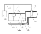
A kind of device of measuring flow process from hillslope runoff plots as shown in Figure 1, 2, comprising:
One pulling force sensor 1, this pulling force sensor 1 is fixed on the top of a support 10;
One bearing tube 2, this bearing tube 2 is connected with described pulling force sensor 1 by at least one rigidity rope 7;
One flexible telescopic tube 3, this flexible telescopic tube 3 is communicated with described bearing tube 2 and a water conservancy diversion pipe fitting 4 respectively by first clip 8 and second clip 9;
One drainage system 5, this drainage system inlet is trapezoidal contraction structure, the double-deck drop structure that the drainage system outlet is designed to have the drop function, drainage system 5 is communicated with described water conservancy diversion pipe fitting 4 by welding or bonding mode;
The pulling force point of described pulling force sensor 1 be positioned at a bearing tube 2 directly over;
Described water conservancy diversion pipe fitting 4 is fixed on the described support 10 by fixed part 12.
Described trapezoidal contraction structure promptly inwardly shrinks gradually from the vertical trapezoid cross section of porch and reduces.
Further, also comprise a data presentation device 11, this data presentation device 11 is connected with pulling force sensor 1 by lead 13, is used to show pulling force output.
Further, also be included in the described inlet drainage system 5 a silt sensor 6 is installed, this silt sensor 6 is connected with data presentation device 11, thereby the precision correction is carried out in silt carrying flow, is applicable to the bigger area of silt content in the rainfall runoff.
Further, described water conservancy diversion pipe fitting 4 and described inlet drainage system 5 become one.
Further, this device comprises two described rigidity ropes, two rigidity ropes respectively with an end the axis symmetria bilateralis of described bearing tube 2 be fixed on the bearing tube outside surface, the other end of two rigidity ropes is fixed on the stress point of pulling force sensor 1 jointly, thereby reduce rocking of bearing tube, improve observation quality.
Further, described data presentation device 11 comprises data acquisition unit and data processor, and this data processor calculates the pulling force sensor data that the data collector collects, and shows data on flows.
Further, described data presentation device 11 real-time video datas, figure, or data and figure.
In conjunction with said apparatus, a kind of method of measuring flow process from hillslope runoff plots comprises the steps:
1) parameter calibration: according to formula
Demarcate, obtain α; Wherein Q represents flow, and F represents pulling force;
2) device that will measure flow process from hillslope runoff plots places and measures ground beginning flow measurement, writes down each pulling force sensor value of thrust F constantly;
3) according to value of thrust F formula
Calculate each flow value Q constantly with the parameter alpha that demarcation in the step 1) is tried to achieve.
In the said method step, further, in the bigger area of runoff silt content, sediment concentration can have certain influence to observed result, more accurate if desired runoff observed reading, then step 2) also comprise and write down each sediment concentration value c of value of thrust correspondence constantly; And the formula in the step 3) replaces to following formula:
Compared with prior art, the invention has the advantages that:
1) the present invention can realize the accurate surveying of flow process from hillslope runoff plots;
2) experimental provision is easy, need not water, but also can easily realize observation automatically in real time;
3) can carry out the correction that silt content influences to the big current observation result of silt content;
4) precision height of the present invention is durable and time saving and energy saving, for a large amount of time, man power and material are saved in related personnel's field trial and soil erosion field monitoring work.
Description of drawings
Fig. 1 represents the structure composition sectional view of slope runoff cell flow measurement mechanism of the present invention;
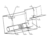
Fig. 2 represents the three-dimensional cross-sectional schematic of apparatus of the present invention core texture;
Fig. 3 represents apparatus of the present invention bearing tube force diagram;
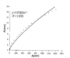
Fig. 4 represents the numerical relation of the hydraulic radius R and the water-carrying section A of corresponding same water surface elevation in apparatus of the present invention bearing tube;
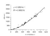
Fig. 5 represents value of thrust and actual flow regretional analysis figure;
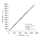
Fig. 6 represents the comparative analysis of artificial observation run-off and Instrument observation value; Wherein dotted line represents not consider the situation of silt content influence, and solid line is represented the situation through the silt content correction;
Fig. 7 represents that silt content causes the relative error of flow observation.
Embodiment
Below in conjunction with the drawings and specific embodiments the present invention is described in further detail:
3-7 describes principle of the present invention and verification experimental verification result at first in conjunction with the accompanying drawings.
As shown in Figure 3, act on the power and the momentum of the tube portion of weighing,, have according to stressed and momentum balance:
In the formula: F-acts on the pulling force on the pulling force sensor, unit: kilogram (kg);
The weigh gradient (1 ° of ≈) of pipe of θ-be;
The friction coefficient of f-flow action on the pipe of weighing;
W-is the gravity of water body in the pipe of weighing, unit: kg;
The distance of δ-tensile force f and gravity W active line, unit: rice (m), (in fact very I is to ignore);
L-is the length of pipe of weighing, unit: m;
ε
1, ε-be the respectively displacement that pipe causes at the miniature deformation of pulling force point A and strong point B of weighing, unit: rice (m);
Pipe is very little at the deformation quantity of pulling force point A and strong point B because weigh, and the power that acts on these two points can be expressed as with the Hooke theorem: F
S=ε
1K
1, F
S=ε K, K in the formula, K1 be elasticity coefficient (kg/m) so. formula (1.1-1.3) can be expressed as:
K
1ε
1cosθ+Kε=W+F
t?sinθ-F
t?sinθ
F
t=F
f+F
stgθ (2.1-2.3)
Flexible flexible pipe connects can make the pipe of weighing rotate flexibly to a certain extent, is hinged so the connection of flexible pipe can be regarded as, and Ms ≈ 0 is so just arranged.Suppose ε
1≈ ε obtains (2.3) substitution (2.2):
ε(K
1?cosθ+K)=W-F
stgθsinθ≈W (3.1)
And 1 ° of θ ≈, can think that tg θ sin θ ≈ 0 following formula can be deformed into:
Bringing F=ε K into can obtain:
For flexible plastic pipe, K
1<<K, and when 1 ° of θ ≈, fsin θ<<1.So,, act between the gravity of the water on the pipe of weighing and the value of thrust and can be approximated to be linear relationship in any definite moment.
The density of water is 1000 kilograms per cubic meter (kg/m3) during with very little 4 ℃ of variation of temperature scope; 998.2kg/m in the time of 20 ℃
3≈ 1000kg/m
3, in application of practical project, the density of water is commonly considered as a constant.Therefore, do not considering that sediment concentration is under the situation of clear water, having following relation to set up:
F∝W?W∝V (4.2)
In the formula: V is the volume of Guan Zhongshui of weighing particular moment, L; Thereby can release following relation:
F∝V (4.3)
Following formula shows: the pulling force that acts on the pulling force sensor is determined by flow.Otherwise if this relation exists, flow observation just can realize that its funtcional relationship is as follows by the observation of value of thrust:
V=f
-1(F) (4.4)
At sediment concentration is 0kg/m
3Be under the situation of clear water, can regard open-channel constant stream as by the current of the pipe of weighing.Chezy formula (5) and full peaceful formula (6) can obtain the flow formula (7) of open channel uniform flow
In the formula: Q-flow, L/s;
The i-hydraulic gradient, m/m;
The A-discharge area, m
2
C-thanks just coefficient, m
1/2/ s;
The R-hydraulic radius, m;
The completely peaceful coefficient of n-, dimensionless;
In high-line conduit, as document: " Wu Chigong. hydraulics (first volume) [M]. Beijing: Higher Education Publishing House, 1982.240 " in disclosed, being calculated as follows of hydraulic radius:

In the formula, d is a pipe diameter, unit: m; φ is the central angle of water surface string.
Satisfying under the prerequisite of practical application, in order to simplify the relation of (8) middle Q and R, to internal diameter is the pipe of weighing of 60mm, pairing R of different water surface elevations and A are carried out regretional analysis (Fig. 4) in water surface elevation is no more than the scope of pipeline radius, be better correlation formula (9) related coefficient between the numerical value of R and A and can arrive 0.97.
With formula (9) substitution formula (7):
Pipe is relatively short and can be approximately constant along the water (flow) direction section because weigh, and therefore can think V=Al, and substitution formula (10) then has:
For physical arrangement, material, the runoff observation device that size is set the volume V of the water in the formula in the pipe of weighing, all is a constant, so Q is function such as the formula (12) that contains unitary variant V
The substitution formula (12) that concerns of formula (4.2) is got:
More than be that sediment concentration is 0 to be the situation of clear water.Under the situation of silt carrying flow, the water of corresponding same weight, its volume is less than the situation of clear water.Therefore, the value of thrust that certain is corresponding identical constantly, the actual flow of silt carrying flow is less than the flow of clear water.If the silt content of current is c (kg/m3), actual flow is Qc (m3/s), and then the relation with the flow of clear water situation can be expressed as follows:
Qρ
w=ρ
wf(F) (14.1)
And:
Merge abbreviation (14.1) and (14.2):
In the formula: the density of ρ w=1000kg/m3 water; ρ s=2650kg/m3 is a dry ground density. above formula can further be deformed into:
Above formula shows, just can realize the observation of silt carrying flow runoff as long as the supporting sediment charge sensor of pulling force sensor obtains the runoff silt content simultaneously.
Make the device of measurement flow process from hillslope runoff plots of the present invention with reference to Fig. 1, the conventional products that pulling force sensor 1 adopts market to sell, such as CZL-1R type LOAD CELLS, the range of pulling force sensor 1 is 1000g, precision is 0.1g; The internal diameter of bearing tube 2 is 60mm, length is 26mm, be suspended under the pulling force sensor 1 with two wire rope 7, for strengthen stability reduce current by the time weigh the rocking of pipe, two stress point and the pulling force sensor stress point of two wire rope on bearing tube is isoceles triangle and distributes.Sediment concentration sensor 6 adopts conventional products that sell in market, or adopt prior art the sediment concentration sensor as " Wang Hui, Lei Tingwu, Zhao Jun; Liu Qingkun. slope runoff amount and silt content dynamic measurement system [J]. agricultural mechanical journal, 2005.36 (1): 79-82. " in disclosed technology.Data acquisition unit 11 carries out wire communication by lead and pulling force sensor 1, silt sensor 6, and data acquisition unit 11 is a base unit with 1/3 gram (g), therefore has 1/3000 resolution.
Pulling force sensor 1 is connected realization with the data transmission of data acquisition unit 11 by common wiring 13 with sediment concentration sensor 6; The processing of shell 10 adopts 25 * 4mm angle aluminium to do framework, and the iron sheet that outsourcing 1mm is thick, apparent size are 500mm * 200mm * 200mm; The rubber bellows that flexible telescopic tube 3 adopts market to sell, the internal diameter of corrugated tube is 60mm with weighing pipe among the embodiment, length is 12mm; Water conservancy diversion pipe fitting 4 is used in bearing tube 2 identical material and models, i.e. 60mmm internal diameter pvc pipe, and length is 12mm.Inlet drainage system 5 adopts the thick iron sheet typing weldering system of 1mm among the embodiment.Drainage system 5 adopts anchoring to add splicing with being connected of water conservancy diversion pipe fitting 4.
The inlet of drainage system 5 is trapezoidal contraction structure; The double-deck drop structure that outlet is designed to have drop function has about interconnected two-layerly, and the water of drainage drops into lower floor from the upper strata; Drainage system 5 is communicated with described water conservancy diversion pipe fitting 4, and trapezoidal contraction structure promptly inwardly shrinks gradually from the vertical trapezoid cross section of porch and reduces, and the benefit of making is to help guiding current like this.
The raw data of pulling force sensor 1 can be gathered, store to data acquisition unit 11 automatically under the control of software program, and can be converted into flow value to the pulling force data that collects by software program, those skilled in the art can be competent at control for data acquisition unit 11 according to the method for introducing below.
Its measuring method is following steps:
1) calibrating parameters;
Under the condition of clear water, by outflow test, artificial and instrument is observed flow value and value of thrust respectively, the result is compared and match, and compare with the model of theoretical derivation.In the implementation process, adopt the water tank volume of Ma Shi bottle principle to be about 1m
3The constant voltage current are provided, and water pipe is guided to the instrument porch with water; At the terminal mounted valve of aqueduct, the manual control valve is a flow even variation from big to small more from small to large, and flow is in 0-3000ml/s and 3000-0ml/s range regulation among the embodiment; Manually in the sampling of the exit of instrument, with the standard value of volumetric method calculated flow rate as flow observation; The corresponding value of thrust constantly that the reading and recording data acquisition unit collects in the time of hand sampling.
As embodiment, 5 of artificial observation employings herein repeat to be averaged.
For the flow value of artificial observation and corresponding value of thrust, see Fig. 6 with formula (14) regretional analysis.
2) the flow observation of not considering silt content is calculated;
The silt content that human configuration is different (such as 50kg/m3,100kg/m3 and 150kg/m3) is carried out outflow test.Automatically observe flow with the model and the data collector of deriving, as shown in Figure 6, the calculated flow rate of dotted line relation does not consider that the influence of silt content promptly adopts formula
Calculate and compare with the result of artificial simultaneous observation.
3) observe correction by silt content;
For silt carrying flow, silt content is as a variable independently, and its numerical value is observed with the silt sensor.With observed result and calibrating parameters α substitution
Can calculate flow observation instrument value.
As can be seen from Figure 5: have extraordinary correlativity, R2=0.98 between value of thrust and the flow; On curve, along with the increase of flow, the amplitude of data point curve of deviation is increasing substantially for data point in the time of low discharge, but average relative error still is lower than 5%.Relative error is because due to the error of artificial meter reading along with flow increases and increases.In the process of hand sampling, read by stopwatch sample time, and there is individual difference in different operating person's the reflection time, this will cause certain error, for specific operator, the delay of reflection time is certain basically, therefore can offset to a certain extent.But, for the sampling process of collecting certain volume, when flow is little sample time longer relatively, the reflection time causes that relative error is also less, when flow increased, sample time was also shorter and shorter, the error relative value that the reflection time causes is increase constantly.This will certainly performance to some extent in the observed result of flow.
Simultaneously, being power function relationship between value of thrust and the flow has proved under the clear water condition, is necessary being and has actual application value by the waterpower resulting funtcional relationship of deriving.Fitting function between value of thrust and the flow can be used as the calibration function of this flow observation device simultaneously, promptly in the formula (13), and α=0.069.Can also draw from calibration result, the resolution of footpath flow sensor can reach 0.07ml/s.
As can be seen from Figure 6: considering that containing sand does not contain under two kinds of husky situations with not considering, the artificial observation result and the calculated value of flow all have goodish correlationship, determine coefficients R
2Be respectively 0.9976 and 0.9989.
Above result shows: 1) the flow observation device just has good accuracy of observation, with the relative error of observed result in 6%, consider that average relative error only is 0.4% under the situation of silt content influence; 2) for the runoff observation procedure based on pulling force sensor, under the low discharge situation, containing husky influence is not clearly; But along with flow increases, the influence of silt content also increases gradually.This is because the limited amount of carrying silt of flow energy is less relatively in low discharge; Along with flow increases, sediment transport capacity increases, and silt content is relatively large.
Fig. 7 utilizes formula 16 to calculate the relation curve of silt content and relative error.As we can see from the figure, silt content is 100kg/m3, and the relative error that causes is in 5%, and when silt content was 500kg/m3, relative error surpassed 30%.Therefore, in concrete implementation process, if under the situation that run-off is bigger or soil easily corrodes, observed result correction is necessary with the silt content data.And in the relatively low place of flowing water silt content, the influence of ignoring silt content also can obtain the observed result of suitable precision.
It should be noted last that above embodiment is only unrestricted in order to technical scheme of the present invention to be described.Although the present invention is had been described in detail with reference to embodiment, those of ordinary skill in the art is to be understood that, technical scheme of the present invention is made amendment or is equal to replacement, do not break away from the spirit and scope of technical solution of the present invention, it all should be encompassed in the middle of the claim scope of the present invention.
Claims (8)
1, a kind of device of measuring flow process from hillslope runoff plots is characterized in that, comprising:
One pulling force sensor (1), this pulling force sensor (1) is fixed on the top of a support (10);
One bearing tube (2), this bearing tube (2) is connected with described pulling force sensor (1) by at least one rigidity rope (7);
One flexible telescopic tube (3), this flexible telescopic tube (3) is communicated with a described bearing tube (2) and a water conservancy diversion pipe fitting (4) respectively by first clip (8) and second clip (9);
One drainage system (5), this drainage system (5) is communicated with described water conservancy diversion pipe fitting (4) by welding or bonding mode;
The pulling force point of described pulling force sensor (1) be positioned at a bearing tube (2) directly over;
Described water conservancy diversion pipe fitting (4) is fixed on the described support (10) by fixed part (12).
2, according to the device of the described measurement flow process from hillslope runoff plots of claim 1, it is characterized in that, also comprise a data presentation device (11), this data presentation device (11) is electrically connected with pulling force sensor (1) by lead (13).
According to the device of the described measurement flow process from hillslope runoff plots of claim 2, it is characterized in that 3, a sediment concentration sensor (6) is installed, and this sediment concentration sensor (6) is connected with data presentation device (11) in described drainage system (5).
According to the device of the described measurement flow process from hillslope runoff plots of claim 1, it is characterized in that 4, described water conservancy diversion pipe fitting (4) and described drainage system (5) become one.
5, according to the device of the described measurement flow process from hillslope runoff plots of claim 1, it is characterized in that, this device comprises two described rigidity ropes, two rigidity ropes respectively with an end the axis symmetria bilateralis of described bearing tube (2) be fixed on the bearing tube outside surface, the other end of two rigidity ropes is fixed on the stress point of pulling force sensor (1) jointly.
6, according to the device of the described measurement flow process from hillslope runoff plots of claim 2, it is characterized in that, described data presentation device (11) comprises data acquisition unit and data processor, and this data processor calculates the pulling force sensor data that the data collector collects.
7, a kind of method of utilizing the described measurement device flow process from hillslope runoff plots of claim 1 comprises the steps:
1) parameter calibration; According to formula
Demarcate, obtain α; Wherein Q represents flow, and F represents pulling force;
2) device that will measure flow process from hillslope runoff plots places and measures ground beginning flow measurement, writes down each pulling force sensor value of thrust F constantly;
3) according to value of thrust F formula
Calculate each flow value Q constantly with the parameter alpha that demarcation in the step 1) is tried to achieve.
8, according to the method for the described measurement flow process from hillslope runoff plots of claim 7, it is characterized in that step 2) also comprise and write down each sediment concentration value c of value of thrust correspondence constantly; And the formula in the step 3) replaces to following formula:
According to this formula by step 2) in the value of thrust F that obtains and sediment concentration value c calculate each flow value Q constantly
c
Priority Applications (1)
| Application Number | Priority Date | Filing Date | Title |
|---|---|---|---|
| CNB2006101133862A CN100455997C (en) | 2006-09-26 | 2006-09-26 | Device and method for measuring flow process from hillslope runoff plots |
Applications Claiming Priority (1)
| Application Number | Priority Date | Filing Date | Title |
|---|---|---|---|
| CNB2006101133862A CN100455997C (en) | 2006-09-26 | 2006-09-26 | Device and method for measuring flow process from hillslope runoff plots |
Publications (2)
| Publication Number | Publication Date |
|---|---|
| CN1967162A CN1967162A (en) | 2007-05-23 |
| CN100455997C true CN100455997C (en) | 2009-01-28 |
Family
ID=38076050
Family Applications (1)
| Application Number | Title | Priority Date | Filing Date |
|---|---|---|---|
| CNB2006101133862A Expired - Fee Related CN100455997C (en) | 2006-09-26 | 2006-09-26 | Device and method for measuring flow process from hillslope runoff plots |
Country Status (1)
| Country | Link |
|---|---|
| CN (1) | CN100455997C (en) |
Families Citing this family (7)
| Publication number | Priority date | Publication date | Assignee | Title |
|---|---|---|---|---|
| CN102087126B (en) * | 2010-11-12 | 2013-06-05 | 西北农林科技大学 | Method for measuring flow and mud content of artificial rainfall runoff plot and control system |
| CN101988886B (en) * | 2010-11-16 | 2012-05-02 | 贵州大学 | Simulation test device for studying slope runoff and underground hole fissure flow |
| CN102401674B (en) * | 2011-08-26 | 2013-04-24 | 中国农业大学 | Automatic measurement system for water and soil loss of slop surface area |
| CN102818758A (en) * | 2012-09-17 | 2012-12-12 | 中国农业科学院农业环境与可持续发展研究所 | Automatic measurement system and method of soil lateral seepage |
| CN103353537B (en) * | 2013-06-18 | 2015-03-25 | 西北农林科技大学 | Shallow layer water flow velocity measurement apparatus |
| CN110006511B (en) * | 2019-04-19 | 2020-09-11 | 长江水利委员会水文局 | Correction method for actually measured water level of river pressure type water level meter |
| CN110595843A (en) * | 2019-09-17 | 2019-12-20 | 安徽理工大学 | High-efficient, accurate detachable runoff district |
Citations (2)
| Publication number | Priority date | Publication date | Assignee | Title |
|---|---|---|---|---|
| CN1257191A (en) * | 1998-12-16 | 2000-06-21 | 关烽 | Radial-flow liquid flowmeter |
| CN2636203Y (en) * | 2003-07-01 | 2004-08-25 | 中国科学院遗传与发育生物学研究所 | Dot type measurer for radial-flow |
-
2006
- 2006-09-26 CN CNB2006101133862A patent/CN100455997C/en not_active Expired - Fee Related
Patent Citations (2)
| Publication number | Priority date | Publication date | Assignee | Title |
|---|---|---|---|---|
| CN1257191A (en) * | 1998-12-16 | 2000-06-21 | 关烽 | Radial-flow liquid flowmeter |
| CN2636203Y (en) * | 2003-07-01 | 2004-08-25 | 中国科学院遗传与发育生物学研究所 | Dot type measurer for radial-flow |
Non-Patent Citations (4)
| Title |
|---|
| 坡面径流量与含沙量动态测量系统. 王辉等.农业机械学报,第36卷第1期. 2005 |
| 坡面径流量与含沙量动态测量系统. 王辉等.农业机械学报,第36卷第1期. 2005 * |
| 基于虚拟仪器技术的光电式坡面径流流速测量系统. 李小昱等.农业工程学报,第22卷第6期. 2006 |
| 基于虚拟仪器技术的光电式坡面径流流速测量系统. 李小昱等.农业工程学报,第22卷第6期. 2006 * |
Also Published As
| Publication number | Publication date |
|---|---|
| CN1967162A (en) | 2007-05-23 |
Similar Documents
| Publication | Publication Date | Title |
|---|---|---|
| CN100455997C (en) | Device and method for measuring flow process from hillslope runoff plots | |
| CN104111205A (en) | Digital multichannel acquisition instrument of plant moisture evaporation and soil leakage | |
| CN201828678U (en) | Automatic rain gauge | |
| CN109781958A (en) | A kind of undisturbed soil can Bidirectional temperature-controlling measurement plant growth steam and seep device | |
| CN109612909A (en) | Grout transformation Rock And Soil permeance property intelligent measure experimental rig and test method | |
| CN104764494A (en) | Automatic dynamic runoff sediment monitor | |
| CN111811977B (en) | Runoff sediment content and flow measurement device and measurement method | |
| CN110095163B (en) | Full runoff sediment automatic monitor | |
| CN116047109A (en) | Surface fluid liquid level flow velocity continuous detection method and device | |
| CN104729596A (en) | Horizontal axis type sediment runoff gauge | |
| CN104913820A (en) | Dip angle type water volume metering device suitable for ditch irrigating | |
| JP2855423B2 (en) | Water level measurement method and apparatus using water column pressure measurement | |
| CN209802418U (en) | Automatic monitor for full runoff sediment | |
| CN107450443B (en) | Dynamic monitoring system for runoff water of slope farmland | |
| CN201166568Y (en) | Portable instrument for monitoring earths surface dome sheet flow | |
| CN210269536U (en) | Concrete water permeability coefficient tester | |
| CN214952075U (en) | Detachable lower scale type bed load sand conveying rate measuring device | |
| CN107121386B (en) | One kind pressing hybrid pipeline hydraulic coefficient of friction resistance efficient detection system and method | |
| CN210037521U (en) | System for measuring density and pH value of slurry of desulfurization absorption tower | |
| CN113325489A (en) | Sponge city rainwater wet pond performance monitoring system | |
| CN211784943U (en) | Device for measuring density of solid-liquid mixture | |
| CN209525231U (en) | Grout transformation Rock And Soil permeance property intelligent measure experimental rig | |
| CN210982159U (en) | Continuous negative pressure water replenishing metering device | |
| CN112945366A (en) | Be applied to automatic observation equipment of runoff district water sand | |
| CN207051516U (en) | A kind of weighing type rain gauge |
Legal Events
| Date | Code | Title | Description |
|---|---|---|---|
| C06 | Publication | ||
| PB01 | Publication | ||
| C10 | Entry into substantive examination | ||
| SE01 | Entry into force of request for substantive examination | ||
| C14 | Grant of patent or utility model | ||
| GR01 | Patent grant | ||
| C17 | Cessation of patent right | ||
| CF01 | Termination of patent right due to non-payment of annual fee |
Granted publication date: 20090128 Termination date: 20130926 |