CN100449415C - Developing apparatus - Google Patents
Developing apparatus Download PDFInfo
- Publication number
- CN100449415C CN100449415C CNB2005100593741A CN200510059374A CN100449415C CN 100449415 C CN100449415 C CN 100449415C CN B2005100593741 A CNB2005100593741 A CN B2005100593741A CN 200510059374 A CN200510059374 A CN 200510059374A CN 100449415 C CN100449415 C CN 100449415C
- Authority
- CN
- China
- Prior art keywords
- toner
- developer
- image
- developing apparatus
- carrying member
- Prior art date
- Legal status (The legal status is an assumption and is not a legal conclusion. Google has not performed a legal analysis and makes no representation as to the accuracy of the status listed.)
- Expired - Fee Related
Links
Images


Classifications
-
- G—PHYSICS
- G03—PHOTOGRAPHY; CINEMATOGRAPHY; ANALOGOUS TECHNIQUES USING WAVES OTHER THAN OPTICAL WAVES; ELECTROGRAPHY; HOLOGRAPHY
- G03G—ELECTROGRAPHY; ELECTROPHOTOGRAPHY; MAGNETOGRAPHY
- G03G15/00—Apparatus for electrographic processes using a charge pattern
- G03G15/06—Apparatus for electrographic processes using a charge pattern for developing
- G03G15/08—Apparatus for electrographic processes using a charge pattern for developing using a solid developer, e.g. powder developer
- G03G15/09—Apparatus for electrographic processes using a charge pattern for developing using a solid developer, e.g. powder developer using magnetic brush
- G03G15/0921—Details concerning the magnetic brush roller structure, e.g. magnet configuration
-
- G—PHYSICS
- G03—PHOTOGRAPHY; CINEMATOGRAPHY; ANALOGOUS TECHNIQUES USING WAVES OTHER THAN OPTICAL WAVES; ELECTROGRAPHY; HOLOGRAPHY
- G03G—ELECTROGRAPHY; ELECTROPHOTOGRAPHY; MAGNETOGRAPHY
- G03G2221/00—Processes not provided for by group G03G2215/00, e.g. cleaning or residual charge elimination
- G03G2221/0005—Cleaning of residual toner
Abstract
A developing apparatus includes a developer carrying member for carrying a developer including one component magnetic toner to develop an electrostatic image formed on an image bearing member with the developer, said developer carrying member including an elastic member contactable to the image bearing member; magnetic field generating means, disposed in said developer carrying member, for generating a magnetic field for attracting the developer to said developer carrying member; and a regulating member for regulating an amount of the developer carried on said developer carrying member, wherein an amount, per unit area, of the developer regulated by said regulating member and applied on said developer carrying member is 5-16 g/m<2>, and at a position where said regulating member is contacted to said developer carrying member, and a magnetic flux density B generated by said magnetic field generating means and a component Br of the magnetic flux density B normal to a surface of said developer carrying member satisfies |Br|/|B|<=0.5.
Description
Technical field
The present invention relates to a kind of developing apparatus of the electrostatic image that is formed on the image bearing member being developed with developer of being used for.More particularly, the present invention relates to a kind of developing apparatus of contact-type, wherein developing parts contacts with image bearing member, and uses the monocomponent toner of magnetic.
Image bearing member can be the electro photography type photosensitive-member, be used for the insulation of electrostatic recording (dielectric) parts or like, the handle box of developing apparatus on a master component master component that is removably installed in the imaging device such as duplicating machine or printer can be used.
Background technology
The conventional single component development system in the electro photography type imaging device for example, wherein, with monocomponent toner the electrostatic latent image that is formed on the electro photography type photosensitive-member is developed, this toning system comprises widely used (1) non magnetic contact-type toning system and (2) magnetic non-contact type toning system.
(1) non magnetic contact-type toning system:
The non-magnetic mono-component developer has upward quilt of the developer roll of insulation course (developer bearing part)
Transport, and contact with the surface of the photosensitive-member that is used for electrostatic latent image is developed (for example, Japanese Laid-Open Patent Application No.2001-92201).By mechanical agitation mechanism or gravity the developer in the developing apparatus is delivered to developer roll.For example, a resilient roller is contacted with developer roll, and provide developer by this resilient roller.For the developer layer on the developer roll is evenly distributed, resilient roller also has disposable removing and remains in the developer on the developer roll and make it not be sent to the function of photosensitive-member.Between the basic material of photosensitive-member and developer roll, add direct current biasing (developing bias).
(2) magnetic non-contact type toning system:
At such toning system (for example, Japanese Laid-Open Patent Application Sho 54-43027 and Japanese Laid-Open Patent Application Sho 55-18656) in, used magnetic single component developer, and developer is transported comprising on the developing sleeve of magnet (developer carrying member).Developing sleeve is relative with photosensitive-member, leaves little gap between the surface of the two.Developer is skipped little gap, to develop.By mechanical agitation mechanism or gravity the developer in the developing apparatus is delivered to developing sleeve, and developer is delivered to developing sleeve by the magnetic force that magnet provides.Regulating parts by developer level regulates developer is adjusted to predetermined developer layer on the developing sleeve.The power from magnet that is added on the developer not only is used for the supplying developing agent, and also can be used for the district of developing certainly.In the district of developing, avoid developer to jump to non-image part, thereby avoided the image deflects such as fuzzy (fog).During development operation, developer is subjected to being included in the attraction of the magnet magnetic force in the developing sleeve.In order developer to be jumped out, is applied the developing bias voltage of AC bias voltage form of dc offset voltage of having setovered.The level of dc offset voltage is between the current potential of the current potential of the image section on the photosensitive-member and non-image part.When by AC bias developer being exchanged between developing sleeve and image section and non-image part, image section is developed.
(3) cleaner-less (toner circulation) system:
From simplified structure and the viewpoint that cuts the waste, a kind of electrophotographic processes of image transport-type has been proposed, wherein omitted and be specifically designed to the bulging clearer that after the image transfer step, cleans photosensitive-member, toner circulates in this equipment.For example, in above-mentioned non magnetic contact-type toning system,, residual developer is collected simultaneously (for example, Jap.P. No.2598131) by development operation.
Also proposed a kind of imaging device of magnetic non-contact type toning system simultaneously, wherein residual developer has been collected simultaneously by development operation.
(1) there is the degenerate problem of blur prevention characteristic in the conventional non magnetic contact-type toning system of describing in.Along with the mechanical friction repeatedly of resilient roller, the performance degradation of toner, the consequently degeneration of the blur prevention characteristic that causes by the reduction of the electrification by friction characteristic of toner.Blur and mean a kind of image deflects, i.e. the background contamination of slightly being developed and producing by toner by white portion (unexposed portion).For preventing the degeneration of toner characteristic, should consider to reduce the friction force of resilient roller, be very difficult but will do like this and not bring the degeneration of the performance of anti-afterimage defective.Afterimage is that the density unevenness of the pattern of the image before in the uniform medium tone image is spared.The appearance of afterimage means that the toner on the developer roll does not have to remove clean, residual in addition.
Therefore, from the viewpoint of toner performance degradation, do not expect by the continuous slip that resilient roller causes.Friction force adjustment is related to facing a difficult choice of blur prevention and anti-afterimage.
Along with the degeneration of toner characteristic, the developer round-robin that developing performance also is easy to be subjected in the developing apparatus influences, and becomes another problem.More particularly, in the developer circulation that utilizes mechanical force and/or gravity, thereby occurred around developer roll, developer or toner therein hardly circulation also exchange the zone of particle hardly.On the other hand, the round-robin toner also degenerates to a certain degree aspect characteristic.When the amount of toner in the container reduced, these two kinds of toners condensed easily, thereby produced blurred background.In addition, exist the image deflects that are attributable to resilient roller itself.From the toner friction with supply with the viewpoint of performance, resilient roller is cavernous body or foam roller normally.The developer particle can be compressed in the cavernous body unit and conglomerate.When agglomerating developer when the cavernous body unit separates, the image deflects defective will appear in the medium tone image.When this system was incorporated into the cleaner-less device, paper scrap may enter the cavernous body unit of resilient roller, caused the image deflects defective that periodically occurs corresponding to the resilient roller circumferential length.
On the other hand, in above-mentioned magnetic non-contact type toning system (2), there is the problem of the image deflects that are attributable to magnetic linkage (brush).In addition, also there is the mutually different problem of vertical uniformity coefficient with fine rule level.When carrying out development operation when the working direction that is parallel to photosensitive-member (photosensitive drums) periphery at magnetic linkage moves, the uniformity coefficient of fine rule is better, but the fine rule on the vertical direction almost breaks.In addition, the image border defective has appearred.The edge of high density part, especially develop with high density in the downstream, and the development density at the edge of the half tint adjacent with the high density part is lower.Its reason may be to have exchanged non-contiguously developer between photosensitive drums and developing sleeve.In the district of developing, toner moves along the surface, so toner stagnates in the downstream edge part easily, and from this outside, edge absorption toner, thereby cause above-mentioned image deflects.In addition, in the imaging device of cleaner-less system, photosensitive drums does not contact mutually with developing sleeve, and therefore the strength that toner is collected on the photosensitive drums is very faint, causes residual toner to produce afterimage in solid white image (image of density minimum) or medium tone image.In addition, in black image (image of density maximum), produce white point.When paper scrap entered between developer roll and the photosensitive drums, under hot and humid environment, these white points were easy to display.Its reason may be that the bias voltage between developer roll and the photosensitive drums leaks, and as a result of, electrostatic latent image current potential (negative terminal) occurs on the photosensitive drums.
In addition, adopt conventional contact-type developing apparatus, image deflects may appear in the solid white image.This defective occurred with the cycle corresponding to the developing sleeve circumferential length, and was the image deflects with width of several millimeters.Its reason may be to be clipped on the developer roll developer roll that is in contact with one another and the electrostatic precipitation closely of the developer between the photosensitive drums.
In addition, the problem that also has the toner diffusion.Transport developer to the power on the developer roll reduce the place, toner spreads in imaging device, this will cause various problems.
Summary of the invention
Therefore, a fundamental purpose of the present invention provides a kind of developing apparatus that alleviates blurred background.
Another object of the present invention provides a kind of developing apparatus that suppresses the developer performance degradation.
The developing apparatus that provides a kind of inhibition afterimage to occur is provided further purpose of the present invention.
Further purpose of the present invention comprises provides a kind of developing apparatus that can effectively prevent the image border defective.
Further purpose of the present invention comprises provides a kind of developing apparatus that can form high quality graphic.
Further purpose of the present invention comprises provides a kind of developing apparatus that is suitable for not having the so-called cleaner-less type imaging device of the clearer that only has cleaning function.
Above-mentioned purpose of the present invention and other purposes, feature and advantage will by following with reference to accompanying drawing to the explanation of preferred implementation of the present invention and clearer and more definite.
Description of drawings
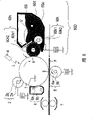
Fig. 1 is the synoptic diagram of the imaging device of 1 scheme 1 according to the embodiment of the present invention.
Fig. 2 is the synoptic diagram of the imaging device of 2 scheme 2 according to the embodiment of the present invention.
Fig. 3 be in the magnetic roller used in the embodiment 1 magnetic density and | Br|/| the curve map of B|.
Fig. 4 is the synoptic diagram according to the imaging device of the scheme 1 of comparative example 2 of the present invention.
Fig. 5 is the synoptic diagram according to the imaging device of the scheme 1 of comparative example 4 of the present invention.
Fig. 6 is the synoptic diagram according to the imaging device of the scheme 1 of comparative example 5 of the present invention.
Fig. 7 is the synoptic diagram according to the imaging device of the scheme 1 of comparative example 7 of the present invention.
Fig. 8 is the synoptic diagram according to the imaging device of the scheme 1 of comparative example 8 of the present invention.
Fig. 9 is the synoptic diagram according to the imaging device of the scheme 1 of comparative example 9 of the present invention.
Figure 10 has shown the measurement mechanism that uses the type faraday measuring method of bleeding.
Figure 11 has shown the mechanism that edge defect occurs.
Figure 12 has shown the mechanism of developing simultaneously and cleaning.
Figure 13 has shown the mechanism that the black image deflects occur.
Figure 14 is the curve map of black density assessment result.
Figure 15 is the curve map of blur prevention assessment result.
Figure 16 is the curve map of solid white image defective.
Figure 17 is the curve map of afterimage defective.
Figure 18 is total evaluation result's a curve map.
Figure 19 is the curve map of anti-afterimage assessment result.
Embodiment
An embodiment according to developing apparatus of the present invention will be described below.At first describing can be with the imaging device under a kind of scheme that developing apparatus uses.
(embodiment of the imaging device of scheme 1):
Fig. 1 is the synoptic diagram that adopts according to the image recorder (imaging device) of a kind of developing apparatus of the present invention, has shown general structure among the figure.This imaging device is the laser printer that has adopted the transfer printing type of electrophotographic processes.
(1) general structure of image recorder:
What represent with label 1 is image bearing member (object to be developed).The form of the image bearing member 1 in the present embodiment is rotatable drum (hereinafter will be referred to as photosensitive drums).Photosensitive drums is the photosensitive-member of OPC type, and its intrinsic polarity is negative pole.Its diameter is 24mm.With photosensitive drums 1 along the clockwise direction shown in the arrow with constant peripheral speed (processing speed PS; Print speed) the 85mm/s rotation drives.
What represent with label 2 is charging roller as charging device.Charging roller 2 is resilient roller of conduction, comprises the elastic layer 2b of metal-cored 2a and conduction.By applying pressure with pre-sizing, this charging roller is crimped on the photosensitive drums 1 always, between charging roller 2 and photosensitive drums 1, form charging zone n.In the present embodiment, charging roller 2 rotates with the rotation of photosensitive drums 1.
What represent with Reference numeral S1 is the power supply that charging roller 2 is applied charging biasing.In the present embodiment, the DC voltage that its potential level is higher than the starting potential of charging from charging voltage power supply S1 is applied to the contact area between charging roller 2 and the photosensitive drums 1.Or rather, will-1, the DC voltage of 300V is applied to and photosensitive drums 1 contacted charging roller 2 as the charging biasing, so as with the outside surface uniform charging of photosensitive drums 1 to potential level-700V (potential level of unexposed point).
What represent with label 4 is the laser scanner (exposure sources) with laser diode, polygon prism etc.This laser scanner is used to export the light beam L of laser, forms picture element signal with continuous electric digital picture simultaneously its intensity is modulated, so that the outside surface of the uniform charging of above-mentioned rotatable photosensitive drums 1 is scanned (exposure).Adjust Laser Power Devices, make that the current potential of this photosensitive drum surface is-150V when exposed in the whole surface of the photosensitive drums 1 of uniform charging.
By scan exposure instrument L, will be formed on the photosensitive drums 1 of rotation corresponding to the electrostatic latent image information of the image that will form.
With label 60A represent be in the imaging device of first version described later developing apparatus.By electrification by friction toner (developer) is charged to negative polarity then, and be applied to as the developing sleeve 60b of developer (toner) load bearing component (developer carrying transports parts) and the developing bias between the photosensitive drums 1 by apply power supply S2 by developing bias, this toner is used at developing location the electrostatic latent image on the photosensitive drums 1 being developed.When describing other embodiments of the present invention in the back and comparing embodiment, will describe developing apparatus 60A in detail.
What represent with label 6 is transfer roll as the contact-type transfer device, and its resistance is in intermediate range.By applying pressure with pre-sizing, transfer roll 6 is contacted with photosensitive drums 1 always, form transfer printing clamp area b.The never illustrated paper feeding of recording medium P district as the object that will write down is sent to transfer printing clamp area b, simultaneously transfer roll is applied the predetermined transfer printing biasing that applies power supply S3 from the transfer printing biasing.As a result of, when offset medium was transferred and passes through transfer printing clamp area b, the toner image on the photosensitive drums sequentially was transferred on the surface of offset medium P continuously.
What represent with label 7 is the fixation facility that has adopted heat fixer method or similar approach.Has toner image this moment on the transfer materials P in transfer printing clamp area b transfer printing on the photosensitive drums 1, this transfer materials from the surface isolation of rotatable photosensitive drums 1 and subsequently with its importing fixing device 6, wherein will be carried out photographic fixing to this transfer materials and operates and it is discharged to outside this equipment as printout or copy.
What represent with label 8 is the cleaning equipment (photosensitive drums clearer) that is used to clean photosensitive drums 1.After the image transfer printing, cleaning equipment 8 usefulness cleaning blade 8a scrapes the outside surface of photosensitive drums 1, after the image transfer printing, removes the toner on the outside surface that remains in photosensitive drums 1, and the toner of being removed is recovered among the waste toner container 8b.
After the outside surface of cleaning photosensitive drums 1, charge again by 2 pairs of these photosensitive drums of charging equipment, and use it for imaging next time.
That represent with designator 9A is handle box (process cartridge), be included in photosensitive drums 1, charging roller 2, developing apparatus 60A and the photosensitive drums clearer 8 of wherein integral installation, and be installed on the interior handle box of master component master component of imaging device separably.
(imaging device of scheme 2):
Fig. 2 is the image recorder of scheme 2, and it has adopted the developing apparatus in second embodiment of the present invention.The one-piece construction that has shown equipment among the figure.The image recorder of this programme is the laser printer of transfer printing type, and it has adopted electrophotographic processes and toner circulation process (cleaner-less system).Below the feature of those imaging devices that are different from the imaging device in the scheme 1 will only be described; To no longer describe with feature like the feature class of imaging device in first embodiment.
The fundamental difference of the imaging device in imaging device in this programme and the scheme 1 is that imaging device does not have photosensitive drums clearer 8, and the transfer printing remaining toner is circulated.In order to prevent that transfer printing remaining toner infringement property ground from influencing other processes,, the transfer printing remaining toner is carried out recycle and be recovered in the developing apparatus such as charging process.Or rather, the imaging device in the scheme 2 is carried out following structural change.
For carrying out the charging of photosensitive drums 1, adopted and the identical charging roller 2 of charging roller 2 in the scheme 1.Yet in the present embodiment, charging roller 2 is drive.Gyro frequency to charging roller 2 is adjusted, so that identical superficial velocity (processing speed) is provided between the superficial velocity of charging roller 2 and photosensitive drums 1.Charging roller 2 is independent of photosensitive drums 1 and drives, and has guaranteed that charging roller 2 and photosensitive drums 1 and charging roller contact component 20 keep in touch, toner is charged to negative polarity (conventional polarity).Furtherly, to have the Another reason of contact component 20 be contaminated in order to prevent charging roller 2 to charging roller 2.Contact component 20 has been arranged, even charging roller 2 is polluted by the toner of its polarity with the polarity opposite (just) of the charging biasing of charging roller 2, the polarity of the toner of this contaminative also can become negative pole by positive pole, make its ejection from charging roller 2 promptly, with with by the sub-image on the developing apparatus development photosensitive drums 1 identical time and position, it is recovered in the developing apparatus.Contact component 20 is that the Kapton of 100 μ m constitutes by thickness, and contacts with charging roller 2, so that keep the line pressure of 10 (N/m) between contact component 20 and charging roller 2.Adopt the reason of polyimide to be that polyimide has the characteristic that toner is charged to negative polarity by electrification by friction.
What represent with designator 9B is handle box, and wherein photosensitive drums 1, charging roller 2, charging roller contact component 20 and developing apparatus 60A in integral installation, and it is built in the master component master component that can be removably installed in imaging device.
(embodiment of developing apparatus and comparative example):
(embodiment 1 of developing apparatus):
Present embodiment has been used contact-type, spring-backed quill and position adjustments (sheet metal) between polarity.
To describe below present embodiment developing apparatus 60A (Fig. 1, Fig. 2).
What represent with label 60b is developing sleeve as developer bearing part (developer carrying transports parts), and wherein the magnetic roller 60a as magnetic field generation device fixes, non-rotatably installs.Developing sleeve 60b comprises: aluminium matter right cylinder 60b1 (basic components), the layer 60b2 (elastomeric element) that the non magnetic conductive materials on aluminium matter right cylinder 60b 1 outside surface constitutes.With predetermined pressure developing sleeve 60b is pressed on the photosensitive drums 1.Pressure between photosensitive drums 1 and the developing sleeve 60b is adjusted into 200N/m (tensile pressures).Here, tensile pressures is the force value corresponding to line pressure, is to stretch to be clipped in two thickness and to be respectively power on thick needed each meter of SUS (stainless steel) thin plate of 30 μ m between the SUS thin plate of 30 μ m.
The manufacture process of the developing sleeve 60b of present embodiment is, mediates the material that is used for non magnetic conductive elastic layer 60b2, extrudes the material after the kneading, and the material of extruding is gone up cambium layer 60b2 attached to aluminium matter sleeve pipe 60b1, and with the thickness of this layer polishing to 500 μ m.The microhardness of developing sleeve 60b is 95 °, and surfaceness Rz is 3.8 μ m, and surface roughness Ra is 0.6 μ m.
In the present embodiment, with having measured skin hardness from the micro Vickers hardness meter Asker MD-1F360A that Japanese Kobunshi Kabushiki Kaisha company obtains.Measuring length is that 2.5mm, vertical direction are amplified 2000 times, horizontal direction to amplify 100 times, cutoff level be that 0.8mm, filtrator are set to 2CR, measurement of the level is set under the data conditions of the place ahead, the surfcorderSE3400 that use can obtain from Japanese KOSAKA KENKYUSHO Kabushiki Kaisha company, and use contact detection unit PU-DJ2S, measured surfaceness.
The DIELECTRIC CONSTANT s of elastic layer 60b2 is 6.5.Apply 1Vpp voltage, frequency is 1kHz, gets under the condition of 10 measurement points, by counting (HP4284A) from the accurate LCR that Hewlett-Packard company obtains, and be used to measure the electrode (HP 16451B) of insulating element, measured specific inductive capacity.
Magnetic roller 60a is a fixing magnet, is used as the magnetic field generation device of the pre-position generation magnetic force on the developing sleeve 60b.As shown in Figure 3, all there are density peaks, transport portion (the conveying utmost point) N α, supply with part (the supply utmost point) S β and collect part (collector) N β at each district S α (the development utmost point) that develops.In the present embodiment, used and to have measured magnetic density from the 9900 serial gaussmeters that have probe A-99-153 that Bell company obtains.Gaussmeter has the shaft-like axial probe that is connected to this gaussmeter master component.60b is fixed on horizontal level with developing sleeve, and magnetic roller 60a is rotatable.With respect to developing sleeve 60b, probe keeps horizontality vertically to install with a little gap, and being centered close in the same surface level of the center of developing sleeve 60b and probe.They are placed the said fixing position, and measure magnetic density.Magnetic roller 60a and developing sleeve 60b are concentric basically, therefore think gap between magnetic roller 60a and the developing sleeve 60b be with magnetic roller 60a on the irrelevant constant of peripheral position.From this viewpoint, by measure on the developing sleeve 60b surface and should the surface on the magnetic density of normal direction, rotate magnetic roller 60a simultaneously, can measure all positions of developing sleeve 60b circumferencial direction.According to the magnetic density data that obtain in peripheral direction, determined the intensity peak of each position, this value is a normal component Br, the i.e. normal component of sleeve surface.Then, with the tangential direction half-twist of normal direction probe towards developing sleeve 60b, and rotation magnetic roller 60a, so that in the magnetic density of the relevant position on developing sleeve surface measurement as the tangential direction of tangential component B Θ.
According to the Br value and the B Θ value of respective angles position, calculate magnetic density in each corresponding angular position on developing sleeve surface | B|=|Br2+B Θ 2|1/2.
Then, determine normal component | Br| and magnetic density | the ratio of B| | Br|/| B|.
Described result and Br and B Θ are shown in Fig. 3 (b).With respect to the angle of horizontal ordinate, initial point is corresponding to supplying with the part S β utmost point, and the forward edge is with respect to the downstream (S β-N α-S α-N β-S β) of the sense of rotation of sleeve pipe.Dexter ordinate is represented the intensity of magnetic density, and the N utmost point is anodal, and the S utmost point is a negative pole, the ordinate representative of left-hand side | Br|/| B|.
Single component magnetic toner t1 (developer) is by mixing and mediating adhesive resin, magnetic particle and charging and regulate material, and milled mixtures, and the material after will grinding is then classified and generated.The extra liquefied material that adds.Developer comprises the magnetic particle and the adhesive resin of same weight, so that the magnetic particle that can carry by enough strong magnetic force to be provided.The average particle size of toner (D4) is 8 μ m.
Under the effect of the magnetic force of left magnetic roller 60a, on developing sleeve 60b, transport in the process of toner t1, the adjustment sheet 60c (developer level adjusting parts) of the amount by being used to regulate the developer on the developing sleeve regulates toner and carries out bed thickness and regulate, and by electrification by friction this toner is charged.What represent with label 60d is to be used for making toner to circulate and carry the stirring parts of toner in the magnetic force scope of sleeve surface subsequently at developer container 60e.
In the developing apparatus 60A of present embodiment, for toner charge amount that expectation is provided with cover the amount of being coated with, the adjustment sheet 60c that regulates parts as developer level is that the phosphor bronze of 120 μ m constitutes by thickness, with respect to the contact position (adjusting position) of developing sleeve 60b be Θ=38 shown in Figure 3 ° (| Br|/| B|=0.03), tensile pressures is 55N/m, and the drift of adjustment sheet is 2.5mm.The length of the free part on the adjustment sheet is exactly from the length with respect to the contact portion of the adjustment sheet 60c of developing sleeve 60b.Here, in mode of the present invention, be called as " intermediate regulations " (positions in the middle of the two poles of the earth) and be meant, the contact position of adjustment sheet 60c to developing sleeve 60b is set in the pole regions that is mainly horizontal magnetic field (| Br|/| B|<=0.5).The developing apparatus of present embodiment does not have and is used to supply with the reagent delivery component of toner to developing sleeve.What therefore, developing sleeve at first contacted after the contact photosensitive drums is exactly adjustment sheet.
By the rotation of developing sleeve 60b, be transported to the district of developing (the district's part of developing) a with being added in toner t1 on the developing sleeve 60b, surperficial relative in develop district a developing sleeve 60b and photosensitive drums 1.Developing sleeve 60a is applied the developing bias voltage (only apply-DC voltage of 450V and do not have the alternating voltage component) that applies voltage source S2 from developing bias.
Developing sleeve 60b and adjustment sheet 60c are electrically connected, so that its current potential equates.1.2 times peripheral speed drive developing sleeve 60b with the peripheral speed of photosensitive drums 1.By discharged-area development, the electrostatic latent image on the photosensitive drums 1 is developed with developer t1.Here, the peripheral speed of developing sleeve 60b is 1.2 times with respect to the peripheral speed of photosensitive drums 1, but this is not inevitable, and might be photosensitive drums 1 peripheral speed 1.0-2.0 doubly, this is an advantage of present embodiment.
(comparative example 1 of developing apparatus) contact-type spring-backed quill, electrode position is regulated:
The developing apparatus 60A of developing apparatus of this comparative example and embodiment 1 is similar, but adjustment sheet 60c is different with the contact conditions of spring-backed quill (developing sleeve 60b).
As shown in Figure 3, in this comparative example, the contact position of adjustment sheet 60c be Θ=84 ° (| Br|/| B|=0.99), tensile pressures is 80N/m, and the drift of adjustment sheet is 1.5mm.
Here, so-called " electrode position adjusting " be meant, in the pole regions that is mainly vertical magnetic field (| Br|/| B|>=0.9), the contact position of adjustment sheet 60c and developing sleeve 60b is set.
(comparative example 2 of developing apparatus) magnetic non-contact type elasticity toning system, intermediate regulations:
The developing apparatus 60B of this comparative example will be described below.Fig. 4 is to use the synoptic diagram of imaging device of scheme 1 of the developing apparatus of this comparative example.Toner used herein is toner t1 described later.
What represent with label 60f is the developing sleeve (developer carrying member) that comprises the magnetic roller 60a identical with magnetic roller in the embodiment 1.Developing sleeve 60f has through sandblasting to handle the aluminium matter right cylinder on the roughness surface of expecting with acquisition, and it is installed with respect to photosensitive drums 1, leaves the gap α of 300 μ m between the two.The microhardness of developing sleeve 60f is 100 °, and surfaceness Rz is 11.5 μ m, and Ra is 1.5 μ m.The toner t1 that is filled in the developing apparatus 60B is transported by developing sleeve 60f, and is subjected to the effect of the magnetic force of magnetic roller 60a simultaneously.And, in this process, toner t1 is carried out the adjusting of bed thickness, and is that the adjustment sheet 60g that is made of polyurethane of 1.5mm regulates by thickness.What represent with label 60d is to be used for making toner to circulate and carry the stirring parts of toner in the magnetic force scope of sleeve surface subsequently at developer container 60e.
In the developing apparatus 60B of this comparative example, for toner charge amount that expectation is provided with cover the amount of being coated with, adjustment sheet 60g is Θ=38 shown in Fig. 3 (b) ° with respect to the contact position of developing sleeve 60f, wherein | Br|/| B|=0.03, tensile pressures is 30N/m, and the drift of adjustment sheet is 1.2mm.
By the rotation of developing sleeve 60f, be transported to the district of developing (the district's part of developing) with being added in toner t1 on the developing sleeve 60f, surperficial relative in develop district developing sleeve 60f and photosensitive drums 1.Developing sleeve 60f applied comprise-developing bias voltage of the AC compounent (square wave) of DC voltage component, 1.8kVpp and the 1.6kHz of 450V.1.2 times peripheral speed drive developing sleeve 60f with the peripheral speed of photosensitive drums 1.By this way, with developer t4 to the electrostatic latent image on the photosensitive drums 1 develop (discharged-area development).This developer is exactly toner t1 used in the embodiment 1.
(comparative example 3 of developing apparatus) magnetic non-contact type is developed, and electrode position is regulated:
This comparative example is similar with the developing apparatus 60B of comparative example 2, but adjustment sheet 60g is to the contact conditions difference of spring-backed quill 60f.
As shown in Figure 3, in this comparative example, the contact position of adjustment sheet 60g be Θ=84 ° (| Br|/| B|=0.99), tensile pressures is 80N/m, and the drift of adjustment sheet is 1.5mm.
(comparative example 4 of developing apparatus) rigid element sleeve pipe, the contact-type toning system, intermediate regulations:
The developing apparatus 60B of developing apparatus of this comparative example and comparative example 2 is similar, but exists different in the following areas.
The developing sleeve 60f that does not have elastic layer of aluminium matter cylindrical shape contacts with photosensitive drums 1 with predetermined pressure.Tensile pressures between photosensitive drums 1 and the developing sleeve 60g is 50N/m.The developing bias that is applied has only-DC voltage of 450V.
(comparative example 5 of developing apparatus) non-contact type spring-backed quill, intermediate regulations:
Fig. 6 is to use the synoptic diagram of imaging device of scheme 1 of the developing apparatus of this comparative example.
The difference of the developing apparatus 60A of developing apparatus of this comparative example and embodiment 1 is as follows:
(comparative example 6 of developing apparatus) non-contact type spring-backed quill, electrode position is regulated:
Fig. 6 is to use the synoptic diagram of imaging device of scheme 1 of the developing apparatus of this comparative example.
The imaging device of developing apparatus of this comparative example and embodiment 1 is similar, but exists different in the following areas.
(comparative example 7 of developing apparatus) rotary-type multi-pole magnetic roller:
The developing apparatus 60C of this comparative example will be described below.Fig. 7 is to use the synoptic diagram of imaging device of the scheme 1 of comparative example 7.
What represent with label 60r is the developing sleeve (developer carrying member) that comprises magnetic roller 60q.Developing sleeve 60r comprises: aluminium matter right cylinder 60r1, the layer 60r2 that the non magnetic conductive materials on the aluminium matter right cylinder 60r1 outside surface constitutes.With predetermined pressure developing sleeve 60r is crimped on the photosensitive drums 1.Tensile pressures is 200N/m.
The manufacture process of developing sleeve 60r is, mediates the nonmagnetic substance that is used for conductive elastic layer 60r2, extrudes the material after the kneading, attached on the aluminium matter sleeve pipe 60r1, and is 500 μ m with surface finish to the thickness of layer 60r2 with the material extruded.The microhardness of developing sleeve 60r is 94 °, and surface roughness Ra is 1.2 μ m.
Under the effect of the magnetic force of left magnetic roller 60q, on developing sleeve 60q, transport toner t1, in this process, regulate the bed thickness of toner t1, and this toner t1 is charged by electrification by friction by adjustment sheet 60c.What represent with label 60d is to be used for making toner to circulate and carry the stirring parts of toner in the magnetic force scope of sleeve surface subsequently at developer container 60e.
It partly is that 1.2mm and tensile pressures are the adjustment sheet 60c of 30N/m that the developing apparatus 60C of this comparative example has adopted drift, so that the toner charge amount of expectation is provided and covers the amount of being coated with.
By the rotation of developing sleeve 60r, be transported to the district of developing (the district's part of developing) with being added in toner t1 on the developing sleeve 60r, surperficial relative in develop district developing sleeve 60r and photosensitive drums 1.To developing sleeve 60r apply apply power supply S2 from developing bias developing bias voltage promptly-DC voltage of 450V.1.2 times peripheral speed drive developing sleeve 60r with the peripheral speed of photosensitive drums 1.By this way, by discharged-area development, the electrostatic latent image on the photosensitive drums 1 is developed with toner t1.
Here identical in used toner t1 and the embodiment 1.
Japan patent applicant announce Hei4-15949 discloses a kind of developing apparatus of similar of and this comparative example.
(comparative example 8 of developing apparatus) non magnetic contact-type toning system:
The developing apparatus 60D of this comparative example will be described below.Fig. 8 is to use the synoptic diagram of imaging device of scheme 1 of the developing apparatus of comparative example 8.
What represent with label 60h is the developer roll that comprises core metal 60h1 and conductive elastic layer 60h2 formed thereon.Predetermined pressure with 20N/m contacts developer roll 60h with photosensitive drums 1.The axle that resilient roller 60k is fixed on resilient roller 60k and developer roll 60h is at a distance of the preset distance part, and the tensile pressures between the two is 40N/m.Developer roll 60h is with 1.4 times peripheral speed rotation of the peripheral speed of photosensitive drums 1, and resilient roller 60k rotates along the direction opposite with this developer roll with identical peripheral speed.Under 500g load, the rubber hardness of developer roll 60h is ASDER C50 °, and microhardness is 42 °.
By drive disk assembly 60d toner t2 is supplied to resilient roller 60k.By rotation, resilient roller 60k supplies to developer roll 60h with toner t2.By electrification by friction the toner that is added on the developer roll 60h is charged, and it is adjusted in certain bed thickness by adjustment sheet 60i.The toner that is transported to developer roll 60h is used at the district a that develops the electrostatic latent image on the photosensitive drums 1 being developed.Toner that does not run out of in the development and the toner that remains on the developer roll 60h are wiped down by resilient roller 60k, and circulate in container 60e, and then are added on the surface of developer roll 60h.
The developing bias voltage that puts on the core metal 60h1 of above-mentioned developer roll includes only DC component (DC voltage of 450V).Resilient roller 60k is also applied identical developing bias with adjustment sheet 60c.
Here used toner t2 is a single component magnetic toner, by mixing and mediating adhesive resin, colouring material, magnetic particle and charge control material and it is ground and classification generates.This toner also comprises and is used for additional materials that charged particle m is liquefied and charges.The average particle size of this toner (D4) is 8 μ m.
(comparative example 9 of developing apparatus) non-contact type conveying roller:
The developing apparatus 60E of this comparative example will be described below.Fig. 9 is to use the synoptic diagram of imaging device of the scheme 1 of comparative example 9.
What represent with label 60h is the developer roll that comprises core metal 60h1 and conductive elastic layer 60h2 formed thereon.With label 60j represent be the discharge sheet comprise the conducting strip 60j2 of lining on elastomeric element 60j1.With 2 predetermined pressures developer roll 60h is contacted with photosensitive drums 1 corresponding to the 20N/m tensile pressures.To discharge sheet 60j to developer roll 60h pushing with predetermined pressure, make that tensile pressures is 55N/m.Developer roll 60h is with 1.4 times peripheral speed rotation of the peripheral speed of photosensitive drums 1.Toner carrying roller 60n does not contact with developer roll 60h, and with the peripheral speed rotation identical with this developer roll.Under 500g load, the rubber hardness of developer roll 60h is 50 ° of ASDER C, and microhardness is 42 °.
By stirring parts 60d toner t2 is supplied to resilient roller 60k.The conveying roller 60n that installs non-contiguously with developer roll 60h supplies to developer roll 60h by rotation with toner t2.By electrification by friction the toner that is added on the developer roll 60h is charged, and it is adjusted in certain bed thickness by adjustment sheet 60i.The toner that is transported to developer roll 60h is used at the district a that develops the electrostatic latent image on the photosensitive drums being developed.Toner that does not run out of in the development and the toner that remains on the developer roll 60h discharge by discharge sheet 60j, and circulate in container 60e, and then are added on the surface of developer roll 60h.
Put on developing bias on the above-mentioned core metal 60h1 and be-DC voltage of 450V.Conveying roller 60n and adjustment sheet 60i are also applied identical developing bias current potential.
Here identical in used toner t2 and the comparative example 8.
Jap.P. No.3225759 disclose a kind of developing apparatus of similar of and this comparative example.
(measure the concrete quantity of electric charge of toner and cover the amount of being coated with)
The concrete quantity of electric charge of toner and cover the amount of being coated with and measure as follows.Cover the quantity of electric charge that is coated in the developer on developer roll or the developing sleeve by the so-called type faraday measuring method measurement of bleeding.Figure 10 has shown the measurement mechanism that uses the type faraday measuring method of bleeding, and wherein extraction opening 11 is extracted developer out toner is collected on the filtrator 12 that has in the inner cylinder near developing sleeve or developer roll.At this moment, inner cylinder is an electrostatic screening to the outside, by measuring the quantity of electric charge Q (C) of the developer of accumulation herein from the electrometer 6517A that KEITHLEY company obtains.Calculate the weight M (g) of the toner of being extracted out according to the increase of filtrator weight, and measure the area S (m of the toner correspondence that is extracted
2).Then, calculate the concrete quantity of electric charge Q/M (μ c/g) of the toner on the sleeve pipe and cover the amount of being coated with M/S (g/m
2).For above-mentioned measurement, during pure white printing is operated, stop operation, and developer roll or developing sleeve are measured the master component of pen recorder.
(present embodiment is with respect to the advantage of prior art)
(to the appraisal procedure of embodiment 1 and comparative example 1-9)
Below with the image evaluation of the difference between descriptive study embodiments of the present invention 1 and the comparative example 1-9.
Image evaluation in the scheme 1 (having used Fig. 1 of photosensitive drums clearer 8):
A) to the assessment of blur prevention:
Here, " bluring " means that toner sticks to the phenomenon that white (unexposed) zone is the toner zone that should not adhere to originally slightly, and this white (blank) part that causes result images is as contaminated.
Measure fuzzy quantity by this way.Use green filters, by measuring the optical reflection coefficient of white portion from the optical reflection coefficient measuring instrument TC-6DS that Denshoku company in Tokyo obtains, the difference of the reflection coefficient that obtains during with above-mentioned measurement result and measurement cardboard is as above-mentioned fuzzy reflection coefficient.When determining fuzzy quantity, tackle on the recording chart 10 different points at least and measure, and with the average of measurement result as fuzzy quantity.
N: fuzzy quantity is greater than 2%
F: fuzzy quantity is 1-2%
G: fuzzy quantity is 0.5-1%
E: fuzzy quantity is less than 0.5%
Behind 3000 printer papers, 100 initial paper are carried out the blur prevention assessment.In printing test, the print image ratio is 5% horizontal line figure continuously repeatedly.If the image deflects beyond the following defective, then this defect part is got rid of outside only to the fuzzy measurement of estimating.
B-1) amount of remaining toner fuzzy behaviour assessment more after a little while:
Along with the repetition of printing test, the amount of the toner in the developing apparatus has reduced, so the image density of horizontal line reduces, and under extreme case, horizontal line partly disappears.Blur prevention performance when reducing for the amount of remaining toner, assessment is independently to carry out.In printing test, when above-mentioned defective appears in horizontal line figure, carry out the blur prevention assessment, then, from pen recorder, unload developing apparatus, and this developing apparatus of hand shaken is to be transported to toner developing sleeve and developer roll.Then, developing apparatus is installed back in this equipment, and carry out the blur prevention assessment.In such image evaluation, the blur prevention assessment all is similarly, and the fuzzy blur prevention that is used for that situation is the poorest is assessed.
The fuzzy reason that produces when B-2) amount of remaining toner reduces:
By spongy conveying roller is contacted with developer roll, nonmagnetic toner is transported on the developer roll, so that reciprocal peripheral motion is provided.Therefore, by the sliding contact between developer roll and the conveying roller, the degeneration of toner is remarkable, and charge characteristic descends as a result.Therefore, fuzzy quantity increases along with the increase of the printing amount (particularly underload printing) that produces.
And under a kind of like this toner supply mechanism, the replacement of toner is rare around developer roll, thereby produces toner round-robin zone not therein.On the other hand, the round-robin toner degenerates to a certain degree.Under the situation that lacks toner, when shaking handle box, toner mixing mutually in developer container that those do not degenerate to the toner of above-mentioned degree and have degenerated to above-mentioned degree, the toner particle that promptly has opposed polarity mixes mutually, causes fuzzy quantity significantly to increase.
This is because when such mixing occurring and toner charged, the toner of Tui Huaing does not have charge characteristic preferably, and the toner after degenerating almost can not be recharged, or has and the opposite polarity polarity of routine.Those toners that therefore are not recharged or are charged to opposite polarity have caused the increase of fuzzy quantity.
Toner with opposite polarity has caused fuzzy, because the direction of the power that the direction of the power that these toners are subjected to and the toner of routine are subjected to is opposite, therefore, these toners with opposite polarity are transferred to nonprinting region.
Under the situation of using magnetic color tuner, carry toner by magnetic force, so toner can not degenerated significantly.Even just shook handle box before toner lacks, the toner particle with opposite polarity can not mix yet, thereby has prevented that toner lacks fuzzy before increase.
C-1) afterimage:
According to overlapping supply and the removing performance of assessing developer of developing.Consider the peripheral speed and the processing speed of developer roll and developing sleeve,, check the afterimage that on interval, occurs corresponding to the swing circle of developer roll or developing sleeve for this assessment.Distinguish by this way and afterimage whether occurred.Front end at page is printed 5mm
2And 25mm
2The black blocking picture, just formed the medium tone image then at once.If the density variation between medium tone image section and the part of black before can be discovered by naked eyes, then can judge to have produced afterimage.Used scanner is the laser scanner of 600dpi in the test.In above-mentioned test, with the image replacement medium tone image that is included in the delegation of extending on the main direction of scanning and unprinted four lines subsequently.This image has just replaced the medium tone image fully like this.
The process of image evaluation is as follows:
N: the afterimage in the blocking picture is all distinguished out.
F: have only the afterimage in the secondary blocking picture to be distinguished out.
G: the afterimage in the blocking picture is not all distinguished out.
100 initial paper are assessed.
C-2) reason of afterimage generation:
The developing apparatus of present embodiment comprises photosensitive drums and pressure developing sleeve thereon, does not comprise and removing and donor rollers.In such developing apparatus, with new toner supply to the spring-backed quill part that in last time rotation, consumes toner, and with this toner supply to regulating part.When printing the black image, with the amount of being coated with of covering that consumes more than 90%.Therefore, the toner that is deposited on the part that consumes toner has comprised the toner of the new supply of big number percent.On the other hand, the toner that does not consume in last time rotation on the part of toner returns the supply part.Therefore, the toner that deposits after this comprises the toner of the new supply of less number percent.By this way, be transported to the toner of regulating part and comprised the rate variance of new toner to old toner, this depends on the difference of the consumption in the former rotation.Between upper strata toner and lower floor's toner, do not exchange, be that toner does not have fully to go up when wipe on the surface of sleeve pipe, uniformly the medium tone image may comprise with rotation before sleeve pipe in the corresponding afterimage of delayed action of consumption of toner.
D-1) uniformity coefficient of fine rule:
For this purpose and the image evaluation that carries out based on a dotted line on vertical and horizontal continuity and carry out.Used scanner is the laser scanner of 600dpi in the test.Handle the direction carry out and the dotted line that extends and be parallel to the main direction of scanning of laser scanning system and the dotted line that extends is all assessed to being parallel to.In each comparative example, all print the fine rule figure of so long 2cm, and select 100 lines at random.For in 100 points each, by observation by light microscope the area of single line being arranged therebetween is 200 μ m
2The zone.For every line, with the density half-peak value width of this line as the width of this line and determine.Calculate the standard deviation of the width that each direction reaches the standard grade.According to the standard deviation h on the laser scanning direction of line standard deviations v on the processing direction that calculates and calculating, obtain the standard deviation rate σ v/ σ h of line.Utilize the value that obtains thus, carry out following assessment:
N: the standard deviation rate σ v/ σ h of line is less than 0.7 or greater than 1.43.
F: the standard deviation rate σ v/ σ h of line is more than or equal to 0.7, less than 0.8, or more than or equal to 1.25, smaller or equal to 1.43.
G: the standard deviation rate σ v/ σ h of line is more than or equal to 0.8, less than 1.25.
100 initial paper are assessed.
D-2) reason of fine rule uniformity coefficient decline:
In the magnetic noncontact is developed, there is the mutually different problem of vertical uniformity coefficient with fine rule level.During carrying out in development operation, the direction the when working direction that is parallel to photosensitive drum surface when magnetic linkage moves, the uniformity coefficient of fine rule is better, but the fine rule on the vertical direction almost breaks.
E-1) image border defective:
For the image border defective, the boundary between high density part and low-density part, density variation is less.
For carrying out image evaluation, in the medium tone image, print 25mm
2The black image.In above-mentioned assessment, be used in and comprise a point and unprinted four points subsequently on the main direction of scanning and on sub scanning direction, comprise a point and the image of unprinted four points subsequently replaces the medium tone image.This image has just replaced the medium tone image fully like this.Marginal portion between half tint and black part, with medium tone one side of microscopic examination marginal portion, and the number of the toner particle in the point of calculating toner conglomerate.And, in distance marginal portion part enough far away, calculate the toner particle number in the point.When the toner particle in calculating a point is counted, randomly draw 15 points, and with the average of toner particle number as the toner particle number in the point.
N: the toner particle number of edge is smaller or equal to 60% of the toner particle number of distance marginal portion part enough far away.
G: the toner particle number of edge is greater than 60% of the toner particle number of distance marginal portion part enough far away.
100 initial paper are assessed.
E-2) reason of image border defective generation:
Below with reference to Figure 12 the reason that the image border defective produces is described.When the P-to-P voltage Vpp of alternating voltage was big, the exchange of toner particle took place in the district of developing.As shown in figure 11, if there is the bigger zone of density variation this moment, then toner particle is exchanging near boundary, and these toner particles attracted to has highdensity print area, and therefore, the density of low-density part is lower than expectation value at boundary member.
F-1) solid white image defective:
Carry out image evaluation according to the image deflects that on the interval that equals developing sleeve or developer roll cycle period, occur.Consider the peripheral velocity ratio between processing speed and photosensitive drums and the developing sleeve, accurate Calculation is developed the cycle.Then, extract and check the image deflects that appear on the cycle period out.The wide approximately 2-3mm of image deflects, long 3-10mm, indicative of local optical density is about 0.3-1, and these image deflects are checked individually.Can on defective existence or non-existent basis, clearly assess.Evaluation process is as follows:
N: image deflects are arranged.
F: do not have image deflects.
For this assessment, print 10 solid white image continuously.
F-2) reason of solid white image defective generation:
Solid white image does not consume toner, and the amount that therefore turns back to the toner of supplying with part is bigger.In this case, if the not fully exchange of old toner particle and new toner particle, then through after the adjustment sheet, toner covers the concrete CHARGE DISTRIBUTION of coating and/or covers the thickness of coating inhomogeneous easily.If concrete CHARGE DISTRIBUTION is inhomogeneous, the then local toner that exists with the concrete electric charge that is higher than conventional electric weight.Such toner has the stronger power that deposits to sleeve surface, thereby is difficult to be replaced.Therefore, by continuous printing solid white image, this phenomenon can occur significantly.When with new toner supply in toner the time, can descend with respect to the toner charge characteristic of sleeve surface, thereby can not correctly charge with higher concrete electric charge.As a result of, a certain amount of toner with electric weight of low concrete electric charge or opposite polarity appears in the surface of covering coating at toner, therefore when adopting the sleeve pipe that is pushed to or touches photosensitive drum surface to carry out development operation, toner is deposited on non-printing (white) part of photosensitive drums, thereby the solid white image defective occurs.When situation in uneven thickness took place, some part can have the toner bigger than its peripheral part and cover the amount of being coated with.Cover the bigger part of the amount of being coated with at toner, it is more to turn back to the toner of supplying with part, thereby makes the toner after the degeneration participate in replacement or exchange process.Covering the bigger part of the amount of being coated with, between sleeve pipe and photosensitive drums, toner is subjected to higher local pressure, therefore in the higher part of pressure, toner moves to such an extent that do not move more slowly or fully, so the toner at this place does not consume and arrive the supply part, is supplying with part, be difficult to replace between this toner and the new toner of supplying with, reason is to have higher physical deposition power between toner and the spring-backed quill surface.Therefore, when when supplying with part and supply with new toner, the toner charge characteristic is enough with respect to spring-backed quill, thereby has produced the toner with low concrete electric charge or opposite polarity.This is the reason that the solid white image defective produces.
Specifically, in imaging device according to the cleaner-less system of scheme 2, when the solid white image defective occurring, transfer roll is contaminated, even to carrying out charging degree owing to the pollution of charging roller, and might black figure occur on whole surface, transfer materials might twist on the fixing device, causes equipment failure.For this reason, in the system of cleaner-less, very important when preventing the solid white image defective.
G-1) medium tone image deflects 1 h):
For for this purpose and the image evaluation that carries out, print the medium tone image, assessment is carried out based on the quantity of image deflects.Used scanner is the laser scanner of 600dpi in the test.In this test, with the medium tone image with the image replacement medium tone image that is included in the delegation of extending on the main direction of scanning and unprinted four lines subsequently.This image has just replaced the medium tone image fully like this.
In this comparative example, the uniformity coefficient of medium tone image pays particular attention to, and diameter is that 0.3mm or bigger white point or stain all will be taken into account.
N: in the medium tone image diameter more than or equal to the number of the white point of 0.3mm or stain greater than 5.
F: diameter is 1-5 more than or equal to the white point of 0.3mm or the number of stain in the medium tone image.
G: diameter is 0 more than or equal to the white point of 0.3mm or the number of stain in the medium tone image.
Text to 2000 paper printing is assessed.
G-2) reason of medium tone image deflects 1 generation:
When the toner conglomerate or when having imported outside material, cover coating and just be subjected to interference, and the agglomerating toner that produces corresponding to the medium tone image of the size of defective or the size of exterior materials.
H) black image density assessment:
The imaging device of employing scheme 1 is printed the black image on the whole surface of paper, and by measuring the optics reflection density from the densitometer RD-1255 that Macbeth company obtains.Evaluation process is as follows:
N: density is less than 1.2.
F: density is 1.2-1.4.
G: density is more than or equal to 1.4.
The density assessment is carried out in the 100th time initial printing and the 3000th printing.In printing test, repeatedly continuous print image ratio is 5% horizontal line figure.Evaluation Environment is 15.0 ℃ and 10%Rh.
I-1) image evaluation of toner GTG:
Imaging device with respect to embodiment 1 is assessed the toner GTG.Used scanner is the laser scanner of 600dpi in the test.Printing wide is the longitudinal band of 1cm, does not have at interval between the adjacent ribbons.One end is pure white longitudinal band, and the other end is the black longitudinal band.All the other 10 bands are the medium tone images that are made of the point that has the different area ratio under 10 GTGs.Assessment is undertaken by with reference to following data 12 longitudinal bands being carried out visual observation:
N: recognizable longitudinal band number is smaller or equal to 7.
F: recognizable longitudinal band number is 8-10.
G: recognizable longitudinal band number is 11-12.
After taking second place, initial print 100 carries out the assessment of toner GTG.In printing test, repeatedly continuous print image ratio is 5% horizontal line figure.
I-1) reason of toner GTG regenerability degeneration:
If the uniformity coefficient of the concrete electric charge of toner descends, then be added on the corresponding toner particle on the developing sleeve and also become inhomogeneous with the electric power (electrical force) on the identical electrostatic latent image current potential that toner is sent to photosensitive drum surface.In the contact-type toning system, as a result of, the less difference of the electrostatic latent image current potential of can not regenerating reliably.
On the other hand, in the non-contact type toning system, jump on the photosensitive drums from developing sleeve, need apply electric field intensity above intended level in order to make toner.In other words, thresholding is less in the contact-type toning system, and thresholding is bigger in the non-contact type toning system, therefore, in the non-contact type toning system, can not successfully transmit toner as in the contact-type toning system.In addition, owing to there is an above-mentioned thresholding, the electric power that is received by the corresponding toner particle on the developing sleeve is with respect to the ratio of the electrostatic latent image current potential with less difference on the photosensitive drums ratio less than the electrostatic latent image current potential.Yet in this state, the alternating voltage that will be used to carry out in the developing bias of toner particle exchange is included, and helps to realize that high gray develops, i.e. toner GTG regeneration is reliable to electrostatic latent image.Yet, be that thresholding is exactly sharp-pointed, thereby makes that jumping out of toner is binary type, so the toner GTG might be a binary type uniformly if the electric weight of toner distributes.
Below with the various image evaluations in the imaging device of description scheme 2.
A-1) toner in the cleaner-less system is collected characteristic:
For this assessment, print the black image of 30-50mm at the front end in print image zone, then image recording structure is operated the assessment pattern that has solid white image with printing, and during printing, stop operation image recording structure.The time that stops is exactly that the core of the black image of front end arrive to develop in the district.Before developing and each some place's measurement afterwards be deposited on the reflection coefficient of the toner of photosensitive drum surface.Can assess the toner collection efficiency based on the ratio between the reflection coefficient.In fact,, then it is sticked on the plain pape, and measure the clean reflection coefficient of toner in the mode identical with the measurement mode paste property with the transfer printing on oolemma of the toner on the photosensitive drums.
N: collection rate is less than 30%.
F: collection rate is less than 50%.
G: collection rate is more than or equal to 50%.
100 initial paper are assessed.
A-2) toner in the cleaner-less system is collected the reason of performance degradation:
The remarkable different of the imaging device of the imaging device of scheme 2 and scheme 1 are to have removed the photosensitive drums clearer, and the toner of transfer printing is not collected in the developing apparatus and used.In the present embodiment, with predetermined pressure developer carrying member 440 is contacted with photosensitive drums 1, and these parts are applied developing bias voltage.Simultaneously, adopted the toner that is used to form in the electrostatic latent image of photosensitive drum surface to carry out development operation (visual), and collected by the toner that developing apparatus will remain in unexposed portion (white background part).As shown in figure 12, use the potential difference (PD) between developing bias and the printing portion (the current potential V1 of the bright part under the black image situation) that toner is sent to photosensitive drums to carry out discharged-area development from developer carrying member, and the potential difference (PD) between the current potential Vd (black appliances position) of use developing bias and non-printing portion, toner is sent back developer carrying member from photosensitive drums.
In addition, by the crimping between developer carrying member and the photosensitive drums, reduced the distance between the two, thereby increased field intensity, to improve the performance of developing simultaneously and collecting.
In addition, above-mentioned crimping structure also can be guaranteed to develop and collect operation by electric field, and this is because the useful area of development retained part has increased, and this has promoted to make the electric charge of the toner that returns for negative, in addition, the useful area increase of development retained part makes the toner that returns become loose.
On the other hand, when with developer carrying member when relative with photosensitive drums non-contiguously, the distance between the two is bigger, therefore, the magnetic force that is used to collect relative with electric power a little less than.This has reduced the efficient of collecting.
Under with photosensitive drums and the mutual crimping of developer carrying member situation together, the pulling force that produces by the object contact, Van der Waals (van der Waals) power, between photosensitive drums and the toner, between toner and the developer carrying member, identical between toner and the toner.Therefore, power is not the reason that causes collecting performance degradation.Yet, under developer carrying member is not in contact with situation on the photosensitive drums, have only photosensitive drums and the toner that returns between have Van der Waals for, this has hindered the removal of toner from photosensitive drums, and causes collecting performance degradation.
B-1) medium tone image deflects 2 (imaging device of scheme 2):
Similar with the imaging device of scheme 1, the imaging device of scheme 2 is prevented the assessment of medium tone image deflects.
B-2) reason of medium tone image deflects 2 generations:
Similar with medium tone image deflects 1, medium tone image deflects 2 also are owing to the toner conglomerate or have imported outside material and cause.Yet, in the imaging device according to the cleaner-less system of scheme 2, because the toner that returns is collected, medium tone image deflects 2 appear easily.Specifically, as in non magnetic contact-type develops, when donor rollers contacted also reverse rotation with developer roll, the physical stress of contact portion was bigger.Adopt such structure, be easy to generate owing to the toner that returns or the agglomerating phenomenon of the toner after degenerating, cause serious medium tone image deflects 2.
C-1) the medium tone image deflects that produce by paper scrap:
In the imaging device of scheme 2, the paper scrap (paper fiber) that falls from recording chart might be deposited on the photosensitive drums and by charging device and import developing apparatus.If this thing happens, paper scrap will be attached to resilient roller, thereby produces image deflects handling the direction of advancing corresponding to the time period upper edge of the circumference of resilient roller off and on.With this defective from the Neutral colour picture defective B that changes the line map) separate and check.
Width is considered to defective more than or equal to 0.3mm, length more than or equal to the image deflects of 2mm, calculates the number of these defectives.
N: the image deflects number in the medium tone image is greater than 5.
F: the image deflects number in the medium tone image is 1-5.
G: the image deflects number in the medium tone image is 0.
C-2) produce the reason of medium tone image deflects by paper scrap:
When the paper scrap that comprises in the toner that returns was imported into developing apparatus, these paper scraps were deposited on and are used to supply with the spongiform donor rollers of toner to developer roll, caused removing the degeneration with supply characteristics.Along with the accumulation of paper scrap, the toner layer on the developer roll is interfered, thereby produces the defective of extending along the developer roll sense of rotation.
D) black image deflects:
For this image evaluation, print the black image, and assess based on the number of defects in the image.
In this comparative example, consider defective more than or equal to 0.3mm.
N: in the black image diameter more than or equal to the number of the white point of 0.3mm greater than 50.
F: diameter is 10-50 more than or equal to the number of the white point of 0.3mm in the black image.
G: in the black image diameter more than or equal to the number of the white point of 0.3mm less than 10.
Evaluation Environment is 15.0 ℃ and 10%Rh.For this assessment, after 24 hours after printing 1000 paper, print three black images.Represent above-mentioned defective with the defective that comprises in three paper on maximum one of defective.
D-2) reason of black image deflects generation:
As shown in figure 13, when under the situation that has applied the alternating voltage in the developing bias, solid white image being developed, by the surface potential (the current potential V1 of bright part) of image bearing member and the maximal value (Vmax of developing bias voltage, the maximal value of absolute value) difference obtains maximum field strength, in this case, the very possible leakage L3 that takes place.
Electrostatic latent image on the image bearing member 1 is distributed in and leaks the part that L3 takes place, as a result of, owing to the reason of leaking, a part of current potential of the solid white image on the image bearing member 1 (the current potential V 1 of bright part) reaches black appliances position (Vd), therefore, toner is not sent to (discharged-area development) on the image bearing member 1.Then, white point appears in this part on image bearing member 1.
When leaking generation, regardless of field intensity, the part of Vmin all can appear charging in photosensitive drum surface.When Vmax is very big, developing bias (| Vmax-Vdc|) bigger with respect to DC voltage Vdc, therefore, the conveying capacity of toner is bigger, and white point is very obvious.
In addition, if paper scrap that comprises in the toner that returns and toner (Figure 13 (a)) have arrived the district of developing together, then by paper scrap electricity takes place and leak.Shown in Figure 13 (a), when paper scrap F arrive to develop the district, be reduced to G2 from G 1 with respect to the gap of photosensitive drums.If this thing happens, the local field strength that then is added on the paper scrap increases (the right of Figure 13 (b)), makes to leak to be easy to take place.Under hot and humid environment, paper scrap has absorbed more relatively water, so its resistance is lower.Shown in Figure 13 (c), if apply outside field intensity E this moment, electric weight will be offset, so that the increase of the electric weight of the free end portion of paper scrap, thereby increases the possibility of leaking.For this reason, the possibility that electricity leaks in the cleaner-less system is greater than the system that has adopted clearer.
Table 1 has shown the assessment result of embodiment 1 and comparative example 1-9.The advantage corresponding to evaluation item will be described in the back.
Table 1

E: excellent
G: good
F: general
N: bad
*A:Q/M(μc/g)
*B:M/S(g/m
2)
*C:|Br|/|B|
*D:a) 100-3000 of blur prevention (effect 1 and 2)
*E:b) blur prevention (shortage toner) (effect 3)
*F:c) anti-afterimage (effect 4)
*G:d) uniformity coefficient of fine rule (effect 13)
*H:e) anti-edge defect (effect 14)
*I:f) anti-pure white defective (effect 6)
*J:g) anti-medium tone image deflects (effect 7)
*K:h) anti-black defective 100-3000 (effect 8)
*L:i) GTG (effect 9)
*M:A) the collection characteristic in the cleaner-less system (effect 17)
*N:B) anti-medium tone image deflects 2 (effect 18)
*O:C) anti-(producing) medium tone image deflects (effect 19) by paper scrap
*P:D) anti-black defective (effect 20)
*1: embodiment 1: contact; Spring-backed quill; The centre position is regulated
*2: comparative example 1: contact; Spring-backed quill; Electrode position is regulated
*3: comparative example 2: noncontact; Rigid casing; The centre position is regulated
*4: comparative example 3: noncontact; Rigid casing; Electrode position is regulated
*5: comparative example 4: contact; Rigid casing; The centre position is regulated
*6: comparative example 5: noncontact; Spring-backed quill; The centre position is regulated
*7: comparative example 6: noncontact; Spring-backed quill; Electrode position is regulated
*8: comparative example 7: multipole
*9: comparative example 8: nonmagnetic toner
*10: comparative example 9: the non-contact type conveying roller
(the compared with prior art advantage that is had)
Present embodiment is with respect to the advantage of the comparative example of magnetic non-contact type toning system and non magnetic contact-type toning system.
(1-1) with the comparison (comparative example 2 and 3) of magnetic non-contact type toning system:
Comparative example 2 and 3 developing apparatus (magnetic non-contact type toning system) comprise the degeneration and the image border defective of fine rule uniformity coefficient.This is because comparative example 2 and 3 has used the magnetic linkage that is formed by magnetic field, and the fine rule uniformity coefficient is subjected to the influence of the moving direction of toner-particle chain.In addition, distance between photosensitive drums and the developing sleeve is big, so toner-particle is jumping under the effect of AC field on image section and the non-image part, has caused toner to concentrate on the edge of image part, so have density difference between marginal portion and center section.In addition, along with the increase of working time, the black image density descends.Its reason is that the material that add the outside of toner is eliminated and is deposited on the developing sleeve from toner.It is littler than toner-particle that material is added in the outside of removing from toner, so big with respect to the deposition power of sleeve pipe.In addition, the rigid element sleeve surface provides strong reflectivity, so when the degeneration of charge characteristic appearred in the degeneration that causes because of use along with toner when toner, the material of removing from toner-particle was deposited on the surface of sleeve pipe especially easily.When it was deposited on sleeve pipe surperficial, the rechargeable energy between sleeve surface and the toner was degenerated, and this causes toner can not skip to photosensitive drums, so the image density of black image descends.
In the cleaner-less imaging device of the scheme 2 that the developing apparatus with comparative example 2 and 3 uses simultaneously, the serious degradation of the collection characteristic of toner as can be understood from Table 1.This is because in the non-contact type developing apparatus, and toner is very weak from the power of photosensitive drums removal, and the power that is used to collect is not enough.
The black image deflects have also occurred.Under normal circumstances there is not the leakage of developing bias, leak but under the situation of high temperature and high humility, exist, and when having exterior materials such as paper scrap between developing sleeve and the photosensitive drums,, also can there be leakage because exterior materials may provide a power path.
(1-2) with the comparison (comparative example 8) of non-magnetic contact-type toning system:
Next the developing apparatus (non-magnetic contact-type toning system) of comparative example 8 is described.When the imaging device of developing apparatus and scheme 1 together uses, the blur prevention deleterious.This is because the action of mechanical pressure that the supply of resilient roller 60k and removal action cause in toner, causes the degeneration of toner charge characteristic.Simultaneously, because the degeneration of toner characteristic has caused the decline of density.When the amount of the toner in the developing apparatus descended, the toner of degeneration and the toner of not degenerating that is not included in the circulation mixed, thus the charge characteristic of the toner of having degenerated greatly, so just caused highdensity fuzzy.On the other hand, when the developing apparatus of comparative example 8 was used in the imaging device of scheme 2, it was fine to collect characteristic (cleaner-less is collected the characteristic appraisal), but the medium tone image deflects of resilient roller occurred being attributable to.This defective is also not obvious in the device of scheme 1, but in the device of scheme 2, the toner of the mechanical pressure of resilient roller and process development operation has produced more comparatively speaking rudimentary toner when returning developing apparatus after further through image transfer printing and charging operations.Owing to paper scrap is infiltrated problem that developing apparatus produces also clearly, thereby and the paper scrap surface that is deposited on resilient roller cause periodic image deflects.
Compared with the prior art, the beneficial effect of present embodiment is as follows:
(1-3a) imaging device of scheme 1
On the other hand, the developing apparatus of embodiment 1 and the imaging device of scheme 1 or 2 are used in proper order.At first, between the comparative example of embodiment 1 and scheme 1, compare.
About the uniformity coefficient of fine rule, there is this problem in comparative example 2 and 3, and there is not such problem in the equipment of embodiment 1, no matter how fine rule all is uniformly to direction, thereby can realize the uniform image duplicating.Magnetic force is identical in developing regional, and the magnetic field that forms is also identical, but the influence of magnetic linkage is eliminated effectively in developing process, this be because, the quantity of toner charge remains on the proper level on the amount of toner and the spring-backed quill, and has suppressed the formation of long magnetic linkage by the application of direct current biasing.In addition, owing to there is not the image border defective, duplicate so can realize uniform image.This is because the use by DC voltage is connected to spring-backed quill on the photosensitive drums, thereby has avoided gathering of in the exchange of toner toner.
What occur in comparative example 8 uses the degeneration of the blur prevention performance that produces not occur in the present embodiment owing to long-term.In comparative example 8, use resilient roller to remove and provide toner, so, because the supply of resilient roller operation has produced the partial high pressure part.Do not use resilient roller in the present embodiment.Toner provides by magnetic force.Toner provides by magnetic force, makes toner remove and provide to developing sleeve from developing sleeve under little mechanical pressure.Compare with the situation of resilient roller, the providing without contact of described power is so the size of toner circulation scope and toner circulation effect are than will get well in the comparative example.Like this, just can remove and provide toner by on toner, applying less power, so the supply of toner has not just had the problem of afterimage.Based on same reason, the toner agglomeration problem can not appear.
(1-3a) imaging device of scheme 2
The imaging device of the scheme 2 that will use based on the developing apparatus with embodiment 1 is assessed below.
Because spring-backed quill is placed as with photosensitive drums and contacts, the perform region in electric field and/or magnetic field and density increase along with the dwindling of distance between spring-backed quill and the photosensitive drums.Like this, the toner that has improved image bearing member surface unexposed portion remaining toner is collected characteristic.In addition, because the operation of toner and do not rely on resilient roller and depend on magnetic force, so the influence of medium tone defective and paper scrap remains on the satisfied level.In addition, the black image deflects that appearance in the comparative example 1 also do not occur.This be because, though used a big electric field, the electric potential difference guiding discharge of not attending the meeting greatly.
(1-4) compare with comparative example 7:
Hope improves supply characteristics and removes characteristic by the rotation magnetic force that is provided by the multipole magnet in the comparative example 7 is provided, but there is relatively poor afterimage characteristic in the result.In addition, because magnetic force vibrates in regulating part and developing regional, so the blur prevention performance is not fine.Using multipole magnet is effectively for reducing magnetic force a little, but owing to the influence of the magnetic linkage that still exists has caused relatively poor fine rule uniformity coefficient.Another aspect because used contact direct current development type, and contacts with photosensitive-member, so improved the image border defective and collected characteristic.
(1-4) compare with comparative example 9:
Comparative example 9 is similar with comparative example 8, but toner removal and feedway have been carried out revising so that satisfy the performance of the blur prevention and the anti-doubling of the image simultaneously.Though the blur prevention performance is improved a little, not enough.Because removing component 60j fixes, so the medium tone image deflects that medium tone image deflects and paper scrap cause are less, particularly when it is used for the imaging device of scheme 2.Because used fixing removing component, defective is not periodic, but the defective of strip form occurred.Take developing apparatus after the printing apart, find on removing component, to deposit paper scrap or analog.Medium tone defective in cleaner-less type (scheme 2) is than using the tangible reason of clearer type (scheme 1) to be, the degeneration of toner has been quickened in the collection of toner, perhaps the agglomerating of toner quickened around the foreign matter that is included in collected toner, caused the generation of agglomerating toner.
(1-6) contact position of adjustment sheet and the relation between the arrangement of electrodes
(1-6a) at first consider the imaging device of operational version 1.
(1-6a-1) blur prevention Performance Evaluation:
In the developing apparatus of embodiment 1, leaf scraping blade adjusting position (intermediate arrangement) between the adjacent electrode that mainly is horizontal magnetic field, in the developing apparatus of comparative example 1, it mainly is the electrode position of vertical magnetic field that the scraping blade adjusting position is positioned at.In comparative example 1,, the degeneration of the toner in the work blurs because having produced.Regulate suitable concrete electric charge with electrode position and suitable toner covers coating in order to provide, comparing with intermediate regulations needs to strengthen the scraping blade movement pressure.Under electrode position adjusting situation, the regulating action power of adjustment sheet is very strong, so the tangible acceleration that the mechanical pressure that applies on toner causes toner to be degenerated.This also is to produce the fuzzy reason of more degenerating.
Comparative example 2 and comparative example 3 have all used the toning system of beating, and difference is the centre position that the former has used scraping blade to regulate, and the latter has used the electrode position adjusting.The developing apparatus of comparative example 5 and comparative example 6 and embodiment 1 and comparative example 1 are the same all to have used the developing sleeve that has elastic layer, leaves the space but photosensitive drums and spring-backed quill are not in contact with one another.
All used the non-contact type toning system in comparative example 3 and comparative example 6, adjusting position is at the electrode place, so, with the comparative example 1 similar degeneration that exists toner to a certain extent.Yet, because spring-backed quill and photosensitive drums are not in contact with one another, the electric charge that has lower concrete electric charge or have an opposite polarity owing to the minimizing of rechargeable electrical energy can be suppressed, thus increase fuzzy not obvious, so, increase fuzzy not as in the comparative example 3 obviously.
From the front as can be seen, the centre position that fuzzy quantity is conditioned the position in the present embodiment greatly suppresses.
(1-6a-2) anti-afterimage assessment:
Assessment result about preventing that afterimage from producing will be described below.Regulate for the centre position in embodiment 1, comparative example 2 and the comparative example 5, prevent that the afterimage assessment from being good, in the comparative example 1, comparative example 3 and the comparative example 6 that use electrode position to regulate, can see a spot of afterimage.
Afterimage generation of defects mechanism then is described.Developing apparatus in the embodiments of the invention 1 comprises photosensitive drums and the developing sleeve that is pressed on the photosensitive drums, does not comprise and removing and donor rollers, and this removal and donor rollers are responsible for toner is removed and provided to light-sensitive roller from light-sensitive roller.In such developing apparatus, partly provide new toner to the spring-backed quill that in the last time rotation, has consumed toner, and also provide toner to regulating part.When printing the black image, consumed the toner that covers coating above 90%.So, the toner that newly provides of significant proportion is provided in the toner of the part deposition that consumes toner.On the other hand, in the last time rotation, do not consume toner toner partly and turn back to the supply part.So the toner that newly provides of less relatively number percent is provided the toner that deposits after this.Like this, supply to the toner of regulating part and comprise the poor of new toner and old toner ratio, depend on consume in rotation last time poor.By allowing the removal and the supply of toner, allow toner and the toner in the lower level in the higher level to replace fully immediately during just before dividing and by adjusting portion, dividing so that the even distribution of the charge number of new toner and old toner-particle is provided by adjusting portion, divide toner-particle layer afterwards to have uniform charge number through adjusting portion, although the magnetic hysteresis that exists toner to consume so just can be avoided the afterimage in the even medium tone image effectively.If this removal of toner and supply are abundant inadequately, evenly in the medium tone image print afterimage defective will appear.
In addition, improve the toner that newly provides charged and make it reach specific charge level also to need.
By using the centre position to regulate, the magnetic restraint in regulating part is weakened, thereby realizes the exchange between new and old toner-particle, that is to say, thereby has improved removal and supply characteristics has suppressed the afterimage defective.Therefore,, wherein used the non-contact type toning system of low development efficient, similar effect also is provided even in comparative example 2 and comparative example 5, so, uniform medium tone image formed.
On the other hand, in comparative example 4, there is a spot of afterimage defective in the rigid element sleeve pipe by being pressed on the photosensitive drums.In comparative example 4, by being contacted with photosensitive drums, sleeve pipe improves development efficient to a kind of like this degree, and promptly having only by the centre position adjusting just can provide the replacement of inadequate toner, so exist a spot of life to fold image deflects.
In other words, in the system of height development efficient, prevent that in order to improve it is not enough that the afterimage defective only has intermediate arrangement.Like this, just need to improve toner replacement and commutativity and uniform charging characteristic.In this viewpoint, use spring-backed quill, this spring-backed quill comprises an elastic layer with specific inductive capacity lower than the rigid element sleeve pipe that has the metal surface, has so just improved the effect of anti-afterimage defective.Reflectivity between point charge and the parallel original text platform is ratio P=(ε-1)/(ε+1), and wherein ε is a specific inductive capacity.Reflectivity F=P * 1/ (4 π ε 0) Q
2/ (2a)
2, Q is the charge number of point charge here, and a is the distance between point charge and the parallel original text platform, and ε 0 is the specific inductive capacity in the vacuum.
The DIELECTRIC CONSTANT of metal is infinitely great, and P=1.On the other hand, the DIELECTRIC CONSTANT s of elastic layer is 6.5 among the embodiment 1, and P=0.73 is 0.73 times of the P value of metal, so, can reduce the value of reflectivity F.Like this, in the system of this embodiment, reduced magnetic force, thereby thereby the restraint that has reduced between toner and the sleeve pipe improved the replacement characteristic, in addition, suppressed the flowing of the concrete electric charge toner of low layer by adjustment sheet by reducing reflectivity between elastic layer and the toner.Correspondingly, by having formed the toner layer that has suitable uniform electric charge after the adjustment sheet.In addition,, reduced the deposition power between spring-backed quill surface and the toner significantly, provide like this and added advantage by using the centre position of its scraping blade adjusting position between contiguous electrode.The restraint of toner that acts on the low concrete electric charge of having of sleeve surface in adjusting position on the magnetic and all little electrically.So the magnetic field that such toner relatively easily is placed in the supply part of adjusting position upstream retracts.This has improved the replacement characteristic of toner layer.Based on this reason, in system of the present invention, suppressed the afterimage defective.
(1-6a-3) solid white image defective
Next the solid white image defective is described.In comparative example 2-3 that has used the non-contact type toning system and comparative example 5-6, provide satisfied image.On the other hand, in comparative example 1 that has used the contact-type toning system and comparative example 4, there is the solid white image defective.Solid white image generation of defects mechanism is described below.
For solid white image, owing to do not consume toner, it is very big to return the amount of the toner of supplying with part.In this case, if the not fully exchange of new and old toner-particle, toner covers the distribution of concrete electric charge of coating and/or the thickness that covers coating just becomes inhomogeneous after by adjustment sheet.If will there be the toner with concrete electric charge higher than normal value partly in the skewness of concrete electric charge.Such toner has in the bigger deposition power of sleeve surface, can cause the result who is difficult to replace.Like this, will cause increasing the weight of of this phenomenon owing to continuous pure white printing.When new toner was provided to the part of the toner with the concrete electric charge of this height, the charge characteristic of the toner relevant with the spring-backed quill surface will reduce, thereby causes inappropriate concrete electric charge.As a result of, will there be a certain amount of toner with low concrete electric charge or opposite electrode electric charge in the surface of covering coating at toner, so, when use is pushed or touches the spring-backed quill realization development operation of photosensitive drum surface, such toner deposits to the non-printing portion (white) of photosensitive drums, thereby causes the result of solid white image defective.When inhomogeneous existence of thickness, some has than the more toner overlay capacity of peripheral part.In the bigger part of overlay capacity, it is also bigger to return the toning dosage of supplying with part, the degeneration that this has caused toner to replace or exchange.In the big part of overlay capacity, toner is subjected to the higher local pressure between photosensitive drums and the spring-backed quill, so it is very low or not mobile in such high pressure part movability, so, toner just not consumes also to arrive supplies with part, such toner and the toner that newly provides is replaced because the high physical deposition power between toner and spring-backed quill surface is very difficult in this supplys part.So when when supplying with part new toner is provided, the charge characteristic of the toner relevant with spring-backed quill is not enough, has the toner that hangs down concrete electric charge or opposite electrode electric charge thereby produced.This becomes the reason that the solid white image defective produces.
In comparative example 4, there is the solid white image defective.In comparative example 4, do not provide elastic layer to the rigid element sleeve pipe.So the pressure that is added on the toner between photosensitive drums and the rigid element sleeve pipe is just very big.As a result of, even motionless or few part that moves also can appear in the unevenness that only has a spot of toner to cover on the rigid element sleeve pipe, this may become the reason that the solid white image defective occurs.With the same in anti-afterimage assessment, it is poorer than the system of the present invention that has used elastic layer that toner is replaced characteristic.This will become the reason that the solid white image defective occurs.
In comparative example 1, thus stronger owing to having used electrode position to regulate the magnetic transmit force in adjusting position, thus toner can pass through the adjustment sheet part at an easy rate by magnetic force.Like this, caused the degeneration of the distribution of the electric charge by the toner layer after the adjustment sheet.In addition, the replacement characteristic of toner has also been degenerated.Based on this reason, cover the formation instability of coating, and the inhomogeneous solid white image defective that caused of the inhomogeneous and overlay capacity of CHARGE DISTRIBUTION.
On the other hand, in embodiment 1, image is fine, does not have the solid white image defective.Because the surface of sleeve pipe is an elastic layer, the pressure between photosensitive drums and the spring-backed quill is reduced, even still can suppress the solid white image defective in the toner layer CHARGE DISTRIBUTION under the inhomogeneous and/or uneven situation of toner overlay capacity.In addition, the same with the effect that suppresses the afterimage defective, by adjusting position is set, reduced the magnetic restraint in the adjusting part between electrode.In addition, have the elastic layer of low-k, reduced reflectivity, thereby the toner that only has suitable concrete electric charge just allows to pass through adjustment sheet by use.The replacement characteristic of toner and the uniformity coefficient in the concrete CHARGE DISTRIBUTION have so just been improved.In addition,, on supplying with partly, provide a power of pulling back, so just improved the replacement characteristic by the magnetic field of supplying with on the part by in the electromagnetism deposition power that reduces on the position of adjustment sheet part between toner and the spring-backed quill.By advantage recited above, the present invention can suppress the solid white image defective significantly.
(1-6a-4) the medium tone image deflects 1:
The following describes medium tone image deflects 1.Because comparative example 2 has used magnetic non-contact type toning system and intermediate regulations, thus enough anti-medium tone image deflects had, but comparative example 3 comprises small medium tone image deflects.Used in the example of imaging device of scheme 1 the medium tone image deflects such as comparative example 8 do not use remove and the situation of donor rollers under want seriously.Yet, in comparative example 3, used electrode position to regulate and the rigid element sleeve pipe, the uniformity coefficient of the replacement of toner and the CHARGE DISTRIBUTION of toner is not enough, so have the agglomerating phenomenon of little exterior materials and toner, stain or white point in the medium tone image, occur.On the other hand, embodiment 1, comparative example 1 and 2 and comparative example 4-6 in, used in intermediate regulations and the elastic layer at least, so, do not have the medium tone image deflects.
In the system of present embodiment, intermediate regulations and spring-backed quill produce effect for the image deflects of inhibition by the agglomerating introducing of exterior materials and toner very much.
(1-6a-5) black density assessment:
The following describes the result of black image density assessment.In comparative example 4, in the 100th time printing, observed the decline of unconspicuous density.The reason that the black image density reduces in the comparative example 4 comprises that the concrete electric charge of toner exceeds the proper level of concrete electric charge.To illustrate that below increase owing to concrete electric charge causes the mechanism that reduces of density.When the concrete electric charge increase of toner exceeds suitable scope, electro-deposition power becomes very big between the surface of toner and sleeve pipe, more particularly, the deposition power than between lower part and the sleeve surface that toner covers coating becomes very big, and the replacement of the higher level that is made of the toner that newly provides is provided the part of lower level.This has caused the higher level of toner to have the concrete electric charge lower than suitable concrete charge level, has also caused the reduction of image density.Particularly, under the situation of low temperature and low humidity, concrete electric charge raises, so it is obvious that this problem may become.
In comparative example 4, used the electrode position adjusting, so the replacement of toner is insufficient.In addition, because used the rigid element sleeve pipe, the reflectivity of toner and sleeve surface is very big, and the toner with high concrete electric charge is stuck on the sleeve surface.This is considered to cause unconspicuous density to occur in the starting stage of printing and descends.Embodiment 1, comparative example 1 and 2 and comparative example 4-6 in, used in surface elasticity layer and the intermediate regulations at least, so do not observe the decline of density.In the system of embodiment, an elastic layer is provided on the surface of sleeve pipe, and has used intermediate regulations, so, in toner was replaced that performance is higher and made that CHARGE DISTRIBUTION inhomogeneous is stabilized in more among a small circle, the concrete charge stable of the toner-particle in the toner layer was in proper level.So in the system of present embodiment, the effect that inhibition black density reduces is very high.
The assessment of the black density image after below 3000 times being printed is described.In comparative example 1,3 and 6, image density is compared along with printing with original density and is reduced.Density reduces mechanism and will be considered.In comparative example 1,3 and 6, used the electrode position adjusting, so, the degeneration that has improved toner.So the outside material that increases is removed removal.The material that the outside that its particle is littler than toner-particle increases is easy to be deposited on the surface of sleeve pipe.In addition, because used the electrode position adjusting, the replacement of toner is reduced, so, be deposited on the surface of sleeve pipe the matter selective of removal.If tiny material beyond the toner-particle is deposited on the sleeve surface, the charge characteristic between toner and the sleeve pipe can be degenerated.As a result of, the minimizing of the concrete electric charge of toner has caused toner is transferred to difficulty on the photosensitive drums, thereby causes the density of black to reduce.On the other hand, although comparative example 3 has used intermediate regulations to have the reduction of density.Its reason is that the outside interpolation material of removing is deposited on sleeve surface.Because comparative example 3 has used the rigid element sleeve pipe, toner is replaced performance than bad under the situation of the sleeve pipe that has the surface elasticity layer.In addition, because used intermediate regulations, toner is degenerated very little, but some outside materials that add are removed removal.The material that add the outside of removing has little grain size, in addition, so because used rigid element sleeve pipe reflectivity big with high-k.So, compare with the situation of using elastic layer, improved the deposition of material on sleeve pipe of the outside interpolation of removing.The minimizing of black density as a result of, has appearred.
Using the centre position to regulate and have in the present embodiment of sleeve pipe of surface elasticity layer, even cause still can the stage from the incipient stage to the back keeping stable black density under the low temperature of the concrete electric charge of high toner and the low-humidity environment condition always in meeting.
(1-6a-6) tone GTG:
The following describes the image evaluation of toner GTG.Next the comparative example 1 of contact-type toning system is used in explanation.In comparative example 1, the tone GTG has reduced a little.Its reason is to compare electrode position to regulate and to have reduced the uniformity coefficient that toner covers the concrete electric charge of toner in the coating a little with embodiment 1, so the tone GTG has reduced.When the uniformity coefficient of concrete electric charge reduced, the electric power that acts on the toner-particle on the sleeve pipe on the direction of the same sub-image electromotive force of transferring to the photosensitive-member surface became inhomogeneous.In the contact-type toning system, as a result of, difference small in the sub-image electromotive force can not duplicated out reliably.In contact-type toning system used in this invention, toner layer has the even distribution of electric charge, so sub-image can be developed reliably.
The following describes the non-contact type toning system of use in comparative example 2,3,5 and 6.Comparative example 2 and 3 uses the toning system of beating, and the tone GTG is fine.
On the other hand, in comparative example 5 and 6 developing sleeve and photosensitive drums separately (noncontact), developed image is the class two-value, promptly the tone GTG is very low.To consider this reason.In the non-contact type toning system,, need to use the electric field that surpasses predetermined density for toner is jumped on the photosensitive drums from sleeve pipe.In other words, be that the threshold values of little value then is big value in the contact-type toning system in the non-contact type toning system, so, just be not so good as in the contact-type system level and smooth when toner shifts.In addition, owing to there is such threshold values, the electric power ratio that receives about each toner on the developing sleeve of the low sub-image electric potential difference on the photosensitive drums is littler than sub-image electromotive force ratio.
Yet, in this state, in developing bias, help realizing that for coming and going the alternating voltage that toner-particle comprises effectively high gray develops, just duplicate the tone GTG of sub-image reliably.In order smoothly toner-particle to be exchanged, wish that threshold values is very wide.The concrete electric charge of toner is about 6 μ c/g in the comparative example 2 and 3 of toning system is beated in use, and so the wider width that toner charge distributes is also broad of threshold values.This becomes smoothly the exchange of toner, has improved the tone GTG like this.
On the other hand, the concrete electric charge in the comparative example 5 and 6 is higher, is about 30 μ c/g, and has used elastic layer, so the uniformity coefficient of the concrete electric charge of toner is very high in the toner layer.The uniformity coefficient of concrete electric charge is high more, and threshold values is just sharp-pointed more, the toner transfer action class two-value (all or do not have) that becomes.As a result of, the ratio that the toner-particle on the sleeve pipe relevant with the sub-image electromotive force receives the very little power of difference is very little, and this has caused the reduction of tone GTG.In the comparative example 5 that has used elastic layer and centre position to regulate, the uniformity coefficient of the concrete electric charge of toner in the toner layer is improved, its developed image than comparative example 6 more near the class two-value.
In comparative example 4, although having used contact develops and the centre position adjusting, the tone GTG still is bad, this be because, sleeve pipe is the rigid element sleeve pipe, has used the toning system of beating, and the concrete electric charge of toner is low, the distribution range of concrete electric charge is wide, and this makes developed image can not be against the sub-image electromotive force.
From above as can be seen, for the tone GTG of a satisfaction is provided in the contact-type toning system, hope can have the even distribution of concrete electric charge.In the contact-type toning system of the system of embodiment, the magnetic restraint is regulated by employed centre position and is reduced regulating part, the toner of low concrete electric charge by adjustment sheet since strong magnetic restraint obtain stoping.Elastic layer provide for the electro-deposition power that reduces between spring-backed quill surface and the toner to be effectively, to pass through adjustment sheet thereby suppressed low concrete electric charge toner.So the toner that only has suitably concrete electric charge is selectively by regulating part.With the above-mentioned even distribution that has set up into concrete electric charge, so realized satisfied tone GTG.
The situation of the imaging device of (1-6b) explanation scheme 2
(1-6b-1) collection characteristic in the cleaner-less system and black image deflects:
In the comparative example 2,3,5 and 6 that uses the non-contact type toning system, it is bad that the toner in the cleaner-less system is collected characteristic, and in the embodiment 1 and comparative example 1 that use the contact-type toning system, the collection characteristic is fine.Yet in the developing apparatus of the comparative example 4 that uses the contact-type toning system, the collection characteristic is poor slightly.Its reason has been to use the rigid element sleeve pipe, may cause the formation of unsettled toner layer and low concrete electric charge.Owing to used the noncontact development, and developing bias comprises DC voltage, and the leakage that paper scrap produces has caused the black image deflects.On the other hand, in embodiment 1 and comparative example 1 and 4, there are not the black image deflects in the leakage that does not have paper scrap to produce, so good black image is provided yet.
Medium tone defective 2 and the medium tone image deflects brought by paper scrap:
In the embodiment 1 and comparative example 2 and 5 that have used the centre position to regulate, do not observe medium tone defective 2 and the medium tone image deflects brought by paper scrap.Even it also is like this that the toner that returns has produced that toner agglomerating or exterior materials, paper scrap or similar substance be introduced into, this is because the centre position is regulated and strengthened toner and replace the supply of performance and toner and finished by magnetic force.In addition, even introduced paper scrap, still dominate the conveying of toner by magnetic force.The comparative example 1,3 and 6 that has used electrode position to regulate not is all unsatisfactory.Difference wherein will be described below.In comparative example 1, used the electrode position adjusting, so the agglomerating and reduction of replacing of the toner that toner that returns and exterior materials cause is because paper scrap has produced the medium tone image deflects.Yet, consider that toner is agglomerating, the adhesiveness that has reduced toner and elastic layer surface being provided and helping preventing image deflects of elastic layer.On the other hand, similar to comparative example 1, although used the electrode position adjusting, the medium tone image deflects can not appear.Its reason is, so because the toner collection characteristic that comparative example 6 has used the non-contact type toning system to return is relatively poor.If it is relatively poor to collect characteristic, the amount of the toner that returns is just little, and it is also little to be included in the amount of returning the paper scrap in the toner simultaneously.So, the medium tone image deflects can not appear.On the contrary, in comparative example 1, return the collection characteristic height of toner, the influence of returning toner and paper scrap is big, even a spot of paper scrap also can cause the medium tone image deflects.In addition, in present embodiment 1,, replace the enough height of performance so that inhibition intermediate image defective although it is high and to return the influence of toner very big to collect characteristic.
Used the noncontact development in comparative example 3, so the collection characteristic is relatively poor, the influence of returning toner is relatively little.Yet, the influence of exterior materials and the toner that returns and toner is agglomerating and the generation of paper scrap causes small defective in the medium tone image.Its reason is that owing to used the rigid element sleeve pipe, the reflectivity height between toner and the sleeve surface so toner and/or exterior materials are easy to be deposited on the sleeve pipe, and is replaced poor performance.Based on this reason, uniformly a spot of toner that returns causes unconspicuous defective in the medium tone image.
From above as can be seen, in the contact-type toning system, return the collection characteristic height of toner, in comprising wherein the toner that returns and the influence of paper scrap also big, so, need very high replacement performance.In the employed contact-type toning system of present embodiment, the centre position is regulated and has been reduced the magnetic force restraint of regulating in the part, and providing of elastic layer reduced electro-deposition power, and in addition, the toner that concrete electric charge will be hanged down in the magnetic field in supplying with part retracts.So, realized high replacement performance.As a result of, although there be more returning toner, formed the toner piece and introduced paper scrap, can generate satisfied medium tone image.
(scope that relation between adjusting position and the electrode and toner cover)
Next the development amount on the unit cell area describes in the toner layer that will regulate before developing the contact position between the relation between the electrode, adjustment sheet and the spring-backed quill (Figure 3, and (b), scope is 45-90 °) and scraping blade.Here, will be to Figure 3, (b) (45-90 °) describes.Yet, under the situation of 0-45 ° and 90-135 °, based on | Br|/| the B| value provides the effect of present embodiment.Have in use under the situation of magnetic roller of different electrode positions, based on | Br|/| the B| value provides the effect of present embodiment.
Developing apparatus among these embodiment is identical with developing apparatus 60A among the embodiment 1 basically, but difference to some extent in the following areas: the pulling force of adjustment sheet is set to 50,55,55,50,50,55 and 60N/m respectively in embodiment 2-8.The drift of scraping blade is respectively 2.0,1.5,1.0,2.5,1.5,2.0 and 2.0mm in embodiment 2-8.
With reference to Fig. 3, (b), the contact position θ of adjustment sheet is respectively 38,42,54,46,48,49 and 54 ° in embodiment 2-8.In embodiment 2-8 | Br|/| the B| value is respectively 0.03,0.10,0.50,0.25,0.30,0.35 and 0.50.
In the developing apparatus of embodiment 2-8, do not provide toner is provided to development transfer unit on the developing sleeve.So, developing sleeve with after photosensitive drums contacts at first the parts of contact be adjustment sheet.
Developing apparatus in the comparative example 10,11,12,13,14,15,16,17 and 18:
Developing apparatus among these embodiment is identical with developing apparatus 60A among the embodiment 1 basically, but difference to some extent in the following areas:
The pulling force of adjustment sheet is set to 50,70,75,60,50,55,60,65 and 80N/m respectively in embodiment 10-18.The drift of sheet is respectively 0.5,1.0,1.0,2.0,2.5,2.5,1.0,1.5 and 1.5mm in embodiment 10-18.
With reference to Fig. 3, the contact position of adjustment sheet is respectively 48,58,62,50,42,52,58,55 and 71 ° in embodiment 10-18.In quoting specifically, in embodiment 10-18 | Br|/| the B| value is respectively 0.30,0.60,0.70,0.40,0.10,0.45,0.60,0.55 and 0.90.
(appraisal procedure that is used for embodiment and comparative example)
In the imaging device of scheme 1, considered a) blur prevention assessment c) anti-afterimage assessment d) fine rule uniformity coefficient f) solid white image defective i) black density.
Table 2 ecbatic.
Table 2
G: good;
F: reliable;
N: bad;
*A:|Br|/|B|
*B:M/S(g/m
2)
*C:a) blur prevention of printing for 100 times to 3000 times
*D:c) anti-overlapping
*E:d) fine rule uniformity coefficient
*F:f) anti-pure white defective
*G:h) anti-black defective
To and speak of the advantage that these embodiment are described when toner covers the scope of the amount of being coated with at the contact position of speaking of electrode and spring-backed quill and adjustment sheet below.Will be at relatively describing between embodiment 2-8 and the comparative example 10-18.
(2-1) black density assessment:
H) Figure 14 shows the assessment result about black density.| Br|/| in B|≤0.5 scope, from embodiment 3 and 4, be appreciated that and cover the amount of being coated with ideal value for being not less than 5.In comparative example 10 and 13, it covers the amount of being coated with is 4, and the density of black image is low.
On the other hand, exist | Br|/| in B|>0.5 scope, from comparative example 11, be appreciated that and cover the amount of being coated with ideal value for being not less than 7.Do not expressing | Br|/| in B|≤0.5 scope in the comparative example 12 of the reduction of black density, black density reduces when covering the amount of being coated with and be 6.It is the reasons are as follows: | Br|/| in B|≤0.5 scope, it is mainly horizontal magnetic field, and toner replacement performance is good, and in addition, the contact pressure of adjustment sheet may be lower, so toner can not degenerated easily.So the even distribution of concrete electric charge can be kept the long time in toner layer, so, the reduction of the efficient that can suppress to develop.On the other hand, exist | Br|/| in B|>0.5 scope, wherein vertical magnetic field is preponderated, and the toner replaceability is relatively poor, and in addition, the contact pressure of adjustment sheet can be higher, so toner can be easy to degenerate.Therefore, the even distribution of the concrete electric charge in the toner layer can not be kept the long time, and the efficient that causes developing descends in time.When the development decrease in efficiency, need to cover the amount of being coated with and be set on the high relatively level.Therefore, exist | Br|/| in B|>0.5 scope, it is 7 that minimum must be covered the amount of being coated with.
As seen from the above analysis, | Br|/| in B|≤0.5 scope and covering the amount of being coated with and be not less than under 5 the situation, can stably keep black density.
(2-2) the blur prevention Performance Evaluation in the long-term use:
The back image evaluation about blur prevention of 3000 printings will be described below.Fig. 1 represents the image evaluation result who prints the back about blur prevention 3000 times.In comparative example 11,12,1,17 and 18, wherein | Br|/| B|>0.5 becomes serious along with using to blur.On the other hand, in embodiment 4 and 8, wherein | Br|/| B|≤0.5, fuzzy quantity is suppressed.It is the reasons are as follows.Similar with the situation of black image density, | Br|/| in the scope of B|≤0.5, the low load characteristic of toner and the high performance of replacing have suppressed the generation of low concrete electric charge toner and the generation of opposite electrode toner, so, effective for the generation that inhibition is fuzzy.By adopting | Br|/| the scope of B|≤0.3, as the same in embodiment 6 and comparative example 10, fuzzy quantity is suppressed with the change of use.By selecting mainly is the scope of horizontal magnetic field, and the load of toner is descended, and the toner replaceability can strengthen, and so just can suppress because the image deflects that fuzzy environment causes.
As can be seen, from the angle of the fuzzy image deflects that caused, adjustment sheet satisfies in scope from above analysis | Br|/| contact with spring-backed quill under the situation of B|≤0.5, the embodiment of this scope in according to the present invention means it mainly is horizontal magnetic field.Satisfy | Br|/| the position of B|≤0.3 is a preferred version.
(2-3) solid white image assessment:
The following describes the solid white image defective.Figure 16 represents the result of this respect image evaluation.Be appreciated that from Figure 16 the solid white image defective exists | Br|/| exist in the scope of B|>0.5.On the other hand, as the scope in embodiment 4 and 8 be | Br|/| under the situation of B|≤0.5, the solid white image defective is inhibited.Reason is to be mainly this layout of horizontal magnetic field, thereby the toner replaceability can increase top and replacement between the lower part and the exchange that allows toner layer.So from suppressing the viewpoint of solid white image defective, the contact position of adjustment sheet preferably satisfies | Br|/| B|≤0.5.
In comparative example 14 and comparative example 15, although the contact position of adjustment sheet satisfies | Br|/| there is the solid white image defective in B|≤0.5.So, only the contact position of adjustment sheet is arranged to satisfy | Br|/| B|≤0.5 is not sufficient to suppress the solid white image defective.In embodiment 5 and 7, covering the amount of being coated with is 16, and the solid white image defective is inhibited.Be appreciated that if toner covers coating above 16 that from this respect just provide enough toners to replace performance, this causes producing the solid white image generation of defects.Be set to be no more than 16 by covering coating, the replacement performance of toner is just enough.
As can be seen from the above, from suppressing the viewpoint of solid white image defective, the adjustment sheet contact position preferably satisfies | Br|/| B|≤0.5, simultaneously, toner covers the amount of being coated with and preferably is no more than 16g/m
2
(2-4) anti-afterimage assessment:
The following describes anti-afterimage assessment.Figure 17 represents the result of anti-afterimage assessment.
Illustrate that at first adjustment sheet and contact position satisfy | Br|/| the situation of B|>0.5.| Br|/| under B|>0.5 situation, there is not satisfied example.In comparative example 17 and 18, when being 14 or 15, the amount of being coated with has the afterimage defective when covering.In comparative example 16, as with comparative example 11 or comparative example 12 in the same, in the time will covering the amount of being coated with and drop to 7 or 6, the afterimage defective does not disappear.Like this, exist | Br|/| in B|>0.5 scope, toner is replaced relatively poor, so even the performance that coating can not improve anti-afterimage is covered in restriction.
When cover the amount of being coated be 16 and the contact position of adjustment sheet satisfy | Br|/| during B|>0.5, anti-afterimage defective performance is bad, but exists | Br|/| in B|≤0.5 scope, just be mainly horizontal magnetic field, the higher limit of covering the amount of being coated with is bigger.Because be mainly horizontal magnetic field,,, the amount of the being coated with increase of covering replaces even also can carrying out toner so the toner replaceability can improve.In addition, with the same in embodiment 6 and comparative example 10, satisfy by the contact position that makes adjustment sheet | Br|/| B|=0.3 can avoid the afterimage defective.As indicated above, from the viewpoint of anti-afterimage, cover the amount of being coated with and exist | Br|/| preferably be not more than 13 in the scope of B|>0.5 (magnetic field or vertical magnetic field are preponderated usually), | Br|/| preferably also be not more than 13 in the scope of B|≤0.5 (being mainly horizontal magnetic field).By will cover the amount of being coated be set to be no more than 16 and adjusting position be set to satisfy | Br|/| B|≤0.3 (being mainly horizontal magnetic field) can greatly improve anti-afterimage performance.
In comparative example 14,15,17 and 18, wherein anti-afterimage defect estimation is bad, and the uniformity coefficient of fine rule is not too satisfactory.Toner is replaced outside the performance decrease in covering coating, and the decline of uniform specific charge characteristic has caused the hangover of developing regional, and this has caused the degeneration of the uniformity coefficient of fine rule.
(2-5) total evaluation:
The contact position that is appreciated that adjustment sheet from embodiment 2-8 and comparative example 10-18 optimally satisfies | Br|/| B|≤0.5, the one-step optimization ground of going forward side by side satisfies | Br|/| B|≤0.3, in Figure 18.Consider that from stability all image evaluations all stabilize to.
| Br|/| in B|>0.5 scope, thus the too high concrete electric charge application characteristic of the adjusting pressure of adjustment sheet a little less than, this has caused toner to be degenerated easily and fuzzy amount increases with use.The toner of difference is replaced performance and is caused the solid white image defective.
The amount of being coated with of covering of toner optimally is 5-16g/m
2If toner covers the amount of being coated with less than 5, black density is just low, surpasses 16 if toner covers the amount of being coated with, and toner layer is too thick, so can cause inhomogeneous and toner layer inhomogeneous of the concrete electric charge of whole toner layer, in addition, toner replacement performance can be degenerated.Like this, just caused the image deflects in the solid white image, in addition, because the removal of the toner on spring-backed quill and insufficient afterimage that produced of use.Further, it is longer that magnetic linkage becomes, and this has caused fine rule uniformity coefficient variation.
(2-6) afterimage and black image density:
The following describes assessment about afterimage and black image density.Figure 19 represents the result of the assessment of these images.The afterimage grade for good or reliable and zone that black density is evaluated as in, | Br|/| to cover the amount of being coated be 7-13 to toner in B|>0.5 scope, | Br|/| be 5-16 in B|≤0.5 scope.Be appreciated that | Br|/| in B|≤0.5 scope, the nargin that toner covers the variation in the amount of being coated with has increased.In other words, although exist toner to cover the variation of variation that the amount of being coated with takes place in time and ambient conditions etc., still can provide stable satisfied image.
(2-7)
As mentioned above,, can under the situation of the toner of not degenerating, remove and provide toner by for providing toner to apply magnetic force having on the developing sleeve of elastic layer.In addition, by spring-backed quill is contacted with photosensitive drums, can provide the good image that does not have the image border defective.This is by the contact position between the locational spring-backed quill at proper range and maintain in the suitable scope and be achieved by the amount of being coated with of covering with toner layer at adjustment sheet and its pole strength.In addition, good image can stable formation under the situation of covering the environmental change that is coated with quantitative changeization and has enough nargin.
(3-1) material that the following describes its adjustment sheet among the present invention is the developing apparatus of the embodiment of polyurethane material.
(developing apparatus of embodiment 9) contact-type development, spring-backed quill, centre position are regulated and urethane film:
Developing apparatus among present embodiment and the embodiment 1 is similar, except adjustment sheet is that the polyurethane with DIELECTRIC CONSTANT b=4.3 is made.Adjustment sheet among the embodiment 1 is that phosphor bronze is made, and specific inductive capacity is very high.Usually metal has infinitely-great specific inductive capacity.In embodiment 1, the DIELECTRIC CONSTANT s of sleeve surface is 6.5, and the relation between the DIELECTRIC CONSTANT b of adjustment sheet is ε s<ε b.On the other hand, in embodiment 9, relation is ε s>ε b.Carried out image evaluation in this case, the image of generation is the same good with image among the embodiment 1.
For embodiment 1 and embodiment 9 are compared, after printing 3000 is taken second place continuously, prevent the afterimage assessment in a similar fashion.In embodiment 1, assessment better in embodiment 9, some afterimages still occurred though grade is " G " a little.
The following describes reason.On the contact position of adjustment sheet and spring-backed quill, the reflectivity between toner and the spring-backed quill is Fts, and the reflectivity between toner and the adjustment sheet is Ftb.Just as mentioned before, reflectivity is ratio P=(ε-1)/(ε+1).So in embodiment 1, the P between toner and the spring-backed quill is 0.73, the P between toner and the adjustment sheet is 1, so Fts<Ftb.Therefore, in the upstream region of the clamp area between spring-backed quill and adjustment sheet, toner-particle relatively easily is drawn onto on the adjustment sheet, and the attractive force relevant with the spring-backed quill surface of these toner-particles is inadequate, and in other words, concrete electric charge is not enough.Along with the generation of this powder stream, the toner-particle that has enough electric charges of significant percentage can be by having the adjusting position of adjustment sheet.Utilize this function, can not will on the direction opposite, pass through adjustment sheet, replace performance thereby improved toner by the toner-particle of adjustment sheet with the sleeve pipe sense of rotation.As a result of, in embodiment 1, stably avoided the afterimage defective.
On the other hand, in embodiment 9, the P between toner and the spring-backed quill is 0.73, and the P between toner and the adjustment sheet is 0.62, so Fts>Ftb.In this case, in the upriver of the clamp area between adjustment sheet and spring-backed quill, even have the surface that the toner-particle of low concrete electric charge also can easily be drawn onto sleeve pipe.So the toner that has not enough concrete electric charge will be below the adjusting portion burst.Toner that can not be by adjustment sheet can not with the negative side of the sense of rotation of sleeve pipe on easily move, so toner is replaced performance degradation.Therefore, small afterimage defective has appearred.
From analysis above, replace on the viewpoint of performance from anti-afterimage and toner, the DIELECTRIC CONSTANT s on spring-backed quill surface and the DIELECTRIC CONSTANT b of sheet preferably satisfy ε s≤ε b.
(3-2) developing bias comprises the developing apparatus of the embodiment of alternating voltage parts:
(developing apparatus of embodiment 10) embodiment 1 is to have AC bias to use:
The developing apparatus of this embodiment is different with the developing apparatus 60A of embodiment 1 in developing bias applied voltage source S2.The developing bias that the developing bias applied voltage source S2 of this embodiment uses is that a DC voltage-frequency of 450V stack is that 1.2kHz, peak-to-peak voltage are the friendship charging voltage of the square wave form of 300V.
In embodiment 10, the AC bias of stack is opposite with embodiment's 1.By using alternating voltage, blur prevention effect good than among the embodiment 1.Be deposited on bluring on the photosensitive drums after the development and obviously improved, blur so AC bias is to a certain degree used to have reduced.When comprising the interchange parts, also be out of question even comprise developing sleeve as exterior materials deposition defective, this is because defect part is not presented on the image, so, for duplicating of medium tone image provides wideer nargin.In addition, in scheme 2 types, collection rate height when not using the alternating voltage parts when using the alternating voltage parts.
We have done about the maximum value of fuzzy amount with developing apparatus | V|max and dark electromotive force absolute value | and the investigation of the variation of Vd|.As a result of, if the maximum value of developing bias surpasses dark electromotive force absolute value, just then the fuzzy amount on the photosensitive drums can significantly increase.On the other hand, if | V|max is no more than | and Vd|, then think developing bias always greater than Vd, so toner just is not transferred to nonprinting region.From here as can be seen, | V|max≤| Vd| can suppress the amount of bluring significantly.
If | V|max ratio | Vd| is big, and the Vpp of the alternating voltage that applies as developing bias is higher, thereby on the toner-particle that developing regional exchanges accumulates in edge of image on the photosensitive drums, has caused the image border defective.If | V|max≤| vd|, the toner-particle exchange in developing regional is inhibited, so reduced the image border defective.
In cleaner-less system, paper scrap may arrive developing location as shown in figure 13.Even this phenomenon occurs, if | V|max≤| Vd| just leaks and can not take place easily.Taken place even leak, highlights divides electromotive force V1 also can not surpass dark-part electromotive force Vd, so the image deflects that the point that occurs sometimes in the black image is caused can be avoided.
Find in addition, compared with the contacted situation of photosensitive drums in the mode of pressing that if only be that toner layer on the developer roll touches photosensitive drums lightly, the then thin horizontal line and the uniformity coefficient of perpendicular line can be degenerated with developer roll.To consider its reason.When only being toner layer when being touched, the toner-particle chain is set up in developing regional.Toner is transferred on the photosensitive drums under the situation that the toner chain of setting up exists, and hangover has occurred, so the uniformity coefficient of the width of horizontal line and ordinate has been degenerated.So the contact that touches photosensitive drums by developer roll is developed, the hangover of toner is suppressed, and the uniformity coefficient of fine rule is improved.
As indicated above, the developing apparatus of these embodiment provides the improved characteristic of balance in blur prevention, the blur prevention before using up near toner, image density, anti-afterimage, fine rule uniformity coefficient, anti-image border defective, solid white image defective, anti-tone GTG descend and prevent the medium tone defective.Specifically, for tone GTG, anti-solid white image defective and fine rule uniformity coefficient, by the suitable relation between the contact position between electrode and developing sleeve and the toner adjustment sheet with cover the proper level that covers the amount of being coated with in the coating by toner and be improved above characteristic.
Furthermore, developing apparatus of the present invention is effective especially for the image recording structure of toner circulation system type, wherein the collection characteristic in the cleaner-less system, anti-medium tone image deflects, prevent that medium tone image deflects and the anti-black image deflects brought by paper scrap are improved.Especially, in cleaner-less system, if the solid white image defective, transfer roll become contaminated to such degree, and promptly because the pollution of charging roller charging is impossible, this has caused producing whole surface and has been black image.If this phenomenon, transfer materials may be enclosed in fixation facility around, may cause Device Errors.The present invention can suppress the solid white image defective significantly.
In addition, still can be stabilized under the situation of variation in the amount of being coated with and similar variation and provide even above-mentioned advantage exists the variation, the variation of ambient conditions, the toner that take place in time to cover.
(other embodiment)
1) to be described to the laser beam printer be example to image recording structure, but this is not restriction, and the present invention can be applicable to other as electrophotographic copier, facsimile recorder, typewriter and similar devices.
2) image bearing member (with the parts that are developed) is an insulating element that is used for electrostatic recording under the situation of electrostatic recording apparatus.
3) developing apparatus of the present invention is not limited to the image bearing member (electrophotographic photosensitive member, the insulating element that is used for electrostatic recording or like) of image recording structure, is developed and development processing apparatus (comprising particle collector) but can be used from other parts one.
In an embodiment of the present invention, the alternating voltage as developing bias can be a square wave that the ON/OFF that is repeated by direct supply forms.In other words, alternating voltage can be formed rather than be formed by alternating-current voltage source by direct voltage source.
The following describes beneficial effect of the present invention.
(effect 1) table 1, a) blur prevention assessment:
Developer carrying member is an elastomeric element; Developer is a single component magnetic toner; Developer is developed agent and the magnetic field generating apparatus that provides in the parts is provided is attracted on the developer carrying member; The contact position that developer carrying member and developer level are regulated between the parts satisfies | Br|/| B|≤0.5.Like this, developer is transported on the surface of developer carrying member by magnetic force, so, there is no need to use developer supply roller, also just can reduce the pressure that is applied on the developer.Because toner adjusted component in being mainly the zone of horizontal magnetic field is regulated, thus can be less from regulating parts to the driving force of developer carrying member, so the pressure that is applied on the developer is reduced.Therefore, even after having carried out a large amount of particularly low printings of printing ratio, the degeneration of developer obviously is inhibited, so, because the increase of the quantity of bluring that the degeneration of developer causes can be inhibited.
(effect 2) table 1, a) blur prevention assessment:
The surface of developer carrying member is not metal but elastic layer, so the specific inductive capacity on developer surface is lower.So, even developer replaces the enhancing of performance owing to developer and the enhancing of charge characteristic is degenerated, the increase of the fuzzy quantity that the degeneration that its high charge characteristic enough suppresses developer causes.
(effect 3) table 1, b) blur prevention assessment (when toner uses up):
The surface of developer carrying member is an elastomeric element; Developer is a single component magnetic toner; Developer is that magnetic force is carried.So, there is no need developer supply roller is provided so that developer is provided on the developer carrying member, thereby can prevent the degeneration of developer significantly.When the amount of the toner that keeps is very little, mix the increase of the quantity that can suppress to blur mutually with the lighter developer of degree of degeneration by the developer that will degenerate in developing apparatus.
(effect 4) table 1, c) anti-afterimage assessment:
The surface of developer carrying member is an elastomeric element; Developer is a single component magnetic toner; Developer is that magnetic force is carried; The amount of the developer on the developer carrying member is 5-16g/m
2Developer carrying member and developer level are regulated parts and are satisfied | Br|/| B|≤0.5.So developer adjusted component in being mainly the zone of horizontal magnetic field is regulated.The low elastic layer of specific inductive capacity of this adjusting and its permittivity ratio metal of providing has improved toner replacement or commutativity and charge characteristic, has suppressed the afterimage defective like this.
(effect 5) can realize blur prevention and anti-afterimage defective by the combination of (effect 4) and (effect 1).
(effect 6) table 1:
Used the contact-type toning system; The surface of developer carrying member is an elastomeric element; Developer is a single component magnetic toner; Developer is carried by magnetic force; Amount by the developer of regulating the parts adjusting is 5-16g/m
2The contact position of regulating between parts and the developer carrying member satisfies | Br|/| B|≤0.5.So developer adjusted component in being mainly the zone of horizontal magnetic field is regulated.By the low elastic layer of specific inductive capacity of such adjusting and its permittivity ratio metal, the amount that can regulate developer makes toner replace performance and can not degenerate significantly.Correspondingly, the toner replaceability can improve, and charge characteristic is improved.
(effect 7) table 1, g) anti-medium tone image deflects assessment:
The surface of developer carrying member is an elastomeric element; Developer is a single component magnetic toner; Developer is that magnetic force is carried on the surface of developer carrying member; The contact position of regulating between parts and the developer carrying member satisfies | Br|/| B|≤0.5.So, there is no need to provide developer supply roller, thereby reduced the pressure that is applied on the developer.Because developer is conditioned in being mainly the zone of horizontal magnetic field, the pressure of regulating between parts and the developer carrying member is less, so reduced the pressure that is applied on the developer.The such adjusting and the combination of elastic layer on developer carrying member, have the specific inductive capacity lower than dielectric constant of metal, have beneficial effect for improving toner replacement performance.Correspondingly, the agglomerating of toner is inhibited; Even introduced outside material and produced the material that toner condenses, the appearance of medium tone image deflects also can be inhibited.
(effect 8) table 1, h) black density image assessment:
The surface of developer carrying member is an elastomeric element; Developer is a single component magnetic toner; Developer is that magnetic force is carried; Developer carrying member and the contact position of regulating between the parts satisfy | Br|/| B|≤0.5.So, there is no need to provide developer supply roller, thereby reduced the pressure that is applied on the developer.Such adjusting and be effectively for reducing the pressure that developer level regulates between parts and the developer carrying member in the combination that mainly is the locational adjusting of horizontal magnetic field is so reduced the pressure that is applied on the developer.The surface of developer carrying member is the elastic layer with specific inductive capacity lower than dielectric constant of metal, replaces performance so improved toner.This has suppressed the size outside littler than toner-particle and has added the removing of material from toner-particle, thereby can avoid on the sleeve surface outside deposition of adding material, prevent like this owing to remove the decline of the charge characteristic of the developer that the material of outside interpolation causes.This helps suppressing the decline of black density.
(effect 9) table 1, i) tone gray scale image assessment:
Used the contact-type toning system; The surface of developer carrying member is an elastomeric element; Developer is a single component magnetic toner; Developer is carried by magnetic force; The contact position of regulating between parts and the developer carrying member satisfies | Br|/| B|≤0.5.So toning dosage is conditioned in being mainly the zone of horizontal magnetic field.The combination that specific inductive capacity by such adjusting and its permittivity ratio metal is low at the elastic layer on developer carrying member surface, charge characteristic is improved, and the CHARGE DISTRIBUTION of covering in the coating is even, thereby has improved the tone GTG.
(effect 10), Figure 19:
Used the contact-type toning system; The surface of developer carrying member is an elastomeric element; Developer is a single component magnetic toner; Developer is carried by magnetic force; The contact position of regulating between parts and the developer carrying member satisfies | Br|/| B|≤0.5.So toning dosage is conditioned in being mainly the zone of horizontal magnetic field.The combination that specific inductive capacity by such adjusting and its permittivity ratio metal is low at the elastic layer on developer carrying member surface, charge characteristic is improved, and the CHARGE DISTRIBUTION of covering in the coating is able to evenly.This has improved in ambient conditions and has changed or long-term black density and the anti-afterimage performance under the situation that the amount of being coated with changes of covering of using the back toner, thereby nargin broadens.
(effect 11), Figure 18:
By satisfying | Br|/| B|≤0.3, effect 1-10 is further strengthened.
(effect 12), embodiment 9:
Feature ε s≤ε b ε helps improving toner on the upstream position of the contact position between developer carrying member and adjusting parts and replaces performance, thereby improves charge characteristic and suppress the afterimage defective.
(effect 13), table 1, d) fine rule uniformity coefficient assessment:
Used the developing bias of DC voltage; Used the contact-type development.So can suppress the hangover of toner, improve the uniformity coefficient of fine rule.
(effect 14), table 1, e) prevent the image border defect estimation:
Used the developing bias of DC voltage; Used the contact-type development.This helps suppressing the image border defective, and what have this defective in the image after development has high density with the advance downstream of relevant image of processing, one side the half tint adjacent with the high density part has a low-density.
(effect 15), embodiment 10:
Use a DC voltage to add the developing bias of alternating voltage; Satisfy | V|max≤| Vd|; The use contact-type develops.The hangover of toner is suppressed, thereby has improved the uniformity coefficient of fine rule.
(effect 16), embodiment 10:
Use a DC voltage to add the developing bias of alternating voltage; Satisfy | V|max≤| Vd|; The use contact-type develops.This helps suppressing the image border defective, and the downstream that has the image that shifts to an earlier date about process of this defective in the image after development has high density, one side the half tint adjacent with the high density part has a low-density.
(effect 17), table 1, A) the collection characteristic in cleaner-less system:
Use cleaner-less system; The use contact-type develops.So, the more close image bearing member of developer carrying member, the zone increase of electric field or magnetic field work and the intensity in electric field or magnetic field increase, and are improved so be deposited on the collection characteristic of the residual developer on the non-exposed portion on top.
(effect 18), table 1, B) anti-medium tone image deflects (scheme 2):
Use cleaner-less system; Developer is a single component magnetic toner; Developer is that magnetic force is carried.So, there is no need to use developer supply roller, so the degeneration of the toner that is caused by the development remaining toner can be inhibited.The contact position of regulating between parts and the developer carrying member satisfies | Br|/| B|≤0.5, so toning dosage is the adjusting in being mainly the zone of horizontal magnetic field.This characteristic and the providing of elastic layer with specific inductive capacity littler than dielectric constant of metal are combined, can improve toner and replace performance.So the generation that is included in the exterior materials toner group on every side in the development remaining toner can be inhibited, and can be inhibited owing to toner group is deposited on the medium tone defective that causes on the development donor rollers.
(effect 19), table 1, C) assessment of the medium tone image deflects that cause of anti-paper scrap:
Use cleaner-less system; Developer is a single component magnetic toner; Developer is that magnetic force is carried.So, there is no need to use developer supply roller.Correspondingly, increase even work as the number of times of printing, do not slide between developer supply roller and the developer carrying member yet, the paper scrap that is included in the development remaining toner can not be stuck on the developer supply roller yet.This helps suppressing owing to the medium tone image deflects that (corresponding to the girth of developer carrying member) appears in the periodicity that causes are removed and supplied with to inadequate toner.
(effect 20), table 1, D) assessment of anti-black image deflects:
Use cleaner-less system; Use the developing bias of DC voltage; The use contact-type develops.This helps being suppressed at the leakage that produces by the paper scrap that is included in the remaining toner under high temperature and the high humidity, and can suppress white point image deflects in the black image.
(effect 21), embodiment 10:
Use cleaner-less system; Use a DC voltage to add the developing bias of alternating voltage; Satisfy | V|max≤| Vd|; The use contact-type develops.This helps being suppressed at the leakage that produces by the paper scrap that is included in the remaining toner under high temperature and the high humidity, and can suppress white point image deflects in the black image.
Though the present invention describes with reference to structure disclosed herein, the present invention is not limited to the content that proposed, and the application also relates to various corrections and the change in the following claim scope.
Claims (9)
1. developing apparatus comprises:
Developer carrying member is used to transport the developer that comprises the single component magnetic developer and to utilize developer the electrostatic image that is formed on the image bearing member is developed, and described developer carrying member comprises the elastomeric element that can contact with image bearing member;
The magnetic field generating apparatus is placed in the described developer carrying member, is used to generate magnetic field developer is drawn to described developer carrying member; With
Regulate parts, the amount that is used to regulate the developer on the described developer carrying member, described adjusting parts contact with described developer carrying member;
The developer that the placement of wherein said developer carrying member makes described elastomeric element to transport on described developer carrying member is depressed into described image bearing member;
Amount that wherein regulated by described adjusting parts and that be applied to the developer on the unit area on the described developer carrying member is 5-16g/m
2, contact the position of described developer carrying member at described adjusting parts, produce magnetic density B by described magnetic field generating apparatus, and the component Br perpendicular to the surface of described developer carrying member of this magnetic density B satisfies | Br//| B|≤0.5.
2. according to the developing apparatus of claim 1, wherein satisfy | Br|/| B|≤0.3.
3. according to the developing apparatus of claim 1, the DIELECTRIC CONSTANT b of the DIELECTRIC CONSTANT s of wherein said elastomeric element and described adjusting parts satisfies ε s≤ε b.
4. according to the developing apparatus of claim 1, wherein said developer carrying member is provided the DC voltage that does not comprise the alternating voltage component.
5. according to the developing apparatus of claim 1, wherein said developer carrying member is provided the superimposed voltage that comprises alternating voltage component and DC voltage component, wherein the maximal value of the absolute value of superimposed voltage | and the charged electric potential Vd on the surface of V|max and described image bearing member satisfies | V|max≤| Vd|.
6. according to the developing apparatus of claim 1, wherein said developing apparatus is included in the handle box on the parts master component that is releasably attached to imaging device.
7. according to the developing apparatus of claim 1, wherein said developing apparatus is included in the handle box on the parts master component that is releasably attached to imaging device with described image bearing member.
8. according to the developing apparatus of arbitrary claim among the claim 1-7, wherein said developing apparatus can be carried out development operation, collects residual developer from described image bearing member simultaneously.
9. according to the developing apparatus of arbitrary claim among the claim 1-7, the parts that wherein said developer carrying member is contacted after the described image bearing member of contact are described adjusting parts.
Applications Claiming Priority (2)
| Application Number | Priority Date | Filing Date | Title |
|---|---|---|---|
| JP2004095870A JP4510493B2 (en) | 2004-03-29 | 2004-03-29 | Image forming apparatus |
| JP095870/2004 | 2004-03-29 |
Publications (2)
| Publication Number | Publication Date |
|---|---|
| CN1677264A CN1677264A (en) | 2005-10-05 |
| CN100449415C true CN100449415C (en) | 2009-01-07 |
Family
ID=34989993
Family Applications (1)
| Application Number | Title | Priority Date | Filing Date |
|---|---|---|---|
| CNB2005100593741A Expired - Fee Related CN100449415C (en) | 2004-03-29 | 2005-03-29 | Developing apparatus |
Country Status (3)
| Country | Link |
|---|---|
| US (1) | US7251441B2 (en) |
| JP (1) | JP4510493B2 (en) |
| CN (1) | CN100449415C (en) |
Families Citing this family (17)
| Publication number | Priority date | Publication date | Assignee | Title |
|---|---|---|---|---|
| JP4649217B2 (en) * | 2005-01-28 | 2011-03-09 | キヤノン株式会社 | Developing device, process cartridge, and image forming apparatus |
| JP4785407B2 (en) * | 2005-04-18 | 2011-10-05 | キヤノン株式会社 | Developing device, process cartridge, and image forming apparatus |
| JP4785408B2 (en) * | 2005-04-18 | 2011-10-05 | キヤノン株式会社 | Developing device, process cartridge, and image forming apparatus |
| JP2008310024A (en) * | 2007-06-14 | 2008-12-25 | Canon Inc | Developer regulating device |
| US20090129795A1 (en) * | 2007-11-15 | 2009-05-21 | Kabushiki Kaisha Toshiba | Color image forming method and color image forming apparatus |
| US7925187B2 (en) * | 2007-11-29 | 2011-04-12 | Ricoh Company Limited | Development device, image forming apparatus and development method |
| CN102073250A (en) * | 2011-02-18 | 2011-05-25 | 珠海市奔码打印耗材有限公司 | Developing device of laser printer |
| JP6265695B2 (en) | 2013-11-13 | 2018-01-24 | キヤノン株式会社 | Image forming apparatus |
| JP6659082B2 (en) * | 2014-02-18 | 2020-03-04 | キヤノン株式会社 | Image forming device |
| EP2908179B1 (en) | 2014-02-18 | 2020-08-12 | Canon Kabushiki Kaisha | Developing apparatus, cartridge, and image forming apparatus |
| JP2016004070A (en) | 2014-06-13 | 2016-01-12 | キヤノン株式会社 | Image forming apparatus |
| US9442418B2 (en) | 2014-10-20 | 2016-09-13 | Canon Kabushiki Kaisha | Developing device, process cartridge and image forming apparatus |
| JP6685676B2 (en) | 2015-09-07 | 2020-04-22 | キヤノン株式会社 | Developing device, process cartridge and image forming device |
| JP6587474B2 (en) | 2015-09-15 | 2019-10-09 | キヤノン株式会社 | Image forming apparatus |
| JP6877906B2 (en) | 2016-07-22 | 2021-05-26 | キヤノン株式会社 | Image forming device, process cartridge |
| JP6953205B2 (en) * | 2016-07-29 | 2021-10-27 | キヤノン株式会社 | Develop equipment, process cartridges and electrophotographic image forming equipment |
| JP7000106B2 (en) | 2017-10-13 | 2022-01-19 | キヤノン株式会社 | Developing equipment, process cartridges and image forming equipment |
Citations (6)
| Publication number | Priority date | Publication date | Assignee | Title |
|---|---|---|---|---|
| CN1083228A (en) * | 1992-06-30 | 1994-03-02 | 佳能株式会社 | Photosensitive drum, photomechanical production chamber, imaging device and image device |
| JP2001092201A (en) * | 1999-09-24 | 2001-04-06 | Canon Inc | Device and method for forming image, and storage medium |
| CN1327178A (en) * | 2000-03-08 | 2001-12-19 | 佳能株式会社 | Magnetic toning agent and its producing method, and imaging method, equipment and processing box |
| CN1402091A (en) * | 2001-08-08 | 2003-03-12 | 佳能株式会社 | Image forming apparatus |
| CN1453663A (en) * | 2002-04-17 | 2003-11-05 | 佳能株式会社 | Charged parts and image forming apparatus with the same charged parts |
| US6704534B2 (en) * | 2000-08-29 | 2004-03-09 | Canon Kabushiki Kaisha | Developing device having minimum magnetic field strength adjacent regulating member |
Family Cites Families (17)
| Publication number | Priority date | Publication date | Assignee | Title |
|---|---|---|---|---|
| JPS5443027A (en) | 1977-09-10 | 1979-04-05 | Canon Inc | Method and apparatus for developing of electrostatic image |
| JPS54149632A (en) * | 1978-05-16 | 1979-11-24 | Ricoh Co Ltd | Development for zerography |
| US5194359A (en) | 1978-07-28 | 1993-03-16 | Canon Kabushiki Kaisha | Developing method for one component developer |
| CA1138723A (en) | 1978-07-28 | 1983-01-04 | Tsutomu Toyono | Developing method for developer transfer under electrical bias and apparatus therefor |
| US4292387A (en) | 1978-07-28 | 1981-09-29 | Canon Kabushiki Kaisha | Magnetic developing method under A.C. electrical bias and apparatus therefor |
| JPS5832375B2 (en) | 1978-07-28 | 1983-07-12 | キヤノン株式会社 | Development method |
| JPS5897071A (en) | 1981-12-07 | 1983-06-09 | Ricoh Co Ltd | Developing device |
| JP2598131B2 (en) | 1989-05-31 | 1997-04-09 | 株式会社東芝 | Image forming device |
| JPH0415949A (en) | 1990-05-09 | 1992-01-21 | Mitsubishi Electric Corp | Semiconductor device |
| JP3441774B2 (en) * | 1993-09-02 | 2003-09-02 | キヤノン株式会社 | Developing device and process cartridge |
| JPH07140770A (en) * | 1993-11-19 | 1995-06-02 | Canon Inc | Developing device and process cartridge |
| JPH07168426A (en) * | 1993-12-16 | 1995-07-04 | Canon Inc | Developing device, image forming device and process cartridge |
| JP3225759B2 (en) | 1994-11-11 | 2001-11-05 | ミノルタ株式会社 | Developing device |
| JP3486538B2 (en) * | 1997-10-03 | 2004-01-13 | キヤノン株式会社 | Developing method, developing device and image forming method |
| JP3697150B2 (en) * | 1999-10-26 | 2005-09-21 | キヤノン株式会社 | Developing device, process cartridge, and electrophotographic image forming apparatus |
| JP3728267B2 (en) * | 2002-04-23 | 2005-12-21 | キヤノン株式会社 | Process cartridge and image forming apparatus |
| JP2004021127A (en) * | 2002-06-19 | 2004-01-22 | Canon Inc | Magnetic toner, image forming method using the toner, and process cartridge |
-
2004
- 2004-03-29 JP JP2004095870A patent/JP4510493B2/en not_active Expired - Fee Related
-
2005
- 2005-03-29 CN CNB2005100593741A patent/CN100449415C/en not_active Expired - Fee Related
- 2005-03-29 US US11/091,823 patent/US7251441B2/en not_active Expired - Fee Related
Patent Citations (6)
| Publication number | Priority date | Publication date | Assignee | Title |
|---|---|---|---|---|
| CN1083228A (en) * | 1992-06-30 | 1994-03-02 | 佳能株式会社 | Photosensitive drum, photomechanical production chamber, imaging device and image device |
| JP2001092201A (en) * | 1999-09-24 | 2001-04-06 | Canon Inc | Device and method for forming image, and storage medium |
| CN1327178A (en) * | 2000-03-08 | 2001-12-19 | 佳能株式会社 | Magnetic toning agent and its producing method, and imaging method, equipment and processing box |
| US6704534B2 (en) * | 2000-08-29 | 2004-03-09 | Canon Kabushiki Kaisha | Developing device having minimum magnetic field strength adjacent regulating member |
| CN1402091A (en) * | 2001-08-08 | 2003-03-12 | 佳能株式会社 | Image forming apparatus |
| CN1453663A (en) * | 2002-04-17 | 2003-11-05 | 佳能株式会社 | Charged parts and image forming apparatus with the same charged parts |
Also Published As
| Publication number | Publication date |
|---|---|
| US20050214031A1 (en) | 2005-09-29 |
| CN1677264A (en) | 2005-10-05 |
| US7251441B2 (en) | 2007-07-31 |
| JP2005283845A (en) | 2005-10-13 |
| JP4510493B2 (en) | 2010-07-21 |
Similar Documents
| Publication | Publication Date | Title |
|---|---|---|
| CN100449415C (en) | Developing apparatus | |
| CN100504639C (en) | Developing device | |
| JP4564777B2 (en) | Developing device in image forming apparatus | |
| JP2005173484A (en) | Image forming apparatus and process cartridge | |
| CN102540803A (en) | Image forming apparatus and cartridge | |
| CN105607442B (en) | Developing device, process cartridge, and image forming apparatus | |
| CN100582962C (en) | Image forming apparatus with toner supplying roller | |
| US6865359B2 (en) | Image forming apparatus using a developing liquid | |
| CN101763012B (en) | Developing apparatus, processing cartridge, and image forming apparatus | |
| JP4785408B2 (en) | Developing device, process cartridge, and image forming apparatus | |
| JP2009058732A (en) | Image forming method and image forming apparatus | |
| JP3703169B2 (en) | Wet image forming method and wet image forming apparatus | |
| JPH0744069A (en) | Image forming device | |
| CN103376710A (en) | Developing apparatus and process cartridge | |
| CN1746783B (en) | Image forming apparatus and cartridge | |
| US9639033B2 (en) | Image forming apparatus for controlling a transfer voltage applied to transfer a toner image, and method and non-transitory storage medium | |
| US6466760B2 (en) | Development device and development method, and image-forming device | |
| CN101339389B (en) | Image forming apparatus | |
| JP2009145808A (en) | Image forming apparatus | |
| CN105867085B (en) | Image forming apparatus | |
| JP2021162611A (en) | Image forming apparatus | |
| CN205721083U (en) | Developing unit, handle box and imaging device | |
| CN109669330A (en) | Developing apparatus and image forming apparatus | |
| US20220107581A1 (en) | Image forming apparatus | |
| JP2009058895A (en) | Development device, process cartridge, and image-forming apparatus |
Legal Events
| Date | Code | Title | Description |
|---|---|---|---|
| C06 | Publication | ||
| PB01 | Publication | ||
| C10 | Entry into substantive examination | ||
| SE01 | Entry into force of request for substantive examination | ||
| C14 | Grant of patent or utility model | ||
| GR01 | Patent grant | ||
| CF01 | Termination of patent right due to non-payment of annual fee |
Granted publication date: 20090107 Termination date: 20180329 |
|
| CF01 | Termination of patent right due to non-payment of annual fee |