The application requires to enjoy in the right of priority of on April 21st, 2003 to the 10-2003-0025239 korean patent application of Korea S Department of Intellectual Property application, and the disclosed content of this application is introduced the application can be for reference.
Summary of the invention
The present invention's imagination goes to address the above problem.The purpose of this invention is to provide a kind of power supply, a kind of Liquid Crystal Display And Method For Driving, the Morie fringe that produces on liquid crystal display equipment screen is eliminated, and the luminous abnormal problem of lamp also can solve.
For realizing the object of the invention, according to an aspect of the present invention, the invention provides a kind of power supply, it comprises: a mode initialization unit is used for according to selected display mode output control signal; An inverter control unit is used for the timing signal output that optionally will receive from the outside according to the control signal from the mode initialization unit; An inverter is in response to the timing signal of optionally exporting, with synchronous or operate in asynchronous mode.
According to another aspect of the present invention, provide a kind of LCD, it comprises a LCD assembly, and this LCD assembly comprises: a LCD panel; A control utmost point driver element that is used for providing sweep signal to LCD panel; And data-driven unit that is used for providing picture intelligence to LCD panel; A timing controller is used to provide a timing signal that is used to control the demonstration of Liquid crystal module by the picture intelligence of outside input and; A mode initialization unit is used to export the control signal that the selected display mode of a basis is determined; An inverter control unit is used for according to optionally export the timing signal that receives from timing controller from the control signal of mode initialization unit; An inverter is in response to the timing signal of optionally exporting, with synchronous or operate in asynchronous mode; And a lamp, according to the mode of operation of inverter according to correlated frequency work.
In addition, the mode initialization unit can be included in the timing controller.
According to a further aspect of the invention, provide a kind of method that drives LCD, it comprises step: (a) according to selected display mode output control signal; (b) optionally export the timing signal that receives from the outside according to this control signal by an inverter control unit; (c) press synchronously according to the timing signal of optionally output or asynchronous mode driving lamp by inverter.
Preferably, display mode is dynamic image or still image pattern.
Preferably, step (a) comprises step: export first level controling signal when display mode is the still image pattern, exports second level controling signal when display mode is the dynamic image pattern.
More preferably, step (b) comprising: when applying first level controling signal, the timing signal that output receives from the outside is not exported the timing signal that receives from the outside when applying second level controling signal.
Here, for example vertical synchronizing signal, horizontal-drive signal, the control utmost point are selected signal or data clock signal to timing signal corresponding to the signal that the constant cycle is arranged.In addition, can produce or use an additional signal that plays the timing signal effect.
Embodiment
Below with reference to accompanying drawing to a preferred embodiment of the present invention will be described in detail.
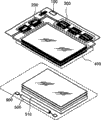
Fig. 1 represents the view of LCD according to an embodiment of the invention.
With reference to Fig. 1, LCD comprises according to an embodiment of the invention: a Liquid crystal module, and this assembly comprises: a liquid crystal board 400 that injects liquid crystal between double glazing; A driving circuit 200,300 that is used to drive liquid crystal board 400; A timing controller 100 is used to produce control signal, with control Driver Circuit 200,300; A backlight that comprises lamp 500; A reflecting plate 510; One lamp driver element 900 (being supply unit) is used for applying high voltage to drive lamp 500 to lamp 500.
Fig. 2 is the block scheme of LCD according to an embodiment of the invention;
With reference to Fig. 2, LCD comprises according to an embodiment of the invention: a timing controller 100; A control utmost point driver element 200; A data driver element 300; A liquid crystal board 400; A lamp 500; An inverter 600; A mode initialization unit 700 and an inverter control unit 800.
Specifically, supply unit is that lamp driver element 900 comprises according to an embodiment of the invention: inverter 600, mode initialization unit 700 and inverter control unit 800.
As shown in Figure 2, timing controller 100 receives rgb image signal R, G, B; Vertical synchronizing signal Vsync; Horizontal-drive signal Hsync; Master clock signal MCLK; Data are enabled (enable) signal DE; Reach uniformity signal (not shown) from the external image controller.For control chart picture signals R, G, B, timing controller produces first to the 3rd timing signal C1, C2, C3 based on level and vertical synchronizing signal Vsync, Hsync.The first timing signal C1 that is produced exports control utmost point driver element 200 to; The second timing signal C2 that is produced exports data-driven unit 300 to picture intelligence R, G, B; The 3rd timing signal C3 that is produced exports inverter control unit 800 to.
Herein, the first timing signal C1 comprises: a control utmost point selection signal CPV who is used to control output control utmost point on/off signal; One is used to select vertical synchronization enabling signal STV and an output of the first control polar curve to enable signal OE.
In addition, second timing signal C2 comprises: a load signal TP is used for after sending picture intelligence R, G, B the output of the IC of log-on data driver element (integrating network); One is used to notify control horizontal synchronization enabling signal STH and a data select signal HCLK that polar curve starts.
In the present embodiment, best the 3rd timing signal C3 is the first timing signal C1 the control utmost point is selected signal CPV; It is signal with horizontal-drive signal Hsync same frequency that the control utmost point is selected signal CPV.
Control utmost point driver element 200 receives that the control utmost points are selected signal CPV and from the vertical synchronization enabling signal STV of timing controller 100, and a plurality of control polar curves that sequentially form on LCD panel 400 apply a plurality of on/off control utmost point signal G1, G2......Gn.
Data-driven unit 300 receives picture intelligence R, G, the B from timing controller 100 and store these picture intelligences in the shift register (not shown).When usage level synchronous enabling signal STH, data-driven unit 300 is converted to relevant voltage with picture intelligence, and the associated voltage after will changing is applied on many data lines that form on the liquid crystal board 400.Controlling the moment that each corresponding horizontal synchronization enabling signal STH of polar curve imports with first to last one, data-driven unit 300 provides correlogram picture signals R, G, B to LCD panel 400.
LCD panel 400 comprises a plurality of m, x, n matrix form pixel electrode.When from control utmost point on/off (on/off) the signal G1 of control utmost point driver element 200, when G2......Gn is applied to pixel, LCD panel 400 drives this integrated related pixel electrode so that displayed image in response to the data power supply D1, the D2.....Dn that are provided by data-driven unit 300.
Lamp 500 provides required light to the LCD panel back.Usually be extensive use of EEFLS (external electrode fluorescent lamp), also can use CCFLS (cold-cathode fluorescence lamp).
As above-mentioned, power supply 900 comprises according to an embodiment of the invention: inverter 600; Mode initialization unit 700 and conversion control module 800.Specifically, inverter 600 will be converted to alternating voltage by the DC voltage that external power source comes, and be used to drive lamp 500 and export this alternating voltage.Also will do detailed description later on to this.
The mode initialization unit 700 that uses in LCD is differentiated dynamic image pattern and still image pattern when TV and monitor comprehensively use, to the still image pattern, export a high level " 1 ", to the dynamic image pattern, export a low level " 0 ", then distinguishing signal is put on conversion control module 800, this will describe afterwards.Here, the dynamic image pattern is corresponding to a pattern that wherein shows dynamic image, as when LCD of the present invention is used as television product; And the still image pattern is corresponding to a pattern that wherein mainly shows still image, as when LCD of the present invention is used as the monitor class product.
In addition, it can be about to mode initialization unit 700 according to a kind of like this mode and is included in the timing controller 100 and realizes.
In response to " 1 " or " 0 " control signal from mode initialization unit 700, inverter control unit 800 can be by applying to inverter 600 or stoping the 3rd timing signal C3 to come control operation inverter 600 under synchronous or asynchronous mode.
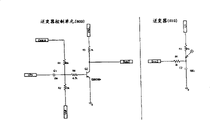
Fig. 3 represents the synoptic diagram of inverter control unit according to an embodiment of the invention;
As shown in Figure 3, inverter control unit 800 of the present invention is in response to the control signal gauge tap triode Q2 from mode initialization unit 700, to control applying of the 3rd timing signal CPV.When control signal was " 1 ", switch triode Q2 had entered effect (active) state, and the 3rd timing signal CPV is by switch triode Q2 input, as the synchronizing signal Sync2 that is used to drive inverter 600 under synchronous mode.Yet when control signal was " 0 ", Q2 was turned off, and therefore, the 3rd timing signal CPV just is not applied to inverter 600.
Fig. 4 represents the block scheme of inverter according to an embodiment of the invention.According to inverter according to the present invention 600 according to from the control signal of inverter control unit 800 with synchronous or operate in asynchronous mode.Referring to Fig. 4, inverter 600 comprises: a switchgear 620 that is used for outside DC voltage is changed to alternating voltage; One is used for boosted voltage and this voltage is applied to transformer 630 and a controller 610 that is used for gauge tap device 620 switching timing on the lamp 500 by switchgear 620.
Under synchronous mode, synchronizing signal Sync2 is applied on the controller 610, and this controller is again in response to the synchronizing signal Sync2 gauge tap device 620 that applies, so that be applied to the electric voltage frequency on the lamp and the horizontal-drive signal Frequency Synchronization of Liquid crystal module.
Fig. 5 represents the oscillogram of the electric current of the output voltage of each several part in the inverter shown in Figure 4 and lamp respectively.Specifically, Fig. 5 has represented that inverter 600 is operated in synchronously and each waveform under asynchronous two kinds of patterns.
Referring to Fig. 2,4,5, under the still image pattern, mode initialization unit 700 output high level signals " 1 ", and this control signal put on inverter control unit 800, inverter control unit 800 again in the future the timing signal C3 of self-timing controller 100 put on controller 610 on the inverter 600, so inverter 600 works in synchronous mode.
Under the dynamic image pattern, mode initialization unit 700 output low level signals " 0 ", and this control signal put on inverter control unit 800, the timing signal C3 of self-timing controller 100 is not applied on the inverter 600 in the future, so inverter 600 works in asynchronous mode.
As shown in Figure 5, when inverter 600 worked in synchronous mode, lamp current frequency was identical with the timing signal C3 frequency that is applied.The control utmost point selects signal CPV to use as synchronizing signal usually, and is preferably identical with horizontal-drive signal Hsync frequency.
The driving method of LCD is according to an embodiment of the invention below described.
Fig. 6 is a process flow diagram of representing to be used to according to an embodiment of the invention to drive the method for LCD.
As shown in Figure 6, need determine that at first this LCD is used for dynamic image or is used for still image pattern (S100)
At this, the dynamic image pattern is corresponding to a pattern that wherein shows dynamic image, as when LCD of the present invention is used as television product; And the still image pattern is corresponding to a pattern that wherein mainly shows still image, as when LCD of the present invention is used as the monitor class product.
Then, differentiate it is dynamic image or still image pattern by mode initialization unit 700, as be the still image pattern, then export one first level controling signal " 1 "; As be the dynamic image pattern, then export one second level controling signal " 0 " (200).(for example, first level and second level controling signal can be set at " 1 " respectively and reach " 0 ").
Then, as apply first level controling signal " 1 ", conversion control module 800 applies the timing signal CPV (S400) that receives from timing controller 100 to inverter 600, and then inverter 600 drives lamp 500 (S500) with synchronous mode.
On the other hand, as apply second level controling signal " 0 ", then inverter control unit 800 does not apply the timing signal CPV that receives from timing controller 100 to inverter 600, and therefore, inverter 600 can drive lamp (S300) with asynchronous mode.
As mentioned above, owing to always show dynamic image on the LCD panel in the dynamic image pattern, human eye is not easy to experience the Morie fringe phenomenon, and in the still image pattern, when most of still image shows, just experiences the Morie fringe phenomenon easily.
Therefore, according to the present invention, by just can eliminating Morie fringe phenomenon under the still image pattern to drive lamp with the synchronous mode of horizontal-drive signal, and by eliminating the luminous abnormal problem of lamp under the dynamic image pattern by inverter self frequency drives lamp.
In addition, because configuration of the present invention makes that inverter can be operated under the synchronous mode or be operated under the asynchronous mode according to the LCD switch mode, just can eliminate the Morie fringe phenomenon that may occur on the LCDs, and can solve the luminous abnormal problem of lamp.
Though described the present invention in conjunction with the preferred embodiments of the present invention, clearly, concerning technician in the art, under the situation that does not break away from scope of the present invention defined by the appended claims and design, can carry out various changes and modifications.
For example, though the control utmost point selects signal CPV to be used as the synchronizing signal of inverter, also can use level or vertical synchronizing signal Hsync or Vsync to replace.In addition, can generate and use other additional signals of the synchronizing signal that is used for inverter that is different from existing signal.