CN100440373C - Thin-film magnetic storage device capable of reading data in a self-reference manner - Google Patents
Thin-film magnetic storage device capable of reading data in a self-reference manner Download PDFInfo
- Publication number
- CN100440373C CN100440373C CNB031066313A CN03106631A CN100440373C CN 100440373 C CN100440373 C CN 100440373C CN B031066313 A CNB031066313 A CN B031066313A CN 03106631 A CN03106631 A CN 03106631A CN 100440373 C CN100440373 C CN 100440373C
- Authority
- CN
- China
- Prior art keywords
- data
- voltage
- memory cell
- read
- magnetic field
- Prior art date
- Legal status (The legal status is an assumption and is not a legal conclusion. Google has not performed a legal analysis and makes no representation as to the accuracy of the status listed.)
- Expired - Fee Related
Links
Images


Classifications
-
- G—PHYSICS
- G11—INFORMATION STORAGE
- G11C—STATIC STORES
- G11C11/00—Digital stores characterised by the use of particular electric or magnetic storage elements; Storage elements therefor
- G11C11/02—Digital stores characterised by the use of particular electric or magnetic storage elements; Storage elements therefor using magnetic elements
- G11C11/14—Digital stores characterised by the use of particular electric or magnetic storage elements; Storage elements therefor using magnetic elements using thin-film elements
- G11C11/15—Digital stores characterised by the use of particular electric or magnetic storage elements; Storage elements therefor using magnetic elements using thin-film elements using multiple magnetic layers
-
- G—PHYSICS
- G11—INFORMATION STORAGE
- G11C—STATIC STORES
- G11C7/00—Arrangements for writing information into, or reading information out from, a digital store
- G11C7/10—Input/output [I/O] data interface arrangements, e.g. I/O data control circuits, I/O data buffers
- G11C7/1051—Data output circuits, e.g. read-out amplifiers, data output buffers, data output registers, data output level conversion circuits
-
- G—PHYSICS
- G11—INFORMATION STORAGE
- G11C—STATIC STORES
- G11C11/00—Digital stores characterised by the use of particular electric or magnetic storage elements; Storage elements therefor
- G11C11/02—Digital stores characterised by the use of particular electric or magnetic storage elements; Storage elements therefor using magnetic elements
- G11C11/16—Digital stores characterised by the use of particular electric or magnetic storage elements; Storage elements therefor using magnetic elements using elements in which the storage effect is based on magnetic spin effect
- G11C11/165—Auxiliary circuits
- G11C11/1673—Reading or sensing circuits or methods
-
- G—PHYSICS
- G11—INFORMATION STORAGE
- G11C—STATIC STORES
- G11C29/00—Checking stores for correct operation ; Subsequent repair; Testing stores during standby or offline operation
- G11C29/02—Detection or location of defective auxiliary circuits, e.g. defective refresh counters
-
- G—PHYSICS
- G11—INFORMATION STORAGE
- G11C—STATIC STORES
- G11C29/00—Checking stores for correct operation ; Subsequent repair; Testing stores during standby or offline operation
- G11C29/02—Detection or location of defective auxiliary circuits, e.g. defective refresh counters
- G11C29/026—Detection or location of defective auxiliary circuits, e.g. defective refresh counters in sense amplifiers
-
- G—PHYSICS
- G11—INFORMATION STORAGE
- G11C—STATIC STORES
- G11C29/00—Checking stores for correct operation ; Subsequent repair; Testing stores during standby or offline operation
- G11C29/02—Detection or location of defective auxiliary circuits, e.g. defective refresh counters
- G11C29/028—Detection or location of defective auxiliary circuits, e.g. defective refresh counters with adaption or trimming of parameters
-
- G—PHYSICS
- G11—INFORMATION STORAGE
- G11C—STATIC STORES
- G11C7/00—Arrangements for writing information into, or reading information out from, a digital store
- G11C7/06—Sense amplifiers; Associated circuits, e.g. timing or triggering circuits
Landscapes
- Engineering & Computer Science (AREA)
- Computer Hardware Design (AREA)
- Mram Or Spin Memory Techniques (AREA)
- Hall/Mr Elements (AREA)
- Semiconductor Memories (AREA)
Abstract
数据读出时,来自电流供给晶体管(105)的电流通过选择存储单元及数据线(DIO)。另外,不破坏存储数据的电平大小的偏磁场被加在选择存储单元上。通过施加偏磁场,用读出放大器(120)放大选择存储单元的电阻对应于存储数据电平的极性变化前后的数据线电压差,只对选择存储单元进行存取,进行数据读出。另外,由于在数据线(DIO)和读出放大器(120)之间用电容器(110)进行绝缘,所以能与存储单元的磁化特性隔离,使读出放大器在最佳输入电压范围内工作。
When data is read, the current from the current supply transistor (105) passes through the selected memory cell and the data line (DIO). In addition, a bias magnetic field of a level that does not destroy stored data is applied to the selected memory cell. By applying a bias magnetic field, the sense amplifier (120) amplifies the data line voltage difference before and after the polarity change of the resistance of the selected memory cell corresponding to the stored data level, and only the selected memory cell is accessed to read data. In addition, since the capacitor (110) is used for insulation between the data line (DIO) and the sense amplifier (120), it can be isolated from the magnetization characteristics of the memory cell, so that the sense amplifier can operate in an optimum input voltage range.
Description
技术领域 technical field
本发明涉及薄膜磁性体存储装置,特别是涉及备有磁隧道结(MTJ:Magnetic Tunnel Junction)的存储单元的随机存取存储器。The present invention relates to a thin film magnetic memory device, and more particularly to a random access memory having a memory cell of a Magnetic Tunnel Junction (MTJ: Magnetic Tunnel Junction).
背景技术 Background technique
作为能用低功耗进行非易失性的数据的存储的存储装置,MRAM(Magnetic Random Access Memory)装置引人注目。MRAM装置是一种用在半导体集成电路中形成的多个薄膜磁性体进行非易失性的数据存储的、对各个薄膜磁性体能进行随机存取的存储装置。MRAM (Magnetic Random Access Memory) devices are attracting attention as storage devices that can store nonvolatile data with low power consumption. The MRAM device is a memory device that stores nonvolatile data using a plurality of thin-film magnetic bodies formed in a semiconductor integrated circuit, and can perform random access to each thin-film magnetic body.
特别是近年来,表明通过将利用磁隧道结的薄膜磁性体作为存储单元用,MRAM的性能飞快地进步。在“A 10ns Read and WriteNon-Volatile Memory Array Using a Magnetic TunnelJunction and FET Switch in each Cell”,ISSCC Digestof Technical Papers,TA7.2,Feb.2000.及“Nonvolatile RAMbased on Magnetic Tunnel Junction Elements”,ISSCCDigest of Technical Papers,TA7.3,Feb.2000.等技术文献中公开了备有具有磁隧道结的存储单元的MRAM装置。In particular, in recent years, it has been shown that the performance of MRAMs has rapidly improved by using thin-film magnetic materials utilizing magnetic tunnel junctions for memory cells. In "A 10ns Read and WriteNon-Volatile Memory Array Using a Magnetic TunnelJunction and FET Switch in each Cell", ISSCC Digestof Technical Papers, TA7.2, Feb.2000. and "Nonvolatile RAMbased on Magnetic Tunnel CD Junction of Techical SCElements", Papers, TA7.3, Feb. 2000. and other technical documents disclose MRAM devices equipped with memory cells having magnetic tunnel junctions.
图11是表示有磁隧道结部分的存储单元(以下简称“MTJ存储单元”)的结构的示意图。FIG. 11 is a schematic diagram showing the structure of a memory cell having a magnetic tunnel junction portion (hereinafter referred to as "MTJ memory cell").
参照图11,MTJ存储单元包括电阻随着磁性写入的存储数据的电平的不同而变化的隧道磁阻元件TMR、以及存取晶体管ATR。存取晶体管ATR与隧道磁阻元件TMR串联连接在写入位线WBL及读出位线RBL之间。作为存取晶体管ATR,具有代表性地能采用在半导体基板上形成的场效应型晶体管。Referring to FIG. 11 , the MTJ memory cell includes a tunnel magnetoresistive element TMR whose resistance varies with the level of magnetically written storage data, and an access transistor ATR. Access transistor ATR and tunnel magnetoresistive element TMR are connected in series between write bit line WBL and read bit line RBL. As the access transistor ATR, typically, a field effect transistor formed on a semiconductor substrate can be used.
对MTJ存储单元设有:数据写入时分别流过不同方向的数据写入电流用的写入位线WBL及写入数位线WDL;指示数据读出用的字线WL;以及接收数据读出电流的供给的读出位线RBL。数据读出时,隧道磁阻元件TMR响应存取晶体管ATR的导通,将设定为接地电压的写入位线WRL和读出位线RBL之间导电性地耦合起来。The MTJ memory cell is provided with: the write bit line WBL and the write digit line WDL for data write current flowing in different directions when data is written; the word line WL for indicating data read; and the receive data read current supply to the read bit line RBL. During data reading, the tunnel magnetoresistive element TMR electrically couples the write bit line WRL set to the ground voltage and the read bit line RBL in response to the conduction of the access transistor ATR.
图12是说明对MJT存储单元的数据写入工作的示意图。FIG. 12 is a schematic diagram illustrating an operation of writing data into an MJT memory cell.
参照图12,隧道磁阻元件TMR有:有固定的磁化方向一定的强磁性体层(以下简称“固定磁化层”)FL;以及沿着对应于外部的施加磁场的方向磁化的强磁性体层(以下简称“自由磁化层)VL。在固定磁化层FL和自由磁化层VL之间设有由绝缘体膜形成的隧道阻挡层(隧道膜)TB。自由磁化层VL根据写入的存储数据的电平,沿着与固定磁化层FL同一方向或与固定磁化层FL相反(反平行)方向磁化。由这些固定磁化层FL、隧道阻挡层TB及自由磁化层VL形成磁隧道结。Referring to FIG. 12, the tunnel magnetoresistive element TMR has: a ferromagnetic layer with a fixed magnetization direction (hereinafter referred to as "fixed magnetization layer") FL; and a ferromagnetic layer magnetized along a direction corresponding to an external applied magnetic field. (hereinafter referred to as "free magnetization layer) VL. A tunnel barrier layer (tunnel film) TB formed of an insulator film is provided between the fixed magnetization layer FL and the free magnetization layer VL. The free magnetization layer VL is Flat, magnetized in the same direction as the fixed magnetization layer FL or in the opposite (antiparallel) direction to the fixed magnetization layer FL. These fixed magnetization layer FL, tunnel barrier layer TB and free magnetization layer VL form a magnetic tunnel junction.
隧道磁阻元件TMR的电阻随着固定磁化层FL及自由磁化层VL各自的磁化方向的相对关系的变化而变化。具体地说,隧道磁阻元件TMR的电阻在固定磁化层FL的磁化方向和自由磁化层VL的磁化方向平行的情况下达到最小值Rmin,在两者的磁化方向呈相反(反平行)方向的情况下达到最大值Rmax。The resistance of the tunnel magneto-resistive element TMR changes with changes in the relative relationship between the magnetization directions of the fixed magnetization layer FL and the free magnetization layer VL. Specifically, the resistance of the tunnel magnetoresistive element TMR reaches the minimum value Rmin when the magnetization direction of the fixed magnetization layer FL is parallel to that of the free magnetization layer VL, and when the magnetization directions of the two are in opposite (antiparallel) directions Under the circumstances, the maximum value Rmax is reached.
数据写入时,字线WL不被激活,存取晶体管ATR被阻断。在该状态下,使自由磁化层VL磁化用的数据写入电流在写入位线WBL及写入数位线WDL中分别沿着对应于写入数据的电平的方向流过。When writing data, the word line WL is not activated, and the access transistor ATR is blocked. In this state, a data write current for magnetizing free magnetization layer VL flows through write bit line WBL and write digit line WDL in directions corresponding to the levels of write data.
图13是表示数据写入时的数据写入电流和隧道磁阻元件的磁化方向的关系的示意图。13 is a schematic diagram showing the relationship between the data writing current and the magnetization direction of the tunnel magnetoresistive element during data writing.
参照图13,横轴H(EA)表示在隧道磁阻元件TMR内的自由磁化层VL中沿着易磁化轴(EA:Easy Axis)方向施加的磁场。另一方面,纵轴H(HA)表示在自由磁化层VL中沿着难磁化轴(HA:HardAxis)方向作用的磁场。磁场H(EA)及H(HA)分别对应于由分别流过写入位线WBL及写入数位线WDL的电流产生的两个磁场。Referring to FIG. 13 , the horizontal axis H(EA) represents a magnetic field applied in the direction of the easy axis (EA: Easy Axis) in the free magnetization layer VL in the tunnel magnetoresistive element TMR. On the other hand, the vertical axis H (HA) represents a magnetic field acting in the direction of the hard axis (HA: Hard Axis) in the free magnetization layer VL. Magnetic fields H(EA) and H(HA) respectively correspond to two magnetic fields generated by current flowing through write bit line WBL and write digit line WDL, respectively.
在MTJ存储单元中,固定磁化层FL的固定磁化方向沿着自由磁化层VL的易磁化轴方向,自由磁化层VL根据存储数据的电平(“1”及“0”),沿着易磁化轴方向、即沿着与固定磁化层FL平行或反平行(相反)方向磁化。MTJ存储单元与自由磁化层VL的两种磁化方向对应,能存储1位的数据(“1”或“0”)。In the MTJ memory cell, the fixed magnetization direction of the fixed magnetization layer FL is along the easy magnetization axis direction of the free magnetization layer VL, and the free magnetization layer VL is along the easy magnetization axis according to the level of the stored data ("1" and "0") It is magnetized in the axial direction, that is, in a direction parallel or antiparallel (opposite) to the fixed magnetization layer FL. The MTJ memory cell corresponds to two magnetization directions of the free magnetization layer VL, and can store 1-bit data (“1” or “0”).
自由磁化层VL的磁化方向为施加的磁场H(EA)及H(HA)的和,但在到达图中所示的星形特性曲线的外侧的情况下,能重新改写。即,在施加的数据写入磁场相当于星形特性曲线的内侧区域的强度的情况下,自由磁化层VL的磁化方向不变化。The magnetization direction of the free magnetization layer VL is the sum of the applied magnetic fields H(EA) and H(HA), but can be rewritten when it reaches the outside of the star-shaped characteristic curve shown in the figure. That is, when the applied data writing magnetic field has a strength corresponding to the inner region of the star-shaped characteristic curve, the magnetization direction of the free magnetization layer VL does not change.
如星形特性曲线所示,通过对自由磁化层VL施加难磁化轴方向的磁场,能使改变沿易磁化轴的磁化方向所需要的磁化阈值下降。As shown by the star-shaped characteristic curve, by applying a magnetic field in the direction of the hard axis to the free magnetization layer VL, the magnetization threshold required to change the magnetization direction along the easy axis can be lowered.
如图13中的例所示,在设计了数据写入时的工作点的情况下,在作为数据写入对象的MTJ存储单元中,易磁化轴方向的数据写入磁场的强度被设计为HWR。即,为了获得该数据写入磁场HWR,设计流过写入位线WBL或写入数位线WDL的数据写入电流的值。一般说来,数据写入磁场HWR用磁化方向的切换所必要的切换磁场HSW和容限部分ΔH的和表示。即HWR=HSW+ΔH。As shown in the example in FIG. 13, in the case where the operating point at the time of data writing is designed, in the MTJ memory cell as the object of data writing, the strength of the data writing magnetic field in the direction of the easy axis of magnetization is designed to be H WR . That is, in order to obtain this data write magnetic field H WR , the value of the data write current flowing through write bit line WBL or write digit line WDL is designed. In general, the data writing magnetic field H WR is represented by the sum of the switching magnetic field H SW necessary for switching the magnetization direction and the margin portion ΔH. That is, H WR =H SW +ΔH.
为了改写MTJ存储单元的存储数据、即为了改写隧道磁阻元件TMR的磁化方向,在写入数位线WDL和写入位线WBL两者中流过规定电平以上的数据写入电流。因此,隧道磁阻元件TMR中的自由磁化层VL根据沿易磁化轴(EH)的数据写入磁场的方向,沿着与固定磁化层FL平行或相反(反平行)方向磁化。在隧道磁阻元件TMR中暂时写入的磁化方向、即MTJ存储单元的存储数据在进行新的数据写入之前的期间不易失地被保持着。In order to rewrite stored data in the MTJ memory cell, that is, to rewrite the magnetization direction of the tunnel magnetoresistive element TMR, a data write current of a predetermined level or higher flows through both write digit line WDL and write bit line WBL. Therefore, the free magnetization layer VL in the tunnel magnetoresistive element TMR is magnetized in parallel or opposite (antiparallel) direction to the fixed magnetization layer FL according to the direction of the data writing magnetic field along the easy axis (EH). The magnetization direction once written in the tunnel magnetoresistive element TMR, that is, the storage data of the MTJ memory cell is held in a non-volatile manner until new data is written.
图14是说明从MTJ存储单元读出数据的示意图。FIG. 14 is a schematic diagram illustrating reading data from an MTJ memory cell.
参照图14,在数据读出时,存取晶体管ATR响应字线WL的激活而导通。另外,写入位线WBL被设定为接地电压GND。因此,隧道磁阻元件TMR在被接地电压GND下拉的状态下,与读出位线RBL导电性地耦合。Referring to FIG. 14, at the time of data readout, the access transistor ATR is turned on in response to the activation of the word line WL. In addition, write bit line WBL is set to ground voltage GND. Therefore, the tunnel magnetoresistive element TMR is electrically coupled to the read bit line RBL while being pulled down by the ground voltage GND.
在此状态下,如果用规定电压上拉读出位线RBL,则对应于隧道磁阻元件TMR的电阻的、即对应于MTJ存储单元的存储数据电平的存储单元电流Icell流过包括读出位线RBL及隧道磁阻元件TMR的电流路径。例如,通过将该存储单元电流Icell与规定的基准电流比较,能从MTJ存储单元读出存储数据。In this state, if the read bit line RBL is pulled up with a predetermined voltage, the memory cell current Icell corresponding to the resistance of the tunnel magnetoresistive element TMR, that is, corresponding to the storage data level of the MTJ memory cell flows through the A current path of the bit line RBL and the tunnel magnetoresistive element TMR. For example, by comparing the memory cell current Icell with a predetermined reference current, stored data can be read from the MTJ memory cell.
这样由于隧道磁阻元件TMR根据施加的数据写入磁场,按照能改写的磁化方向改变其电阻,所以通过分别与隧道磁阻元件TMR的电阻Rmax/Rmin、以及存储数据的电平(“1”/“0”)相对应,能进行非易失的数据存储。这样,在MRAM装置中,利用隧道磁阻元件TMR中的对应于存储数据电平的不同的耦合电阻的差(ΔR=Rmax-Rmin),进行数据存储。In this way, since the tunnel magnetoresistance element TMR changes its resistance according to the rewritable magnetization direction according to the applied data writing magnetic field, the resistance Rmax/Rmin of the tunnel magnetoresistance element TMR and the level of the stored data ("1" /"0") corresponding to non-volatile data storage. In this way, in the MRAM device, data storage is performed using the difference (ΔR=Rmax−Rmin) between the different coupling resistances in the tunnel magnetoresistive element TMR corresponding to the storage data level.
一般说来,与进行数据存储用的正规的MTJ存储单元不同,设有生成与存储单元电流Icell进行比较的基准电流用的基准单元。由基准单元生成的基准电流需要这样设计,即该基准电流为分别对应于MTJ存储单元的两种电阻Rmax及Rmin的两种存储单元电流Icell的中间值。基本上包括与正规的MTJ存储单元同样的隧道磁阻元件TMR,设计这些基准单元。In general, unlike a normal MTJ memory cell for storing data, a reference cell for generating a reference current to be compared with the memory cell current Icell is provided. The reference current generated by the reference unit needs to be designed in such a way that the reference current is the middle value of the two memory cell currents Icell respectively corresponding to the two resistances Rmax and Rmin of the MTJ memory cell. Basically, these reference cells are designed to include the same tunnel magneto-resistance element TMR as a regular MTJ memory cell.
流过隧道磁阻元件TMR的电流受作为隧道膜用的绝缘膜的厚度大小的影响。因此,如果在正规的MTJ存储单元及基准单元之间实际隧道膜厚度产生差异,则基准电流就不能设计成所希望的电平。根据该理由,难以将用基准单元生成的基准电流的电平准确地设定成能检测上述的微小电流差的电平,由于基准电流的离散,数据读出精度有可能下降。The current flowing through the tunnel magnetoresistive element TMR is affected by the thickness of the insulating film used as the tunnel film. Therefore, if there is a difference in actual tunnel film thickness between the normal MTJ memory cell and the reference cell, the reference current cannot be designed to a desired level. For this reason, it is difficult to accurately set the level of the reference current generated by the reference cell to a level capable of detecting the above-mentioned small current difference, and the accuracy of data reading may decrease due to the variation of the reference current.
特别是在一般的MTJ存储单元中,根据存储数据电平产生的电阻差ΔR不会那么大。具有代表性的是电阻Rmin限于Rmax的百分之数十左右。因此,对应于存储数据电平的存储单元电流Icell的变化也不那么大,只限于微安(μA:10-6A)数量级大小。因此,有必要使正规的MTJ存储单元及基准单元的隧道膜厚度的制造工序高精度化。Especially in a general MTJ memory cell, the resistance difference [Delta]R generated according to the stored data level is not so large. Typically, the resistance Rmin is limited to about tens of percent of Rmax. Therefore, the change of the memory cell current Icell corresponding to the stored data level is not so large, and is limited to the order of magnitude of microamperes (μA: 10 -6 A). Therefore, it is necessary to increase the precision of the manufacturing process of the thickness of the tunnel film of the normal MTJ memory cell and the reference cell.
可是,如果使制造工艺中的隧道膜厚度的精度严格化,则有可能由于产品的合格率下降等引起制造成本的上升。从这样的背景出发,在MRAM装置中,要求不导致制造工序的严格化、而能高精度地进行基于MTJ存储单元中的上述的电阻差ΔR的数据读出的结构。However, if the accuracy of the thickness of the tunnel film in the manufacturing process is made strict, there is a possibility that the manufacturing cost will increase due to a reduction in the yield of the product or the like. From such a background, an MRAM device is required to have a structure capable of accurately performing data reading based on the above-mentioned resistance difference ΔR in the MTJ memory cell without intensifying the manufacturing process.
为了解决这样的问题,美国专利第6,317,376B1号中公开了一种不用基准单元、而只通过对选择存储单元的存取,进行数据的读出的所谓“自基准方式”的数据读出的MRAM装置的结构。In order to solve such a problem, U.S. Patent No. 6,317,376B1 discloses a MRAM in which data is read out in a so-called "self-reference mode" by only accessing selected memory cells without reference cells. The structure of the device.
在该美国专利中公开的现有的自基准读出中,一次数据读出工作由以下过程构成:(1)从选择存储单元读出存储数据,(2)读出对该选择存储单元进行了“0”数据的强制写入后的数据,(3)读出对该选择存储单元进行了“1”数据的强制写入后的数据,(4)根据上述(1)~(3)的读出结果生成读出数据,以及(5)将读出数据再写入该选择存储单元(恢复)。如果采用这样的数据读出工作,则由于只对选择存储单元进行存取,就能进行数据读出,所以不会受基准单元的制造离散的影响,能进行高精度的数据读出。In the existing self-reference readout disclosed in this U.S. patent, a data readout operation consists of the following processes: (1) read out stored data from the selected memory cell, (2) read out the selected memory cell (3) Read the data after forced writing of "1" data to the selected memory cell, (4) read according to the above (1)~(3) generate read data as a result, and (5) rewrite the read data to the selected memory cell (restore). According to such a data read operation, since data can be read only by accessing selected memory cells, high-precision data read can be performed without being affected by manufacturing variations of reference cells.
可是,在现有的自基准读出中,在一次数据读出工作中,由于需要反复进行强制的数据写入及数据读出、以及伴随破坏选择存储单元的存储数据而需要再写入,所以存在妨碍数据读出工作的高速化的问题。However, in the existing self-reference read, in one data read operation, due to the need to repeatedly perform forced data writing and data reading, and the need to rewrite accompanying the destruction of the stored data in the selected memory cell, There is a problem of hindering the speed-up of the data reading operation.
发明内容 Contents of the invention
本发明的目的在于提供一种基于自基准方式的进行高速及高精度的数据读出的薄膜磁性体存储装置的结构。An object of the present invention is to provide a structure of a thin-film magnetic storage device capable of high-speed and high-precision data reading by a self-reference method.
摘要地说本发明是一种薄膜磁性体存储装置,其特征在于:备有以下部分,分别使对应于磁性写入的存储数据的方向沿着易磁化轴磁化,有对应于磁化方向的电阻的多个存储单元;在数据读出时,通过上述多个存储单元中的被选择为数据读出对象的选择存储单元,与固定电压进行电气耦合的数据线;至少在上述数据读出时将上述数据线与第一规定电压耦合的电流供给电路;对上述选择存储单元施加沿着难磁化轴的偏磁场用的偏磁场施加单元;上述数据读出时,根据对上述选择存储单元施加上述偏磁场前后的上述数据线的电压,生成对应于上述选择存储单元的存储数据的读出数据的数据读出电路;上述数据读出电路包括设置在第一读出输入结点和上述数据线之间,将上述偏磁场的施加前后上述数据线的电压变化传递给上述第一读出输入结点用的耦合电容;上述数据读出时,在施加上述偏磁场之前将第二读出输入结点的电压设定为与上述第一读出输入结点相同的电平用的电压传递单元;保持上述第二读出输入结点的电压用的电压保持单元;放大上述第一及第二读出输入结点的电压差的第一电压放大器;以及上述数据读出时,根据上述偏磁场施加后的上述第一电压放大器的输出,生成上述读出数据的数据生成电路。In summary, the present invention is a thin-film magnetic storage device characterized in that it is equipped with the following parts, which respectively magnetize the direction corresponding to the stored data in magnetic writing along the easy axis of magnetization, and have resistance corresponding to the direction of magnetization. A plurality of memory cells; when data is read, a data line that is electrically coupled to a fixed voltage through a selected memory cell selected as a data read object among the plurality of memory cells; at least when the above data is read, the above-mentioned a current supply circuit for coupling the data line to a first predetermined voltage; a bias field applying unit for applying a bias field along the hard axis to the selected memory cell; The voltages of the above-mentioned data lines before and after generate a data readout circuit corresponding to the readout data of the storage data of the above-mentioned selected memory cells; the above-mentioned data readout circuit is included between the first readout input node and the above-mentioned data line, The voltage change of the above-mentioned data line before and after the application of the above-mentioned bias magnetic field is transmitted to the coupling capacitor for the above-mentioned first readout input node; when the above-mentioned data is read, the voltage of the second readout input node is transferred to A voltage transfer unit for setting the same level as the first readout input node; a voltage holding unit for maintaining the voltage of the second readout input node; amplifying the first and second readout input nodes A first voltage amplifier for the voltage difference between points; and a data generation circuit for generating the read data based on the output of the first voltage amplifier after the bias field is applied during the data read.
电压传递单元最好有:设置在与第一规定电压独立的第二规定电压和第一读出输入结点之间的第一开关;以及设置在第二读出输入结点和第一电压放大器的输出结点之间的第二开关,数据读出时,各个第一及第二开关在对选择存储单元施加偏磁场之前导通,在施加偏磁场之后阻断。Preferably, the voltage transfer unit has: a first switch provided between a second specified voltage independent of the first specified voltage and the first readout input node; and a first switch provided between the second readout input node and the first voltage amplifier The second switch between the output nodes of each of the first and second switches is turned on before the bias magnetic field is applied to the selected memory cell during data reading, and is blocked after the bias magnetic field is applied.
因此,本发明的主要优点是:通过施加沿难磁化轴方向的偏磁场,使选择存储单元的电阻按照对应于存储数据的极性变化(增加或减少),利用这样的变化,只对选择存储单元进行存取,而不伴随强制的数据写入及数据读出、以及对选择存储单元的存储数据的再写入,能高速地进行自基准方式的数据读出。Therefore, the main advantage of the present invention is: by applying a bias field along the hard axis direction, the resistance of the selected memory cell is changed (increased or decreased) according to the polarity corresponding to the stored data, and by using such a change, only the selected memory cell Cell access is performed without forced data writing and data reading and rewriting of stored data in selected memory cells, and data reading from the reference method can be performed at high speed.
另外,使数据线的预充电电压(第一规定电压)和施加偏磁场之前的平衡状态下的第一及第二读出输入结点的预充电电压(第二规定电压)互相独立,能分别对其进行最佳设定。因此,能将数据线的预充电电压设定成考虑了存储单元的MR特性的最佳电平,另一方面,能与其独立地将第一及第二读出输入结点的预充电电压设定成能确保读出放大器的工作容限的电平。In addition, the precharge voltage (first predetermined voltage) of the data line and the precharge voltage (second predetermined voltage) of the first and second read input nodes in the equilibrium state before applying the bias magnetic field are independent from each other, and can be respectively Make the best settings for it. Therefore, the precharge voltage of the data line can be set to an optimum level considering the MR characteristic of the memory cell, and on the other hand, the precharge voltage of the first and second sense input nodes can be set independently of it. The level is set to ensure the operating margin of the sense amplifier.
从另一方面来说,本发明是一种薄膜磁性体存储装置,其特征在于:备有以下部分,使对应于磁性写入的存储数据的方向沿着易磁化轴磁化,有对应于磁化方向的电阻的多个存储单元;数据读出时,通过上述多个存储单元中的被选择为数据读出对象的选择存储单元,与固定电压进行电气耦合的数据线;至少在上述数据读出时,将上述数据线与规定电压耦合的电流供给电路;上述数据读出时对上述选择存储单元施加沿着难磁化轴的偏磁场,同时数据写入时对成为数据写入对象的存储单元施加沿着上述难磁化轴的数据写入磁场用的偏磁场施加单元;上述偏磁场施加单元包括分别设置在上述多个存储单元的每个规定区中,有选择地接收对各个对应的上述存储单元施加沿上述难磁化轴方向的磁场用的电流的供给的多条写入数位线;分别对应于上述多条写入数位线设置,在第一及第二电压之间与上述多条写入数位线中的对应的一条写入数位线串联连接的多个驱动晶体管;以及分别对应于上述多条写入数位线设置、分别控制上述多个驱动晶体管中的对应的一个通·断用的写入数位线驱动控制单元,各上述多个写入数位线驱动控制单元有根据表示上述对应的一条写入数位线是否对应于上述选择存储单元的地址信息,控制上述驱动晶体管的驱动电流用的逻辑电路,上述逻辑电路使上述驱动电流在上述数据读出时比上述数据写入时变化得缓慢,数据读出电路在上述数据读出时,根据对上述选择存储单元施加偏磁场前后的上述数据线的电压,生成对应于上述选择存储单元的存储数据的读出数据。From another aspect, the present invention is a thin-film magnetic storage device, characterized in that it is equipped with the following part, which magnetizes the direction corresponding to the stored data in the magnetic writing along the easy magnetization axis, and has a magnetization direction corresponding to the magnetization direction. multiple memory cells with resistance; when data is read, a data line that is electrically coupled with a fixed voltage through the selected memory cell selected as the data read object among the above multiple memory cells; at least when the above data is read , a current supply circuit that couples the data line to a predetermined voltage; when the data is read, a bias field along the hard axis is applied to the selected memory cell, and at the same time, when the data is written, an edge is applied to the memory cell that is the object of data writing. A biasing field applying unit for the data writing magnetic field along the above-mentioned hard axis; the above-mentioned biasing field applying unit is respectively arranged in each predetermined area of the above-mentioned plurality of memory cells, and selectively receives and applies to each corresponding above-mentioned memory cell. A plurality of writing digit lines for the supply of current for the magnetic field along the direction of the hard axis of magnetization; respectively corresponding to the plurality of writing digit lines, and between the first and second voltages and the plurality of writing digit lines A plurality of driving transistors connected in series to a corresponding one of the writing digit lines; A line drive control unit, each of the plurality of write digit line drive control units has a logic circuit for controlling the drive current of the drive transistor according to the address information indicating whether the corresponding write digit line corresponds to the selected memory unit, The logic circuit makes the driving current change more slowly during the data reading than during the data writing, and the data reading circuit changes the voltage of the data line before and after applying a bias magnetic field to the selected memory cell during the data reading. , generating readout data corresponding to the storage data of the above-mentioned selected memory cell.
这样的薄膜磁性体存储装置通过施加沿难磁化轴方向的偏磁场,使选择存储单元的电阻按照对应于存储数据的极性变化(增加或减少),利用这样的变化,只对选择存储单元进行存取,而不伴随强制的数据写入及数据读出、以及对选择存储单元的存储数据的再写入,能高速地进行自基准方式的数据读出。另外,由于能使发生偏磁场用的结构与数据写入时发生规定的数据写入磁场的结构共用,所以能简化电路结构。特别是由于缓慢地发生数据读出时的偏磁场,所以能避免数据线的电压急剧地变化,能进行降低了噪声的稳定的数据读出。Such a thin-film magnetic storage device applies a bias magnetic field along the hard axis direction to change (increase or decrease) the resistance of the selected memory cell according to the polarity corresponding to the stored data, and use such a change to only select the memory cell. Access can be performed at high speed from the reference method without forced data writing and data reading, and rewriting of stored data in selected memory cells. In addition, since the configuration for generating a bias magnetic field can be shared with the configuration for generating a predetermined data writing magnetic field during data writing, the circuit configuration can be simplified. In particular, since the bias magnetic field at the time of data reading is generated slowly, a sudden change in the voltage of the data line can be avoided, and stable data reading with reduced noise can be performed.
从另一方面来说,本发明是一种薄膜磁性体存储装置,其特征在于:备有以下部分,使对应于磁性写入的存储数据的方向沿着易磁化轴磁化,有对应于磁化方向的电阻的多个存储单元;数据读出时,通过上述多个存储单元中的被选择为数据读出对象的选择存储单元,与固定电压进行电气耦合的数据线;至少在上述数据读出时将上述数据线与规定电压耦合的电流供给电路;接收第一电源电压,数据写入时及数据读出时分别对选择存储单元施加沿着难磁化轴的规定磁场用的磁场施加单元;接收第二电源电压及上述固定电压,生成对应于上述选择存储单元的存储数据的读出数据的数据读出电路,上述第一电源电压和上述固定电压的差比上述第二电源电压和上述固定电压的差大。From another aspect, the present invention is a thin-film magnetic storage device, characterized in that it is equipped with the following part, which magnetizes the direction corresponding to the stored data in the magnetic writing along the easy magnetization axis, and has a magnetization direction corresponding to the magnetization direction. multiple memory cells with resistance; when data is read, a data line that is electrically coupled with a fixed voltage through the selected memory cell selected as the data read object among the above multiple memory cells; at least when the above data is read A current supply circuit that couples the data line to a predetermined voltage; receives the first power supply voltage, and applies a predetermined magnetic field along the hard axis to the selected memory cell during data writing and data reading; a magnetic field applying unit that receives the second power supply voltage. Two power supply voltages and the above-mentioned fixed voltage are used to generate a data readout circuit corresponding to the data stored in the selected memory cell, and the difference between the first power supply voltage and the above-mentioned fixed voltage is greater than the difference between the second power supply voltage and the above-mentioned fixed voltage. Big difference.
这样的薄膜磁性体存储装置通过施加沿难磁化轴方向的偏磁场,使选择存储单元的电阻按照对应于存储数据的极性变化(增加或减少),利用这样的变化,只对选择存储单元进行存取,而不伴随强制的数据写入及数据读出、以及对选择存储单元的存储数据的再写入,能高速地进行自基准方式的数据读出。另外,由于能使发生偏磁场用的结构与数据写入时发生规定的数据写入磁场的结构共用,所以能简化电路结构。特别是由于能用足够大的电位差驱动电流布线,所以能充分地供给发生偏磁场及数据写入磁场的电流。Such a thin-film magnetic storage device applies a bias magnetic field along the hard axis direction to change (increase or decrease) the resistance of the selected memory cell according to the polarity corresponding to the stored data, and use such a change to only select the memory cell. Access can be performed at high speed from the reference method without forced data writing and data reading, and rewriting of stored data in selected memory cells. In addition, since the configuration for generating a bias magnetic field can be shared with the configuration for generating a predetermined data writing magnetic field during data writing, the circuit configuration can be simplified. In particular, since the current wiring can be driven with a sufficiently large potential difference, a current for generating a bias magnetic field and a data writing magnetic field can be sufficiently supplied.
附图说明 Description of drawings
图1是表示本发明的实施例的MRAM装置的总体结构的简略框图。FIG. 1 is a schematic block diagram showing the overall configuration of an MRAM device according to an embodiment of the present invention.
图2是说明本发明的实施例的数据读出工作的原理用的示意图。Fig. 2 is a schematic diagram for explaining the principle of the data reading operation of the embodiment of the present invention.
图3是说明图2所示的各状态下的隧道磁阻元件的磁化方向的示意图。FIG. 3 is a schematic diagram illustrating the magnetization direction of the tunnel magnetoresistive element in each state shown in FIG. 2 .
图4是表示对存储器阵列10进行数据读出工作及数据写入工作用的电路组的实施例1的结构的电路图。FIG. 4 is a circuit diagram showing the configuration of a first embodiment of a circuit group for performing a data read operation and a data write operation to the
图5是表示图4所示的数据读出电路的主要部分的结构的电路图。FIG. 5 is a circuit diagram showing the configuration of main parts of the data readout circuit shown in FIG. 4 .
图6是说明本发明的实施例的数据读出工作的工作波形图。Fig. 6 is an operation waveform diagram illustrating the data readout operation of the embodiment of the present invention.
图7是表示实施例1的变形例的数据读出电路的主要部分的结构的电路图。7 is a circuit diagram showing the configuration of a main part of a data readout circuit according to a modification of the first embodiment.
图8是表示控制对写入数位线WDL的电流供给的电路组的实施例2的结构的电路图。FIG. 8 is a circuit diagram showing a configuration of a second embodiment of a circuit group for controlling current supply to write digit line WDL.
图9是表示控制对写入数位线WDL的电流供给的电路组的实施例2的变形例1的结构的电路图。9 is a circuit diagram showing the configuration of
图10是表示控制对写入数位线WDL的电流供给的电路组的实施例2的变形例2的结构的电路图。FIG. 10 is a circuit diagram showing the configuration of
图11是表示MTJ存储单元的结构的示意图。FIG. 11 is a schematic diagram showing the structure of an MTJ memory cell.
图12是说明对MTJ存储单元的数据写入工作的示意图。Fig. 12 is a schematic diagram illustrating the data writing operation to the MTJ memory cell.
图13是表示数据写入时的数据写入电流和隧道磁阻元件的磁化方向的关系的示意图。13 is a schematic diagram showing the relationship between the data writing current and the magnetization direction of the tunnel magnetoresistive element during data writing.
图14是说明从MTJ存储单元读出数据的示意图。FIG. 14 is a schematic diagram illustrating reading data from an MTJ memory cell.
发明的具体实施方式Specific Embodiments of the Invention
以下,参照附图详细说明本发明的实施例。Hereinafter, embodiments of the present invention will be described in detail with reference to the drawings.
实施例1Example 1
参照图1,本发明的实施例的MRAM装置1响应来自外部的控制信号CMD及地址信号ADD,进行随机存取,对被选择为数据读出或数据写入的对象的存储单元(以下也称为“选择存储单元”)进行输入数据DIN的写入或输出数据DOUT的读出。Referring to Fig. 1, the
MRAM装置1备有:响应控制信号CMD,控制MRAM装置1的总体工作的控制电路5;以及包括呈行列状配置的MTJ存储单元MC的存储器阵列10。各MTJ存储单元MC的结构及数据存储原理与用图11至图14说明的相同。The
在存储器阵列10中,分别对应于MTJ存储单元的行,配置字线WL及写入位线WDL,分别对应于MTJ存储单元的列,配置位线BL及源极线SL。在图1中,示出了具有代表性的一个MTJ存储单元MC、以及与其对应的字线WL、写入位线WDL、位线BL及源极线SL的配置情况。In
MRAM装置1还备有:进行对应于由地址信号ADD表示的行地址RA的行选择用的行选择电路20、21;根据由地址信号ADD表示的列地址CA,进行存储器阵列10的列选择用的列译码器25;以及读出/写入控制电路30、35。The
读出/写入控制电路30、35是对存储器阵列10中配置的MTJ存储单元MC进行数据读出工作及数据写入工作用的电路组的总括的表记。The read/
另外,以下将信号、信号线及数据等的双值高压状态(例如,电源电压Vcc1、Vcc2)及低压状态(例如,接地电压GND)也分别称为“高电平”及“低电平”。In addition, the double-valued high-voltage state (for example, power supply voltage Vcc1, Vcc2) and low-voltage state (for example, ground voltage GND) of signals, signal lines, and data are also referred to as "high level" and "low level" respectively below. .
从以下的说明中可知,在本申请的发明中,通过对选择存储单元施加偏磁场,使自基准方式的数据读出高速化。首先,说明本发明的数据读出的原理。As will be understood from the following description, in the invention of the present application, data reading in the self-reference method is accelerated by applying a bias magnetic field to a selected memory cell. First, the principle of data reading in the present invention will be described.
图2是表示对MTJ存储单元施加磁场用的电流及MTJ存储单元的电阻的关系(磁滞特性)的示意图。FIG. 2 is a schematic diagram showing the relationship (hysteresis characteristic) between the current for applying a magnetic field to the MTJ memory cell and the resistance of the MTJ memory cell.
参照图2,横轴表示流过位线的位线电流I(BL),纵轴表示MTJ存储单元的电阻Rcell。在图11所示的自由磁化层VL中,由位线电流I(BL)产生的磁场的方向沿着易磁化轴方向(EA)。另一方面,在自由磁化层VL中,由流过写入数位线WDL的数位线电流I(WDL)产生的磁场的方向沿着难磁化轴方向(HA)。Referring to FIG. 2 , the horizontal axis represents the bit line current I(BL) flowing through the bit line, and the vertical axis represents the resistance Rcell of the MTJ memory cell. In the free magnetization layer VL shown in FIG. 11, the direction of the magnetic field generated by the bit line current I(BL) is along the easy axis direction (EA). On the other hand, in the free magnetization layer VL, the direction of the magnetic field generated by the digit line current I(WDL) flowing through the write digit line WDL is along the hard axis direction (HA).
因此,如果位线电流I(BL)超过使自由磁化层VL的磁化方向反转用的阈值,则自由磁化层VL的磁化方向反转,存储单元电阻Rcell变化。在图2中,在正向的位线电流I(BL)超过阈值的情况下,存储单元电阻Rcell达到最大值Rmax,在负向的位线电流I(BL)超过阈值的情况下,存储单元电阻Rcell达到最小值Rmin。这样的位线电流I(BL)的阈值随着流过写入数位线WDL的电流I(WDL)的不同而不同。Therefore, when the bit line current I(BL) exceeds the threshold for inverting the magnetization direction of the free magnetization layer VL, the magnetization direction of the free magnetization layer VL is reversed, and the memory cell resistance Rcell changes. In Figure 2, when the positive bit line current I(BL) exceeds the threshold, the memory cell resistance Rcell reaches the maximum value Rmax, and when the negative bit line current I(BL) exceeds the threshold, the memory cell The resistance Rcell reaches the minimum value Rmin. The threshold value of such bit line current I(BL) differs depending on the current I(WDL) flowing through write digit line WDL.
首先,在流过写入数位线WDL的数位线电流I(WDL)=0的情况下的存储单元的电阻Rcell的磁滞特性在图2中用虚线表示。假设这时的位线电流I(BL)的正向及负向的阈值分别为It0及-It0。First, the hysteresis characteristic of the resistance Rcell of the memory cell when the digit line current I(WDL)=0 flowing in the write digit line WDL is shown by a dotted line in FIG. 2 . Assume that the positive and negative thresholds of the bit line current I(BL) are It0 and −It0 respectively.
与此不同,在电流流过写入数位线WDL的情况下,位线电流I(BL)的阈值下降。在图2中,数位线电流I(WDL)=Ip的情况下的存储单元的电阻Rcell的磁滞特性用实线表示。由于由数位线电流I(WDL)产生的难磁化轴方向的磁场的影响,位线电流I(BL)的正向及负向的阈值分别变为It1(It1<It0)及-It1(-It1>-It0)。该磁滞特性表示数据写入工作时的存储单元电阻Rcell的变化。因此,数据写入工作时的位线电流I(BL)、即数据写入电流+Iw及-Iw被设定在It1<+Iw<It0及-It0<-Iw<-It1的范围内。On the other hand, when a current flows through the write digit line WDL, the threshold value of the bit line current I(BL) drops. In FIG. 2, the hysteresis characteristic of the resistance Rcell of the memory cell when the digit line current I(WDL)=Ip is shown by a solid line. Due to the influence of the magnetic field in the direction of the hard axis generated by the digit line current I(WDL), the positive and negative thresholds of the bit line current I(BL) become It1(It1<It0) and -It1(-It1 >-It0). This hysteresis characteristic represents a change in memory cell resistance Rcell during a data writing operation. Therefore, the bit line current I(BL) during the data write operation, that is, the data write currents +Iw and -Iw is set within the range of It1<+Iw<It0 and -It0<-Iw<-It1.
另一方面,数据读出工作时的位线电流I(BL)、即数据读出电流Is由于作为将选择存储单元或寄生电容等作为RC负载连接的数据线DIO的充电电流流过,所以与数据写入时的位线电流I(BL)、即与数据写入电流±Iw相比较,一般小2~3个数量级。因此,在图2中数据读出电流Is≈0。On the other hand, the bit line current I(BL) during the data read operation, that is, the data read current Is flows as a charge current of the data line DIO connected to the selected memory cell or a parasitic capacitance as an RC load, and thus is the same as The bit line current I(BL) during data writing, that is, compared with the data writing current ±Iw, is generally 2 to 3 orders of magnitude smaller. Therefore, the data read current Is≈0 in FIG. 2 .
在数据读出前的状态下,设定隧道磁阻元件TMR中的自由磁化层的磁化方向,以便呈图2中的(a)或(b)的状态、即选择存储单元有电阻Rmin或Rmax两者中的某一者。In the state before the data is read, the magnetization direction of the free magnetization layer in the tunnel magnetoresistive element TMR is set so as to be in the state of (a) or (b) in Figure 2, that is, the selected memory cell has resistance Rmin or Rmax one of the two.
图3是说明图2所示的各状态的隧道磁阻元件的磁化方向的示意图。FIG. 3 is a schematic diagram illustrating magnetization directions of the tunnel magnetoresistive element in each state shown in FIG. 2 .
图3中的(a)表示图2中的(a)的状态下的磁化方向。在该状态下,自由磁化层VL的磁化方向和固定磁化层FL的磁化方向平行,所以存储单元电阻Rcel l被设定为最小值Rmin。(a) in FIG. 3 shows the magnetization direction in the state of (a) in FIG. 2 . In this state, the magnetization direction of the free magnetization layer VL is parallel to the magnetization direction of the fixed magnetization layer FL, so the memory cell resistance Rcell is set to a minimum value Rmin.
图3中的(c)表示图2中的(c)的状态下的磁化方向。在该状态下,自由磁化层VL的磁化方向和固定磁化层FL的磁化方向反平行(方向相反),所以存储单元电阻Rcell被设定为最大值Rmax。(c) in FIG. 3 shows the magnetization direction in the state of (c) in FIG. 2 . In this state, the magnetization direction of the free magnetization layer VL and the magnetization direction of the fixed magnetization layer FL are antiparallel (in opposite directions), so the memory cell resistance Rcell is set to a maximum value Rmax.
从该状态开始,如果使规定电流(例如数据写入电流Ip)流过写入数位线WDL,则自由磁化层VL的磁化方向旋转不致达到反转状态的某一程度,隧道磁阻元件TMR的电阻Rcell变化。From this state, if a predetermined current (for example, data writing current Ip) is made to flow through the writing digit line WDL, the magnetization direction of the free magnetization layer VL does not rotate to a certain degree in the reversed state, and the tunneling magnetoresistive element TMR The resistance Rcell changes.
例如,如图3中的(b)所示,从图3中的(a)的磁化状态开始,在施加了由数位线电流I(WDL)产生的难磁化轴(HA)方向的规定偏磁场的情况下,自由磁化层VL的磁化方向稍微旋转一些,与固定磁化层FL的磁化方向构成规定的角度。因此,在对应于图3中的(b)的磁化状态下,存储单元电阻Rcell从最小值Rmin上升到Rm0。For example, as shown in (b) in FIG. 3, starting from the magnetization state in (a) in FIG. In the case of , the magnetization direction of the free magnetization layer VL is slightly rotated to form a predetermined angle with the magnetization direction of the fixed magnetization layer FL. Therefore, in the magnetization state corresponding to (b) in FIG. 3, the memory cell resistance Rcell rises from the minimum value Rmin to Rm0.
同样,从图3中的(c)的磁化状态开始,在再施加了同样的规定偏磁场的情况下,自由磁化层VL的磁化方向稍微旋转一些,与固定磁化层FL的磁化方向构成规定的角度。因此,在对应于图3中的(d)的磁化状态下,存储单元电阻Rcell从最大值Rmax下降到Rm1。Similarly, starting from the magnetization state of (c) in FIG. 3 , when the same predetermined bias field is applied again, the magnetization direction of the free magnetization layer VL rotates slightly, and forms a predetermined alignment with the magnetization direction of the fixed magnetization layer FL. angle. Therefore, in the magnetization state corresponding to (d) in FIG. 3, the memory cell resistance Rcell drops from the maximum value Rmax to Rm1.
这样,通过施加难磁化轴(HA)方向的偏磁场,存储对应于最大值Rmax的数据的MTJ存储单元的存储单元电阻Rcell下降,另一方面,存储对应于最小值Rmin的数据的MTJ存储单元的存储单元电阻Rcell上升。In this way, by applying a bias field in the direction of the hard axis (HA), the memory cell resistance Rcell of the MTJ memory cell storing data corresponding to the maximum value Rmax decreases, and on the other hand, the MTJ memory cell storing data corresponding to the minimum value Rmin The memory cell resistance Rcell rises.
这样,如果对写入了某存储数据的MTJ存储单元施加难磁化轴方向的偏磁场,则能在存储单元电阻Rcell中发生对应于存储数据的极性的电阻的变化。即,响应偏磁场的施加而产生的存储单元电阻Rcell的变化随着存储数据电平的不同而有不同的极性。在本实施例中,利用这样的MTJ存储单元的磁化特性,进行数据读出。In this way, when a bias magnetic field in the direction of the hard axis is applied to an MTJ memory cell in which certain stored data is written, a resistance change corresponding to the polarity of the stored data can occur in the memory cell resistance Rcell. That is, the change of the memory cell resistance Rcell in response to the application of the bias magnetic field has different polarities depending on the level of the stored data. In this embodiment, data reading is performed using the magnetization characteristics of such an MTJ memory cell.
其次,说明对存储器阵列10进行数据读出工作及数据写入工作用的电路组的结构。Next, the configuration of the circuit group for performing data read operation and data write operation to the
参照图4,在存储器阵列10中,呈行列状配置MTJ存储单元MC。已经说明过,分别对应于存储单元行,配置字线WL及写入数位线WDL,分别对应于存储单元列,配置位线BL及源极线SL。各个MTJ存储单元MC具有与用图11说明过的同样的结构,包括在对应的位线BL及源极线SL之间串联连接的隧道磁阻元件TMR及存取晶体管ATR。Referring to FIG. 4 , in
已经说明过,隧道磁阻元件TMR有对应于磁化方向的电阻。即,在数据读出前,在各个MTJ存储单元中,隧道磁阻元件TMR为了存储高电平(“1”)及低电平(“0”)中的某一数据,沿着规定的方向被磁化,其电阻被设定为Rmax及Rmin两者中的某一者。It has been explained that the tunnel magnetoresistance element TMR has resistance corresponding to the direction of magnetization. That is, before the data is read, in each MTJ memory cell, the tunnel magneto-resistive element TMR moves along a predetermined direction in order to store data of a high level ("1") or a low level ("0") It is magnetized, and its resistance is set to one of Rmax and Rmin.
各源极线SL与固定电压Vss(具有代表性的为接地电压GND)耦合。因此,各存取晶体管ATR的源极电压被固定为Vss。其结果,在对应的字线WL被激活成高电平的选择行中,隧道磁阻元件TMR在被下拉成固定电压Vss(接地电压GND)的状态下,与位线BL连接。Each source line SL is coupled to a fixed voltage Vss (typically, a ground voltage GND). Therefore, the source voltage of each access transistor ATR is fixed at Vss. As a result, in the selected row in which the corresponding word line WL is activated to a high level, the tunnel magnetoresistive element TMR is pulled down to a constant voltage Vss (ground voltage GND), and is connected to the bit line BL.
其次,说明进行存储器阵列10中的行选择用的行选择电路20及21的电路结构。Next, the circuit configuration of the
行选择电路20及21有配置在每一存储单元行中的字线驱动器80及写入数位线驱动器85。虽然图中未示出,但各字线驱动器80接收电源电压Vcc2及固定电压Vss的供给,各写入数位线驱动器85接收电源电压Vcc1及固定电压Vss的供给。另外,电源电压Vcc1比电源电压Vcc2高,即,|(Vcc1-Vss)|>|(Vcc2-Vss)|。The
各字线驱动器80设置在各字线WL的一端侧,根据对应于表示存储单元行的译码结果的行译码信号Rd(1)~Rd(4)、...中的一个信号,控制对应的字线WL的激活。具体地说,字线WL被字线驱动器80激活时与电源电压Vcc2(高电平)连接,非激活时与固定电压Vss连接。Each
各写入数位线驱动器85设置在各写入数位线WDL的一端侧,根据对应于表示存储单元行的译码结果的行译码信号Rd(1)~Rd(4)、...中的一个信号,控制对应的写入数位线WDL的激活。具体地说,写入数位线WDL被写入数位线驱动器85激活时与电源电压Vcc1(高电平)连接,非激活时与固定电压Vss连接。另外,以下,总称行译码信号Rd(1)~Rd(4)、...,也简单地称为行译码信号Rd。Each write
行译码信号Rd由图中未示出的译码电路获得,在选择了对应的存储单元行的情况下,被设定为高电平(电源电压Vcc2),在除此以外的情况下,行译码信号Rd被设定为低电平(固定电压Vss)。至少在一次数据读出工作及一次数据写入工作内,由图中未示出的锁存电路保持各存储单元行的行译码信号Rd。The row decoding signal Rd is obtained by a decoding circuit not shown in the figure, and is set to a high level (power supply voltage Vcc2) when the corresponding memory cell row is selected, and in other cases, The row decode signal Rd is set to low level (fixed voltage Vss). In at least one data reading operation and one data writing operation, the row decoding signal Rd of each memory cell row is held by a latch circuit not shown in the figure.
另外,对应于各存储单元行,在包括数据写入时的数据读出时以外的情况下,配置将字线WL的另一端侧与固定电压Vss耦合用的晶体管开关90。晶体管开关90在栅极接收数据读出时被激活(高电平)的控制信号RE的反转信号/RE,被电气性地耦合在字线WL和固定电压Vss之间。在图4所示的结构例中,晶体管开关90由N沟道MOS(MetalOxide Semiconductor)晶体管构成。另外,在本说明书中,MOS晶体管是以场效应型晶体管为代表的晶体管。Transistor switches 90 for coupling the other end side of the word line WL to the fixed voltage Vss are arranged corresponding to each memory cell row, except when data is written and when data is read. The
另外,写入数位线WDL的另一端侧与固定电压Vss连接。因此,数据写入时,数据写入电流Ip从写入数位线驱动器85朝向固定电压Vs s的方向流过被激活的写入数位线WDL。In addition, the other end side of write digit line WDL is connected to fixed voltage Vss. Therefore, during data writing, the data writing current Ip flows from the writing
另一方面,数据读出时,各字线WL被晶体管开关90从固定电压Vss切断。另外,字线驱动器80根据对应的存储单元行的行译码信号Rd,将对应的字线WL激活。对此进行响应,对应于选择行的存取晶体管ATR导通,隧道磁阻元件TMR电气性地耦合在位线BL及源极线SL之间。这样一来,进行存储器阵列10中的行选择工作。On the other hand, during data reading, each word line WL is disconnected from the fixed voltage Vss by the
对应于各存储单元行的字线WL及写入数位线WDL同样地设置同样的结构。另外,如图4所示,字线驱动器80及写入数位线驱动器85呈锯齿状地配置在每一存储单元行中。即,字线驱动器80及写入数位线驱动器85在每一行中,交替地配置在字线WL及写入数位线WDL的一端侧、以及字线WL及写入数位线WDL的另一端侧。因此,能用较小的面积有效地配置行选择电路20、21。The word line WL and write digit line WDL corresponding to each memory cell row are similarly provided with the same structure. In addition, as shown in FIG. 4, the
读出/写入控制电路30还包括写入驱动控制电路180。写入驱动控制电路180响应来自控制电路5的工作指示而工作。写入驱动控制电路180工作时,根据通过数据输入端子4b及输入缓冲器195传递的输入数据DIN、以及来自列译码器25的列选择结果,对每一存储单元列设定写入控制信号WDTa、WDTb。The read/
读出/写入控制电路30还包括配置在每一存储单元列中的写入驱动器WDVb。同样,读出/写入控制电路35包括设置在每一存储单元列中的写入驱动器WDVa。在各存储单元列中,写入驱动器WDVa根据对应的写入控制信号WDTa,用电源电压Vcc1及固定电压Vss中的某一者驱动对应的位线BL的一端侧。同样,写入驱动器WDVb根据对应的写入控制信号WDTb,用电源电压Vcc1及固定电压Vss中的某一者驱动对应的位线BL的另一端侧。The read/
数据写入时,对应于选择列的写入控制信号WDTa及WDTb根据写入数据DI N的电平,分别被设定为高电平及低电平中的一者。例如,写入高电平(“1”)的数据时,由于数据写入电流+Iw从写入驱动器WDVa朝向WDVb方向流,所以写入控制信号WDTa被设定为高电平,WDTb被设定为低电平。反之,写入低电平(“0”)的数据时,由于数据写入电流-Iw从写入驱动器WDVb朝向WDVa方向流,所以写入控制信号WDTb被设定为高电平,WDTa被设定为低电平。以下,总称不同方向的数据写入电流+Iw及-Iw,也表记为±Iw。When data is written, the write control signals WDTa and WDTb corresponding to the selected column are respectively set to one of high level and low level according to the level of the write data DIN. For example, when writing data at a high level (“1”), since the data write current +Iw flows from the write driver WDVa toward WDVb, the write control signal WDTa is set to a high level, and WDTb is set to a high level. set to low level. Conversely, when data at a low level (“0”) is written, since the data write current -Iw flows from the write driver WDVb toward WDVa, the write control signal WDTb is set to a high level, and WDTa is set to a high level. set to low level. Hereinafter, the data writing currents +Iw and −Iw in different directions are collectively referred to as ±Iw.
在非选择列中,各个写入控制信号WDTa及WDTb被设定为低电平。另外,在数据写入工作以外的情况下,写入驱动器WDVa、WDVb都将对应的位线BL与电源电压Vcc1及固定电压Vss断开。In the non-selected columns, the respective write control signals WDTa and WDTb are set to low level. In addition, in the case of other than the data writing operation, the writing drivers WDVa and WDVb both disconnect the corresponding bit line BL from the power supply voltage Vcc1 and the fixed voltage Vss.
在数据写入电流Ip及±Iw分别流过对应的写入数位线WDL及位线BL两者的隧道磁阻元件TMR中,磁性地写入对应于数据写入电流±Iw的方向的写入数据。对应于各存储单元列的位线BL同样地设置同样的结构。In the tunnel magnetoresistive element TMR in which the data writing current Ip and ±Iw respectively flow through both the corresponding writing digit line WDL and the bit line BL, the writing direction corresponding to the direction of the data writing current ±Iw is magnetically written. data. The bit line BL corresponding to each memory cell column is similarly provided with the same structure.
其次,说明从存储器阵列10进行数据读出工作。Next, the operation of reading data from the
读出/写入控制电路30还包括:传递对应于选择存储单元的电阻的电压用的数据线DIO;以及设置在数据线DIO及各位线BL之间的读出选通RCSG。表示对应的存储单元列的选择状态的读出列选择线RCSL耦合在读出选通RCSG上。各读出列选择线RCSL在选择了对应的存储单元列的情况下被激活到高电平。对应于各存储单元列设置同样的结构。即,由存储器阵列10中的位线BL共有数据线DIO。The read/
利用这样的结构,数据读出时,选择存储单元通过选择列的位线BL及对应的读出选通RCSG,电气性地与数据线DIO耦合。With such a structure, when data is read, the selected memory cell is electrically coupled to the data line DIO through the bit line BL of the selected column and the corresponding read gate RCSG.
读出/写入控制电路30还包括数据读出电路100、以及电流供给晶体管105。The read/
数据读出电路100包括:耦合电容器110、读出放大器(电压放大器)120、电压保持电容器130、反馈开关140、晶体管开关145、读出放大器(电压放大器)146、以及锁存电路148。Data read
耦合电容器110连接在读出输入结点(相当于读出放大器120的一个输入结点)和数据线DIO之间。电压保持电容器130为了保持读出输入结点N2(相当于读出放大器120的另一个输入结点)的电压电平,连接在读出输入结点N2和固定电压Vss之间。读出放大器120放大读出输入结点N1及N2的电压,输出给结点N3(相当于读出放大器120的输入结点)。晶体管开关145设置在数据线DIO和读出输入结点N1之间。反馈开关140及晶体管开关145响应控制信号/RS,数据读出工作时,偏磁场施加前导通,偏磁场施加后截止。The
读出放大器146将预定的基准电压Vcp和结点N3的电压差放大后输出。锁存电路148在数据读出工作时在偏磁场施加后的规定时刻,将读出放大器146的输出锁存起来,作为读出数据RDT输出。从锁存电路148读出的读出数据RDT作为通过输出缓冲器190来自数据输出端子4a的输出数据DOUT输出。这样,由于利用多级的读出放大器120、146,放大读出输入结点N1及N2之间的电压差,所以能确保充分的工作容限。另外,由于通过调整被输入第二级的读出放大器146的基准电压Vcp的电平,能变更灵敏度,所以能修正由制造时的元件特性离散引起的灵敏度的变化。The
电流供给晶体管105由P沟道MOS晶体管构成,用栅极接收数据写入时被激活(高电平)的作为控制信号/WE的反转信号的控制信号WE。即,电流供给晶体管105在数据写入工作以外时被导通。The
因此,数据读出工作前,由于电流供给晶体管105导通,所以数据线DIO与预充电电压Vpc耦合。在该阶段,由于各存储单元列中的读出选通RCSG导通,数据线DIO与位线BL 存储单元MC断开,所以被充电到预充电电压Vpc。Therefore, before the data read operation, since the
如果数据读出工作开始,则选择行的字线WL及选择列的读出列选择线RCSL被激活到高电平,数据线DIO通过选择存储单元被下拉到固定电压Vss(接地电压GND)。数据读出工作时,电流供给晶体管105也维持导通状态,所以由预充电电压Vpc供给通过选择存储单元的数据读出电路Is。其结果,在数据线DIO上产生对应于选择存储单元的电阻的电压。When the data read operation starts, the word line WL of the selected row and the read column select line RCSL of the selected column are activated to a high level, and the data line DIO is pulled down to a fixed voltage Vss (ground voltage GND) by selecting a memory cell. During the data read operation, the
一次数据读出工作由不对选择存储单元施加偏磁场的前半期间、以及对选择存储单元施加偏磁场的后半期间构成。在该后半期间内,选择行的写入数位线驱动器85与数据写入时同样地工作,将对应的写入数位线WDL激活。即,由供给选择行的写入数位线WDL的电流发生偏磁场。通过这样构成,数据读出时不需要新配置发生偏磁场用的电路,所以能简化电路结构。One data read operation consists of a first half period in which no bias magnetic field is applied to the selected memory cell, and a second half period in which the bias magnetic field is applied to the selected memory cell. In the second half period, the write
偏磁场施加前,即在对应于选择行的写入数位线WDL中没有电流流过的状态下(I(WDL)=0),数据线DIO稳定在对应于选择存储单元的存储数据的电压。Before the bias field is applied, that is, when no current flows in the write digit line WDL corresponding to the selected row (I(WDL)=0), the data line DIO is stabilized at a voltage corresponding to the stored data of the selected memory cell.
其次,偏磁场施加后,即在对应于选择行的写入数位线WDL中流过偏流的状态下(I(WDL)=Ip),沿着难磁化轴方向的规定的偏磁场作用于选择存储单元上。已经说明过,通过作用这样的偏磁场,选择存储单元的存储单元电阻Rcell与偏磁场施加前比较,按照与存储数据电平对应的极性而变化。因此,数据线DIO的电压比偏磁场施加前上升或下降。Next, after the bias field is applied, that is, in the state where the bias current flows in the write digit line WDL corresponding to the selected row (I(WDL)=Ip), a predetermined bias field along the hard axis direction acts on the selected memory cell. superior. As already explained, when such a bias magnetic field is applied, the memory cell resistance Rcell of the selected memory cell changes according to the polarity corresponding to the storage data level compared with that before the bias magnetic field is applied. Therefore, the voltage of the data line DIO rises or falls compared to before the application of the bias magnetic field.
具体地说,在选择存储单元中存储着对应于电阻Rmin的存储数据(例如“0”)的情况下,数据线电压在偏磁场施加后比偏磁场施加前高。这是因为,由于由数位线电流I(WDL)产生的偏磁场的作用,存储单元电阻Rcell增大,与此相对应,流过隧道磁阻元件TMR的电流减少。与此不同,在选择存储单元中存储着对应于电阻Rmax的存储数据(例如“1”)的情况下,数据线电压在偏磁场施加后比偏磁场施加前低。这是因为,由于由数位线电流I(WDL)产生的偏磁场的作用,存储单元电阻Rcell变小,与此相对应,流过隧道磁阻元件TMR的电流增大。Specifically, in the case where stored data (for example, "0") corresponding to the resistance Rmin is stored in the selected memory cell, the voltage of the data line is higher after the application of the bias field than before the application of the bias field. This is because the memory cell resistance Rcell increases due to the bias magnetic field generated by the digit line current I(WDL), and the current flowing through the tunnel magneto-resistance element TMR decreases accordingly. On the other hand, when the memory data (for example, "1") corresponding to the resistance Rmax is stored in the selected memory cell, the data line voltage is lower after the application of the bias field than before the application of the bias field. This is because the memory cell resistance Rcell decreases due to the bias magnetic field generated by the digit line current I(WDL), and the current flowing through the tunnel magneto-resistance element TMR increases accordingly.
其次,用图5详细说明数据读出电路100的工作。Next, the operation of the
参照图5,读出放大器120备有:分别连接在电源电压Vcc2和结点N3及N4之间的P沟道MOS晶体管122及124;以及分别连接在结点N3及N4和固定电压Vss之间的N沟道MOS晶体管126及128。晶体管122及124的各栅极与结点N4连接,晶体管126的栅极与读出输入结点N2连接,晶体管128的栅极与读出输入结点N1连接。即,晶体管122~128作为将读出输入结点N1、N2作为输入结点、将结点N3作为输出结点的“差动放大器”工作。Referring to FIG. 5, the
耦合电容器110、电流供给晶体管105、电压保持电容器130、反馈开关140及晶体管开关145的配置方法已用图4说明过,详细说明不再重复。The configuration methods of the
在数据读出工作之前,电流供给晶体管105、反馈开关140及晶体管开关145分别导通,所以数据线DIO被预充电到预充电电压Vpc,同时数据线DIO及读出输入结点N1被短路,另外读出输入结点N2及结点N3也被短路。Before the data read operation, the
从该状态开始数据读出工作,数据线DIO通过选择存储单元被下拉到固定电压Vss(接地电压GND)。数据读出工作时,由于电流供给晶体管105也维持导通状态,所以该电流供给晶体管105不仅具有数据读出前的数据线DIO的预充电功能,而且还一并具有数据读出时对数据线DIO的数据读出电流供给功能。因此,数据线DIO的电压对应于选择存储单元的通过电流、即对应于选择存储单元的电阻,比预充电电压Vpc低。数据读出时的数据线DIO的电压由电流供给晶体管105的阻抗和选择存储单元的阻抗(电阻)之间的关系决定。Data read operation is started from this state, and the data line DIO is pulled down to a fixed voltage Vss (ground voltage GND) by selecting a memory cell. During the data readout operation, since the
在从数据读出开始到施加偏磁场为止的前半期间内,控制信号/RS不被激活到高电平。因此,反馈开关140及晶体管开关145导通,所以数据线DIO及读出输入结点N1、以及读出输入结点N2及结点N3分别被短路。其结果,在数据读出工作的前半期间(偏磁场施加前),读出输入结点N1及N2通过由读出放大器120进行的负反馈工作,设想呈短路状态,设定为同一电压电平。该状态下的读出输入结点N2的电压在偏磁场施加后也由电压保持电容器130保持。In the first half period from the start of data reading to the application of the bias magnetic field, the control signal /RS is not activated to the high level. Therefore, the
严格地说,由于构成读出放大器120的电路元件的特性离散,虽然会发生读出输入结点N1及N2不能被设定成同一电压的情况,但由于读出输入结点N2的电压也包括这样的离散,对应于读出输入结点N1的电压,被设定成平衡状态,所以变成一并进行这样的读出放大器的偏移调整。Strictly speaking, since the characteristics of the circuit elements constituting the
此后,在数据读出工作的后半期间,即对选择存储单元施加偏磁场后,控制信号/RS被激活到低电平。因此,数据线DIO及读出输入结点N1、以及读出输入结点N2及结点N3分别被断开。在该状态下,由于偏磁场对选择存储单元的作用,数据线DIO的电压大小与选择存储单元的存储数据相关地比偏磁场施加前上升或下降。Thereafter, the control signal /RS is activated to a low level during the second half of the data read operation, that is, after the bias magnetic field is applied to the selected memory cell. Therefore, the data line DIO and the read-in node N1, and the read-in node N2 and the node N3 are disconnected, respectively. In this state, due to the action of the bias magnetic field on the selected memory cell, the magnitude of the voltage of the data line DIO increases or decreases relative to the stored data of the selected memory cell than before the application of the bias magnetic field.
数据线DIO中发生的电压变化通过耦合电容器110进行的电容耦合,被传递给读出输入结点N1。因此读出放大器120将偏磁场施加前达到了平衡状态的读出输入结点N2的电压(由电压保持电容器130保持)和偏磁场施加后的读出输入结点N1的电压的电压差放大,能输出给结点N3。即,结点N3的电压随着选择存储单元的存储数据的不同而不同。A voltage change occurring on the data line DIO is transmitted to the read input node N1 through capacitive coupling by the
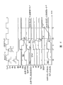
图6是说明本发明的实施例的数据读出工作的工作波形图。Fig. 6 is an operation waveform diagram illustrating the data readout operation of the embodiment of the present invention.
参照图6,本发明的实施例的一次数据读出工作例如能与时钟信号CLK同步地进行。Referring to FIG. 6 , a data readout operation of the embodiment of the present invention can be performed synchronously with the clock signal CLK, for example.
即,在作为时钟信号CLK的激活边的时刻t1,如果取入芯片选择信号CS及读出命令RC,则数据读出工作开始。与此相伴随,选择行的字线WL被激活,同时数据读出电流Is被供给选择列的位线BL。在时刻t1~tr的前半期间(控制信号/RS的高电平期间),不施加偏磁场,选择列的位线、即数据线DIO的电压达到对应于选择存储单元的电阻(存储数据)的电平。这时的数据线电压被传递给读出输入结点N1及N2,在读出输入结点N2上由电压保持电容器130保持。That is, when the chip select signal CS and the read command RC are fetched at time t1 which is the activation edge of the clock signal CLK, the data read operation starts. Along with this, the word line WL of the selected row is activated, and at the same time, the data read current Is is supplied to the bit line BL of the selected column. During the first half of the time t1~tr (the high level period of the control signal /RS), no bias magnetic field is applied, and the voltage of the bit line of the selected column, that is, the voltage of the data line DIO reaches the value corresponding to the resistance (storage data) of the selected memory cell. level. The data line voltage at this time is transmitted to the sense input nodes N1 and N2, and is held by the
在时刻tr以后的后半期间(控制信号/RS的低电平期间),在选择行的字线WL及控制信号RE呈被激活(高电平)的状态下,与数据写入电流Ip同等的偏流慢慢流过选择行的写入数位线WDL。即,对选择存储单元慢慢地施加偏磁场。与此相对应,选择列的位线(数据线DIO)的电压按照与选择存储单元的存储数据对应的极性而变化(上升或下降)。另外,在后面的实施例2中将详细说明供给生成偏磁场用的偏流的结构。In the second half period after the time tr (low level period of the control signal /RS), when the word line WL and the control signal RE of the selected row are activated (high level), the data writing current Ip is equal to The bias current slowly flows through the write digit line WDL of the selected row. That is, a bias magnetic field is gradually applied to the selected memory cell. Correspondingly, the voltage of the bit line (data line DIO) of the selected column changes (rises or falls) in accordance with the polarity corresponding to the stored data of the selected memory cell. In addition, the configuration for supplying a bias current for generating a bias magnetic field will be described in detail in
由偏磁场产生的数据线电压的变化由耦合电容器110传递给读出输入结点N1,所以在读出输入结点N1及N2之间发生对应于选择存储单元的极性的电压差。通过用读出放大器120、146及锁存电路148,放大该电压差,能生成读出数据RDT。Changes in the data line voltage due to the bias magnetic field are transmitted to the sense input node N1 by the
另外,由相当于下一个时钟激活边的时刻t2开始,从数据输出端子4a输出对应于读出数据RDT的输出数据DOUT。由于由流过写入数位线WDL的偏流(数据写入电流Ip)加在选择存储单元上的偏磁场的作用,隧道磁阻元件TMR的磁化方向不反转。因此,在使偏磁场消失的时刻,选择存储单元的磁化方向返回与数据读出工作前相同的状态。这样,本发明的实施例的数据读出方法是非破坏读出方法,所以不需要进行现有的自基准读出的数据再写入工作。Also, from time t2 corresponding to the next clock activation edge, output data DOUT corresponding to read data RDT is output from
另外,将进行1位的数据读出及数据写入用的结构作为一个块,能由多个块构成MRAM装置。图6中一并示出了这样构成的数据读出工作。In addition, an MRAM device can be constituted by a plurality of blocks by taking the structure for performing data reading and writing of 1 bit as one block. FIG. 6 also shows the data reading operation configured in this way.
在有多个块的MRAM装置中,在各块中并行地进行同样的数据读出工作,在时刻t2,在各块中生成来自选择存储单元的读出数据RDT。在这样的结构中,在时刻t2以后的各时钟激活边时刻,能输出分别来自多个块的读出数据RDT,作为脉冲串式的输出数据DOUT。在图6中示出了以下工作例:在时刻t2,对应于来自一个块的读出数据RDT,作为输出数据DOUT输出“0”,从作为下一个时钟激活边的时刻t3开始,对应于另一个块的读出数据RDT,作为输出数据DOUT输出“1”。In an MRAM device having a plurality of blocks, the same data read operation is performed in parallel in each block, and at time t2, read data RDT from a selected memory cell is generated in each block. In such a configuration, read data RDT from a plurality of blocks can be output as burst output data DOUT at each clock activation time after time t2. In Fig. 6, the following operation example is shown: At time t2, corresponding to the read data RDT from one block, "0" is output as output data DOUT, and from time t3 as the next clock activation edge, corresponding to another The read data RDT of one block outputs "1" as the output data DOUT.
这样,在本发明的实施例的结构中,也能不使用基准单元,而通过只对选择存储单元的存取,进行自基准方式的数据读出。即,根据通过包括同一存储单元、同一位线、同一数据线及同一读出放大器等的同一数据读出路径进行的电压比较,生成读出数据。由于不需要基准单元,所以对各MTJ存储单元进行数据存储,能将全部MTJ存储单元作为有效位使用。In this way, in the structure of the embodiment of the present invention, it is also possible to read data from the reference method by accessing only the selected memory cells without using the reference cell. That is, read data is generated based on voltage comparisons performed through the same data read path including the same memory cell, the same bit line, the same data line, and the same sense amplifier. Since no reference cell is required, data is stored in each MTJ memory cell, and all MTJ memory cells can be used as valid bits.
通过进行自基准方式的数据读出,避免构成数据读出路径的各电路的制造离散引起的偏移等的影响,能使数据读出工作高精度化。即,根据与基准单元等其他存储单元或与其相伴随的数据读出电路系统的比较,来自从选择存储单元进行数据读出,更能排除制造离散等的影响,能进行高精度的数据读出。By performing data reading in the self-reference method, the influence of offset or the like caused by manufacturing variations of each circuit constituting the data reading path can be avoided, and the data reading operation can be highly accurate. That is, based on the comparison with other memory cells such as the reference cell or the data readout circuit system accompanying it, the data is read from the selected memory cell, and the influence of manufacturing variance can be eliminated, and high-precision data readout can be performed. .
另外,在本实施例的结构中,在一次数据读出工作内,由于不需要现有的自基准读出那样的强制的数据写入及数据读出、以及伴随选择存储单元的存储数据破坏的再写入,所以能高速地进行自基准读出。In addition, in the structure of this embodiment, in one data read operation, since there is no need for forced data writing and data reading as in the existing self-reference reading, and the destruction of stored data accompanying selected memory cells is unnecessary. Since rewriting is performed, high-speed self-reference reading can be performed.
特别是仍然维持字线WL的激活状态而开始施加偏磁场,通过在规定的时刻取出由该偏磁场的作用生产的数据线DIO的连续的电压变化,进行数据读出,所以更能使数据读出高速化。In particular, the activation state of the word line WL is still maintained and the bias magnetic field is applied, and the continuous voltage change of the data line DIO produced by the action of the bias magnetic field is taken out at a predetermined time to perform data readout, so the data readout can be further performed. out of high speed.
另外,由于通过偏磁场施加前的读出放大器120的负反馈工作,能调整读出放大器120的偏移,所以更能使数据读出高精度化。In addition, since the offset of the
另外,通过将数据写入时用的流过写入数位线WDL的电流作为发生偏磁场用的偏流,不需要新配置数据读出时供给偏流用的电路,所以能简化电路结构。Also, by using the current flowing through write digit line WDL for data writing as a bias current for generating a bias field, it is not necessary to newly arrange a circuit for supplying bias current for data reading, so that the circuit configuration can be simplified.
实施例1的变形例Modification of
在实施例1的变形例中,说明数据读出电路的另一结构例。In a modified example of the first embodiment, another configuration example of the data readout circuit will be described.
参照图7,在实施例1的变形例的数据读出电路的结构中,与图5所示的实施例1的结构相比较,不同的地方在于备有预充电晶体管149,来代替晶体管开关145。除了图7中记载的读出放大器120的外围电路部分以外,数据读出电路的结构、以及其他电路结构与实施例1相同,所以详细说明不再重复。Referring to FIG. 7, in the structure of the data readout circuit of the modified example of
预充电晶体管149由N沟道MOS晶体管构成,连接在预充电电压Vpc#和读出输入结点N1之间。预充电晶体管149与反馈开关140一样,响应控制信号/RS而通·断。The
由于这样构成,所以在数据读出工作前及数据读出工作时的偏磁场施加前,读出输入结点N1被充电到预充电电压Vpc#。其结果,读出输入结点N2被设定为与预充电电压Vpc#相同的电平。With this configuration, the read input node N1 is charged to the precharge voltage Vpc# before the data read operation and before the application of the bias magnetic field during the data read operation. As a result, sense input node N2 is set to the same level as precharge voltage Vpc#.
另一方面,与实施例1相同,数据线DIO在数据读出工作前由电流供给晶体管105充电到预充电电压Vpc,在数据读出工作时,随着对应于选择存储单元的电阻(存储数据)的电压电平的变化而变化。On the other hand, the same as in
从该状态开始,在偏磁场施加后,反馈开关140及预充电晶体管149导通,与实施例1同样地施加偏磁场。与此相对应,读出输入结点N1的电压随着偏磁场施加后的数据线DIO的电压变化,从预充电电压Vpc#开始变化。另一方面,读出输入结点N2保持着预充电电压Vpc#,所以作为读出放大器120的输出结点的结点N3的电压与实施例1同样地变化。其结果,能进行与实施例1同样地数据读出。From this state, after the bias magnetic field is applied, the
这样,在实施例1的变形例的结构中,使数据线DIO的预充电电压Vpc、以及偏磁场施加前的平衡状态下的读出输入结点N1、N2的预充电电压Vpc#独立,能分别进行最佳设定。In this way, in the configuration of the modified example of the first embodiment, the precharge voltage Vpc of the data line DIO and the precharge voltage Vpc# of the sense input nodes N1 and N2 in the equilibrium state before bias magnetic field application are made independent, so that Make the best settings for each.
例如,考虑MTJ存储单元的MR(Magneto-Resistive)特性,将数据线DIO的预充电电压Vpc设定为容易实现耦合电阻差ΔR(Rmax-Rmin)的电平,另一方面,能与其独立地将读出输入结点N1及N2的预充电电压Vpc#设定为适合于确保读出放大器120的工作容限的电平。这能通过利用耦合电容器110,使数据线DIO和读出放大器120的读出输入结点N1绝缘来实现。因此,能任意地选择数据线DIO及读出输入结点N1的预充电电压。For example, considering the MR (Magneto-Resistive) characteristics of the MTJ memory cell, the precharge voltage Vpc of the data line DIO is set to a level at which the coupling resistance difference ΔR (Rmax-Rmin) can be easily realized. The precharge voltage Vpc# of the sense input nodes N1 and N2 is set to a level suitable for securing the operating margin of the
利用这样的结构,与实施例1相比较,更能提高数据读出工作容限。With such a structure, compared with the first embodiment, the data reading operation margin can be further improved.
实施例2Example 2
在实施例2中,说明将电流供给数据写入电流(数据写入时)及偏流(数据读出时)兼用的写入数位线WDL用的结构。In
图8是表示控制对写入数位线WDL的电流供给的电路组的实施例2的结构的电路图。FIG. 8 is a circuit diagram showing a configuration of a second embodiment of a circuit group for controlling current supply to write digit line WDL.
参照图8,分别对应于写入数位线WDL设置的写入数位线驱动器85有作为N沟道MOS晶体管的驱动晶体管86,该驱动晶体管86与对应的写入数位线WDL串联连接在传递电源电压Vcc1的电源电压布线VPL和接地电压布线GPL之间。接地电压布线GPL通过晶体管开关88,与固定电压Vss连接。晶体管开关88响应控制信号而进行通·断。在除了MRAM装置的备用模式时及低功耗模式时以外的激活期间内,控制信号ACT被激活成高电平。在控制信号ACT的非激活期间内,接地电压布线GPL呈浮动状态,通过使N沟道MOS晶体管的源极电压上升,栅·源之间的电压呈负压,能降低该晶体管的泄漏电流。Referring to FIG. 8 , the write
另外,分别对应于写入数位线驱动器85(驱动晶体管86)、即对应于各存储单元行,配置写入数位线驱动控制单元150。In addition, the write digit line
各写入数位线驱动控制单元150在数据读出时及数据写入时都根据对应的存储单元行的行选择结果,使对应的驱动晶体管86导通。对应的驱动晶体管86使电流在被导通的写入数位线WDL中从电源电压布线VPL朝向接地电压布线GPL的方向流。这样,数据写入时为了使充分的数据写入电流流过,用比包括数据读出电路系统的其他外围电路的电源电压Vcc2高的电源电压Vcc1,驱动被激活的写入数位线WDL。Each write digit line
写入数位线驱动控制单元150包括逻辑电路155、电平变换电路160、电流供给晶体管165、以及倒相器170。图8作为一例,具有代表性地表示第J行(J:自然数)的写入数位线驱动控制单元150的结构。The write digit line
逻辑电路155有输出控制信号WE及RS的OR逻辑运算结果的逻辑门156、以及将行译码信号Rd(j)和逻辑门156的输出信号的AND逻辑运算结果输出给结点N10的逻辑门157。控制信号WE及RS与数据读出系统电路(读出放大器120等)的信号相同,有从固定电压Vss(低电平)到电源电压Vcc2(高电平)的振幅。即,在选择了对应的存储单元行的情况下,行译码信号Rd(j)被激活成高电平(电源电压Vcc2)。The
数据写入时(控制信号WE=高电平)及数据读出时的偏压施加时(控制信号RS=高电平)各情况下,在选择了对应的存储单元行时,结点N10的电压由逻辑电路155设定为高电平(电源电压Vcc2),在除此以外的情况下,设定为低电平(固定电压Vss)。When data is written (control signal WE=high level) and when data is read (control signal RS=high level) in each case, when the corresponding memory cell row is selected, the node N10 The voltage is set to a high level (power supply voltage Vcc2 ) by the
倒相器170有在电源电压Vcc2及固定电压Vss之间构成CMOS倒相器那样连接的P沟道MOS晶体管172及N沟道MOS晶体管174。晶体管172及174的各栅极与结点N10连接,晶体管172及174的连接栅极连接在结点N12上。The
电平变换电路160有分别连接在结点N11和结点Ng及/Ng之间的P沟道MOS晶体管161及162;以及分别连接在结点Ng及/Ng和固定电压Vss之间的N沟道MOS晶体管163及164。晶体管161的栅极与结点/Ng连接,晶体管162的栅极与结点Ng连接。晶体管163的栅极与相当于倒相器170的输出结点的结点N12连接,晶体管164的栅极与结点N10连接。The
电平变换电路160在结点N10被设定为高电平(电源电压Vcc2)时,将输出结点Ng设定为高电平(电源电压Vcc1),在结点N10被设定为低电平(固定电压Vss)时,将输出结点Ng设定为低电平(固定电压Vss)。结点Ng与对应的驱动晶体管86的栅极连接。结点/Ng的电压被设定为与结点Ng反相的电压。The
这样,电平变换电路160根据对应的存储单元行的行选择结果,使逻辑电路155的输出信号的振幅增大,传递给驱动晶体管86的栅极。In this way, the
电流供给晶体管165连接在电源电压Vcc1和结点N11之间,由在其栅极接收控制信号RS的P沟道MOS晶体管构成。因此,电流供给晶体管165根据控制信号RS的电平,控制电平变换电路160的工作电流。The
具体地说,在控制信号RS呈低电平的期间,电流供给晶体管165完全导通,供给工作电流,所以电平变换电路160能高速工作。与此不同,在控制信号RS呈高电平的期间,由于电流供给晶体管165的栅极电压被设定为作为电源电压Vcc1和固定电压Vss的中间电平的Vcc2,所以电流供给晶体管165的通过电流减少。其结果,电平变换电路160的工作电流减少,工作速度降低。Specifically, when the control signal RS is at a low level, the
因此,数据写入工作时,利用全额供给工作电流的电平变换电路160,选择行的驱动晶体管86的栅极电压迅速地变化到高电平(电源电压Vcc1)。其结果,写入数位线WDL与电源电压Vcc1耦合,迅速地开始供给数据写入电流。Therefore, during the data writing operation, the gate voltage of the
与此不同,数据读出工作的偏磁场施加时,由于电平变换电路160的工作电流减少,所以选择行的驱动晶体管86的栅极电压缓慢地变化到高电平(电源电压Vcc1)。其结果,供给写入数位线WDL的偏流比数据写入时的数据写入电流上升得慢。On the other hand, when a bias magnetic field is applied for the data read operation, the gate voltage of the
因此,加在选择存储单元上的偏磁场也由于变化缓慢,所以能避免数据线DIO的电压急剧变化,能进行降低了噪声的稳定的数据读出。Therefore, since the bias magnetic field applied to the selected memory cell also changes slowly, it is possible to avoid sudden changes in the voltage of the data line DIO and to perform stable data reading with reduced noise.
另外,通过对接地电压布线GPL设置晶体管开关88,能使非选择时的写入数位线WDL呈浮动状态。其结果,在对应于非选择的写入数位线的驱动晶体管86(N沟道MOS晶体管)中,源极电压(写入数位线WDL电压)比栅极电压(固定电压Vss)高。其结果,负偏压加在栅·源之间,所以能减少驱动晶体管86的泄漏电流。In addition, by providing the
其结果,由于导通时的电流驱动力增大,所以即使将驱动晶体管86的阈值电压设定得低,也能防止截止时发生泄漏电流。As a result, since the current driving force at the turn-on time increases, even if the threshold voltage of the
实施例2的变形例1
图9是表示控制对写入数位线WDL的电流供给的电路组的实施例2的变形例1的结构的电路图。9 is a circuit diagram showing the configuration of
参照图9,在实施例2的变形例1的结构中,与图8所示的实施例2的结构相比较,不同的地方在于:写入数位线驱动器85由作为P沟道MOS晶体管的驱动晶体管87构成。不是结点Ng而是结点/Ng连接在驱动晶体管87的栅极上。Referring to FIG. 9, in the structure of
与此相伴随,晶体管开关88与图8所示的结构不同,而是采用P沟道MOS晶体管,连接在电源电压Vcc1及电源电压布线VPL之间。另外,作为控制信号ACT的反转信号的/ACT被输入晶体管开关88的栅极。Along with this, the
在写入数位线驱动控制单元105中,电流供给晶体管165采用N沟道MOS晶体管,不是设置在电源电压Vcc1及结点N11之间,而是设置在结点N13及固定电压Vss之间。另外,还设有控制电流供给晶体管165的栅极电压用的电流限制控制电路175。In the write digit line
电流限制控制电路175有连接在电源电压Vcc2及结点N14之间的P沟道MOS晶体管176、以及连接在结点N14及固定电压Vss之间的N沟道MOS晶体管178。结点N14与电流供给晶体管(N沟道MOS晶体管)165的栅极连接。由于晶体管176的栅极与固定电压Vss连接。所以晶体管176经常呈导通状态。与此不同,控制信号RS被输入晶体管178的栅极。The current
电流限制控制电路175响应控制信号RS,控制结点N14的电压电平。具体地说,在控制信号RS呈高电平期间、即在数据读出时的偏磁场施加期间,结点N14的电压被设定为电源电压Vcc2及固定电压Vss的中间电平。其结果,电流供给晶体管165的通过电流受到限制,电平变换电路160的工作速度下降。即,由电平变换电路160产生的结点Ng及/Ng的电压变化缓慢。The current
与此不同,在控制信号RS呈低电平期间,结点N14由晶体管176设定为电源电压Vcc2。其结果,电流供给晶体管165的通过电流增大,由电平变换电路160产生的结点Ng及/Ng的电压变化迅速。Different from this, when the control signal RS is at a low level, the node N14 is set to the power supply voltage Vcc2 by the
另外,写入数位线驱动控制单元150的其他部分的结构及工作与用图8说明过的相同,详细说明不重复。因此,即使在写入数位线WDL的驱动开关中采用了P沟道MOS晶体管的情况下,也能获得与实施例2同样的效果。In addition, the configuration and operation of other parts of the write digit line
实施例2的变形例2
图10是表示控制对写入数位线WDL的电流供给的电路组的实施例2的变形例2的结构的电路图。FIG. 10 is a circuit diagram showing the configuration of
参照图10,在实施例2的变形例2的结构中,与图8所示的实施例2的结构相比较,不同的地方在于:作为N沟道MOS晶体管的驱动晶体管86连接在对应的写入数位线WDL和固定电压Vss之间。另外,能省略备用时使写入数位线WDL呈浮动状态用的晶体管开关88的配置。Referring to FIG. 10, in the structure of
包括写入数位线驱动控制单元150的其他部分的结构及工作与用图8说明过的相同,详细说明不重复。即使这样构成,也能获得与实施例2同样的效果。The structure and operation of other parts including the write-in digit line
另外,在具有同一晶体管尺寸的P沟道型MOS晶体管及N沟道MOS晶体管中,由于后者的电流驱动能力大,所以通过将N沟道型MOS晶体管用于驱动晶体管、以及配置晶体管开关88,在图8所示的结构中,特别能谋求写入数位线驱动器85的小型化。In addition, in the P-channel type MOS transistor and the N-channel MOS transistor having the same transistor size, since the latter has a large current driving capability, by using the N-channel type MOS transistor as the driving transistor and disposing the
Claims (14)
Applications Claiming Priority (3)
| Application Number | Priority Date | Filing Date | Title |
|---|---|---|---|
| JP181364/02 | 2002-06-21 | ||
| JP2002181364A JP4208498B2 (en) | 2002-06-21 | 2002-06-21 | Thin film magnetic memory device |
| JP181364/2002 | 2002-06-21 |
Publications (2)
| Publication Number | Publication Date |
|---|---|
| CN1467741A CN1467741A (en) | 2004-01-14 |
| CN100440373C true CN100440373C (en) | 2008-12-03 |
Family
ID=29728283
Family Applications (1)
| Application Number | Title | Priority Date | Filing Date |
|---|---|---|---|
| CNB031066313A Expired - Fee Related CN100440373C (en) | 2002-06-21 | 2003-02-27 | Thin-film magnetic storage device capable of reading data in a self-reference manner |
Country Status (6)
| Country | Link |
|---|---|
| US (3) | US6856565B2 (en) |
| JP (1) | JP4208498B2 (en) |
| KR (1) | KR100522629B1 (en) |
| CN (1) | CN100440373C (en) |
| DE (1) | DE10307991A1 (en) |
| TW (1) | TW580700B (en) |
Families Citing this family (24)
| Publication number | Priority date | Publication date | Assignee | Title |
|---|---|---|---|---|
| JP4131923B2 (en) * | 2002-09-25 | 2008-08-13 | 株式会社東芝 | Magnetic random access memory |
| KR100560661B1 (en) * | 2003-06-19 | 2006-03-16 | 삼성전자주식회사 | How to read magnetic memory |
| US7027319B2 (en) * | 2003-06-19 | 2006-04-11 | Hewlett-Packard Development Company, L.P. | Retrieving data stored in a magnetic integrated memory |
| JP4287235B2 (en) * | 2003-10-09 | 2009-07-01 | 株式会社東芝 | Nonvolatile semiconductor memory device |
| US6972989B2 (en) * | 2003-10-10 | 2005-12-06 | Infincon Technologies Ag | Reference current distribution in MRAM devices |
| JP4063239B2 (en) | 2004-04-16 | 2008-03-19 | ソニー株式会社 | Data reading circuit and semiconductor device having this circuit |
| US7697321B2 (en) * | 2006-05-22 | 2010-04-13 | Everspin Technologies, Inc. | Non-volatile memory cell and methods thereof |
| CN101689858B (en) * | 2007-06-25 | 2012-08-22 | 太阳诱电株式会社 | Semiconductor device |
| US7706176B2 (en) * | 2008-01-07 | 2010-04-27 | Qimonda Ag | Integrated circuit, cell arrangement, method for manufacturing an integrated circuit and for reading a memory cell status, memory module |
| JP2009230798A (en) * | 2008-03-21 | 2009-10-08 | Toshiba Corp | Magnetic storage device |
| US7751231B2 (en) | 2008-05-05 | 2010-07-06 | Qimonda Ag | Method and integrated circuit for determining the state of a resistivity changing memory cell |
| KR100929826B1 (en) * | 2008-06-04 | 2009-12-07 | 주식회사 하이닉스반도체 | A semiconductor memory device |
| KR101057724B1 (en) * | 2009-05-13 | 2011-08-18 | 주식회사 하이닉스반도체 | Semiconductor memory device and driving method thereof |
| EP2276034B1 (en) * | 2009-07-13 | 2016-04-27 | Crocus Technology S.A. | Self-referenced magnetic random access memory cell |
| US8228715B2 (en) | 2010-05-28 | 2012-07-24 | Everspin Technologies, Inc. | Structures and methods for a field-reset spin-torque MRAM |
| JP5715306B2 (en) * | 2011-08-29 | 2015-05-07 | インテル・コーポレーション | Snapback detection at tile level using coupling capacitors in crosspoint arrays |
| US9183911B2 (en) | 2011-11-17 | 2015-11-10 | Everspin Technologies, Inc. | Hybrid read scheme for spin torque MRAM |
| US8493776B1 (en) * | 2012-02-02 | 2013-07-23 | Taiwan Semiconductor Manufacturing Co., Ltd. | MRAM with current-based self-referenced read operations |
| US8923041B2 (en) | 2012-04-11 | 2014-12-30 | Everspin Technologies, Inc. | Self-referenced sense amplifier for spin torque MRAM |
| US9147454B2 (en) * | 2013-01-14 | 2015-09-29 | Qualcomm Incorporated | Magnetic tunneling junction non-volatile register with feedback for robust read and write operations |
| US10032509B2 (en) * | 2015-03-30 | 2018-07-24 | Toshiba Memory Corporation | Semiconductor memory device including variable resistance element |
| JP2019057348A (en) * | 2017-09-21 | 2019-04-11 | 東芝メモリ株式会社 | Memory device |
| JP2019164848A (en) * | 2018-03-19 | 2019-09-26 | 東芝メモリ株式会社 | Magnetic storage device |
| JP2024046318A (en) * | 2022-09-22 | 2024-04-03 | 株式会社東芝 | Sense amplifier circuit and semiconductor memory device |
Citations (2)
| Publication number | Priority date | Publication date | Assignee | Title |
|---|---|---|---|---|
| US6055178A (en) * | 1998-12-18 | 2000-04-25 | Motorola, Inc. | Magnetic random access memory with a reference memory array |
| US6185143B1 (en) * | 2000-02-04 | 2001-02-06 | Hewlett-Packard Company | Magnetic random access memory (MRAM) device including differential sense amplifiers |
Family Cites Families (9)
| Publication number | Priority date | Publication date | Assignee | Title |
|---|---|---|---|---|
| JP3425891B2 (en) | 1999-04-20 | 2003-07-14 | Necエレクトロニクス株式会社 | Semiconductor memory device and method of reading data stored in memory cell |
| DE19947118C1 (en) | 1999-09-30 | 2001-03-15 | Infineon Technologies Ag | Method and circuit arrangement for evaluating the information content of a memory cell |
| US6317376B1 (en) | 2000-06-20 | 2001-11-13 | Hewlett-Packard Company | Reference signal generation for magnetic random access memory devices |
| DE10036140C1 (en) | 2000-07-25 | 2001-12-20 | Infineon Technologies Ag | Non-destructive read-out of MRAM memory cells involves normalizing actual cell resistance, comparing normalized and normal resistance values, detecting content from the result |
| JP4726290B2 (en) | 2000-10-17 | 2011-07-20 | ルネサスエレクトロニクス株式会社 | Semiconductor integrated circuit |
| DE10059182C2 (en) | 2000-11-29 | 2002-10-24 | Infineon Technologies Ag | Circuit arrangement for the non-destructive, self-normalizing reading of MRAM memory cells |
| JP4667594B2 (en) * | 2000-12-25 | 2011-04-13 | ルネサスエレクトロニクス株式会社 | Thin film magnetic memory device |
| JP4052829B2 (en) * | 2001-12-12 | 2008-02-27 | 株式会社ルネサステクノロジ | Thin film magnetic memory device |
| JP4084084B2 (en) | 2002-05-23 | 2008-04-30 | 株式会社ルネサステクノロジ | Thin film magnetic memory device |
-
2002
- 2002-06-21 JP JP2002181364A patent/JP4208498B2/en not_active Expired - Fee Related
- 2002-11-14 TW TW091133349A patent/TW580700B/en not_active IP Right Cessation
- 2002-12-20 US US10/323,916 patent/US6856565B2/en not_active Expired - Fee Related
-
2003
- 2003-02-25 DE DE10307991A patent/DE10307991A1/en not_active Withdrawn
- 2003-02-27 KR KR10-2003-0012303A patent/KR100522629B1/en not_active Expired - Fee Related
- 2003-02-27 CN CNB031066313A patent/CN100440373C/en not_active Expired - Fee Related
-
2005
- 2005-01-31 US US11/045,100 patent/US7057925B2/en not_active Expired - Fee Related
-
2006
- 2006-03-14 US US11/374,063 patent/US7313017B2/en not_active Expired - Fee Related
Patent Citations (2)
| Publication number | Priority date | Publication date | Assignee | Title |
|---|---|---|---|---|
| US6055178A (en) * | 1998-12-18 | 2000-04-25 | Motorola, Inc. | Magnetic random access memory with a reference memory array |
| US6185143B1 (en) * | 2000-02-04 | 2001-02-06 | Hewlett-Packard Company | Magnetic random access memory (MRAM) device including differential sense amplifiers |
Also Published As
| Publication number | Publication date |
|---|---|
| US7057925B2 (en) | 2006-06-06 |
| US20050128800A1 (en) | 2005-06-16 |
| KR100522629B1 (en) | 2005-10-20 |
| US20030235069A1 (en) | 2003-12-25 |
| KR20030097641A (en) | 2003-12-31 |
| US6856565B2 (en) | 2005-02-15 |
| TW580700B (en) | 2004-03-21 |
| US7313017B2 (en) | 2007-12-25 |
| US20060152972A1 (en) | 2006-07-13 |
| JP2004030714A (en) | 2004-01-29 |
| CN1467741A (en) | 2004-01-14 |
| JP4208498B2 (en) | 2009-01-14 |
| TW200400508A (en) | 2004-01-01 |
| DE10307991A1 (en) | 2004-03-04 |
Similar Documents
| Publication | Publication Date | Title |
|---|---|---|
| CN100440373C (en) | Thin-film magnetic storage device capable of reading data in a self-reference manner | |
| US6842366B2 (en) | Thin film magnetic memory device executing self-reference type data read | |
| JP4046513B2 (en) | Semiconductor integrated circuit | |
| US7233537B2 (en) | Thin film magnetic memory device provided with a dummy cell for data read reference | |
| US6903963B2 (en) | Thin-film magnetic memory device executing data writing with data write magnetic fields in two directions | |
| US6597601B2 (en) | Thin film magnetic memory device conducting data read operation without using a reference cell | |
| CN1329918C (en) | Thin film magnetic memory of shortened data reading data line charging time | |
| US7085174B2 (en) | Semiconductor memory device with current driver providing bi-directional current to data write line | |
| CN100505085C (en) | Thin-film magnetic storage device in which a plurality of memory cells share access elements | |
| US6791875B2 (en) | Thin film magnetic memory device realizing both high-speed data reading operation and stable operation | |
| CN100361230C (en) | Thin film magnetic memory device with memory cell having magnetic tunnel junction | |
| JP2008084533A (en) | Thin magnetic film storage device | |
| JP4749454B2 (en) | Thin film magnetic memory device |
Legal Events
| Date | Code | Title | Description |
|---|---|---|---|
| C06 | Publication | ||
| PB01 | Publication | ||
| C10 | Entry into substantive examination | ||
| SE01 | Entry into force of request for substantive examination | ||
| C14 | Grant of patent or utility model | ||
| GR01 | Patent grant | ||
| C17 | Cessation of patent right | ||
| CF01 | Termination of patent right due to non-payment of annual fee |
Granted publication date: 20081203 Termination date: 20140227 |