CN100439758C - Timing belt tensioner with stops controlled by frictional brake - Google Patents
Timing belt tensioner with stops controlled by frictional brake Download PDFInfo
- Publication number
- CN100439758C CN100439758C CNB028244214A CN02824421A CN100439758C CN 100439758 C CN100439758 C CN 100439758C CN B028244214 A CNB028244214 A CN B028244214A CN 02824421 A CN02824421 A CN 02824421A CN 100439758 C CN100439758 C CN 100439758C
- Authority
- CN
- China
- Prior art keywords
- pivot arm
- pivot
- belt
- clutch spring
- tension
- Prior art date
- Legal status (The legal status is an assumption and is not a legal conclusion. Google has not performed a legal analysis and makes no representation as to the accuracy of the status listed.)
- Expired - Lifetime
Links
Images


Classifications
-
- F—MECHANICAL ENGINEERING; LIGHTING; HEATING; WEAPONS; BLASTING
- F16—ENGINEERING ELEMENTS AND UNITS; GENERAL MEASURES FOR PRODUCING AND MAINTAINING EFFECTIVE FUNCTIONING OF MACHINES OR INSTALLATIONS; THERMAL INSULATION IN GENERAL
- F16H—GEARING
- F16H7/00—Gearings for conveying rotary motion by endless flexible members
- F16H7/08—Means for varying tension of belts, ropes, or chains
- F16H7/10—Means for varying tension of belts, ropes, or chains by adjusting the axis of a pulley
- F16H7/12—Means for varying tension of belts, ropes, or chains by adjusting the axis of a pulley of an idle pulley
- F16H7/1254—Means for varying tension of belts, ropes, or chains by adjusting the axis of a pulley of an idle pulley without vibration damping means
- F16H7/1281—Means for varying tension of belts, ropes, or chains by adjusting the axis of a pulley of an idle pulley without vibration damping means where the axis of the pulley moves along a substantially circular path
- F16H7/129—Means for varying tension of belts, ropes, or chains by adjusting the axis of a pulley of an idle pulley without vibration damping means where the axis of the pulley moves along a substantially circular path with means for impeding reverse motion
-
- F—MECHANICAL ENGINEERING; LIGHTING; HEATING; WEAPONS; BLASTING
- F16—ENGINEERING ELEMENTS AND UNITS; GENERAL MEASURES FOR PRODUCING AND MAINTAINING EFFECTIVE FUNCTIONING OF MACHINES OR INSTALLATIONS; THERMAL INSULATION IN GENERAL
- F16D—COUPLINGS FOR TRANSMITTING ROTATION; CLUTCHES; BRAKES
- F16D41/00—Freewheels or freewheel clutches
- F16D41/20—Freewheels or freewheel clutches with expandable or contractable clamping ring or band
- F16D41/206—Freewheels or freewheel clutches with expandable or contractable clamping ring or band having axially adjacent coils, e.g. helical wrap-springs
-
- F—MECHANICAL ENGINEERING; LIGHTING; HEATING; WEAPONS; BLASTING
- F16—ENGINEERING ELEMENTS AND UNITS; GENERAL MEASURES FOR PRODUCING AND MAINTAINING EFFECTIVE FUNCTIONING OF MACHINES OR INSTALLATIONS; THERMAL INSULATION IN GENERAL
- F16H—GEARING
- F16H7/00—Gearings for conveying rotary motion by endless flexible members
- F16H7/08—Means for varying tension of belts, ropes, or chains
- F16H7/10—Means for varying tension of belts, ropes, or chains by adjusting the axis of a pulley
- F16H7/12—Means for varying tension of belts, ropes, or chains by adjusting the axis of a pulley of an idle pulley
- F16H7/1209—Means for varying tension of belts, ropes, or chains by adjusting the axis of a pulley of an idle pulley with vibration damping means
- F16H7/1218—Means for varying tension of belts, ropes, or chains by adjusting the axis of a pulley of an idle pulley with vibration damping means of the dry friction type
-
- F—MECHANICAL ENGINEERING; LIGHTING; HEATING; WEAPONS; BLASTING
- F16—ENGINEERING ELEMENTS AND UNITS; GENERAL MEASURES FOR PRODUCING AND MAINTAINING EFFECTIVE FUNCTIONING OF MACHINES OR INSTALLATIONS; THERMAL INSULATION IN GENERAL
- F16H—GEARING
- F16H7/00—Gearings for conveying rotary motion by endless flexible members
- F16H7/08—Means for varying tension of belts, ropes, or chains
- F16H2007/0802—Actuators for final output members
- F16H2007/081—Torsion springs
-
- F—MECHANICAL ENGINEERING; LIGHTING; HEATING; WEAPONS; BLASTING
- F16—ENGINEERING ELEMENTS AND UNITS; GENERAL MEASURES FOR PRODUCING AND MAINTAINING EFFECTIVE FUNCTIONING OF MACHINES OR INSTALLATIONS; THERMAL INSULATION IN GENERAL
- F16H—GEARING
- F16H7/00—Gearings for conveying rotary motion by endless flexible members
- F16H7/08—Means for varying tension of belts, ropes, or chains
- F16H7/0829—Means for varying tension of belts, ropes, or chains with vibration damping means
- F16H2007/084—Means for varying tension of belts, ropes, or chains with vibration damping means having vibration damping characteristics dependent on the moving direction of the tensioner
-
- F—MECHANICAL ENGINEERING; LIGHTING; HEATING; WEAPONS; BLASTING
- F16—ENGINEERING ELEMENTS AND UNITS; GENERAL MEASURES FOR PRODUCING AND MAINTAINING EFFECTIVE FUNCTIONING OF MACHINES OR INSTALLATIONS; THERMAL INSULATION IN GENERAL
- F16H—GEARING
- F16H7/00—Gearings for conveying rotary motion by endless flexible members
- F16H7/08—Means for varying tension of belts, ropes, or chains
- F16H7/0829—Means for varying tension of belts, ropes, or chains with vibration damping means
- F16H7/0831—Means for varying tension of belts, ropes, or chains with vibration damping means of the dry friction type
-
- F—MECHANICAL ENGINEERING; LIGHTING; HEATING; WEAPONS; BLASTING
- F16—ENGINEERING ELEMENTS AND UNITS; GENERAL MEASURES FOR PRODUCING AND MAINTAINING EFFECTIVE FUNCTIONING OF MACHINES OR INSTALLATIONS; THERMAL INSULATION IN GENERAL
- F16H—GEARING
- F16H7/00—Gearings for conveying rotary motion by endless flexible members
- F16H7/08—Means for varying tension of belts, ropes, or chains
- F16H7/0829—Means for varying tension of belts, ropes, or chains with vibration damping means
- F16H7/0834—Means for varying tension of belts, ropes, or chains with vibration damping means of the viscous friction type, e.g. viscous fluid
Landscapes
- Engineering & Computer Science (AREA)
- General Engineering & Computer Science (AREA)
- Mechanical Engineering (AREA)
- Devices For Conveying Motion By Means Of Endless Flexible Members (AREA)
Abstract
A tensioner ( 10 ) features a backstop device ( 40 ) which allows free rotation of the pivot arm ( 20 ) in one direction but not the other. Reverse rotation is prevented by friction that is able to resist torque on the pivot arm ( 20 ) under ordinary operating conditions which otherwise could permit belt tooth-skip to occur. In disclosed embodiments, the backstop device ( 40 ) includes a stop sleeve ( 50 ) and a clamp holder ( 60 ) which are axially interlocked and are able to rotate relative to each other. A clutch spring ( 80 ) surrounds permits relative rotation between the stop sleeve ( 50 ) and the clamp holder ( 60 ) in one direction but not the other. A clamp ( 70 ) retained within the clamp holder ( 60 ) frictionally engages the pivot shaft. A viscous coupling may be used in place of the frictional clamp.
Description
Invention field
Present invention relates in general to a kind of belt stretcher of automobile, relate in particular to a kind of Timing Belt tension device, wherein the position of stop device is controlled by an overrunning clutch and a friction stopping device behind the arm.
Background technique
In the present technique field, belt tensioner for motor vehicle is known and be used to regulate the tension force of various belt systems, such as Timing Belt.Usually, a belt stretcher comprises a movable supporting structure, and this supporting structure is the part of belt in supporting engine or other mechanical systems rotatably.The rotational position of the arm of a belt stretcher/pulley sub-assembly is adjusted usually automatically, with to because engine thermal expands or shrink and/or belt abrasion and increasing or shortening of the belt path length that causes and stretching compensates, regulate belt tension by this.In addition, whole tension device assembly usually can manpower with respect to the engine body adjustment need not consider the manufacturing tolerances of motor so that tension device is adjustable to the appropriate location on the motor.
The ordinary straps tension device of a common type comprises a fixed structure and a rotational structure, and it is installed in described fixing structural arm/belt pulley sub-assembly pivotally by one usually and is formed.A helical spring is around described rotary member, and the end of spring is connected respectively on described fixed structure and the rotational structure, with the described rotational structure of position bias voltage to the belt tension of maximum.Described rotational structure from the position of the belt tension of minimum when move the position of the belt tension of maximum, described spring bias successively decreases.Though spring force changes, on belt, keeping the tension force of substantial constant in the range of movement that is provided.U. S. Patent 4,473,362 disclose a kind of this type of tension device.
In addition, Timing Belt and chain stretching device have stroke limiting stop usually.A stroke limiting stop generally comprises a pair of fixing stop block, prevents that the pivot arm from exceeding predefined distance from the rotation of normal position; One first backstop restriction pivot arm rotates to belt, and generally is called " free arm stop block ", and one second backstop restriction pivot arm rotates away from belt, generally is called " back stop block ".Described back stop block is normally placed, even so that the pivot arm resists its rotation, does not also have enough laxly with on the tooth that is raised to any one sprocket wheel in the driving in belt, and " skips " or breaks away from from tooth.In other words, back stop block is designed for avoids jumping tooth, otherwise jumping tooth can cause synchronization error between each sprocket wheel, and then causes equipment error and infringement.
For not providing initial manpower that the tension device of adjusting is installed, and the rotation of its rotational structure is intended to compensate the manufacturing tolerances of motor, and it is infeasible being placed on back stop block apart from the common way of a distance, standard pivot arm position.In other words, by the configuration of this kind tension device, tensioner arm is without any fixing normal place, and therefore unfixing back stop block position, therefore perhaps, make between initial tension device installation period, must be manually or preferably adjust stop block position, back automatically.In addition, the mean lifetime of the modern engine components of increase causes longer belt life and belt stretch, and therefore common the requirement is the bigger adjustment range of rotational structure preparation of tension device in the Life cycle of tension device.Therefore, if avoid the manpower adjustment, the automatic adjustment of back stop block position becomes more important.
Some known tensioner design provide the automatic adjustment of stop block behind this kind tension device.For instance, U. S. Patent 4,145,934 disclose a kind of wedge structure, its pusher arm eccentric (bar), in case so that tensioner arm by the tension spring bias voltage when the belt, arm can not rotate away from belt.Similarly, U. S. Patent number 4,351,636 discloses a kind of similar substantially tension device, but has a ratchet-ratchet assembly rather than a wedge structure.At U. S. Patent 4,634, other a kind of ratchet-pawl type tension device mechanism is disclosed in 407.Yet, in each patent, in case tensioner arm when belt rotates, it can not rotate away from belt; Therefore, this kind configuration does not allow during the thermal expansion of engine body belt tension to be controlled.
U. S. Patent 4,583,962 disclose a kind of improved plan in this type of design.Especially, it discloses a kind of arm limited reverse stroke of stop block backward that allows, to adapt to the thermal expansion of motor.The tension device of this patent adopts a kind of spring clutch type non-return device, and disposes a curve bath, rotates backward to permit arm.Similarly, U. S. Patent 4,822,322 and 4,834,694 disclose tension device, and wherein unidirectional mechanism adopts traditional unidirectional (roller) clutch, and the tensioner arm reverse stroke is controlled by curve bath.In addition, U. S. Patent 4,808,148 disclose a kind of tension device, wherein, are not by groove restriction reverse stroke, but between ratchet-ratchet assembly and fixing installation component, a fexible bias pressure element is set (such as, the spring of an elastic material).
All there is following restriction in above-mentioned tensioner design: in case the back stop block moves to the free arm position, perhaps when moving under the condition that be not optimum thermo-motor operation, back stop block can not move backward, leaves belt.Because back stop block is done the time spent in cold start-up and/or engine inversion, shift out most favorable position, tensioner arm will contact the back stop block continually, thereby cause the premature damage of noise, infringement and/or element.In addition, this kind tension device disapproves belt and is reinstalled or change.
U. S. Patent 4,923,435 disclose a kind of tension device that cohesive material is set between described arm and one-way clutch mechanism.Yet, this concrete design can not guarantee nervous belt do not jump tooth.Because if being applied load continuously, belt (do not have motion backward under the situation of driving when automobile, make when motor rotates backward), cohesive material allows the tensioner arm rotation, and cohesive material can not be used as the location link stopper, and can only be as a damping shock absorber.
Summary of the invention
The defective of the present invention by providing a kind of tension device to overcome prior art, wherein, by in its " following " tensioner arm when the free arm position pivots, described backstop is " searching " its proper handling position automatically; It keeps the back stop block position of running under standard or temporary transient (such as vibrations) belt load; Its allow manpower will the back stop block move backward (such as, during installation), and enough make the back stop block mobile backward under the big or prolonged high belt load.
In one embodiment of the invention, a Timing Belt tension device has a pivot that is fixed on the engine body; A pivot arm that is fixed on pivotally on the described pivot; One can be fixed on the torque spring between described pivot arm and the fixed structure (such as, engine body) with turning round, is used at belt tension direction (promptly to a free arm position) the described pivot arm of bias voltage; With one after stop device.Described back stop device comprise the stop sleeve pipe of a general cylindrical shape, friction catch (such as, be roughly clamp holder supporting cylindraceous by one) and overrunning clutch.The preferably collaborative configuration of described stop sleeve pipe and pivot arm is done predetermined, limited amount rotatablely moving to allow described pivot arm with respect to the stop sleeve pipe.Described overrunning clutch allow stop sleeve pipe (and then pivot arm) to the free arm position relative rotate freely motion, but when the stop sleeve pipe rotates away from belt, promptly to minimal belt tension position direction, the stop sleeve pipe is engaged on the friction stopping device, simultaneously friction stopping device described overrunning clutch effectively " grappling " to a fixing anchor point, such as anchoring to pivot or directly anchoring to engine body.Selectively, adopt a hydraulic connector, such as, a kind of connector that uses cohesive material replaces described friction stopping device to implement.
The motion of the minimal belt tension position that described friction stopping device stop arm causes to the belt force close with the power that produces such as crankshaft backward rotation size, but when pivot arm manpower rotates, such as, in installation process, " release " and permission back stop block rotate to the minimal belt tension position.That the configuration of tension device among the present invention has realized installing is easy, simple in structure, and thereby can reduce time and the cost of making and installing.
In the another one scheme of invention, the whirligig that is used for optionally transmitting rotating power or moment of torsion comprise a pair ofly axially directly be interconnected with one another, and can counterrotating rotating member.Overrunning clutch spring one a sheathed relation is arranged on the described a pair of rotating member, and when one in the described rotating member during in the rotation of direction, rotation interlocking (promptly can not relatively rotate), when its in the rotation of opposite direction, allow rotating member to rotate relative to one another.One of rotating member can have the lip of the circle circle expansion of a restriction clutch spring, and clutch spring to have a diameter of one or more circle circles bigger than the diameter of all the other circle circles, rotatably before the interlocking rotating member, to provide a certain amount of free travel at clutch spring.
In one aspect of the invention, provide a kind of belt stretcher that is used for motor vehicle engine, it comprises: a pivot; A pivot arm that is pivoted on the described pivot; A belt pulley that is bearing in rotatably on the described pivot arm; The spring of a described pivot arm of bias voltage on the direction of belt tension; With one after stop device, it comprises an overrunning clutch member and a friction catch member, described friction catch member relatively is installed on the anchor portion by frictional fit, and described anchor portion is fixed with respect to described motor vehicle engine, be placed between described pivot arm and the described friction catch member to described overrunning clutch member running, the structure of described overrunning clutch member and position are set to allow described pivot arm freely to pivot on described belt tension direction, the structure and the position that it is characterized in that described overrunning clutch member are set to stop described pivot arm going up in the opposite direction with respect to described friction catch members pivot with described belt tension side, and wherein said pivot arm can freely rotate with the certain play amount that exists therebetween with respect to described overrunning clutch member.
In another aspect of the present invention, a kind of belt stretcher that is used for motor vehicle engine is provided, it comprises: a pivot; A pivot arm that is pivoted on the described pivot; A belt pulley that is bearing in rotatably on the described pivot arm; The spring of a described pivot arm of bias voltage on the direction of belt tension; With one after stop device, it comprises an arm mate, a friction catch member and an overrunning clutch member, by allowing the slide relative between described overrunning clutch member and the described friction catch member, described back stop device can make described pivot arm freely pivot on described belt tension direction, it is characterized in that by of the engagement of described pivot arm by described arm mate, the friction engagement of a described friction catch member and an anchor site fixing with respect to described motor, and the interlocked of the overrunning clutch member between described friction catch member and the described arm mate is used, described back stop device stops described pivot arm pivoting in the opposite direction with described belt tension side, and comprise a pair of member of axially aligning cylindraceous, it is around described pivot setting and axially be connected to each other each other, one of them of described member cylindraceous and the engagement of described pivot arm, another of described member cylindraceous comprises the clamp holder that supports described friction catch member, and described overrunning clutch member comprises a clutch spring, and described clutch spring is enclosed within on the member of described pair of cylinders shape.
Another aspect of the present invention provides a kind of belt stretcher of automobile, and it comprises: one is installed in the pivot on the motor reliably; One is pivoted on the pivot arm on the described pivot; The belt pulley of one swivel bearing on described pivot arm; One structure and the spring that is set to the described pivot arm of bias voltage on the direction of belt tension; With a back stop device, stop device running ground, described back is arranged between the anchor portion that described pivot arm and fixes with respect to described motor, described back stop device is constructed and is set to allow described pivot arm freely to pivot on described belt tension direction, it is characterized in that described back stop device also constructs and be set to stop described pivot arm pivoting in the opposite direction with described belt tension side, wherein, described pivot arm and described back stop device are equipped with the rotation play for one of between setting preestablishes and size is limited; And described back stop device comprises a pair of stopper element and overrunning clutch member around described pivot setting, wherein said stopper element is interlocked and makes that one of them of described stopper element can be with respect to another rotation of described stopper element, the engagement of described stopper element one of them and described pivot arm, and another of described stopper element is connected with described anchor site, described overrunning clutch member comprises a clutch spring that is enclosed within on the described pair of stopper members, clutch spring allows described stopper element capable of pivoting relative to each other in one direction, and stoping described stopper element capable of pivoting relative to each other on an opposite direction, one of described stopper element has at least one axial slots.
In further aspect of the present invention, a kind of belt stretcher of automobile is provided, it comprises: one is installed in the pivot on the motor reliably; One is pivoted on the pivot arm on the described pivot; The belt pulley of one swivel bearing on described pivot arm; One structure and the spring that is set to the described pivot arm of bias voltage on the direction of belt tension; With a back stop device, stop device running ground, described back is arranged between the anchor portion that described pivot arm and fixes with respect to described motor, described back stop device is constructed and is set to allow described pivot arm freely to pivot on described belt tension direction, described back stop device comprises a pair of stopper element and overrunning clutch member around described pivot setting, the engagement of described stopper element one of them and described pivot arm, and another of described stopper element is connected to described anchor portion, described overrunning clutch member comprises a clutch spring that is enclosed within on the described pair of stopper members, clutch spring allows described stopper element capable of pivoting relative to each other in one direction, it is characterized in that described back stop device is also constructed and is set to utilize prevents that overrunning clutch member that described stopper element rotates in the opposite direction relative to each other from stoping described pivot arm pivoting in the opposite direction with described belt tension side, and described another of wherein said stopper element is connected to described anchor portion by cohesive material.
Description of drawings
Will be for a more detailed description to the present invention with reference to the accompanying drawings, wherein:
Fig. 1 is the partial elevation view that explanation has the car combustion engine of the Timing Belt assembly that comprises a band tension device;
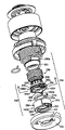
Fig. 2 is the sectional view of a specific embodiment of tension device of the present invention;
Fig. 3 is the stereogram of stop sleeve pipe and clamp holder among Fig. 2;
Fig. 4 is the stereogram of braking clip among Fig. 2;
Fig. 5 is the sectional view of another specific embodiment of tension device of the present invention;
Fig. 6 is the erection drawing of tension device among Fig. 5;
Fig. 7 is the erection drawing of another specific embodiment of tension device of the present invention;
Fig. 8 is a sectional view, illustrate top the clip sleeve pipe structure and be shown in relative installation relation among Fig. 7 with the bottom sleeve of bottom, the cross section is along a tangent plane through the tenon of the clip sleeve pipe on top, and the straight line 8-8 in Fig. 7 sees towards the pivot arm and illustrates;
Fig. 9 is the sectional view of another specific embodiment of tension device of the present invention;
Figure 10 is the sectional view of another specific embodiment of tension device of the present invention; With
Figure 11 be among Figure 10 tension device along the sectional view of straight line 11-11.
Embodiment
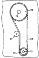
Fig. 1 illustrated a kind of Timing Belt system that is used for internal-combustion engine.A toothed belt sprocket wheel 112 is fixed in the crankshaft 113 of motor, and described sprocket wheel 112 drives an inner toothed belt 114.Described toothed belt 114 links (and driving) toothed sprocket wheel 116 in second outside, described sprocket wheel 116 is fixed on the camshaft 118 of motor, and thereby makes its rotation.One as tension device 10 of the present invention to install with the relation of belt 114 tensionings.
As shown in Figure 2, tension device 10 is installed in one by one usually to be formed around the belt pulley 12 on the ball bearing assembly 13 of a pivot arm 20 circumferential extensions, and described pivot arm 20 off-centre are installed on the pivot 16 pivotally, such as utilizing an axle journal.In other words, belt pulley 12 is around the spin axis that extends through ball bearing assembly 13 centers 15 rotations of himself, and pivot arm 20 (have therewith pivot belt pulley 12) pivots around the longitudinal axis 16c of pivot 16, and described axis 16c is usually with spin axis 15 intervals of belt pulley 12 and be arranged in parallel.
Described pivot 16 has the hole 16b that vertically runs through its center, and a construction bolt (figure does not show) that passes described hole is fixed to the tension device assembly on the motor.Pivot 16 is connected on the base plate 30 by press fit, and in preferred construction, base plate 30 has a center protuberance 31 to strengthen the press fit between base plate and the pivot.
Torsion-coil spring 18 is around the bottom (as shown) of tension device and can be installed between pivot arm 20 and the base plate 30 with turning round, an one spring joint tongue 18a enters in the groove 22 of a correspondence of pivot arm 20, and another spring joint tongue 18b stretches in the groove 33, and described groove 33 is located in the outward edge 32 of upwardly extending base plate 30.In the process of assembling tension device 10, before this pivot arm 20 was brought to its final axial position, described pivot arm 20 was with respect to base plate 30 rotations, thereby preloaded spring 18 makes pivot arm 20 setover rotatably to the free arm position.Thrust washer 14 and in pivot arm 20 rotation, reduces the friction between these Component between the flange 16a of pivot arm 20 and pivot 16.
In a preferable shape, clamp holder 60 by means of the outstanding position 56 of external flange form and on stop sleeve pipe 50 the groove section 54 of circumferential extension, directly interconnect with described stop sleeve pipe 50, these outstanding positions 56 and groove section 54 are mated with an interior groove 68 and an inner loop 67 on clamp holder 60 respectively.Stop sleeve pipe 50 ends that outstanding position 56 and groove section 54 are set on it are divided into several narrow, parts 59 flexible, finger-like by means of axial slots 53, as shown in Figure 3.Because finger portion 59 radially is flexible, when described two parts were assembled in together, outstanding position 56 was forced to the inner loop 67 of inwardly passing through clamp holder 60, bounces back into initial position separately then.Outstanding position, ring and corresponding groove are meshing with each other, and will axially lock together stop sleeve pipe 50 and clamp holder 60, rotate relative to one another and permit them simultaneously.Stop clip sleeve pipe 50 and clamp holder 60 have with gap and match, to allow the motion that rotates freely between these two elements.The stop sleeve pipe is made by flexible material, as nylon, to promote that so interior curve is returned with outside bullet.
Axle sleeve 100 is inserted in the stop sleeve pipe 50, inwardly subsides in cycle running life of tension device, to prevent outstanding position 56.Described axle sleeve 100 can also increase the integral rigidity of described stop sleeve pipe 50, particularly in the rotatablely moving of its stop arm.
Described clip 70 is designed for firmly grasps described pivot 16, via pad or braking footwear linear element 71, with a power that preestablishes size, basically or " selectively " clip 70 and then clamp holder 60, be fastened on the described pivot 16.Described clip 70 is designed to firmly grasp pivot 16 with enough big power, the feasible surface friction drag that overcomes between shim elements 71 and the pivot 16, and described clip 70 (and then clamp holder 60) is rotated, with respect to the needed level of torque of the friction slip of axle pivot 16 be: 1) be higher than by the caused torque of belt force, otherwise produce helping jumping under the rack member, but 2) when the torque loads of the maintenance moment of torsion that is subjected to being higher than designed clip 70, it allows clip 70 (and then clamp holder 60) rotation.Preferably, clip 70 is to adopt the high-yield strength anticorrosion material with 17-4 stainless steel and so on to make, and permitted its spring element and have maximum deflection before reaching the preload that needs.Selectively, also can adopt high-intensity carbon steel or tool steel to make described clip, and on parts, apply and execute corrosion-inhibiting coating.
As shown in Figure 4, in a preferred form, described clip 70 is similar letter " C ", and has a pad or footwear linear element 71 at each end.When clip 70 was manufactured into this form, described clip 70 preferably had a positioning key 72, to help the described clip in location and to guarantee it and clamp holder 60 engagements.Described frictional clamp 70 is assembled in the groove 73, and described groove 73 is around clamp holder 60 circumferential extension and partly radially extend into described clamp holder 60 partly.Pad 71 is by hole 74 assemblings, and described hole 74 is from the bottom of groove 73, and one the tunnel passes the wall (hole on the arbitrary limit of clamp holder) of clamp holder 60, and thereby the side that can firmly grasp pivot 16.In addition, described positioning key 72 is installed in the sulculus (invisible), and described sulculus is set in place between the rib 75 (can only see in Fig. 3) in groove 73.Like this, positioning key 72 helps frictional clamp 70 to locate in clamp holder and keeps its position.
Above at least one place that is connected to each other part, stop sleeve pipe 50 and clamp holder 60 have columnar outer surface 52 and 62 respectively, and have identical diameter.Described clutch spring 80 is used press fit and is installed in columnar surperficial 52 and 62 top.One end of clutch spring 80 is an axial joint tongue 82, described joint tongue 82 is inserted in the axially extended hole 51, described hole 51 is arranged in an axial joint tongue 50a who stretches out from stop sleeve pipe 50, and joint tongue 82 makes clutch spring 80 with 50 rotations of stop sleeve pipe.Described clutch spring 80 and two cylinderical surfaces 52 and 62 are realized the one-way clutch functions: when stop sleeve pipe 50 in a direction with respect to clamp holder 60 rotations, be that described belt pulley 12 and pivot arm 20 are when belt 114 rotations, described clutch spring 80 rotates slidably with respect to clamp holder 60, and almost there is not resistance, but the stop sleeve pipe rotates in the opposite direction, when being belt pulley 12 and pivot arm 20 away from belt 114 rotations, clutch spring 80 will compress three all parts (stop sleeve pipe 50, clamp holder 60 and clutch spring 80).And they are locked together.Particularly, the direction of coiling of described clutch spring 80 selects to make that (itself and pivot arm 20 rotate stop sleeve pipe 50 together, as what hereinafter describe in detail) can be with respect to clamp holder 60 position of free arm (just towards) rotation freely on the direction that described belt drives, but described clutch spring 80 will shrink, at stop sleeve pipe 50 (by pivot arm 20) in the tension on belt rotated position of minimum, make clip act on cylinderical surface 52 and 62 rigidly downwards, thereby prevent that stop sleeve pipe 50 from rotating on the direction of the tension on belt of minimum with respect to clamp holder 60.
Act on the power between pivot arm 20 and the stop sleeve pipe 50, and those act on the power between stop sleeve pipe 50 and clamp holder 60, can axially press to base plate 30 to clamp holder 60.Therefore, the lower surface of clamp holder 60 preferably is set to provide a good thrust bearing surface.
The layout that depends on helical spring 80, described spring clutch can constitute and configuration with diverse ways.The ability that is appreciated that described clutch spring transmission torque depends on the quantity that is configured in each lip-deep circle circle.If there is sufficient axial space to be used to hold some circle circles, can be placed on clutch spring 80 on each stop sleeve pipe 50 and the clamp holder 60 fifty-fifty fifty-fifty or almost.Yet if axial space is limited, one of columnar surface can be done shortlyer, and clutch spring can use a joint tongue with specific engaging of element, as illustrated in Fig. 2.Yet, even in the sort of situation, at least two circle circles are set on each columnar surface preferably still, act on the size of the power on the joint tongue with minimizing.In addition,, preferably provide a stop sleeve pipe that has an annular lip 50c in order to improve the control of clutch spring to the slip rotation aspect of free arm position, described annular lip 50c extend enough far to cover at least one circle circle clutch spring 80.Described annular lip 50c prevents that the circle circle of clutch spring from beginning exceedingly to launch at spring before sliding with respect to clamp holder 60.
A cavity 21 is arranged in the described pivot arm 20, and the axial joint tongue 50a of described stop sleeve pipe 50 can enter this cavity 21.Though described cavity 21 can be set to drive fit with joint tongue 50a, preferably described cavity 21 can be bigger slightly than described axial joint tongue 50a, can rotate freely slightly with respect to stop sleeve pipe 50 to allow described pivot arm 20.In order to make the minimise wear of back on the stop device 40, the tolerance of general " play " of recommending rotation at least approximately with by the caused arm motion of the thermal expansion of motor and/or measure identical by the move rotation of caused arm vibration of motor.This angular range will change because of the structure of each motor is different, usually between 20 ° to 50 °.Also be provided with a hexagonal hole 23 in the described pivot arm 20, can insert a corresponding tool in described hexagonal hole 23, such as the device of an Allen wrench (not shown) or any other shaft-like or handle shape that is suitable for, the opening 14a that described instrument can pass in the thrust washer 14 is inserted in described hexagonal hole 23.
Fig. 5 and Fig. 6 look out the another kind of possible structure of tension device of the present invention.Its structure is similar with structure shown in Fig. 2, but at the structure of back stop device 140 with install and to have some to change aspect the preparation of clip (not shown), it can be made up of the mechanical device that can pin the pivot arm arbitrarily with respect to the fixed component of tension device rotatably.Particularly, in the stop device 140 of back, some feature of stop sleeve pipe 150 and clamp holder 160 is squeezed (comparing with aforesaid specific embodiment), can be fixed in the hole 161 in clamp holder 160 (rather than as shown in Figure 2 in stop sleeve pipe 50) with the axle spring joint tongue 182 of permitting clutch spring 180 ends.Therefore, preferably, the cylindrical outer surface 152 of stop sleeve pipe 150 is longer than the cylindrical outer surface 162 of corresponding clamp holder 160, to hold the spring circle circle of suitable quantity thereon, be necessary on clamp holder 160, to form exterior protrusions 166 and outer grooves 164, and on stopping device 150, form inner loop 157 and the internal recess 158 that is complementary or wants to mesh.Correspondingly, as shown in Figure 6, be provided with axial slit 163 in clamp holder 160, described slit 163 forms flexible finger piece 169, so that the part assembling.Similarly, in clamp holder 160, be provided with the lip 160c that restriction clutch spring 180 excessively launches.Because the possibility that side pressure acts on the clamp holder 10 is significantly smaller than the possibility that acts on the stop sleeve pipe 150, and, any axle sleeve is set under the high torque (HT) condition so can cancel between clamp holder 160 and pivot 16 because 160 needs of clamp holder rotate with respect to pivot 16.
In addition, in this specific embodiment, described clamp holder 160 and frictional clamp 170 are configured so that frictional clamp 170 is assemblied in the groove 173, and groove 173 extends through a groove of clamp holder 160 for diameter, and pad 171 exposes with the side surface with pivot 16 and engages.Positioning key 172 is outwards given prominence to (rather than embodiment as shown in Figure 4 is equally inside outstanding) from frictional clamp 170, and cooperates with the radial groove 176 that extends perpendicular to groove 173, so that described frictional clamp 170 is correctly located and remained in the described groove 173.By frictional clamp 170 being pushed in the groove 173 to the side, align up to positioning key 172 and groove 176, make described frictional clamp 170 be inserted among the clamp holder 160, radially move described frictional clamp then, make positioning key 172 be engaged among the radial slot 176.
Clip is installed is convenient to the installation of tension device on motor.Particularly, when pivot arm 20 forward near or until the stop dog position of outermost back the time, usually, when tension device is positioned on the assembly line during manufacture, described clip is inserted in the respective aperture in the element of pivot arm 20 and some fixed element or tension device 10 (for example, base plate 30).When the installation clip was inserted into, described pivot arm 20 can not rotate the position of leaving factory's initial setting, up to removing the installation clip.
Fig. 7 and Fig. 8 look out another possible structure of tension device of the present invention.Structure is similar shown in its unitary construction and Fig. 5 and Fig. 6, but frictional clamp 270 is different with the structure of clamp holder 260.Particularly, the frictional clamp 70 and 170 that frictional clamp 270 is configured in the more above-mentioned specific embodiment more resembles a trip ring, and frictional clamp 270 is configured to compare previously described two specific embodiments, makes with the rubbing contact scope of tension device pivot bigger.For instance, frictional clamp 270 preferably contacts with about zone more than 270 ° on the pivot circumference.
Preferably, described frictional clamp 270 is to adopt the stainless steel spring silk to make.Though the size of the spring thread of friction spring clip 270 will and can keep the needed level of torque of frictional clamp to change according to antagonism certainly, as a reference, as shown in the figure, the create friction spring thread of clip 270 has the square cross section of one 3 millimeters x3 millimeter.Have been found that frictional clamp 270 compared to above-mentioned frictional clamp 70 and 170, easier usually manufacturing, intensity is better, and more lasting opposing torque performance is provided.
In addition, when sliding rotatably, described clip 270 is compared with clip shown in Figure 6 with Fig. 4, and is variant slightly.When joint tongue 271a is when being promoted by the clip sleeve pipe 260a on top, will cause that clip 270 launches slightly, thereby reduce clamping force and the surface friction drag when rotating.In other words, under expectation will rub the situation that keeps discharging, friction catch can be configured at least partially and launch.Torque when therefore, the variation of friction factor will discharge/slide generation to friction catch has the effect that reduces.
In order to hold frictional clamp 270, clamp holder 260 is made of two parts, that is to say the stop sleeve pipe 260a on a top and the bottom sleeve 260b of a bottom.As in Fig. 8 clearer demonstration, described frictional clamp 270 is installed in " pocket " that the outer wall 284 by shoulder surface 283 and clip sleeve pipe 260 defines.
Three bars or tenon 285a, 285b and 285c extend to form from outer wall 284, and the relevant portion of outer wall 284 correspondingly " enhancing ".The part at tenon 285c place is provided with a hole (invisible) on the outer wall 284, and carries out the transition to a groove 286 that is arranged in the radially-outer surface 287 of tenon 285c in the lower surface (as the orientation of the clip sleeve pipe 260a among Fig. 7) of outer wall 284 by the hole.Described hole and described groove 287 are configured to hold the whole or almost whole length of the axially extended bottom joint tongue 282 of clutch spring 280---to be fit to keep the mode of bottom joint tongue 282, its with respect to clip sleeve pipe 260a rotatably fixed clutch spring 280 (and, correspondingly, in case fit together, with respect to clamp holder 260).
Two grooves or groove 288a and 288b are located in the outer wall 284 of clip sleeve pipe 260a, are set to hold the axial joint tongue 282 of clutch spring 280 on any one side of tenon 285c.As shown in Figure 8, groove or groove 288a and 288b hold the end of the joint tongue shape of frictional clamp 270.One of groove 288a relative narrower, hold the respective end portions 271a of frictional clamp 270 so that adopting is slidingly matched, its frictional clamp 270 end 271a are fixing reliably in position, yet, the relative broad of another groove 288b is so that hold assembling deviation.
Wish that generally clip sleeve pipe 260 has relative high friction coefficient with the part of clutch spring 280 engagements, to help clutch spring 280 grasping clips sleeve pipe 260a.On the other hand, wish that also the part that 250 rotations of clip sleeve pipe 260 and stop sleeve pipe cooperate has relatively low friction factor, so that the relatively rotating of two parts.In addition, the resilient fingers 269 of clip sleeve pipe 260a should have sufficient elasticity, when stop sleeve pipe 250 and clip sleeve pipe 260 are pressed together, can not fracture.Consider various factors, clip sleeve pipe 260 can adopt the mould-forming manufacturing together of different materials, every kind of material has needed friction factor and gentle a piece of wood serving as a brake to halt a carriage degree reaching these targets, and perhaps described clip sleeve pipe can be made by the material (as nylon 46) that a kind of while meets described three conditions as far as possible.
Illustrational as further institute in Fig. 7 and Fig. 8, bottom sleeve 260b has an end " wall " 291 that is substantially a columnar outer wall 290 and an annular, and its part that exposes provides the lower surface 289 of thrust bearing effect.Outer wall 290 small part 292 radially outwards thereon protrude, with in assembling clamp holder 260, for clip end 271a and the 271b that the joint tongue shape is installed provides the space.In addition, a groove 293 extends axially at annular end wall 291, and in assembling clamp holder 260 (with the remaining part of tensioning device structure), tenon 285c (being placed with the axial joint tongue 282 of described clutch spring 280 in the groove 286 of described tenon 285c) extends into groove 293 (but being no more than supporting surface 289).Extra two grooves (invisible) are the blind holes of being located in the upper face of annular end wall 291, and are positioned for when being assembled together the part of clamp holder 260, hold other two tenon 285a and 285b.
The outer wall 290 of bottom sleeve 260b has a crimping 294 that extends circumferentially around the internal surface of outer wall 290, near the top edge (according to illustrated direction) of outer wall 290.Locked groove 295 engagements of the circumferential extension that crimping 294 and forms around the outer wall 284 of described clip sleeve pipe 260.Therefore, in case frictional clamp 270 correctly is placed in " pocket " of clip sleeve pipe 260a, by clip sleeve pipe 260a and bottom sleeve 260b are pressed onto together, among crimping 294 is snapped to locking slot 295, and tenon 285a, 285b and 285c are arranged in the annular end wall 291 corresponding grooves of bottom sleeve 260b, and make clamp holder 260 installation in position.
Described bottom sleeve 260b also has the annular lip (invisible) on a top, and this lip is around the edge, top (as the orientation among Fig. 7) of outer wall 290, and structurally, this lip and the lip 50c shown in Fig. 2 or lip 160c shown in Figure 5 are similar.Annular lip is sized in the time of the assembling tension device, can hold the circle circle of clutch spring 280 bottoms, thereby prevents that the circle circle of clutch spring 280 from excessively launching before spring slides with respect to clamp holder 260.
The working order of described tension device (with, particularly, back stop device 40,140 or 240) is as described below.In the first installation process of described tension device and belt, the general use passed the hole 16b of pivot 16 and is screwed into bolt (figure does not show) in the motor, and described tension device is installed to appropriate location on the motor, described bolt.If tension device has an installation clip 11, then described pivot arm 20 has been positioned at minimum tightened position, so that the installation of belt.Otherwise, if tension device is not installed clip (particularly in the process of using on-the-spot installation tensioner again, in the absence of described clip), the personnel of installation tensioner must move into pivot arm 20 or close minimal belt tightened position, so that a belt is installed on the tensioner pulley 12.This can be by inserting an Allen wrench and realizing to the described pivot arm 20 of the tension on belt rotated position of minimum in the hexagonal hole 23 of pivot arm 20.If between pivot arm 20 and stop sleeve pipe 50,150 or 250, some rotations " play " are arranged, and because at axially joint tongue 50a, 150a or 250a be located at the gap that has some rotations between the cavity 21 in the pivot arm 20, unique initial rotation resistance that setter can be felt comes from main spring 18.When " play " when straining, setter also must pivot stop sleeve pipe 50,150 or 250.Because stop sleeve pipe 50,150 or 250 via frictional clamp 70,170 or 270 partial rotation be fixed on the pivot 16, setter also must overcome clip 70,170 or 270 and pivot 16 between fricative rotational resistance.This surface friction drag designs enough greatly with the torque of opposing by the caused belt induced force of the backward rotation of motor, but this surface friction drag is enough little simultaneously, to allow the setter pivot arm 20 that rotates backward.Therefore, so setter can move to minimum tension on belt position to pivot arm 20 all the time, and in this position, belt is installed on various sprocket wheels and the belt pulley.
After belt is installed to various belt pulleys, must allow pivot arm 20 (and then belt pulley 12) freely to pivot, so that suitable belt tension to be provided to belt.If tension device has an installation clip 11, setter just removes clip 11.If arm and belt pulley assembly manpower rotate to minimum tightened position, pressure on the setter releasing tool (Allen wrench) and permission main spring 18 make pivot arm 20 (with belt pulley 12) rotate to belt.In case belt pulley 12 stably leans against on the belt, the instrument of can removing is finished installation process.Under arbitrary in both cases situation, because the back stop device does not produce any tangible resistance to pivot arm 20 to the rotation of arm position freely, so main spring 18 can provide the motion of the arm of necessity to belt (correspondingly, providing necessary belt tension).
Usually, tension device sometimes will run into such operating conditions: the belt load on the belt pulley increases, and then, (just leave on the direction of belt) in the opposite direction and on pivot arm 20, apply torque.Two kinds of this type of operating conditionss are cold start-up and motor backward rotation after the normal thermal expansion of motor.In each of these examples, if there is any rotation " play ", pivot arm 20 is with stop device counterrotating backward, up to axially extended joint tongue 50a, the 150a or the 250a that contact stop sleeve pipe 50,150 or 250 at the corresponding end-faces of pivot arm 20 hollow cavities 21; Otherwise (that is to say, when being drive fit between described axially extended joint tongue and the described cavity), described pivot arm will can not rotate with respect to described stop sleeve pipe.Subsequently, because the pivot arm will be connected to frictional clamp via stop sleeve pipe, spring clutch and clamp holder, this will prevent the counterrotating (promptly being rotated away from described belt) of pivot arm 20, and frictional clamp provides enough big surface friction drag to limit this kind backward rotation to avoid jumping tooth, at this moment allow manpower spin friction clip, and thereby make tensioner arm install easily or reinstall.
In above-mentioned specific embodiment, a spring clutch provides required one-way function.Yet any known non-return device (such as one-way roller clutch, ratchet and ratchet, or the like) can be used to a friction brake and the stop sleeve pipe is connected to each other.Similarly, replace clip, friction catch can be any known configuration by means of friction-produced braking force.
Selectively, illustrational as Fig. 9 institute, replace friction stopping device, described tension device can use a hydraulic pressure installation structure, described hydraulic pressure installation is designed to produce enough resistances and enough maintenance power, with prevent back stop device reversing motion and therefore arm leave the rotation (this of arm kind of rotation can be jumped tooth) of belt.This kind hydraulic pressure installation can be any known hydraulic pressure installation or, for instance, as patent application 09/547 just on the docket, No. 108 disclosed a kind of viscous coupling assembly (applications on April 11st, 2000, its disclosed content is herein with reference to quoting), still can obtain the advantage of various features of the present invention.Adopt this kind Coupler assembly 340, between a member 381 and one second member 396 cohesive material 370 is set, described member 381 is fixed on the outer surface of pivot 16 bottoms, and described second member 396 can be with respect to member 381 rotations.(be the purpose of illustration, described second member 396 is depicted as unibody construction, but it can be a two-piece construction---the first half and Lower Half, and as 09/547,108 kind of cited structure of patent application of above-mentioned reference.) be applied to suddenly on the pivot arm 320 when torsional load, and when being delivered to second member 396 via stop sleeve pipe 350 and clutch spring 380, cohesive material 370 stops second member 396 with respect to member 381 rotations (because its viscosity), but when the load that reverses little by little and/or continuously applied, cohesive material 370 allowed second member 396 with respect to member 381 rotations.
The stop sleeve pipe 350 of lacking some than aforesaid stop sleeve pipe is connected to second member 396 in the mode similar to aforesaid way.Particularly, interconnecting between two elements axially locks together them, but allows an element with respect to another element rotation.As the clutch spring among above-mentioned each embodiment stop sleeve is grasped in clamp holder, clutch spring 380 is grasped in stop sleeve pipe 350 on second member 396 in identical substantially mode.
By between pivot arm 320 and stop sleeve pipe 350, setting rotation " play ", as described above (such as, the cavity 321 of axial joint tongue 350a by will inserting stop sleeve pipe 350 is made greatlyyer than described joint tongue 350a), the vibratory output that hydraulic pressure installation stood reduces.This has prolonged the working life of described hydraulic pressure installation.
Another specific embodiment of tension device of the present invention has been shown in Figure 10 and Figure 11.In this specific embodiment, described " stop sleeve pipe " 450 is as a whole with the extension design of tension device pivot arm 420.In this specific embodiment, clutch spring 480 is directly connected to tension device pivot arm 420 effectively, and the axial joint tongue 482 of clutch spring 480 extends in the cavity 421 of tension device pivot arm 420.(in a selectable structure, corresponding, the bottom of clutch spring 480 can be fixed to " clip sleeve pipe " 460 by rights.)
As clearer illustrating among Figure 11, friction stopping device 470 is designed to a cylinder around pivot 16 bottoms, and has removed a sector 472 of described cylinder." clip sleeve pipe " 460 is coaxial with the outer surface of friction stopping device 470 and match.Clip sleeve pipe 460 has a key 462, and described key 462 inwardly radially extends from the internal surface of clip sleeve pipe 460, and is assemblied in the sector 472 that friction stopping device 470 removes.Like this, when clip sleeve pipe 460 has rotated enough tolerance, when touching the wall 473,474 that is removed sector 472 and applying enough power.Force friction brake 470 to rotate around pivot.
It will be appreciated, of course, that by pivot arm 420 via clutch spring 480 transmitting torques to clip sleeve pipe 460, and make clip sleeve pipe 460 with respect to 16 rotations of tension device pivot.If the quantity of the circle circle that twines around " stop sleeve pipe " 450 (being the center of an extension of tensioner arm 420 in essence) is abundant, if and/or clutch spring is as the illustrated axial joint tongue of placing reliably in cavity 421 482 that has of giving an example, described clutch spring 480 will be followed pivot arm 420 motions of tension device continuously.
Yet, preferably, have small " free travel " to rotate freely certain amount (corresponding to the thermal expansion of motor and/or corresponding to the dynamic vibration of belt drives) to allow tensioner arm 420 for making tension device.This kind free travel may be subjected to one or two the influence in two factors, and the both is illustrated.At first, by the key 462 of clip sleeve pipe 460 being made narrower, and make pivot arm 420 have a certain amount of rotation play than the sector 472 of removing.In addition, have bigger diameter, as shown in the figure, can have certain rotation play in the described assembly by the circle circle that makes clutch spring 480.In case this is because pivot arm 420 begins to rotate clutch spring 480, can be before clip sleeve pipe 460 produce any main rotating torques at described clutch spring, the larger-diameter circle circle of clutch spring 480 must be retracted to surface in it and contact.As another possibility (not shown), the rotation play can be positioned at the quantity of the clutch spring on " the stop sleeve pipe " 450 (arm core) and form a cavity 421 as circular arc by reducing (or even fully phasing out), so that tensioner arm 420 is forcing clutch spring can rotate certain amount before following the arm rotation.
Though, in the above in the description and the illustrational specific embodiment of the invention, described back stop device stops rotation by back stop device and pivot 16 frictional fit, but, described tension device also may be constructed like this: the back stop device is by stoping rotation with the part of a fixed-site rather than with pivot 16 frictional fit, the part of described fixed-site such as base plate 30 or even motor itself (such as, under the situation that base plate is not set).These specific embodiments and other specific embodiment all are considered within the scope of the claims.
Claims (29)
1. belt stretcher (10) that is used for motor vehicle engine, it comprises:
A pivot (16);
A pivot arm (20) that is pivoted on the described pivot (16);
A belt pulley (12) that is bearing in rotatably on the described pivot arm (20);
The spring (18) of a described pivot arm of bias voltage (20) on the direction of belt tension; With
Stop device (40 after one, 140,240), it comprises an overrunning clutch member (80,180,280) and a friction catch member (70,170,270), described friction catch member relatively is installed on the anchor portion by frictional fit, and described anchor portion is fixed with respect to described motor vehicle engine, be placed in to described overrunning clutch member (80,180,280) running described pivot arm (20) and described friction catch member (70,170,270) between, described overrunning clutch member (80,180,280) structure and position are set to allow described pivot arm (20) freely to pivot on described belt tension direction
It is characterized in that
The structure of described overrunning clutch member and position are set to stop described pivot arm going up in the opposite direction with respect to described friction catch member (70 with described belt tension side, 170,270) pivot, wherein said pivot arm can freely rotate with the certain play amount that exists therebetween with respect to described overrunning clutch member.
2. tension device as claimed in claim 1, it is characterized in that: described friction catch member (70,170,270) and the degree of the frictional fit between the described anchor portion, in the torque that is large enough to cause with the belt load that is subjected at described pivot arm (20) under the normal engine running situation, stop described pivot arm (20) with the rightabout pivot of described belt tension direction, and be small enough to allow rotating described pivot arm (20) going up manpower in the opposite direction with described belt tension side.
3. tension device as claimed in claim 2 is characterized in that: described friction catch member (270) is set to pivot in the described pivot arm (20) going up manpower in the opposite direction with described belt tension side, launches at least in part.
4. tension device as claimed in claim 1 is characterized in that: described anchor portion comprises the part of stop device (40,140,240) installation position, the upward close back of described pivot (16).
5. tension device as claimed in claim 1 is characterized in that: described play comprises a predefined rotational component, and described rotational component is identical with the rotation number of degrees of the pivot arm motion that thermal expansion by described motor causes.
6. tension device as claimed in claim 1, it is characterized in that: described play comprises a predefined rotational component, the rotation number of degrees of described rotational component and the pivot arm motion that causes by the thermal expansion of described motor, and identical by the combination of the rotation number of degrees of the caused pivot arm motion of vibration dynamic, that cause by motor of described pivot arm (20).
7. tension device as claimed in claim 1 is characterized in that:
Described friction catch member (70,170,270) comprises a frictional clamp member,
Described back stop device (40,140,240) comprises a pair of rotating member of axially aligning (50,150,250; 60,160,260), described rotating member is provided with around described pivot (16), described rotating member one of them (50,150,250) with described pivot arm (20) engagement, another of described rotating member (60,160,260) comprise a clamp holder that meshes with described frictional clamp member, at least one in the described rotating member has a cylindric part, and
Wherein said back stop device (40,140,240) further comprise a clutch spring, one end of described clutch spring is enclosed within on described one of them individual cylindric part of described rotating member, and the other end of described clutch spring (82,182,282) be connected in the described rotating member another, thus, described clutch spring allows described rotating member to rotate relative to one another in one direction, and stops described rotating member to rotate relative to one another in the opposite direction.
8. tension device as claimed in claim 7, it is characterized in that: described clamp holder comprises the clip sleeve component (260a) on a top and the bottom sleeve member (260b) of a bottom, and wherein said frictional clamp member is between the bottom sleeve member of the clip sleeve component on described top and bottom.
9. tension device as claimed in claim 7 is characterized in that: described clutch spring has a joint tongue, and described clutch spring anchors on the described rotating member that meshes with described pivot arm (20) by this joint tongue.
10. as claim 7 or 8 described tension device, it is characterized in that: described clutch spring has a joint tongue, and described clutch spring anchors to described clamp holder by this joint tongue.
11., it is characterized in that: described a pair of rotating member (50,150,250 as each described tension device among the claim 7-9; 60,160,260) directly axially be connected to each other each other.
12. a belt stretcher (10) that is used for motor vehicle engine, it comprises:
A pivot (16);
A pivot arm (20,420) that is pivoted on the described pivot (16);
A belt pulley (12) that is bearing in rotatably on the described pivot arm (20,420);
The spring (18) of a described pivot arm of bias voltage (20,420) on the direction of belt tension; With
Stop device after one (40,140,240), it comprises an arm mate (50a, 150a, 250a, 450), a friction catch member (70,170,270,470) and an overrunning clutch member (80,180,280,480),
By allowing described overrunning clutch member (80,180,280,480) and described friction catch member (70,170,270,470) slide relative between, described back stop device (40,140,240) described pivot arm (20,420) is freely pivoted on described belt tension direction
It is characterized in that
By described pivot arm (20,420) by described arm mate (50a, 150a, 250a, 450) engagement, described friction catch member (70,170,270,470) with the friction engagement of an anchor site fixing with respect to described motor, and described friction catch member (70,170,270,470) with described arm mate (50a, 150a, 250a, 450) between overrunning clutch member (80,180,280,480) interlocked usefulness, described back stop device (40,140,240) stop described pivot arm (20,420) pivoting in the opposite direction with described belt tension side, and
Comprise a pair of member of axially aligning cylindraceous, it is around described pivot (16) setting and axially be connected to each other one of them of described member cylindraceous and described pivot arm (20 each other, 420) engagement, another of described member cylindraceous comprises the described friction catch member (70,170,270 of supporting, 470) clamp holder, and described overrunning clutch member (80,180,280,480) comprise a clutch spring, described clutch spring is enclosed within on the member of described pair of cylinders shape.
13. tension device as claimed in claim 12, it is characterized in that: described friction catch member (70,170,270,470) and the degree of the described friction engagement between the described anchor portion be, be large enough to when being subjected to torque that the belt load under the normal engine running situation causes at described pivot arm, stop described pivot arm (20,420) pivoting in the opposite direction with described belt tension side, and be small enough to allow rotating described pivot arm (20,420) going up manpower in the opposite direction with described belt tension side.
14. as claim 12 or 13 described tension device, it is characterized in that: described anchor portion comprises the last part near stop device (40,140,240) installation position, back of described pivot (16).
15., it is characterized in that: between described pivot arm (20) and described member cylindraceous are one of described, be provided with certain play as claim 12 or 13 described tension device.
16., it is characterized in that as claim 12 or 13 described tension device:
Described friction catch member (70,170,270,470) comprises a frictional clamp member,
Wherein said clutch spring allows described member cylindraceous to rotate relative to one another in one direction, describedly rotates relative to one another in the opposite direction for member cylindraceous and stop.
17. as claim 12 or 13 described tension device, it is characterized in that: described clamp holder comprises the clip sleeve component (260a) on a top and the bottom sleeve member (260b) of a bottom, and wherein said friction catch member (270) is between the bottom sleeve member of described upper clamp sleeve component and bottom.
18. as claim 12 or 13 described tension device, it is characterized in that: described clutch spring is connected on the member described cylindraceous that meshes with described pivot arm (20).
19. as claim 12 or 13 described tension device, it is characterized in that: described clutch spring is connected on the member described cylindraceous that comprises a clamp holder.
20. as claim 12 or 13 described tension device, it is characterized in that: (50a, 150a are provided with certain play between 250a) at described pivot arm (20) with the mate of the described member cylindraceous of described pivot arm (20) engagement.
21. the belt stretcher of an automobile (10), it comprises:
One is installed in the pivot (16) on the motor reliably;
One is pivoted on the pivot arm (20) on the described pivot (16);
The belt pulley (12) of one swivel bearing on described pivot arm (16);
One structure and the spring (18) that is set to the described pivot arm of bias voltage (20) on the direction of belt tension; With
One back stop device (40,140,240,340), stop device running ground, described back is arranged between the anchor portion that described pivot arm (20) and fixes with respect to described motor, described back stop device is constructed and is set to allow described pivot arm (20) freely to pivot on described belt tension direction
It is characterized in that
Described back stop device also constructs and is set to stop described pivot arm (20) pivoting in the opposite direction with described belt tension side,
Wherein, described pivot arm (20) and described back stop device (40,140,240,340) are equipped with the rotation play for one of between setting preestablishes and size is limited; And
Described back stop device comprises a pair of stopper element and overrunning clutch member around described pivot (16) setting, wherein said stopper element is interlocked and makes that one of them of described stopper element can be with respect to another rotation of described stopper element, the engagement of described stopper element one of them and described pivot arm (20), and another of described stopper element is connected with described anchor portion, described overrunning clutch member (80,180,280,380) comprise a clutch spring that is enclosed within on the described pair of stopper members, clutch spring allows described stopper element capable of pivoting relative to each other in one direction, and stop described stopper element capable of pivoting relative to each other on an opposite direction, one of described stopper element has at least one axial slots (53,163,263).
22. tension device as claimed in claim 21 is characterized in that: the friction catch member (70,170,270) of another in the described stopper element by being meshed with described anchor portion is connected with described anchor portion.
23. tension device as claimed in claim 21 is characterized in that: another in the described stopper element is connected with described anchor portion by a hydraulic pressure installation (370).
24. tension device as claimed in claim 23 is characterized in that: described hydraulic pressure installation (370) comprises cohesive material.
25. the belt stretcher of an automobile (10), it comprises:
One is installed in the pivot (16) on the motor reliably;
One is pivoted on the pivot arm (20) on the described pivot (16);
The belt pulley (12) of one swivel bearing on described pivot arm (20);
One structure and the spring (18) that is set to the described pivot arm of bias voltage (20) on the direction of belt tension; With
One back stop device (340), stop device running ground, described back is arranged between the anchor portion that described pivot arm (20) and fixes with respect to described motor, described back stop device is constructed and is set to allow described pivot arm (20) freely to pivot on described belt tension direction
Described back stop device, (340) comprise a pair of around described pivot, (16) stopper element of She Zhiing, (350,360) and an overrunning clutch member, described stopper element one of them, (350) with described pivot arm, (20) engagement, and another of described stopper element is connected to described anchor portion, described overrunning clutch member comprises that is enclosed within a described pair of stopper members, (350,360) clutch spring on, (380), clutch spring allows described stopper element capable of pivoting relative to each other in one direction
It is characterized in that described back stop device is also constructed and is set to utilize prevents that overrunning clutch member that described stopper element rotates in the opposite direction relative to each other from stoping described pivot arm pivoting in the opposite direction with described belt tension side, and wherein said stopper element described another (360) are connected to described anchor portion by cohesive material (370).
26. be used for optionally transmitting the rotating equipment of rotating energy or torque, it comprises:
A pair of rotating member, it axially directly connects each other, and can rotate relative to one another; With
An overrunning clutch spring that is located on the described a pair of rotating member, when a described rotating member during in the rotation of direction, described overrunning clutch spring rotation locks the rotating member of described a pair of axial interlocking, and when one of them member described in the described rotating member during in the rotation of opposite direction, described overrunning clutch spring allows the rotating member of described axial interlocking to rotate relative to one another.
27. rotating equipment as claimed in claim 26, it is characterized in that: one of them has the lip of a ring-type described a pair of rotating member, clutch spring is stated in described lip portion cover cap residence, with at a described rotating member during in the rotation of described opposite direction, the circle circle that limits described clutch spring launches.
28. rotating equipment as claimed in claim 26, it is characterized in that: the diameter of at least one circle circle of described clutch spring is bigger than the diameter of other circle circle of described clutch spring, described large diameter circle circle is before described clutch spring locks described a pair of rotating member rotatably, for a described rotating member provides a certain amount of free travel rotation.
29. rotating equipment as claimed in claim 28, it is characterized in that: one of described a pair of rotating member has the lip of a ring-type, a clutch spring part is stated in described lip portion cover cap residence, with at a described rotating member during in the rotation of described opposite direction, the circle circle that limits described clutch spring launches.
Applications Claiming Priority (2)
| Application Number | Priority Date | Filing Date | Title |
|---|---|---|---|
| US33580101P | 2001-12-05 | 2001-12-05 | |
| US60/335,801 | 2001-12-05 |
Publications (2)
| Publication Number | Publication Date |
|---|---|
| CN1599847A CN1599847A (en) | 2005-03-23 |
| CN100439758C true CN100439758C (en) | 2008-12-03 |
Family
ID=23313263
Family Applications (1)
| Application Number | Title | Priority Date | Filing Date |
|---|---|---|---|
| CNB028244214A Expired - Lifetime CN100439758C (en) | 2001-12-05 | 2002-12-03 | Timing belt tensioner with stops controlled by frictional brake |
Country Status (10)
| Country | Link |
|---|---|
| US (2) | US7507172B2 (en) |
| EP (2) | EP1451486B1 (en) |
| JP (1) | JP4508641B2 (en) |
| KR (1) | KR100933816B1 (en) |
| CN (1) | CN100439758C (en) |
| AU (1) | AU2002347150A1 (en) |
| BR (1) | BR0214737B1 (en) |
| CA (1) | CA2469497C (en) |
| DE (1) | DE60225716T2 (en) |
| WO (1) | WO2003048606A1 (en) |
Families Citing this family (67)
| Publication number | Priority date | Publication date | Assignee | Title |
|---|---|---|---|---|
| BR0214737B1 (en) | 2001-12-05 | 2011-02-22 | belt tensioner and rotary apparatus for selectively transmitting torque or rotational power. | |
| CA2593116C (en) * | 2004-06-04 | 2013-12-03 | Litens Automotive Partnership | Tensioner assembly with electronically controlled vibration clutch assembly |
| JP5074186B2 (en) * | 2004-09-01 | 2012-11-14 | ライテンズ オートモーティブ パートナーシップ | Tensioner |
| CN101107462B (en) * | 2005-01-19 | 2010-12-01 | 利滕斯汽车合伙公司 | Timing belt tensioner |
| CA2601901C (en) * | 2005-03-21 | 2013-09-17 | Litens Automobile Partnership | Belt tensioner with wear compensation |
| CN100561009C (en) * | 2005-03-21 | 2009-11-18 | 利滕斯汽车合伙公司 | Idle wheel with the feature reinstalled |
| WO2006105656A1 (en) * | 2005-04-08 | 2006-10-12 | Litens Automotive Partnership | Tensioner with molded arm |
| WO2007025374A2 (en) | 2005-09-01 | 2007-03-08 | Litens Automotive Partnership | Low profile tensioner with arcuate spring |
| FR2891039B1 (en) | 2005-09-19 | 2009-05-22 | Hutchinson Sa | POWER TRANSMISSION PULLEY |
| US7217207B1 (en) * | 2005-11-03 | 2007-05-15 | The Gates Corporation | Tensioner |
| KR101485511B1 (en) * | 2006-07-07 | 2015-01-22 | 데이코 유로페 에스.알.엘. 콘 유니코 소시오 | Pulley assembly |
| JP5162591B2 (en) * | 2006-09-01 | 2013-03-13 | ボーグワーナー インコーポレーテッド | Tensioner with two-way damper |
| DE102006059550A1 (en) * | 2006-12-16 | 2008-06-19 | Schaeffler Kg | Clamping device for a traction mechanism drive |
| DE102007015676A1 (en) * | 2007-03-31 | 2008-10-02 | Schaeffler Kg | Clamping device of a traction mechanism drive |
| CN101680515B (en) | 2007-05-01 | 2012-09-05 | 利滕斯汽车合伙公司 | Wear compensated tensioner |
| FR2923075B1 (en) * | 2007-10-29 | 2009-12-25 | Areva T & D Ag | ACTUATOR OF A SWITCH COMPRISING A FREEWHEEL COUPLING DEVICE |
| DE102008013926B4 (en) * | 2008-03-12 | 2019-07-25 | Vensys Energy Ag | Device for adjusting the angle of attack of a rotor blade of a wind turbine |
| WO2009152311A1 (en) * | 2008-06-13 | 2009-12-17 | Brady Worldwide, Inc. | Printer drive train for providing and maintaining ribbon tension |
| US20100069185A1 (en) * | 2008-09-18 | 2010-03-18 | Ward Peter Alan | Tensioner |
| JP5250889B2 (en) * | 2008-10-01 | 2013-07-31 | 日本発條株式会社 | Tensioner |
| JP4942722B2 (en) * | 2008-10-16 | 2012-05-30 | 株式会社椿本チエイン | Toothed belt pulley |
| US20100261564A1 (en) * | 2009-04-13 | 2010-10-14 | Hughes Thomas E | Rotary tensioner |
| US8523720B2 (en) * | 2009-07-02 | 2013-09-03 | Ford Global Technologies, Llc | Chain tensioner |
| DE102009052611B4 (en) | 2009-11-10 | 2018-06-07 | Schaeffler Technologies AG & Co. KG | Pulley arrangement |
| GB2478543B (en) * | 2010-03-09 | 2017-03-01 | Gm Global Tech Operations Llc | System for powering a hybrid vehicle |
| US8613680B2 (en) | 2010-04-20 | 2013-12-24 | Litens Automotive Partnership | Tensioner with spring damper |
| DE102010019066A1 (en) * | 2010-05-03 | 2011-11-03 | Schaeffler Technologies Gmbh & Co. Kg | tensioner |
| CN102959262B (en) * | 2010-06-25 | 2016-01-20 | 利滕斯汽车合伙公司 | There is the isolation belt wheel of the ability of surmounting and vibration damping ability |
| EP2613957A4 (en) | 2010-09-10 | 2014-07-23 | Litens Automotive Inc | Intelligent belt drive system and method |
| WO2013003937A1 (en) | 2011-05-13 | 2013-01-10 | Litens Automotive Partnership | Intelligent belt drive system and method |
| US8678157B2 (en) | 2011-05-25 | 2014-03-25 | Gates Corporation | Isolator decoupler |
| US8734279B2 (en) | 2011-06-08 | 2014-05-27 | Gates Corporation | Tensioner |
| WO2013131166A1 (en) * | 2011-08-08 | 2013-09-12 | Litens Automotive Partnership | Decoupler assembly |
| WO2013033822A1 (en) | 2011-09-05 | 2013-03-14 | Litens Automotive Partnership | Intelligent belt drive system and method |
| JP5673858B2 (en) * | 2011-11-25 | 2015-02-18 | 日本精工株式会社 | Rotating machine with pulley with built-in one-way clutch |
| US8932163B2 (en) * | 2012-02-20 | 2015-01-13 | Dayco Ip Holdings, Llc | Belt tensioning device with variable spring factor |
| WO2013159181A1 (en) | 2012-04-28 | 2013-10-31 | Litens Automotive Partnership | Adjustable tensioner |
| US8888622B2 (en) * | 2012-06-04 | 2014-11-18 | The Gates Corporation | Isolator decoupler |
| US9790817B2 (en) | 2012-10-22 | 2017-10-17 | Litens Automotive Partnership | Tensioner with increased damping |
| US9466749B1 (en) * | 2012-12-10 | 2016-10-11 | Nextracker Inc. | Balanced solar tracker clamp |
| CN105247243B (en) * | 2013-05-24 | 2018-01-12 | 莱顿汽车部件(苏州)有限公司 | Stretcher with oil management feature |
| US9290235B2 (en) * | 2013-06-18 | 2016-03-22 | Shimano Inc. | Bicycle derailleur |
| US9212731B2 (en) * | 2013-07-26 | 2015-12-15 | Dayco Ip Holdings, Llc | Tensioner with multiple nested torsion springs |
| US20150031484A1 (en) * | 2013-07-26 | 2015-01-29 | Dayco Ip Holdings, Llc | Tensioner with single torsion spring having multiple nested windings |
| DE112014004168T5 (en) | 2013-09-11 | 2016-06-16 | Litens Automotive Partnership | CLAMPING DEVICE WITH INCREASED CUSHIONING AND ARM-ON-BASE CUP CONFIGURATION |
| FR3011598A1 (en) * | 2013-10-04 | 2015-04-10 | Skf Ab | MECHANICAL SYSTEM WITH A UNIDIRECTIONAL CLUTCH AND ALTERNATOR COMPRISING SUCH A SYSTEM |
| EP2937598B1 (en) * | 2014-04-24 | 2020-05-13 | Litens Automotive Partnership | Tensioner with increased damping |
| EP2955414A1 (en) * | 2014-06-13 | 2015-12-16 | Aktiebolaget SKF | Tensioning device and method for assembling such a tensioning device |
| US10712234B2 (en) * | 2015-02-27 | 2020-07-14 | Purdue Research Foundation | Belt and pulley systems and methods of detecting belt damage |
| US9291253B1 (en) | 2015-03-24 | 2016-03-22 | Gates Corporation | Isolating decoupler |
| CN104989793B (en) * | 2015-05-27 | 2017-08-29 | 纽尚(宁波)汽车轴承制造有限公司 | Double variable torque shelves friction shoe type stretchers |
| US10859141B2 (en) | 2015-10-28 | 2020-12-08 | Litens Automotive Partnership | Tensioner with first and second damping members and increased damping |
| US9752628B2 (en) | 2015-12-04 | 2017-09-05 | Gates Corporation | Self-locking clutch mechanism |
| USD840879S1 (en) * | 2017-02-16 | 2019-02-19 | Miner Elastomer Products Corp. | Cushioning apparatus |
| US10570997B2 (en) * | 2017-04-25 | 2020-02-25 | Alt America Inc. | Friction type one-way high damping gauge tensioner |
| US20190107179A1 (en) * | 2017-10-09 | 2019-04-11 | Alt America Inc. | Friction Type One-Way High Damping Tensioner |
| US10774906B2 (en) * | 2018-03-27 | 2020-09-15 | Gates Corporation | Tensioner |
| MX2020000131A (en) * | 2018-07-05 | 2020-08-06 | Gates Corp | Synchronous belt drive system. |
| US11549558B2 (en) | 2018-08-01 | 2023-01-10 | Gates Corporation | Isolator decoupler |
| KR102429273B1 (en) | 2018-11-08 | 2022-08-03 | 주식회사 엘지화학 | Pulley stopper and pulley apparatus including the same |
| US11255414B2 (en) * | 2019-05-15 | 2022-02-22 | Gates Corporation | Tensioner |
| US11125305B2 (en) * | 2019-06-20 | 2021-09-21 | Gates Corporation | Tensioner |
| RU195852U1 (en) * | 2019-11-20 | 2020-02-06 | Эрвин Джеватович Умеров | Belt drive |
| WO2022260975A1 (en) * | 2021-06-07 | 2022-12-15 | Gates Corporation | Pivot shaft tensioner assembly |
| IT202100014756A1 (en) * | 2021-06-07 | 2022-12-07 | Dayco Europe Srl | TENSIONER WITH DOUBLE DAMPING SYSTEM FOR A TIMING BELT DRIVE |
| CN113479574B (en) * | 2021-07-28 | 2023-03-31 | 华能秦煤瑞金发电有限责任公司 | Vertical hydraulic tensioning device |
| US12018753B2 (en) * | 2021-10-29 | 2024-06-25 | Gates Corporation | Bearing pivot tensioner assembly |
Citations (6)
| Publication number | Priority date | Publication date | Assignee | Title |
|---|---|---|---|---|
| US4504251A (en) * | 1981-11-13 | 1985-03-12 | Dr. Ing. H.C.F. Porsche A.G. | Hydraulic chain tensioner |
| DE3718227A1 (en) * | 1987-06-01 | 1988-12-15 | Werner Kotzab | Tensioner for belts and the like, particularly in motor vehicle engines |
| US4917655A (en) * | 1989-03-01 | 1990-04-17 | Ina Bearing Co., Inc. | Self adjusting timing belt tensioner |
| US4923435A (en) * | 1986-12-27 | 1990-05-08 | Koyo Seiko Co., Ltd. | Chain or belt tensioner with a one-way clutch |
| EP0517185A2 (en) * | 1991-06-05 | 1992-12-09 | Tesma International Inc | Serpentine drive with coil spring one-way clutch alternator connection |
| EP0967412A2 (en) * | 1998-06-26 | 1999-12-29 | Unitta Company | Tensioner |
Family Cites Families (27)
| Publication number | Priority date | Publication date | Assignee | Title |
|---|---|---|---|---|
| US4145934A (en) | 1977-09-30 | 1979-03-27 | Sragal Richard F | Flexible endless drive means tensioning device |
| US4351636A (en) | 1980-06-06 | 1982-09-28 | Hager Clarence H | Belt tensioning device |
| DE3118227A1 (en) | 1981-05-08 | 1982-11-25 | Manfred 8941 Buxheim Weichselbaumer | Device for the starting of motor vehicle engines |
| US4473362A (en) | 1981-07-08 | 1984-09-25 | Litens Automotive Inc. | Belt tensioner with variably proportional damping |
| US4784631A (en) * | 1984-08-23 | 1988-11-15 | Dayco Products, Inc. | Belt tensioner and method of making the same |
| US4583962A (en) | 1984-12-07 | 1986-04-22 | Litens Automotive Inc. | Timing belt tensioner with damped constant spring tensioning and belt tooth disegagement prevention |
| US4634407A (en) | 1985-08-12 | 1987-01-06 | Federal-Mogul Corporation | Self-tensioning belt tightener |
| US4808148A (en) | 1988-04-04 | 1989-02-28 | Federal-Mogul Corporation | Temperature compensated self-tensioning idler pulley |
| JPH0741957Y2 (en) * | 1988-05-19 | 1995-09-27 | エヌティエヌ株式会社 | Belt auto tensioner device |
| DE3824645A1 (en) * | 1988-07-20 | 1990-01-25 | Schaeffler Waelzlager Kg | CLAMPING DEVICE |
| US4834694A (en) | 1988-07-25 | 1989-05-30 | Ina Bearing Co., Inc. | Belt tensioning apparatus |
| US4822322A (en) * | 1988-07-25 | 1989-04-18 | Ina Bearing Co., Inc. | Tensioning device for timing belt or chain in automotive engine applications |
| US5149306A (en) * | 1989-12-13 | 1992-09-22 | Dayco Products, Inc. | Belt tensioner and method of making the same |
| US5057059A (en) * | 1989-12-13 | 1991-10-15 | Dayco Products, Inc. | Belt tensioner and method of making the same |
| US5129864A (en) * | 1991-02-27 | 1992-07-14 | Dayco Products, Inc. | Tensioner for a power transmission belt and method of making the same |
| JPH07113447A (en) * | 1993-10-15 | 1995-05-02 | Bando Chem Ind Ltd | Autotensioner |
| EP0678685A1 (en) * | 1994-04-19 | 1995-10-25 | Dana Corporation | Overrunning wrap spring clutch |
| US5647813A (en) * | 1995-12-18 | 1997-07-15 | The Gates Corporation | Tensioner with damping mechanism and belt drive system |
| DE19813586B4 (en) | 1998-03-27 | 2011-03-24 | Skf Gmbh | Tensioning device for drive belts |
| US6375588B1 (en) * | 1999-04-12 | 2002-04-23 | Litens Automotive Partnership | Tensioner with viscous coupled one way wrap spring anti-kickback clutch |
| US6231465B1 (en) * | 1999-08-13 | 2001-05-15 | Dayco Products, Inc. | Belt tensioner assembly with unidirectional damping |
| US6609988B1 (en) * | 2001-05-24 | 2003-08-26 | The Gates Corporation | Asymmetric damping tensioner belt drive system |
| US6592482B2 (en) * | 2001-10-22 | 2003-07-15 | The Gates Corporation | Tensioner |
| BR0214737B1 (en) | 2001-12-05 | 2011-02-22 | belt tensioner and rotary apparatus for selectively transmitting torque or rotational power. | |
| US6863631B2 (en) * | 2001-12-20 | 2005-03-08 | Dayco Products, Llc | Unidirectional motion asymmetric damped tensioner |
| US7229374B2 (en) * | 2001-12-20 | 2007-06-12 | Dayco Products, Llc | Dual friction surface asymmetric damped tensioner |
| US7004863B2 (en) * | 2002-05-15 | 2006-02-28 | The Gates Corporation | Damping mechanism |
-
2002
- 2002-12-03 BR BRPI0214737-8A patent/BR0214737B1/en active IP Right Grant
- 2002-12-03 KR KR1020047008564A patent/KR100933816B1/en active IP Right Grant
- 2002-12-03 EP EP02782567A patent/EP1451486B1/en not_active Expired - Lifetime
- 2002-12-03 WO PCT/CA2002/001854 patent/WO2003048606A1/en active IP Right Grant
- 2002-12-03 JP JP2003549763A patent/JP4508641B2/en not_active Expired - Lifetime
- 2002-12-03 DE DE60225716T patent/DE60225716T2/en not_active Expired - Lifetime
- 2002-12-03 AU AU2002347150A patent/AU2002347150A1/en not_active Abandoned
- 2002-12-03 CN CNB028244214A patent/CN100439758C/en not_active Expired - Lifetime
- 2002-12-03 EP EP07004611A patent/EP1788283B1/en not_active Expired - Lifetime
- 2002-12-03 CA CA2469497A patent/CA2469497C/en not_active Expired - Lifetime
- 2002-12-03 US US10/497,958 patent/US7507172B2/en not_active Expired - Lifetime
-
2009
- 2009-01-07 US US12/349,796 patent/US8267819B2/en active Active
Patent Citations (6)
| Publication number | Priority date | Publication date | Assignee | Title |
|---|---|---|---|---|
| US4504251A (en) * | 1981-11-13 | 1985-03-12 | Dr. Ing. H.C.F. Porsche A.G. | Hydraulic chain tensioner |
| US4923435A (en) * | 1986-12-27 | 1990-05-08 | Koyo Seiko Co., Ltd. | Chain or belt tensioner with a one-way clutch |
| DE3718227A1 (en) * | 1987-06-01 | 1988-12-15 | Werner Kotzab | Tensioner for belts and the like, particularly in motor vehicle engines |
| US4917655A (en) * | 1989-03-01 | 1990-04-17 | Ina Bearing Co., Inc. | Self adjusting timing belt tensioner |
| EP0517185A2 (en) * | 1991-06-05 | 1992-12-09 | Tesma International Inc | Serpentine drive with coil spring one-way clutch alternator connection |
| EP0967412A2 (en) * | 1998-06-26 | 1999-12-29 | Unitta Company | Tensioner |
Also Published As
| Publication number | Publication date |
|---|---|
| EP1788283A2 (en) | 2007-05-23 |
| CN1599847A (en) | 2005-03-23 |
| EP1451486A1 (en) | 2004-09-01 |
| US8267819B2 (en) | 2012-09-18 |
| BR0214737B1 (en) | 2011-02-22 |
| US7507172B2 (en) | 2009-03-24 |
| KR20050044684A (en) | 2005-05-12 |
| EP1451486B1 (en) | 2008-03-19 |
| JP2005511984A (en) | 2005-04-28 |
| DE60225716D1 (en) | 2008-04-30 |
| EP1788283B1 (en) | 2012-01-18 |
| CA2469497A1 (en) | 2003-06-12 |
| WO2003048606A1 (en) | 2003-06-12 |
| DE60225716T2 (en) | 2009-04-30 |
| KR100933816B1 (en) | 2009-12-24 |
| AU2002347150A1 (en) | 2003-06-17 |
| EP1788283A3 (en) | 2009-09-02 |
| JP4508641B2 (en) | 2010-07-21 |
| CA2469497C (en) | 2010-07-20 |
| US20090176609A1 (en) | 2009-07-09 |
| BR0214737A (en) | 2004-09-14 |
| US20060035740A1 (en) | 2006-02-16 |
Similar Documents
| Publication | Publication Date | Title |
|---|---|---|
| CN100439758C (en) | Timing belt tensioner with stops controlled by frictional brake | |
| US4808148A (en) | Temperature compensated self-tensioning idler pulley | |
| RU2373443C1 (en) | Stretching device | |
| CN104822970B (en) | Stretcher | |
| AU2002337969B2 (en) | Tensioner | |
| DE4006210C2 (en) | Belt tensioning device | |
| US5266067A (en) | Self-releasing tensioner | |
| CN104797856B (en) | The stretcher of improvement of damping | |
| AU2002337969A1 (en) | Tensioner | |
| JP5717637B2 (en) | Compact tensioner with sustained decay | |
| KR101239553B1 (en) | Tensioner for a timing chain | |
| RU2422701C2 (en) | Stretching device and seat member | |
| US7455606B2 (en) | Mechanical chain tensioner with a rotational ratcheting device | |
| JP2009530553A (en) | Flexible drive tensioner | |
| JP2010502914A (en) | Rotating one-way clutch chain tensioner with friction damping | |
| JPH0681915A (en) | Tensioner | |
| CN2793345Y (en) | Belt tensioner | |
| KR20030046337A (en) | Timing belt autotensioner with an anti-tooth skip mechanism | |
| WO2013123279A2 (en) | Belt tensioning device with locating pin | |
| US20040166975A1 (en) | Timing belt autotensioner with an anti-tooth skip mechanism | |
| CN100455846C (en) | Tensioner for a timing chain | |
| WO2008063879A1 (en) | Pivoting arm tensioner with rotating ratchet mechanism |
Legal Events
| Date | Code | Title | Description |
|---|---|---|---|
| C06 | Publication | ||
| PB01 | Publication | ||
| C10 | Entry into substantive examination | ||
| SE01 | Entry into force of request for substantive examination | ||
| C14 | Grant of patent or utility model | ||
| GR01 | Patent grant | ||
| ASS | Succession or assignment of patent right |
Owner name: LITENS AUTOMOTIVE PARTNERSHIP CO. Free format text: FORMER OWNER: LITENS AUTOMOTIVE Effective date: 20120229 |
|
| C41 | Transfer of patent application or patent right or utility model | ||
| TR01 | Transfer of patent right |
Effective date of registration: 20120229 Address after: Ontario Patentee after: LITENS AUTOMOTIVE PARTNERSHIP Address before: Ontario, Canada Patentee before: Litens Automotive |
|
| CX01 | Expiry of patent term |
Granted publication date: 20081203 |
|
| CX01 | Expiry of patent term |