CN100434719C - magnetic force pump - Google Patents
magnetic force pump Download PDFInfo
- Publication number
- CN100434719C CN100434719C CNB011213256A CN01121325A CN100434719C CN 100434719 C CN100434719 C CN 100434719C CN B011213256 A CNB011213256 A CN B011213256A CN 01121325 A CN01121325 A CN 01121325A CN 100434719 C CN100434719 C CN 100434719C
- Authority
- CN
- China
- Prior art keywords
- external magnet
- mentioned
- magnet
- covering
- magnetic
- Prior art date
- Legal status (The legal status is an assumption and is not a legal conclusion. Google has not performed a legal analysis and makes no representation as to the accuracy of the status listed.)
- Expired - Fee Related
Links
Images


Classifications
-
- F—MECHANICAL ENGINEERING; LIGHTING; HEATING; WEAPONS; BLASTING
- F04—POSITIVE - DISPLACEMENT MACHINES FOR LIQUIDS; PUMPS FOR LIQUIDS OR ELASTIC FLUIDS
- F04D—NON-POSITIVE-DISPLACEMENT PUMPS
- F04D13/00—Pumping installations or systems
- F04D13/02—Units comprising pumps and their driving means
- F04D13/021—Units comprising pumps and their driving means containing a coupling
- F04D13/024—Units comprising pumps and their driving means containing a coupling a magnetic coupling
- F04D13/027—Details of the magnetic circuit
-
- F—MECHANICAL ENGINEERING; LIGHTING; HEATING; WEAPONS; BLASTING
- F04—POSITIVE - DISPLACEMENT MACHINES FOR LIQUIDS; PUMPS FOR LIQUIDS OR ELASTIC FLUIDS
- F04D—NON-POSITIVE-DISPLACEMENT PUMPS
- F04D13/00—Pumping installations or systems
- F04D13/02—Units comprising pumps and their driving means
- F04D13/021—Units comprising pumps and their driving means containing a coupling
- F04D13/024—Units comprising pumps and their driving means containing a coupling a magnetic coupling
Abstract
The present invention relates to a magnet pump. An inner magnet disposed on an impeller is accommodated in a cylindrical accommodating portion of the housing, the outer circumferential surface of this accommodating portion is loosely inserted into the inner circumferential surface of a cylindrical outer magnet which is supported on its outer circumferential surface by a magnet cup body, and which rotates together with this magnet cup body, and the impeller rotates in accordance with the rotation of the outer magnet, a cylindrical covering member which covers the inner circumferential surface of the abovementioned outer magnet is mounted on the outer magnet.
Description
Technical field
The present invention relates to make from the pump case outside magnetic drive pump of inner magnet rotation, particularly improve the magnetic drive pump of external magnet durability in order to make the impeller rotation.
Background technique
In the engine cooling apparatus of automobile, motor bike etc. or lubricating fitting, often use magnetic drive pump.Usually, in order to make the impeller rotation in the pump case, magnetic drive pump has the magnetic coupling configuration.In this magnetic coupling configuration, when being configured in the external magnet high speed rotating of pump case outside, the internal magnet that the impeller of internal magnet is installed is subjected to the magnetic force of external magnet and high speed rotating, and impeller is rotation just.
Especially in such magnetic drive pump, promptly, the internal magnet that is contained on the impeller is a cylindrical shape, and external magnet also is a cylindrical shape, internal magnet is housed in the cylinder accommodation section that is formed on the pump case, the outer side surface of above-mentioned cylinder accommodation section is housed in the such magnetic drive pump of the interior all sides of external magnet, can greatly enlarge the magnetic force area that external magnet influences internal magnet, can make to have the magnetic drive pump that stronger magnetic connects.External magnet is contained in and keeps on the tool, and this maintenance tool is subjected to the rotating force of other power source, for example motor etc., rotates with external magnet.
Japan opens in the magnetic drive pump of flat 3-32196 communique announcement in fact, fixing the joiner body of steel plate system in the axle direction end of live axle, a part that is housed in the intrinsic external magnet of this joiner is provided with groove shape joining portion, with the part of joiner body is crooked and joint fastener that form engages with above-mentioned joining portion, like this, joiner body and external magnet are fixed as one in sense of rotation and axle direction.
In this magnetic drive pump, be housed in the intrinsic external magnet of steel plate system joiner, cover its periphery ground with the joiner body and supporting, fix in sense of rotation and axle direction by this joiner body, so, in common Environmental Conditions, can not produce any problem.
But, the cooling water feed mechanism or the lubricant oil feed mechanism of the many motors as automobile, motor bike etc. of magnetic drive pump use, when being attached to the motor use, because become high temperature sharp from low temperature during engine start, temperature variation is big or very big temperature difference arranged, perhaps fierce vibration such as motor, vehicle body etc. is so its Environmental Conditions is very harsh.
The external magnet and the internal magnet that constitute the magnetic joiner are made of brittle material usually.This magnet uses in harsh environment as previously mentioned always.
Therefore, the vibration of rapid temperature variation or fierceness etc. acts on the external magnet, the result of these conditionings, and it is loosening that external magnet is produced.Just in case external magnet is thrown off from the magnetic cup, will cause the function of pump to reduce.
Like this, the magnetic joiner, the especially external magnet that use in harsh Environmental Conditions are used in when waiting in the motor countermeasure that must have the above-mentioned functions of preventing to reduce.
Summary of the invention
The present invention makes in view of the above problems; even if its purpose is to provide a kind of and can protects external magnet to produce loosening itself and the parts on every side of also can preventing effectively at external magnet to interfere, prevent that external magnet from throwing off from the magnetic cup, improve the magnetic drive pump of pump performance.
To achieve these goals, magnetic drive pump of the present invention, the internal magnet that impeller had is housed in the cylindric accommodation section of pump case, the circumferential lateral surface of above-mentioned accommodation section is being inserted in the upstream, interior all sides of the external magnet that rotates by magnetic cup supporting and with this magnetic cup in circumferential lateral surface, rotation along with external magnet, wheel rotation, it is characterized in that, above-mentioned external magnet is made of the single member of drum, the covering cylindraceous of the interior all sides that cover above-mentioned external magnet is installed on this external magnet, this covering comprises: with interior all sides of above-mentioned external magnet install with connecting airtight cylindraceous in all side covering part and, be formed on the flange shape portion of the flange-like on axle direction one end of all side covering part in this, and, axle direction of all side covering part in this is being provided with the slightly little guide end of diameter with the opposite side that is formed with above-mentioned flange shape side.
According to the structure of the 1st feature, protect external magnet by covering, loosening even external magnet produces, can prevent that also itself and on every side parts from interfering, prevent that this external magnet from throwing off from the magnetic cup.
In addition, magnetic drive pump of the present invention is characterized in that, on above-mentioned the 1st feature, forms the flange shape portion of the axle direction end face portion that covers external magnet on above-mentioned covering.
According to the 2nd feature, not only interior all sides of external magnet are capped, and therefore the axle direction end face portion of external magnet also can, can be adapted to the harsh and unforgiving environments of the bigger temperature difference of generation, vibration etc. with roughly covering all sidedly of external magnet by flange shape covering.
In addition, magnetic drive pump of the present invention is characterized in that, on the above-mentioned the 1st or the 2nd feature, above-mentioned covering is formed by nonmagnetic material.
According to the 3rd feature, but the influence to magnetic force is reduced in external magnet in the due care magnetic joiner and the gap between internal magnet, even magnetic force lining cover piece covers, also can farthest suppress the reduction of magnetic force, the performance of performance magnetic joiner.
In addition, magnetic drive pump of the present invention is characterized in that, above-mentioned covering is formed by stainless steel material on above-mentioned the 3rd feature.
According to the 4th feature, even covering as thin as a wafer, also can guarantee enough intensity and durability, and the magnetic force of external magnet is fully passed through.
In addition, magnetic drive pump of the present invention is characterized in that, above-mentioned covering is formed by thin-walled member on above-mentioned the 3rd feature.
According to the 5th feature, covering can be complied with external magnet well, can become the state that connects airtight mutually, and external magnet also is not easy to produce loosening.
Purpose, feature and advantage beyond above-mentioned of the present invention, from following with reference to will be clearer the embodiment of description of drawings.
Description of drawings
Fig. 1 to Fig. 6 represents the present invention the 1st embodiment.Fig. 7 and Fig. 8 represent the 2nd embodiment of the present invention.
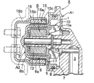
Fig. 1 is the sectional arrangement drawing of magnetic drive pump.
Fig. 2 is the sectional drawing of magnetic cup and external magnet.
Fig. 3 is the portion's enlarged view of wanting of the present invention.
Fig. 4 is the fragmentary perspective cross sectional view of magnetic cup and external magnet.
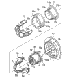
Fig. 5 is the exploded perspective view of magnetic drive pump.
Sectional drawing when Fig. 6 is the separated state of magnetic cup and external magnet.
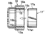
Sectional drawing when Fig. 7 is the separated state of magnetic cup and external magnet.
Fig. 8 is the portion's enlarged view of wanting of the present invention.
Embodiment
Below, referring to figs. 1 through Fig. 6 the 1st embodiment of the present invention is described.The structure of magnetic drive pump is described earlier.Pump case A mainly is made of pump case main body portion A1 and joiner wall part A2.On this pump case main body portion A1, form the blade wheel chamber 1 of circular.Be provided with impeller supporting axle 2 in the central position of this blade wheel chamber 1.In blade wheel chamber 1, forming suction port 3 (see figure 1)s and exhaust port 4 (see figure 5)s.
Blade wheel chamber's 1 relative being installed with of joiner wall part A2 and pump case main body portion A1 accommodated impeller B with blade wheel chamber 1.This joiner wall part A2, its profile roughly is the cap shape, is made of the capping portion 5 and the accommodation section cylindraceous 6 that cover above-mentioned blade wheel chamber 1, and the internal magnet 12 of impeller B can be swum and is inserted in this accommodation section 6.
Forming in the above-mentioned capping portion 5 and be housed in the circle-shaped linking department 7 in all side 1a in the blade wheel chamber 1.Form the groove 7a that can wait sealed member 8 to embed for O shape ring on this linking department 7, joiner wall part A2 be contained in pump case main body portion A1 when going up, and the pump outside between by above-mentioned sealed member 8 blade wheel chamber 1 is formed watertight and constructs.Joiner wall part A2 passes through hardly in order to make the magnetic force from aftermentioned external magnet 15 with reducing, and the most handy synthetic resin forms.
Impeller B is made of blade part 10, magnet fixing part 11, internal magnet 12 and a quilt axle parts 13.Blade part 10 is made of a plurality of blade 10a, 10a..., and blade part 10 and above-mentioned magnet fixing part 11 form as one, and accommodates fixing internal magnet 12 in magnet fixing part 11.In fact as seen, internal magnet 12 is to be housed in the magnet fixing part 11 with the state that is cast into by synthetic resin from Fig. 1.
Above-mentioned internal magnet 12 is cylindrical shapes, is axially connected the direction center, footpath of internal magnet 12 by an axle parts 13.This is propped up parts 13 by axle is tubuloses, is being propped up by 2 of impeller supporting axles by an axle parts 13, and this impeller supporting axle 2 is located in the blade wheel chamber 1 of pump case main body portion A1.Like this, as shown in Figure 1, impeller B is being supported in blade wheel chamber 1 rotationally.
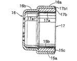
Above-mentioned assembly department 16a is different with the diameter that is driven the 16b of portion, forms step at assembly department 16a with the intersection that is driven the 16b of portion.External magnet 15 is installed on assembly department 16a, surrounds the circumferential lateral surface 15a of external magnet 15 by assembly department 16a.The portion 16b of being driven is installed on running shaft (this running shaft is located on the engine body) etc., perhaps as illustrated in fig. 1, the rotation transmission member of sprocket wheel etc. is installed.
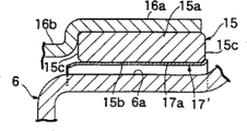
As shown in Figure 5, covering 17 is made of flange shape 17b of all side covering part 17a in cylindraceous and flange-like, and it is distolateral that flange shape 17b is formed on the axle direction one of all side covering part 17a in this.At the axle direction of interior all side covering part 17a, form the guide end 17a that diameter reduces slightly with the opposite side that is formed with above-mentioned flange shape 17b side
1(see figure 6).In addition, flange shape 17b is the circular plate that approaches, and near its periphery, forms the 17b of outer periphery portion that reduces a step by stepped part
1
Above-mentioned covering 17 covering protections the interior all side 15b and the end face portion 15c of external magnet 15, in order to suppress the minimizing of the magnetic force between external magnet 15 and the internal magnet 12, constitute with nonmagnetic metal and thin parts.Specifically, covering 17 preferably adopts the material of stainless steel and aluminum alloy etc.These materials of covering 17 usefulness are integrally formed by punch process.
Interior all side covering part 17a of this covering 17 are inserted in interior all side 15b of external magnet 15.At this moment, from above-mentioned diameter guide end 17a that reduce slightly, drawing and forming
1All sides in inserting are so insert easily.In addition, by this guide end 17a
1, the intensity of interior all side covering part 17a increases, and is not easy distortion.
The end face portion 15c of flange shape 17b and external magnet 15 connects airtight, and plays a protective role.In addition, the 17b of outer periphery portion of flange shape 17b
1Can cover between the opening end with the end face portion 15c of external magnet 15 and magnetic cup 16.
The following describes the 1st embodiment's effect.The internal magnet 12 of impeller B is housed in the interior perimembranous of the accommodation section 6 of joiner wall part A2, and under this state, impeller B is installed on the pump case A.Foreign side's side of above-mentioned accommodation section 6 is surrounded by interior all side 15b of external magnet 15, the magnetic cup 16 of supporting external magnet 15 is accepted from the rotation of motor and high speed rotating, the rotation of external magnet 15 passes to internal magnet 12 by magnetic force, these internal magnet 12 rotations, by the rotation of this internal magnet 12, impeller B rotation.
In this magnetic drive pump, the cylindric covering 17 that covers all side 15b in it is installed on external magnet 15, loosening even external magnet 15 produces, can prevent that also this external magnet 15 breaks away from magnetic cup 16, can prevent that pumping function from reducing.And, preventing that the structure of external magnet 15 disengaging magnetic cups 16 is very simple, assembling is easily.
The following describes its effect.Because the circumferential lateral surface 15a of external magnet 15 is being supported by magnetic cup 16; in addition; interior all side 15b lining cover pieces 17 of external magnet 15 are being protected with connecting airtight; so; external magnet 15 is owing to lining cover piece 17 is being protected; can be subjected to the influence of extraneous factors such as fierce temperature difference, vibration less, so can improve the durability of external magnet 15.
Therefore, even also can use in the harsh and unforgiving environments such as low temperature, high temperature, other temperature variation or vibration that in motor, wait.In addition because as long as with covering 17 with on the interior all side 15b that connect airtight shape and be installed in external magnet 15, so, construct extremely simply, it is also easy to assemble.
In addition, on covering 17, owing to form flange shape 17b of the axle direction end that covers external magnet 15, so, not only interior all side 15b of external magnet 15 are capped, and the axle direction end face 15c of external magnet 15 also can cover by flange shape 17b, external magnet 15 roughly can be covered all sidedly, can adapt to the harsh and unforgiving environments of the bigger temperature difference of generation, vibration etc.
And, because the formation of covering 17 usefulness nonmagnetic materials, so; can protect the gap of 12 of external magnet 15 in the magnetic joiner and internal magnets, reduce influence, even magnetic force lining cover piece 17 blocks magnetic force; also can farthest suppress the reduction of magnetic force, can bring into play the performance of magnetic joiner.
In addition, when above-mentioned covering 17 is formed by stainless steel,, also can guarantee enough intensity and durability even covering 17 is as thin as a wafer, and, the magnetic force of external magnet 15 is fully passed through.
In addition, when above-mentioned covering 17 was formed by thin material, interior all side covering part 17a of covering 17 and flange shape 17b can comply with the interior all side 15b and the end face portion 15c of external magnet 15 well, can become the state that connects airtight mutually, and external magnet 15 also is not easy to produce loosening.
Fig. 7 and Fig. 8 represent the present invention the 2nd embodiment, among this embodiment, do not adopt the covering 17 among above-mentioned the 1st embodiment, but adopt the covering 17 do not have flange shape 17b '.At this moment, interior all side of external magnet 15 lining cover piece 17 ' be covered with only.
The above-mentioned embodiments of the invention that illustrated, but the present invention is not limited to the foregoing description, not breaking away under the situation of the present invention that is recorded in claim, can do various design alterations.
Claims (4)
1. magnetic drive pump, the internal magnet that impeller had is housed in the cylindric accommodation section of pump case, the circumferential lateral surface of above-mentioned accommodation section is being inserted in the upstream, interior all sides of the external magnet that rotates by magnetic cup supporting and with this magnetic cup in circumferential lateral surface, rotation along with external magnet, wheel rotation, it is characterized in that, above-mentioned external magnet is made of the single member of drum, the covering cylindraceous of the interior all sides that cover above-mentioned external magnet is installed on this external magnet, this covering comprises: with interior all sides of above-mentioned external magnet install with connecting airtight cylindraceous in all side covering part and, be formed on the flange shape portion of the flange-like on axle direction one end of all side covering part in this
And axle direction of all side covering part in this is being provided with the slightly little guide end of diameter with the opposite side that is formed with above-mentioned flange shape side.
2. magnetic drive pump as claimed in claim 1 is characterized in that, above-mentioned covering adopts the stainless steel material of thin-walled integrally formed by punch process.
3. magnetic drive pump as claimed in claim 1 is characterized in that above-mentioned covering is formed by thin-walled member, and the guide end of this covering is stretch forming.
4. magnetic drive pump as claimed in claim 1 is characterized in that, near the periphery of above-mentioned flange shape portion, forms the outer periphery portion that reduces a step by stepped part.
Applications Claiming Priority (2)
| Application Number | Priority Date | Filing Date | Title |
|---|---|---|---|
| JP338393/2000 | 2000-11-06 | ||
| JP2000338393A JP3930243B2 (en) | 2000-11-06 | 2000-11-06 | Magnet pump |
Publications (2)
| Publication Number | Publication Date |
|---|---|
| CN1353251A CN1353251A (en) | 2002-06-12 |
| CN100434719C true CN100434719C (en) | 2008-11-19 |
Family
ID=18813606
Family Applications (1)
| Application Number | Title | Priority Date | Filing Date |
|---|---|---|---|
| CNB011213256A Expired - Fee Related CN100434719C (en) | 2000-11-06 | 2001-05-31 | magnetic force pump |
Country Status (7)
| Country | Link |
|---|---|
| US (1) | US6607370B2 (en) |
| JP (1) | JP3930243B2 (en) |
| CN (1) | CN100434719C (en) |
| CA (1) | CA2360401C (en) |
| ES (1) | ES2212699B1 (en) |
| IT (1) | ITTO20011020A1 (en) |
| TW (1) | TW503299B (en) |
Cited By (1)
| Publication number | Priority date | Publication date | Assignee | Title |
|---|---|---|---|---|
| CN104094508A (en) * | 2011-05-13 | 2014-10-08 | 开利公司 | Magnetic drive coupling apparatus |
Families Citing this family (36)
| Publication number | Priority date | Publication date | Assignee | Title |
|---|---|---|---|---|
| CA2417214C (en) * | 2000-08-03 | 2016-06-21 | Johns Hopkins University | Molecular vaccine linking an endoplasmic reticulum chaperone polypeptide to an antigen |
| JP3913980B2 (en) * | 2000-12-22 | 2007-05-09 | 本田技研工業株式会社 | Magnetic-type pump drive device for vehicle engine |
| US20060131887A1 (en) * | 2002-05-24 | 2006-06-22 | Gosvener Kendall C | Magnetically actuated reciprocating motor and process using reverse magnetic switching |
| JP3877211B2 (en) | 2003-03-20 | 2007-02-07 | 株式会社イワキ | Manufacturing method of rear casing in magnet pump |
| US7101158B2 (en) * | 2003-12-30 | 2006-09-05 | Wanner Engineering, Inc. | Hydraulic balancing magnetically driven centrifugal pump |
| DE102004019721A1 (en) * | 2004-03-18 | 2005-10-06 | Medos Medizintechnik Ag | pump |
| US7137793B2 (en) * | 2004-04-05 | 2006-11-21 | Peopleflo Manufacturing, Inc. | Magnetically driven gear pump |
| DE102004024554B4 (en) * | 2004-05-18 | 2018-01-25 | Pfeiffer Vacuum Gmbh | Oil-sealed rotary vane vacuum pump |
| US7500829B2 (en) * | 2005-02-04 | 2009-03-10 | Sundyne Corporation | Two piece separable impeller and inner drive for pump |
| TWI264989B (en) * | 2005-02-25 | 2006-10-21 | Delta Electronics Inc | Liquid-cooling type heat-dissipation module |
| US7183683B2 (en) * | 2005-06-23 | 2007-02-27 | Peopleflo Manufacturing Inc. | Inner magnet of a magnetic coupling |
| US7549205B2 (en) * | 2005-06-24 | 2009-06-23 | Peopleflo Manufacturing Inc. | Assembly and method for pre-stressing a magnetic coupling canister |
| TWM279743U (en) * | 2005-07-15 | 2005-11-01 | Delta Electronics Inc | Centrifugal water pump having an integral rotor |
| FR2912474B1 (en) * | 2007-02-08 | 2012-08-31 | Pierburg | WATER PUMP |
| US8786143B2 (en) | 2010-07-08 | 2014-07-22 | Kendall C. Gosvener | Magnetically actuated reciprocating motor and process using reverse magnetic switching |
| US8324763B2 (en) | 2010-07-08 | 2012-12-04 | Gosvener Kendall C | Magnetically actuated reciprocating motor and process using reverse magnetic switching |
| US8344560B2 (en) | 2010-07-08 | 2013-01-01 | Gosvener Kendall C | Magnetically actuated reciprocating motor and process using reverse magnetic switching |
| CN102465885A (en) * | 2010-11-18 | 2012-05-23 | 黄佳华 | Horizontal high-speed magnetic pump |
| EP2674624B1 (en) * | 2011-02-10 | 2019-07-03 | Nipro Corporation | Pump configuration |
| US10260507B2 (en) * | 2011-08-23 | 2019-04-16 | Moog Inc. | Magnetically coupled pump assembly |
| JP4969695B1 (en) * | 2011-09-15 | 2012-07-04 | 三菱重工業株式会社 | Drive device for magnetic coupling pump and magnetic coupling pump unit |
| BR112015005551B1 (en) | 2012-09-12 | 2021-04-13 | Fmc Technologies, Inc | SUBMERSIBLE FLUID SYSTEM TO OPERATE SUBMERSURE IN A BODY OF WATER AND RELATED METHOD |
| SG11201501910TA (en) | 2012-09-12 | 2015-04-29 | Fmc Technologies | Subsea compressor or pump with hermetically sealed electric motor and with magnetic coupling |
| CN105074223A (en) | 2012-09-12 | 2015-11-18 | Fmc技术股份有限公司 | Subsea multiphase pump or compressor with magnetic coupling and cooling or lubrication by liquid or gas extracted from process fluid |
| EP2901016B1 (en) * | 2012-09-12 | 2020-10-21 | FMC Technologies, Inc. | Coupling an electric machine and fluid-end |
| EP2971764B1 (en) | 2013-03-15 | 2019-06-12 | FMC Technologies, Inc. | Submersible well fluid system |
| DE102013008795B3 (en) * | 2013-05-24 | 2014-08-21 | Ksb Aktiengesellschaft | pump assembly |
| US9771938B2 (en) | 2014-03-11 | 2017-09-26 | Peopleflo Manufacturing, Inc. | Rotary device having a radial magnetic coupling |
| KR200478830Y1 (en) | 2014-04-21 | 2015-11-19 | 지이 일렉트리컬 엔지니어링 컴퍼니., 리미티드. | Supporting frame for a magnet pump |
| EP2960515B1 (en) * | 2014-06-24 | 2018-10-31 | Grundfos Holding A/S | Magnetic coupling |
| JP6381451B2 (en) * | 2015-01-17 | 2018-08-29 | 株式会社鷺宮製作所 | Centrifugal pump |
| US9920764B2 (en) | 2015-09-30 | 2018-03-20 | Peopleflo Manufacturing, Inc. | Pump devices |
| JP6507998B2 (en) * | 2015-11-03 | 2019-05-08 | 株式会社デンソー | Fuel pump |
| US11097236B2 (en) | 2016-03-31 | 2021-08-24 | Global Life Sciences Solutions Usa Llc | Magnetic mixers |
| US10583409B2 (en) | 2016-03-31 | 2020-03-10 | General Electric Company | Axial flux stator |
| DE102018211541A1 (en) * | 2018-07-11 | 2020-01-16 | Magna Powertrain Bad Homburg GmbH | water pump |
Citations (3)
| Publication number | Priority date | Publication date | Assignee | Title |
|---|---|---|---|---|
| CN1035709A (en) * | 1989-02-17 | 1989-09-20 | 吴加兴 | Magnetic drive pump |
| JPH0332196U (en) * | 1989-08-08 | 1991-03-28 | ||
| US5017102A (en) * | 1988-11-30 | 1991-05-21 | Hitachi, Ltd. | Magnetically coupled pump and nuclear reactor incorporating said pump |
Family Cites Families (8)
| Publication number | Priority date | Publication date | Assignee | Title |
|---|---|---|---|---|
| US2745351A (en) * | 1952-09-02 | 1956-05-15 | Hermag Pumps Ltd | Motor driven pumps |
| US3411450A (en) * | 1967-03-07 | 1968-11-19 | Little Giant Corp | Pump |
| US3545892A (en) * | 1969-07-07 | 1970-12-08 | March Mfg Co | Magnetically-coupled pump |
| DE3712459A1 (en) * | 1987-04-11 | 1988-10-27 | Klaus Union Armaturen | MAGNETIC PUMP DRIVE |
| JPH0332196A (en) | 1989-06-28 | 1991-02-12 | Matsushita Electric Ind Co Ltd | Electric device with remote controller |
| US5248245A (en) * | 1992-11-02 | 1993-09-28 | Ingersoll-Dresser Pump Company | Magnetically coupled centrifugal pump with improved casting and lubrication |
| US5779456A (en) * | 1996-10-28 | 1998-07-14 | Finish Thompson Inc. | Magnetic drive |
| US5915931A (en) * | 1997-11-13 | 1999-06-29 | The Gorman-Rupp Company | Magnetic drive unit having molded plastic magnetic driver |
-
2000
- 2000-11-06 JP JP2000338393A patent/JP3930243B2/en not_active Expired - Fee Related
-
2001
- 2001-05-31 CN CNB011213256A patent/CN100434719C/en not_active Expired - Fee Related
- 2001-10-25 IT IT2001TO001020A patent/ITTO20011020A1/en unknown
- 2001-10-25 US US09/983,772 patent/US6607370B2/en not_active Expired - Fee Related
- 2001-10-29 CA CA002360401A patent/CA2360401C/en not_active Expired - Fee Related
- 2001-10-30 ES ES200102402A patent/ES2212699B1/en not_active Expired - Fee Related
- 2001-11-01 TW TW090127140A patent/TW503299B/en not_active IP Right Cessation
Patent Citations (3)
| Publication number | Priority date | Publication date | Assignee | Title |
|---|---|---|---|---|
| US5017102A (en) * | 1988-11-30 | 1991-05-21 | Hitachi, Ltd. | Magnetically coupled pump and nuclear reactor incorporating said pump |
| CN1035709A (en) * | 1989-02-17 | 1989-09-20 | 吴加兴 | Magnetic drive pump |
| JPH0332196U (en) * | 1989-08-08 | 1991-03-28 |
Cited By (2)
| Publication number | Priority date | Publication date | Assignee | Title |
|---|---|---|---|---|
| CN104094508A (en) * | 2011-05-13 | 2014-10-08 | 开利公司 | Magnetic drive coupling apparatus |
| CN104094508B (en) * | 2011-05-13 | 2017-10-24 | 开利公司 | Magnetic driving coupling device |
Also Published As
| Publication number | Publication date |
|---|---|
| US20020054820A1 (en) | 2002-05-09 |
| US6607370B2 (en) | 2003-08-19 |
| JP3930243B2 (en) | 2007-06-13 |
| ES2212699B1 (en) | 2005-07-16 |
| CA2360401C (en) | 2005-07-26 |
| TW503299B (en) | 2002-09-21 |
| ES2212699A1 (en) | 2004-07-16 |
| ITTO20011020A1 (en) | 2003-04-25 |
| CN1353251A (en) | 2002-06-12 |
| JP2002138985A (en) | 2002-05-17 |
| CA2360401A1 (en) | 2002-05-06 |
Similar Documents
| Publication | Publication Date | Title |
|---|---|---|
| CN100434719C (en) | magnetic force pump | |
| CN208623466U (en) | Motor | |
| FR2787527B1 (en) | MOTORIZED DEVICE WITH CENTRIFUGAL FLUID CIRCULATION, SUCH AS A MOTOR PUMP OR A MOTOR COMPRESSOR | |
| US20070096575A1 (en) | Flywheel magnet rotor | |
| KR200403613Y1 (en) | power transmission shaft one body motor | |
| JP4897442B2 (en) | Fan motor drain structure | |
| EP2730785A1 (en) | Automotive electric liquid pump | |
| KR101190737B1 (en) | Electromagnetic clutch pulley | |
| JP4849328B2 (en) | Double stator type motor | |
| CN109709528B (en) | Motor, motor element and laser emission assembly | |
| JP2009281579A (en) | Electromagnetic clutch | |
| JP2021136788A (en) | Waterproof structure of motor with magnetic type encoder | |
| JP3226844U (en) | Centrifugal pump | |
| JP2551711Y2 (en) | Magnet coupling for pump | |
| JPH10201174A (en) | Structure of mounting generator to engine | |
| CN216819563U (en) | Permanent magnet steering torque motor | |
| JPH04234596A (en) | Motor-driven fuel pump | |
| EP1002943A3 (en) | Improved integrated torque motor and throttle body | |
| JP3002806U (en) | Pachinko launcher structure | |
| JPS6194298U (en) | ||
| TH50915A (en) | Magnetic driven pumps | |
| KR200168991Y1 (en) | Electric clutch for compressor | |
| JP2777658B2 (en) | Hughal pump | |
| CN105916702A (en) | Vehicle wheel structure and remote control mobile device using same | |
| TH38736B (en) | Magnetic driven pumps |
Legal Events
| Date | Code | Title | Description |
|---|---|---|---|
| C10 | Entry into substantive examination | ||
| SE01 | Entry into force of request for substantive examination | ||
| C06 | Publication | ||
| PB01 | Publication | ||
| C14 | Grant of patent or utility model | ||
| GR01 | Patent grant | ||
| C17 | Cessation of patent right | ||
| CF01 | Termination of patent right due to non-payment of annual fee |
Granted publication date: 20081119 Termination date: 20140531 |