CN100417841C - gear - Google Patents
gear Download PDFInfo
- Publication number
- CN100417841C CN100417841C CNB2005100655381A CN200510065538A CN100417841C CN 100417841 C CN100417841 C CN 100417841C CN B2005100655381 A CNB2005100655381 A CN B2005100655381A CN 200510065538 A CN200510065538 A CN 200510065538A CN 100417841 C CN100417841 C CN 100417841C
- Authority
- CN
- China
- Prior art keywords
- tooth
- gear
- sponson
- teeth
- flank
- Prior art date
- Legal status (The legal status is an assumption and is not a legal conclusion. Google has not performed a legal analysis and makes no representation as to the accuracy of the status listed.)
- Expired - Fee Related
Links
Images


Classifications
-
- F—MECHANICAL ENGINEERING; LIGHTING; HEATING; WEAPONS; BLASTING
- F16—ENGINEERING ELEMENTS AND UNITS; GENERAL MEASURES FOR PRODUCING AND MAINTAINING EFFECTIVE FUNCTIONING OF MACHINES OR INSTALLATIONS; THERMAL INSULATION IN GENERAL
- F16H—GEARING
- F16H55/00—Elements with teeth or friction surfaces for conveying motion; Worms, pulleys or sheaves for gearing mechanisms
- F16H55/02—Toothed members; Worms
- F16H55/14—Construction providing resilience or vibration-damping
- F16H55/16—Construction providing resilience or vibration-damping relating to teeth only
-
- Y—GENERAL TAGGING OF NEW TECHNOLOGICAL DEVELOPMENTS; GENERAL TAGGING OF CROSS-SECTIONAL TECHNOLOGIES SPANNING OVER SEVERAL SECTIONS OF THE IPC; TECHNICAL SUBJECTS COVERED BY FORMER USPC CROSS-REFERENCE ART COLLECTIONS [XRACs] AND DIGESTS
- Y10—TECHNICAL SUBJECTS COVERED BY FORMER USPC
- Y10T—TECHNICAL SUBJECTS COVERED BY FORMER US CLASSIFICATION
- Y10T74/00—Machine element or mechanism
- Y10T74/19—Gearing
- Y10T74/1987—Rotary bodies
- Y10T74/19893—Sectional
- Y10T74/19898—Backlash take-up
Landscapes
- Engineering & Computer Science (AREA)
- General Engineering & Computer Science (AREA)
- Mechanical Engineering (AREA)
- Gears, Cams (AREA)
Abstract
一种外圆周表面具有齿2的齿轮,齿2中的每个齿都具有一个可弹性变形的外伸部分7,该外伸部分形成在齿2的一个相应齿的齿宽方向的一个端面6上,使其从齿2的一个相应齿的一个齿面8附近的一个部分向齿2的一个相邻齿突出,并且与配对齿轮的齿中的一个齿相接触的外伸部分7的一个部分是这样形成的,即,当外伸部分7被配对齿轮的齿中的一个齿压住并产生弹性变形时,具有和齿面8中的一个齿面相同的平面。
A gear having teeth 2 on the outer peripheral surface, each of the teeth 2 having an elastically deformable overhang 7 formed on an end face 6 of a corresponding one of the teeth 2 in the tooth width direction a portion of the overhanging portion 7 that protrudes from a portion near a tooth face 8 of a corresponding one of the tooth 2 toward an adjacent tooth of the tooth 2 and that is in contact with one of the teeth of the mating gear It is formed so that the overhanging portion 7 has the same plane as one of the tooth surfaces 8 when it is pressed by one of the teeth of the mating gear and elastically deformed.
Description
技术领域 technical field
本发明涉及一种可以在旋转传递过程中减少噪音和振动的齿轮。The present invention relates to a gear that can reduce noise and vibration during rotation transmission.
背景技术 Background technique
近些年来,例如一种在办公桌上使用的典型喷墨打印机打印部分的驱动机构和进纸机构中都使用很多齿轮来将马达的转动通过这些齿轮传递给从动部件。在这种喷墨打印机中,打印部分的驱动机构和进纸机构被设计为频繁地反复转动与停止,因此会出现这样一些情况,即,在停止和起动的过程中,一对相互啮合的齿轮中的一个齿轮由于惯性可能会碰撞到另外一个齿轮,从而产生齿敲击噪音以及由于振动等所产生的噪音。然而,为了提供良好的办公环境,上述在办公桌上使用的喷墨打印机需要减小运转噪音以使得运转尽可能的安静。因此,人们已经设计出各种各样的齿轮来减少动力传输过程中的运转噪音。In recent years, for example, many gears are used in the driving mechanism and the paper feeding mechanism of a typical inkjet printer used on a desk to transmit the rotation of the motor to the driven parts through these gears. In this inkjet printer, the driving mechanism of the printing part and the paper feeding mechanism are designed to rotate and stop frequently and repeatedly, so there will be such situations that a pair of gears meshing with each other will One of the gears may collide with another gear due to inertia, resulting in tooth knocking noise and noise due to vibration and so on. However, in order to provide a good office environment, the above-mentioned inkjet printers used on desks need to reduce the running noise so as to run as quietly as possible. Therefore, various gears have been devised to reduce running noise during power transmission.
图13A和13B中所显示的齿轮50可作为第一传统实施例,该齿轮具有突片部分52,其形成在每个齿51齿宽方向上的一个端部的两个齿面上,当齿轮50和配对齿轮相啮合时,该突片部分可以与和齿轮50相啮合的配对齿轮相接触并产生变形以减震(参见公开号为55-100745的待审日本实用新型)。A
图14A和14B中所显示的齿轮53可作为第二传统实施例,该齿轮具有狭缝56,该狭缝形成于与配对齿轮54相啮合的齿面55的一侧,该狭缝沿齿面55延伸并在齿宽方向上贯穿齿面,每个狭缝都使得当齿面55与配对齿轮54相啮合时,与配对齿轮54相啮合的齿面55可以弹性地变形以减震(参见公开号为58-127246的待审日本实用新型)。The
图15中所显示的齿轮57可作为第三传统实施例,该齿轮具有通孔60,该通孔在齿宽方向上贯穿齿面58,该通孔使得当齿轮57与配对齿轮相啮合时,整个齿58能够容易地弹性变形以减震(参见公开号为55-98849的待审日本实用新型)。The
图16中所显示的齿轮61可作为第四传统实施例,该齿轮具有狭缝63,该狭缝在每个齿62上形成,在齿宽方向上延伸跨越整个齿宽并从齿顶64延伸穿过齿根面65,该狭缝使得当齿轮61与配对齿轮相啮合时,齿62能够容易地弹性变形以减震(参见公开号为55-98850的日本实用新型)。As a fourth conventional embodiment, a
图17中所显示的齿轮66可作为第五传统实施例,该齿轮具有粘弹性体70,该粘弹性体从每个齿67的两个齿面68的齿宽方向的中央部分突出,当齿轮66与配对齿轮相啮合时,每个粘弹性体都可以与配对齿轮的一个齿面相接触以减震(参见公开号为2001-221322的待审日本专利)。A gear 66 shown in FIG. 17 can be used as a fifth conventional embodiment, and the gear has a
在图18中所显示的、由本申请的发明人所提出的齿轮71可作为第六传统实施例,该齿轮具有腔室部分73,该腔室部分形成于齿72的齿宽方向上的两个端部,在齿宽方向上具有腔室部分73的两个端部74和其它部分之间注模之后,由于收缩的不同在齿宽方向上的两个端部形成了可弹性变形的膨胀部分74,当齿轮71与配对齿轮相啮合时,该可弹性变形的膨胀部分74可以弹性地变形以减震(参见公开号为2003-90412的待审日本专利)。A
然而,在第一传统实施例中,该突片部分52只形成于齿宽方向的一个端部上,在该突片部分上也不具备有吸收变形能力的薄壁部分和空腔部分,因此,施加于突片部分52上的表面压力过大以致于突片部分52容易磨损。因此,当齿轮与配对齿轮相啮合时,就会出现该突片部分52不可能获得长时间减震效果,所以,突片部分52也不可能稳定地获得长时间齿敲击噪音的吸纳效果。However, in the first conventional embodiment, the
在第二传统实施例中,由于在动力传输过程中与配对齿轮相啮合的齿面55在齿宽方向上的整个区域都可以弹性变形,弹性变形量随动力传输过程中负载的不同而变化,因此,每个齿的旋转角度很容易改变。所以,齿轮53很难应用于需要精确地传递转动的齿轮系中。In the second conventional embodiment, since the entire area in the tooth width direction of the
在第三和第四传统实施例中,由于整个齿58和62都可以轻易地变形,与第二传统实施例中的情况类似,齿58和62的弹性变形量随动力传输过程中负载的不同而变化,因此,每个齿的旋转角度很容易改变。所以,齿轮57和61很难应用于需要精确地传递转动的齿轮系中。In the third and fourth conventional embodiments, since the
在第五传统实施例中,尽管从齿面68突出的粘弹性体70在动力传输过程中被负载所压缩而产生变形,但是,弹性变形量随动力传输过程中负载的不同而变化。因此,与第二到第四传统实施例相似,齿轮66很难应用于需要精确地传递转动的齿轮系中。In the fifth conventional embodiment, although the
在第六传统实施例中,如果膨胀部分74弹性变形的话,那么,除了膨胀部分74以外的齿面75与配对齿轮的齿面相接触以传递动力。因此,它可能比第二到第五传统实施例中的齿轮更精确地传递转动。除此以外,由于膨胀部分74形成于齿宽方向的两个端部上,当齿轮71与配对齿轮相啮合时,它很可能使表面压力降低,而不像第一传统实施例中的齿轮那样容易造成齿72的早期磨损。然而,由于膨胀部分74是在注模后收缩不同的基础上形成的,膨胀量很小,所以膨胀部分74不可能从齿面75上非常突出,因此也不可能充分地减震。In the sixth conventional embodiment, if the
本申请的发明人已经提出一个图19中所示的齿轮81,该齿轮可以消除第一到第六传统实施例中的问题,该齿轮具有可弹性变形的外伸部分84,该外伸部分从每个齿82的齿面83中的一个齿面向一个相邻齿82的方向突出以吸收间隙,从而减小齿间的敲击噪音和振动噪音(申请号为2004-22765的日本专利)。The inventors of the present application have proposed a
相对于第一至第六传统实施例中齿轮,当齿轮81与配对齿轮向啮合时,齿轮81可以通过啮合间隙来减小齿敲击噪音,还可以减小用于反复旋转和停止的间歇转动传递机构中的运转噪音。然而,许多使用齿轮81的喷墨打印机为了清洁都设计为可以反向旋转打印部分的驱动轴,因此,就需要减小反向转动过程中的运转噪音。Compared with the gears in the first to sixth conventional embodiments, when the
发明内容 Contents of the invention
本发明的一个目的就是提供一种齿轮,使其在消除上述第一到第六传统实施例中存在的问题的同时,也可以减小反向转动过程中的运转噪音。An object of the present invention is to provide a gear which can reduce running noise during reverse rotation while eliminating the problems of the first to sixth conventional embodiments described above.
为了实现上述和其它的一些目的,本发明提供了一种在外圆周表面上有齿的齿轮,每个齿都具有可弹性变形的外伸部分,该外伸部分位于一个齿的齿宽方向上的至少一个端面上,从临近该相应齿的一个齿面的部分向相邻齿的方向突出,与配对齿轮的齿中的一个齿相接触的所述外伸部分的一个部分是这样形成的,即,当所述外伸部分被所述配对齿轮的齿中的一个齿压住产生弹性变形时,具有和齿面中的一个齿面相同的平面。In order to achieve the above and other objects, the present invention provides a gear with teeth on the outer peripheral surface, each tooth has an elastically deformable overhanging portion located at a tooth width direction of a tooth. At least one end face, protruding from a portion of a tooth surface adjacent to the corresponding tooth in the direction of the adjacent tooth, a portion of said overhang that contacts one of the teeth of the mating gear is formed such that , when the overhanging portion is elastically deformed by being pressed by one of the teeth of the mating gear, it has the same plane as one of the tooth surfaces.
在该齿轮中,外伸部分可以是一个基本为板状的突出片,外伸部分可以具有一个设置在一个端面上的根部以便其从一个齿面缩回,外伸部分基本上沿着一个齿面延伸,外伸部分径向上的一个内侧端部设置在相应齿径向上的齿根面内侧。外伸部分的内侧端部可以连接到形成在一个端面上的环形凸出部上。外伸部分径向上的外侧端部可以这样设置从而使其位于从齿顶向齿根面的一段预定距离处。该外伸部分可以以其径向上的外侧端部从根部向顶部倾斜的方式形成。In the gear, the overhanging portion may be a substantially plate-shaped protruding piece, the overhanging portion may have a root provided on an end face so that it retracts from a tooth flank, the overhanging portion is substantially along a tooth The radially inner end of the overhanging part is arranged on the inner side of the tooth root surface in the corresponding tooth radial direction. The inner end of the overhanging portion may be connected to an annular protrusion formed on one end face. The radially outer end portion of the overhanging portion may be arranged so as to be located at a predetermined distance from the tooth top to the tooth root surface. The overhang portion may be formed in such a manner that its radially outer end portion is inclined from the root to the top.
如果本发明的齿轮被用于可以反复旋转和停止的齿轮系,当一对相互啮合的齿轮以齿间隙移动而彼此接触时,一个齿轮的外伸部分弹性地和与其相啮合配对齿轮的一个相应齿的齿面相接触,从而实现减震功能,因此,使得抑制齿敲击噪音和振动噪音的产生成为可能。根据本发明的齿轮的外伸部分可以是一个基本为板状的突出片,该外伸部分的根部可以形成于齿宽方向的端面上以便从齿面缩回。此外,在旋转的传递过程中,与配对齿轮的一个相应齿相接触的外伸部分可以与配对齿轮具有相同的平面。从而施加于外伸部分上的接触压力不会过大,使得在反向旋转的传递过程中减小运转噪音成为可能。If the gear of the present invention is used in a gear train that can repeatedly rotate and stop, when a pair of gears meshing with each other moves with backlash to contact each other, the protruding portion of one gear elastically contacts a corresponding one of the mating gear that meshes with it. The tooth surfaces of the teeth are in contact, thereby realizing a shock absorbing function, thus making it possible to suppress generation of tooth knocking noise and vibration noise. The overhanging portion of the gear according to the present invention may be a substantially plate-shaped protruding piece, and the root of the overhanging portion may be formed on the end surface in the tooth width direction so as to be retracted from the tooth surface. Furthermore, the overhang which contacts a corresponding tooth of the mating gear during transmission of rotation may have the same plane as the mating gear. The contact pressure exerted on the overhanging portion is thus not too great, making it possible to reduce running noise during the transfer of the counter-rotation.
附图说明 Description of drawings
从下面的具体描述和本发明优选实施例的附图可以更好地理解本发明。然而,附图不是将发明限制于某个特定的实施例,而只是用于解释和理解发明之用。The present invention can be better understood from the following detailed description and accompanying drawings of preferred embodiments of the invention. However, the drawings are not intended to limit the invention to a specific embodiment, but are merely for explaining and understanding the invention.
图中:In the picture:
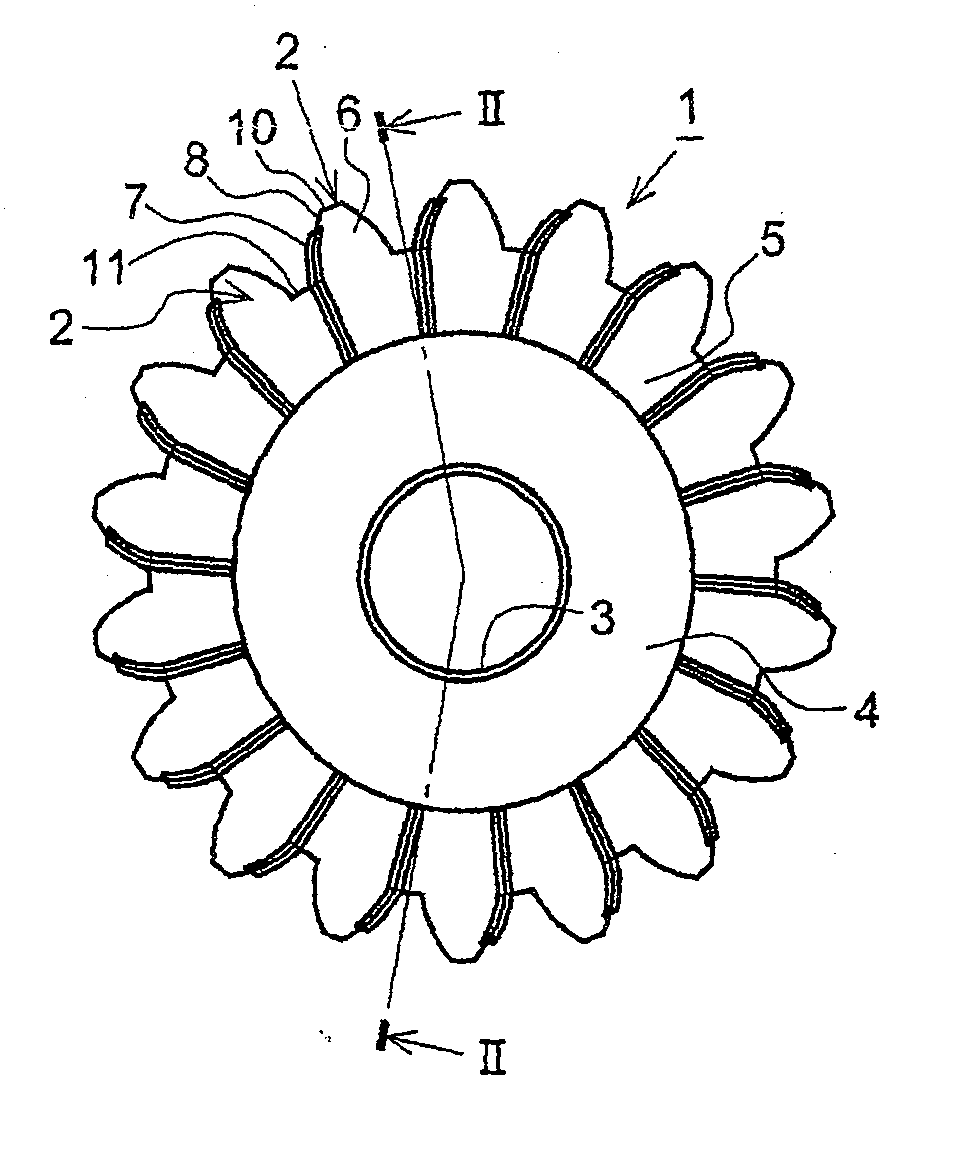
图1为根据本发明的齿轮的第一优选实施例的前视图;Figure 1 is a front view of a first preferred embodiment of a gear according to the invention;
图2为沿图1中的线II-II的剖视图;Fig. 2 is a sectional view along the line II-II in Fig. 1;
图3为沿图2中的箭头A的方向所显示的图1中齿轮的一个齿的平面图;Fig. 3 is a plan view of a tooth of the gear in Fig. 1 shown along the direction of arrow A among Fig. 2;
图4A为图1中齿轮的一部分的放大的前视图;Figure 4A is an enlarged front view of a portion of the gear in Figure 1;
图4B为沿图4A中的线IVB-IVB的剖视图;Figure 4B is a cross-sectional view along line IVB-IVB in Figure 4A;
图4C为沿图4A中的线IVC-IVC的剖视图;Figure 4C is a sectional view along the line IVC-IVC in Figure 4A;
图5为喷墨打印机打印部分的驱动机构中使用本优选实施例中齿轮时的噪音值与喷墨打印机打印部分的驱动机构中使用传统齿轮时噪音值相比较的图表;Fig. 5 is a chart comparing the noise value when using the gear in the present preferred embodiment in the driving mechanism of the printing part of the inkjet printer with the noise value when using the traditional gear in the driving mechanism of the printing part of the inkjet printer;
图6为以数值形式显示的图5中噪音值的表格;Fig. 6 is the table of the noise value in Fig. 5 shown in numerical form;
图7A至图7D为显示根据本发明的齿轮的第二优选实施例的齿的平面图,其显示了图3中所示齿的改进例;7A to 7D are plan views showing teeth of a second preferred embodiment of a gear according to the present invention, which show modifications of the teeth shown in FIG. 3;
图8为根据本发明的齿轮的第三优选实施例的前视图;Figure 8 is a front view of a third preferred embodiment of a gear according to the present invention;
图9为沿图8中的线IX-IX的剖视图;Fig. 9 is a sectional view along line IX-IX in Fig. 8;
图10A为根据本发明的齿轮的第四优选实施例的一部分的放大前视图;Figure 10A is an enlarged front view of a portion of a fourth preferred embodiment of a gear according to the present invention;
图10B为沿图10A中的线XB-XB的剖视图;Figure 10B is a cross-sectional view along line XB-XB in Figure 10A;
图10C为沿图10A中的线XC-XC的剖视图;Figure 10C is a cross-sectional view along line XC-XC in Figure 10A;
图11A为根据本发明的齿轮的第五优选实施例的一部分的放大前视图;Figure 11A is an enlarged front view of a portion of a fifth preferred embodiment of a gear according to the present invention;
图11B为沿图11A中的线XIB-XIB的剖视图;Fig. 11B is a cross-sectional view along line XIB-XIB in Fig. 11A;
图11C为沿图11A中的线XIC-XIC的剖视图;Figure 11C is a cross-sectional view along line XIC-XIC in Figure 11A;
图12A为根据本发明的齿轮的第六优选实施例的一部分的放大前视图;Figure 12A is an enlarged front view of a portion of a sixth preferred embodiment of a gear according to the present invention;
图12B为沿图12A中的线XIIB-XIIB的剖视图;Figure 12B is a cross-sectional view along line XIIB-XIIB in Figure 12A;
图12C为沿图12A中的线XIIC-XIIC的剖视图;Figure 12C is a cross-sectional view along line XIIC-XIIC in Figure 12A;
图13A为传统齿轮的第一实施例的放大透视图;13A is an enlarged perspective view of a first embodiment of a conventional gear;
图13B为图13A中的齿轮的齿的放大透视图;Figure 13B is an enlarged perspective view of the teeth of the gear in Figure 13A;
图14A为传统齿轮的第二实施例的齿的放大透视图;14A is an enlarged perspective view of teeth of a second embodiment of a conventional gear;
图14B为显示图14A中的齿轮与另一个齿轮相啮合的状态的视图;FIG. 14B is a view showing a state where the gear in FIG. 14A is meshed with another gear;
图15为传统齿轮的第三实施例的齿的放大透视图;15 is an enlarged perspective view of teeth of a third embodiment of a conventional gear;
图16为传统齿轮的第四实施例的齿的放大透视图;16 is an enlarged perspective view of teeth of a fourth embodiment of a conventional gear;
图17为传统齿轮的第五实施例的齿的放大透视图;17 is an enlarged perspective view of teeth of a fifth embodiment of a conventional gear;
图18为传统齿轮的第六实施例的齿的放大透视图;18 is an enlarged perspective view of teeth of a sixth embodiment of a conventional gear;
图19为由本申请的发明人提出的为了消除第一到第六实施例中的问题的一种齿轮的齿的放大透视图;19 is an enlarged perspective view of teeth of a gear proposed by the inventors of the present application in order to eliminate the problems in the first to sixth embodiments;
具体实施方式 Detailed ways
下文将参照附图具体描述本发明的优选实施例。Hereinafter, preferred embodiments of the present invention will be described in detail with reference to the accompanying drawings.
[第一优选实施例][First preferred embodiment]
图1至图3以及图4A至图4C显示了根据本发明的一个齿轮1的第一优选实施例。图1是本优选实施例中齿轮1的前视图,图2是沿图1中线II-II的剖视图,图3是沿图2中箭头A的方向所显示的齿轮1的齿2的平面图,图4A至4C为齿2的一部分的放大视图。Figures 1 to 3 and Figures 4A to 4C show a first preferred embodiment of a
在这些图中,例如本优选实施例的齿轮1为一个直齿轮,其通过对树脂材料,如聚乙醛、聚酰胺、聚苯硫、聚对苯二甲酸丁二酯等进行注模形成。齿轮1在一个基本为盘状的板5的外圆周上具有多个齿2,该板位于具有一个轴向孔3的凸出部4的外圆周上。在本优选实施例中,每个齿2都为高齿,其具有比全齿高齿更大的啮合系数。In these figures, for example, the
齿轮1如此制造使得薄外伸部分7从每个齿2的一个端面6向外突出,另外,凸出部4从腹板5(图2中为左侧)的侧面突出并位于每个齿2在齿宽方向上的一个端面6上。外伸部分7为可弹性变形的板状突出片。外伸部分7的根部(外伸部分7与每个齿2的一个端面6的连接部分)形成于从齿面8缩回tmm(例如,0≤t≤0.1)的一个部分上。因此,如果与齿轮1相啮合的配对齿轮的齿使外伸部分7产生弹性变形,与啮合配对齿轮的齿相接触的外伸部分的接触部分很容易地被移动到与齿面8具有相同的平面。因此,啮合配对齿轮与外伸部分7之间的噪音,如摩擦噪音,就不会产生,而齿轮也可以确保相互接触。The
在齿顶10一侧设置外伸部分7的端部(上端部),使得其从齿顶10向齿底面11缩回(隔开)一段预定长度,外伸部分7如此制造使其基本沿着齿面8延伸。因此,如果齿轮1为从动轮,当齿2与配对齿轮开始啮合时,外伸部分7可以与配对齿轮平稳地接触。如果齿轮1为主动轮,当齿2从配对齿轮上分离时,外伸部分7可以从配对齿轮上平稳地分离。The end (upper end) of the overhanging
外伸部分7径向上的内端与径向设置在齿底面11内侧的凸出部(环形凸出部分)4的外圆周表面相接触。因此,注模过程中熔化的树脂的流动得到改善,使得外伸部分7可以精确地浇铸成型。从而可以有效地避免由于外伸部分7形状缺陷所造成的减震功能的减弱和由于减震功能减弱所引起的噪音的产生。The radially inner end of the overhanging
外伸部分7倾斜地形成,由于从根部7a到顶部7b的距离增加,该外伸部分接近紧邻的一个齿2,并且外伸部分7如此形成使得顶端7b确实从一个齿面8向齿2中紧邻的一个齿突出。这样,当齿轮1与配对齿轮开始啮合时,外伸部分7从顶部7b开始与配对齿轮逐渐接触并逐渐地产生弹性变形阻力。所以,齿2中的每一个都可以与配对齿轮平稳地啮合而不会产生突变力。从而可以避免在齿2中每个齿与配对齿轮啮合过程中由于撞击产生的敲击噪音和震动噪音。The overhanging
为了帮助更好地理解外伸部分7的形状,在下文将举例说明该外伸部分7的尺寸。如果齿轮的模数为大约0.5到2.0mm,外伸部分7的厚度大约为0.1mm。外伸部分7从齿宽方向上一个端面6突出的尺寸La为0.5mm,从一个齿面8突出的外伸部分7的突出尺寸等于或者小于齿间隙尺寸(参照图3和图4A至4C)。在转动的传递过程中,外伸部分7被与齿轮1相啮合的配对齿轮的一个齿接触而产生弹性变形,从而达到了使齿2中的一个相应齿平稳地接触配对齿轮的一个齿的减震功能。在本优选实施例中,如果外伸部分7可以实现减震功能的话,就不必总是要求外伸部分7能够消除齿间隙。外伸部分7的尺寸举例只是一个例子而已,本发明不应局限于此。最佳的尺寸可以根据齿2的模数和传递扭矩等条件来确定。In order to help better understand the shape of the overhanging
本优选实施例是齿轮1通过注模制造的实施例,因此外伸部分7等具有斜度。因此,尽管外伸部分7具有基本固定的厚度,但是,随着从根部7a到顶部7b距离的增加,斜度使该外伸部分7的厚度微微降低。This preferred embodiment is an embodiment in which the
图5显示了传统齿轮用于喷墨打印机的打印部分的驱动机构时所产生的噪音值与本优选实施例中齿轮用于喷墨打印机的打印部分的驱动机构时所产生的噪音值的比较。图6是一个以数值形式表示图5中噪音值的图表。Fig. 5 shows the comparison of the noise value generated when the conventional gear is used in the driving mechanism of the printing part of the inkjet printer and the noise value generated when the gear is used in the driving mechanism of the printing part of the inkjet printer in this preferred embodiment. FIG. 6 is a graph representing the noise values in FIG. 5 in numerical form.
在图5和图6中,对比例1中的齿轮是一个典型的具有全齿高的黄铜齿轮,其通常被用于和设计为与一个树脂齿轮相啮合。对比例2中的齿轮是一个高齿的树脂齿轮,其被用来代替对比例1中的黄铜齿轮。根据本发明的齿轮是本优选实施例中的齿轮1,它被用于代替对比例中的黄铜齿轮。此外,就对比例2中齿轮和本发明的齿轮1来说,一种情况(在图5和6中以MAX表示)为相互啮合的一对齿轮的中心距离是所允许的最大值,另一个情况(在图5和6中以MIN表示)为中心距离为所允许的最小值。In FIGS. 5 and 6, the gear in Comparative Example 1 is a typical brass gear with full tooth height, which is generally used and designed to mesh with a resin gear. The gear in Comparative Example 2 was a high-tooth resin gear, which was used instead of the brass gear in Comparative Example 1. The gear according to the present invention is the
如这些图中所示,在与对比例1相比较的对比例2和本发明中,其可以在“开始”、“清洁”打印模式,“标准”打印模式和“快速”打印模式的所有情况下都减小噪音值。此外,在与对比例2中MAX情况相对比的本发明的MAX的情况中,其可以减小“开始”、“清洁”打印模式,“标准”打印模式和“快速”打印模式的所有情况下的噪音值。而且,在与对比例2中MIN情况相对比的本发明的MIN的情况中,其可以减小“开始”、“清洁”打印模式,“标准”打印模式和“快速”打印模式的所有情况下的噪音值。As shown in these figures, in Comparative Example 2 compared with Comparative Example 1 and the present invention, it can be used in all cases of "Start", "Clean" printing mode, "Standard" printing mode and "Quick" printing mode Lower the noise value. In addition, in the case of MAX of the present invention compared with the case of MAX in Comparative Example 2, it can reduce the "Start", "Clean" printing mode, "Standard" printing mode and "Quick" printing mode in all cases noise value. Also, in the case of MIN of the present invention compared with the case of MIN in Comparative Example 2, it can reduce all cases of "Start", "Clean" printing mode, "Standard" printing mode and "Quick" printing mode noise value.
更进一步,根据本发明,噪音值可以比对比例1的噪音值降低5到8.4分贝(dB)。此外,根据本发明,在MAX的情况中,可以比对比例2的MAX情况中的噪音值降低0.05到2.82(dB)。而且,根据本发明,在MIN的情况中,可以比对比例2的MIN情况中的噪音值降低0.8到1.9(dB)。根据与对比例2相比较的本发明,其可以减小正转过程中的任何一种“清洁”、“标准”和“快速”模式中的噪音。根据本发明,即使是在启动运转过程中齿轮反转清洁打印部分时所产生的噪音值也基本上等于对比例2中的噪音值。根据本发明,在最大和最小中心距离(MAX和MIN)之间的噪音值的变化量小于对比例2中的相应变化量。Furthermore, according to the present invention, the noise value can be reduced by 5 to 8.4 decibels (dB) compared with the noise value of Comparative Example 1. Furthermore, according to the present invention, in the case of MAX, it is possible to reduce the noise value by 0.05 to 2.82 (dB) from the noise value in the case of MAX of Comparative Example 2. Also, according to the present invention, in the case of MIN, it is possible to reduce the noise value by 0.8 to 1.9 (dB) than in the case of MIN of Comparative Example 2. According to the present invention compared with Comparative Example 2, it is possible to reduce noise in any one of "clean", "standard" and "fast" modes during forward rotation. According to the present invention, the noise value generated even when the gear was reversed to clean the printing portion during the start-up operation was substantially equal to that in Comparative Example 2. According to the present invention, the amount of change in the noise value between the maximum and minimum center distances (MAX and MIN) is smaller than that in Comparative Example 2.
如上所述,根据本优选实施例中的齿轮1,在旋转传递过程中,外伸部分7可以被啮合配对齿轮的齿中的一个齿压缩、缩小从而发生弹性变形以抑制齿轮相互啮合时的撞击,使得抑制齿敲击噪音和振动的产生以减小运转噪音成为可能。As described above, according to the
在本优选实施例的齿轮1中,外伸部分7为板形的突出片,其可以很容易地发生弹性变形并且避免外伸部分7与配对齿轮的齿面之间的接触压力过大。因此,外伸部分7具有长时间内稳定的减震功能,从而使得在长时间内减小运转噪音以消除第一传统实施例中的问题成为可能。In the
在本优选实施例的齿轮1中,可弹性变形的外伸部分7以从每个齿2的一个端面6上突出的方式形成,并且其被设计为在旋转传递过程中可以被弹性地变形以与相应的一个齿2的齿面8具有相同的平面。因此,通过刚性齿的齿面彼此接触使精确地传递旋转成为可能,从而使得消除第二到第五传统实施例中存在的问题成为可能。In the
在本优选实施例的齿轮1中,外伸部分7从齿宽方向上的一个端面6向紧邻的一个齿2中充分突出。因此,当啮合配对齿轮的齿以齿间隙移动时,可弹性变形的外伸部分7能够实现减震功能,使得消除齿2彼此接触时的撞击成为可能。因此,在本优选实施例的齿轮1中,外伸部分7从齿面8中的一个齿面突出的突出量可以大于第六传统实施例中每个齿72的齿面75上的由于注模后收缩不同而造成的膨胀部分的尺寸,使得其可以更有效地实现减震功能。In the
在本优选实施例的齿轮1中,每个外伸部分7均为板状的突出片,外伸部分7可各自独立地弹性变形。因此,啮合配对齿轮与外伸部分7之间的接触压力可以比齿轮81中的接触压力更平稳地变化,在齿轮81中,每个外伸部分84是沿着齿面83连续形成的,使得其与紧邻的一个齿82的外伸部分84彼此连接(参照图19)。因此,特别是在一个设计有在开始运转阶段通过反向转动打印部分的驱动机构来清洁打印头的喷墨打印机中,本优选实施例中的齿轮1与齿轮81相比可以降低开始运转阶段的运转噪音(大约2dB),使得更大程度地减小运转噪音成为可能。此外,本优选实施例中的齿轮1的外伸部分7如此制造使得即使相互啮合的两个齿轮的中心距离在允许的范围内变化时也能够实现良好的减震功能。因此,相对于齿轮81来说,其可以更有效地避免由于外伸部分7与配对齿轮间过大的接触压力而引起的如摩擦噪音等噪音的产生。In the
尽管通过注模制成的树脂齿轮已经作为一个实施例在上述的优选实施例中进行了描述,但是本发明不是仅限于此,本发明可以应用于使用模具通过热/压成型的树脂齿轮和通过切削加工制成的树脂齿轮。而且,本优选实施例可以应用于一个金属齿轮。Although a resin gear formed by injection molding has been described as an example in the above-mentioned preferred embodiments, the present invention is not limited thereto, and the present invention can be applied to resin gears molded by heat/press using a mold and by Resin gears made by machining. Also, the present preferred embodiment can be applied to a metal gear.
[第二优选实施例][Second preferred embodiment]
图7A至图7D为根据本发明第二优选实施例的齿轮的齿2中的一个齿的平面视图,其显示了在上述第一优选实施例中的齿2的一个齿的改进例。在图7A中,一对外伸部分7形成于每个齿2的齿宽方向上的两个端面6和12上,使得其从靠近齿面8的一部分向紧邻的齿2中的一个齿(在图中朝向左侧)倾斜地突出。在图7B中,一对外伸部分7形成于每个齿2的齿宽方向上的两个端面6和12上,外伸部分7中的一个如此制造使得其从端面6向图中的左侧倾斜地突出,而外伸部分7中的另一个如此制造使得其从端面12向图中的右侧倾斜地突出。在图7C中,一对外伸部分7形成于齿宽方向上的一个端面6上,外伸部分7中的一个如此制造使得其从端面6向图中的左侧倾斜地突出,而外伸部分7中的另一个如此制造使得其从端面6向图中的右侧倾斜地突出。在图7D中,一对外伸部分7以与图7C中的形成于一个端面6上的那对外伸部分7相同的方式形成于另一个端面12上。然而,外伸部分7不会局限于图3所示的实施例,外伸部分7的位置和数量可以根据齿轮1的形状以及与齿轮1相啮合的配对齿轮的形状等做适当地改变。7A to 7D are plan views of one of the
[第三优选实施例][Third preferred embodiment]
图8和9显示了根据本发明的齿轮的第三优选实施例。本优选实施例可以应用于一个具有大外径的齿轮1,并且适于应用于凸出部分4和齿2之间的径向距离大的情况。也就是说,在本优选实施例中,一个圆周凸起(环形凸起)13形成在凸起部分4和齿2之间的腹板5的一个侧面上,使得其与齿2的节圆基本同心,并且外伸部分7在径向上的内端与圆周凸起13的外圆周表面相连接。根据本实施例,其也可以获得与上面第一优选实施例中所描述的齿轮1相同的有益效果。Figures 8 and 9 show a third preferred embodiment of the gear according to the invention. This preferred embodiment can be applied to a
[第四优选实施例][Fourth preferred embodiment]
图10A至图10C部分地显示了根据本发明第四优选实施例的齿轮1的齿2,其显示了上述第一优选实施例中的齿轮1的一个改进例。10A to 10C partially show the
如图10A至10C中所示,一个比已有斜度更倾斜的引导部分14如此形成,以便其从根部7a向顶部7b被倾斜地切断。因此,当本优选实施例中的齿轮1与一个配对齿轮相啮合时,配对齿轮上的一个相应齿沿着外伸部分7的引导部分14被平稳地引导至一个预定啮合位置。所以,当本优选实施例中的齿轮1与配对齿轮相啮合时,外伸部分7不会被配对齿轮的齿所破坏。As shown in FIGS. 10A to 10C, a
[第五优选实施例][Fifth Preferred Embodiment]
图11A至11C部分地显示了根据本发明第五优选实施例的齿轮1的齿2,其显示了上述第一优选实施例中的齿轮1的另一个改进例。11A to 11C partially show the
如图11A至11C中所示,在本优选实施例的齿轮1中,一个引导部分15如此形成使得外伸部分7的外端部在径向上从齿顶10向齿根面11逐渐弯曲,随着从齿顶10向齿根面11的距离增加,其中从齿面8向相邻的一个齿2突出的引导部分15的突出量以圆弧的形式逐渐增加。因此,本实施例中齿轮1的引导部分15与上述第四优选实施例中齿轮1的引导部分14具有相同的功能,从而可以获得与第四实施例中一样的有益效果。As shown in FIGS. 11A to 11C, in the
[第六优选实施例][Sixth preferred embodiment]
图12A至12C部分地显示了根据本发明第六优选实施例的齿轮1的齿2,其显示了上述第一优选实施例中的齿轮1的另一个改进例。12A to 12C partially show the
如图12A至12C中所显示的本优选实施例的齿轮1中,如图1中所示的每个外伸部分7在径向上的内侧部分从齿轮1上被切掉以减小外伸部分7的长度,每个外伸部分7在径向上的内侧端部与如图1中所示的凸出部4的外圆周表面有间隔。因此,本优选实施例中齿轮1的外伸部分7比图1中齿轮1的外伸部分更易产生弹性变形。然而,由于本优选实施例的齿轮1的每个外伸部分7在径向上的内侧端部不连接在凸出部4的外圆周表面上,在浇铸过程中外伸部分7处的树脂的流动性不是很好,所以外伸部分7的形状的精确性受到轻微地损坏。因此,需要根据操作条件适当地选择图1中的一个齿轮和本优选实施例中的一个齿轮以最优地减小运转噪音。In the
在本优选实施例的齿轮1中,由于每个外伸部分7在径向上的内侧端部被设置在齿根面11径向的内侧,因此,即使任何一个外伸部分7的内侧端部径向上的形状存在缺陷和/或即使在注模过程中产生毛刺,它也可以在旋转的传递过程中准确地传递转动而不会对齿2的啮合产生不良影响。In the
在根据本发明的齿轮中,在旋转的传递过程中,一个外伸部分能接触到与该齿轮啮合的配对齿轮的齿面上以实现减震功能。因此,使得在齿彼此接触时消除震动成为可能,并使得抑制齿敲击噪音和由于振动引起的噪音也成为可能。此外,在本发明的齿轮,在旋转的传递过程中,外伸部分被与该齿轮啮合配对齿轮的齿挤压并产生弹性变形使得其被移动到与相应的齿的齿面具有相同的平面。因此,使得通过刚性齿来精确地传递旋转成为可能,从而本发明的齿轮可以广泛地应用于需要准确地传递转动以及安静、平稳地传递转动的动力传送装置中。特别地,本发明的齿轮可以有效地应用于设计来频繁地反复转动和停止以及设计来反向转动的间歇转动传送装置中。因此,本发明的齿轮可以广泛地应用于成像装置,如喷墨打印机、精密电子设备、汽车部件、精密机械设备等中的动力传送装置。In the gear according to the present invention, during the transmission of the rotation, an overhanging portion can contact the tooth surface of the mating gear meshed with the gear to realize the damping function. Therefore, it becomes possible to eliminate vibration when the teeth contact each other, and it also makes it possible to suppress tooth knocking noise and noise due to vibration. Furthermore, in the gear of the present invention, during transmission of rotation, the overhanging portion is pressed by the tooth of the mating gear meshing with the gear and elastically deformed so that it is moved to have the same plane as the tooth surface of the corresponding tooth. Therefore, it becomes possible to accurately transmit rotation through rigid teeth, so that the gear of the present invention can be widely used in power transmission devices that require accurate rotation transmission as well as quiet and smooth transmission of rotation. In particular, the gear of the present invention can be effectively applied to an intermittently rotating transmission device designed to repeatedly rotate and stop frequently and designed to rotate in reverse. Therefore, the gear of the present invention can be widely applied to image forming devices such as power transmission devices in inkjet printers, precision electronic equipment, automobile parts, precision mechanical equipment, and the like.
Claims (4)
Applications Claiming Priority (2)
| Application Number | Priority Date | Filing Date | Title |
|---|---|---|---|
| JP2004048279A JP4375723B2 (en) | 2004-02-24 | 2004-02-24 | gear |
| JP2004048279 | 2004-02-24 |
Publications (2)
| Publication Number | Publication Date |
|---|---|
| CN1661264A CN1661264A (en) | 2005-08-31 |
| CN100417841C true CN100417841C (en) | 2008-09-10 |
Family
ID=34858210
Family Applications (1)
| Application Number | Title | Priority Date | Filing Date |
|---|---|---|---|
| CNB2005100655381A Expired - Fee Related CN100417841C (en) | 2004-02-24 | 2005-02-23 | gear |
Country Status (4)
| Country | Link |
|---|---|
| US (1) | US20050183531A1 (en) |
| JP (1) | JP4375723B2 (en) |
| CN (1) | CN100417841C (en) |
| DE (1) | DE102005008084A1 (en) |
Families Citing this family (12)
| Publication number | Priority date | Publication date | Assignee | Title |
|---|---|---|---|---|
| EP1744081B1 (en) * | 2005-07-15 | 2009-01-21 | Rolex Sa | Gearing with error compensation for precision mechanisms |
| US7926380B2 (en) * | 2006-05-17 | 2011-04-19 | Murata Machinery, Ltd. | Resin gears, developing unit, photoconductor drum unit, image forming apparatus or image reading apparatus having the same |
| DE202008018465U1 (en) * | 2007-01-09 | 2014-02-19 | Huawei Technologies Co., Ltd. | Base station device and mobile station device |
| KR100862427B1 (en) * | 2007-07-02 | 2008-10-08 | 현대자동차주식회사 | Reverse idler gear mechanism of manual transmission |
| EP2354597B1 (en) * | 2010-02-02 | 2012-07-04 | Patek Philippe SA Genève | Mobile with clearance compensation |
| EP2362116B1 (en) * | 2010-02-18 | 2017-02-01 | Grundfos Management A/S | Gear wheel and pump aggregate with such a gear wheel |
| AT510575B1 (en) * | 2010-09-24 | 2012-05-15 | Miba Sinter Austria Gmbh | GEAR |
| DE102013021824A1 (en) * | 2013-12-21 | 2015-06-25 | Valeo Schalter Und Sensoren Gmbh | Sensor device for detecting a position angle of a rotatable component of a motor vehicle and motor vehicle |
| CN106122436A (en) * | 2016-08-15 | 2016-11-16 | 常州市武进金城齿轮有限公司 | Antidetonation gear |
| US10767732B2 (en) | 2017-08-22 | 2020-09-08 | Ecolab Usa Inc. | Eccentric gear drive with reduced backlash |
| JP2018084837A (en) * | 2018-01-16 | 2018-05-31 | キヤノン株式会社 | Image forming apparatus |
| CN111016467B (en) * | 2019-12-12 | 2021-08-27 | 付万贤 | Ribbon cartridge of stylus printer |
Citations (5)
| Publication number | Priority date | Publication date | Assignee | Title |
|---|---|---|---|---|
| US4184380A (en) * | 1978-03-10 | 1980-01-22 | Rivin Evgeny I | Gears having resilient coatings |
| US4437356A (en) * | 1980-03-22 | 1984-03-20 | Mikiharu Imazaike | Gear |
| CN85200867U (en) * | 1985-04-18 | 1985-12-20 | 雷良榆 | Gear with flexible teeth |
| FR2803006A1 (en) * | 1999-12-27 | 2001-06-29 | Valeo Systemes Dessuyage | Toothed gear e.g. for windscreen wiper mechanism has flexible section to absorb shocks on engagement |
| JP2003184995A (en) * | 2001-12-12 | 2003-07-03 | Koyo Seiko Co Ltd | Decelerating gear mechanism and motor-driven power steering device |
Family Cites Families (9)
| Publication number | Priority date | Publication date | Assignee | Title |
|---|---|---|---|---|
| US1329535A (en) * | 1920-02-03 | Engine-starter | ||
| US1491481A (en) * | 1922-03-06 | 1924-04-22 | John A Huetter | Starter gear band |
| US2362106A (en) * | 1941-04-21 | 1944-11-07 | Equi Flow Inc | Laminated gear pump |
| US2862400A (en) * | 1957-03-19 | 1958-12-02 | D Angelo Joseph | Gear |
| US3719103A (en) * | 1971-10-07 | 1973-03-06 | Design Systems | Laminated gear construction |
| SE466669B (en) * | 1988-04-26 | 1992-03-16 | Volvo Ab | DEVICE MAKES MECHANICAL SLAM IN A VEHICLE LOAD |
| JPH1134466A (en) * | 1997-07-23 | 1999-02-09 | Riso Kagaku Corp | Detachable gear unit for plate cylinder drive |
| US6354395B1 (en) * | 1997-08-04 | 2002-03-12 | Delphi Technologies, Inc. | Delashed worm gear assembly and electric power assist apparatus |
| DE10239577B4 (en) * | 2002-08-23 | 2012-07-12 | Ims Gear Gmbh | planetary gear |
-
2004
- 2004-02-24 JP JP2004048279A patent/JP4375723B2/en not_active Expired - Lifetime
-
2005
- 2005-02-22 DE DE102005008084A patent/DE102005008084A1/en not_active Withdrawn
- 2005-02-23 CN CNB2005100655381A patent/CN100417841C/en not_active Expired - Fee Related
- 2005-02-23 US US11/064,582 patent/US20050183531A1/en not_active Abandoned
Patent Citations (5)
| Publication number | Priority date | Publication date | Assignee | Title |
|---|---|---|---|---|
| US4184380A (en) * | 1978-03-10 | 1980-01-22 | Rivin Evgeny I | Gears having resilient coatings |
| US4437356A (en) * | 1980-03-22 | 1984-03-20 | Mikiharu Imazaike | Gear |
| CN85200867U (en) * | 1985-04-18 | 1985-12-20 | 雷良榆 | Gear with flexible teeth |
| FR2803006A1 (en) * | 1999-12-27 | 2001-06-29 | Valeo Systemes Dessuyage | Toothed gear e.g. for windscreen wiper mechanism has flexible section to absorb shocks on engagement |
| JP2003184995A (en) * | 2001-12-12 | 2003-07-03 | Koyo Seiko Co Ltd | Decelerating gear mechanism and motor-driven power steering device |
Also Published As
| Publication number | Publication date |
|---|---|
| US20050183531A1 (en) | 2005-08-25 |
| DE102005008084A1 (en) | 2005-10-13 |
| CN1661264A (en) | 2005-08-31 |
| JP2005240855A (en) | 2005-09-08 |
| JP4375723B2 (en) | 2009-12-02 |
Similar Documents
| Publication | Publication Date | Title |
|---|---|---|
| CN100417841C (en) | gear | |
| CN100449178C (en) | Plastic cast gears and intermittent rotation transmissions and gear sets using such gears | |
| JP4618806B2 (en) | gear | |
| CN103890423B (en) | Radially bearing foil | |
| CN105452663B (en) | Fluid pump internal rotor | |
| JP4640777B2 (en) | Resin gear | |
| KR101454053B1 (en) | Pully for use with toothed belt | |
| USRE45516E1 (en) | Injection-molded resin face gear | |
| JP4926953B2 (en) | Tapping screw | |
| CN100366936C (en) | Rotation transmission component, assembly method thereof, and gear mechanism | |
| EP2352936A1 (en) | A gear | |
| JP4135794B2 (en) | Injection molded plastic gear | |
| JP4375720B2 (en) | Resin gear | |
| CN210034334U (en) | Mute gear with cushioning effect | |
| CN209930086U (en) | Stroke push rod device | |
| US20220333673A1 (en) | Strain wave gearing | |
| JP2005201375A (en) | Worm wheel | |
| CN107191578B (en) | Transmission output mechanism, gear box and assembly method of transmission output mechanism | |
| CN117145946A (en) | A flexspline structure that avoids warping interference after assembly of the wave generator | |
| JP2008215552A (en) | Gear generating profile and power transmitting unit using gear generating profile | |
| JP4282423B2 (en) | Resin toothbrush gear | |
| JPH11210644A (en) | Gear pump motor | |
| JP2009068656A (en) | Synthetic resin gear | |
| JP2006275089A (en) | Clutch drum and its manufacture | |
| JP5283223B2 (en) | Internal gear |
Legal Events
| Date | Code | Title | Description |
|---|---|---|---|
| C06 | Publication | ||
| PB01 | Publication | ||
| C10 | Entry into substantive examination | ||
| SE01 | Entry into force of request for substantive examination | ||
| C14 | Grant of patent or utility model | ||
| GR01 | Patent grant | ||
| CF01 | Termination of patent right due to non-payment of annual fee | ||
| CF01 | Termination of patent right due to non-payment of annual fee |
Granted publication date: 20080910 |