CN100413148C - Flat cable contact, electrical connector, and flat cable with electrical connector - Google Patents
Flat cable contact, electrical connector, and flat cable with electrical connector Download PDFInfo
- Publication number
- CN100413148C CN100413148C CNB2004100852934A CN200410085293A CN100413148C CN 100413148 C CN100413148 C CN 100413148C CN B2004100852934 A CNB2004100852934 A CN B2004100852934A CN 200410085293 A CN200410085293 A CN 200410085293A CN 100413148 C CN100413148 C CN 100413148C
- Authority
- CN
- China
- Prior art keywords
- flat cable
- mentioned
- terminal
- projection
- perforation
- Prior art date
- Legal status (The legal status is an assumption and is not a legal conclusion. Google has not performed a legal analysis and makes no representation as to the accuracy of the status listed.)
- Expired - Fee Related
Links
Images


Classifications
-
- H—ELECTRICITY
- H01—ELECTRIC ELEMENTS
- H01R—ELECTRICALLY-CONDUCTIVE CONNECTIONS; STRUCTURAL ASSOCIATIONS OF A PLURALITY OF MUTUALLY-INSULATED ELECTRICAL CONNECTING ELEMENTS; COUPLING DEVICES; CURRENT COLLECTORS
- H01R12/00—Structural associations of a plurality of mutually-insulated electrical connecting elements, specially adapted for printed circuits, e.g. printed circuit boards [PCB], flat or ribbon cables, or like generally planar structures, e.g. terminal strips, terminal blocks; Coupling devices specially adapted for printed circuits, flat or ribbon cables, or like generally planar structures; Terminals specially adapted for contact with, or insertion into, printed circuits, flat or ribbon cables, or like generally planar structures
- H01R12/70—Coupling devices
- H01R12/77—Coupling devices for flexible printed circuits, flat or ribbon cables or like structures
- H01R12/78—Coupling devices for flexible printed circuits, flat or ribbon cables or like structures connecting to other flexible printed circuits, flat or ribbon cables or like structures
-
- H—ELECTRICITY
- H01—ELECTRIC ELEMENTS
- H01R—ELECTRICALLY-CONDUCTIVE CONNECTIONS; STRUCTURAL ASSOCIATIONS OF A PLURALITY OF MUTUALLY-INSULATED ELECTRICAL CONNECTING ELEMENTS; COUPLING DEVICES; CURRENT COLLECTORS
- H01R12/00—Structural associations of a plurality of mutually-insulated electrical connecting elements, specially adapted for printed circuits, e.g. printed circuit boards [PCB], flat or ribbon cables, or like generally planar structures, e.g. terminal strips, terminal blocks; Coupling devices specially adapted for printed circuits, flat or ribbon cables, or like generally planar structures; Terminals specially adapted for contact with, or insertion into, printed circuits, flat or ribbon cables, or like generally planar structures
- H01R12/50—Fixed connections
- H01R12/59—Fixed connections for flexible printed circuits, flat or ribbon cables or like structures
- H01R12/65—Fixed connections for flexible printed circuits, flat or ribbon cables or like structures characterised by the terminal
- H01R12/67—Fixed connections for flexible printed circuits, flat or ribbon cables or like structures characterised by the terminal insulation penetrating terminals
- H01R12/68—Fixed connections for flexible printed circuits, flat or ribbon cables or like structures characterised by the terminal insulation penetrating terminals comprising deformable portions
-
- H—ELECTRICITY
- H01—ELECTRIC ELEMENTS
- H01R—ELECTRICALLY-CONDUCTIVE CONNECTIONS; STRUCTURAL ASSOCIATIONS OF A PLURALITY OF MUTUALLY-INSULATED ELECTRICAL CONNECTING ELEMENTS; COUPLING DEVICES; CURRENT COLLECTORS
- H01R12/00—Structural associations of a plurality of mutually-insulated electrical connecting elements, specially adapted for printed circuits, e.g. printed circuit boards [PCB], flat or ribbon cables, or like generally planar structures, e.g. terminal strips, terminal blocks; Coupling devices specially adapted for printed circuits, flat or ribbon cables, or like generally planar structures; Terminals specially adapted for contact with, or insertion into, printed circuits, flat or ribbon cables, or like generally planar structures
- H01R12/70—Coupling devices
- H01R12/77—Coupling devices for flexible printed circuits, flat or ribbon cables or like structures
- H01R12/778—Coupling parts carrying sockets, clips or analogous counter-contacts
Abstract
The invention provides a terminal for a flat cable, an electric connector and a flat cable having the electric connector, wherein, the invention discloses a terminal (1) for the flat cable, which is used for electrically connecting a flat cable (40) with a terminal (201) opposite to a butt-joint side connector (200). The terminal (1) is provided with a through hole part (3) having a heave (2) which is connected with the conductor (4) of the flat cable (40); a coupling part (4) whose one end is connected on the hole part (3) and extended towards to the side opposite to the convex direction of the heave (2); and a connection part (5) connected on the other end of the coupling part (4) and used for electrically connecting with the terminal (201) of the butt-joint side connector (200).
Description
Technical field
The present invention relates to a kind of flat cable that is used for flat cable that the flat cable of FFC (Flexible Flat Cable) etc. is electrically connected with respect to the terminal of butt joint side-connector with terminal, electric connector and charged connector.
Background technology
In the past, as the terminal that is installed on the flat cable, known a kind of piercing terminal (for example, opening the 2001-210408 communique) with reference to the spy with perforation projection (piercing projection) of the conductor that penetrates into flat cable.Piercing terminal (piercing contact), the conductor (so-called perforation) that penetrates into flat cable in the perforation projection are afterwards, can install with respect to flat cable by the bending of this perforation projected front ends portion conductively.Usually, piercing terminal has: the perforated portion that is provided with the perforation projection, one end be attached on the perforated portion and to the outstanding direction of the perforation projection linking part that extends of the direction of quadrature slightly, with on the other end that is attached at linking part and be used for the connecting portion that is electrically connected with the terminal that docks side-connector, integral body roughly has rectilinear form.
Sometimes, by piercing terminal as described above being installed on the middle part of flat cable, the middle part of branch's flat cable and being connected electrically on other cable or the circuit board etc., and want to connect (so-called daisy chain connects) various electronic units with stringing.But to ground configuration flat cable, when this flat cable is bored a hole by the perforation projection, flat cable can interfere with connecting portion relative with the perforation projection of perforated portion.Therefore, when using piercing terminal to carry out daisy chain (daisychain) connection, can consider to make flat cable not interfere with the method for connecting portion by the flat cable that in face of connecting portion, turns back.
But if turn back flat cable as described above, then excessive stress is applied on the conductor of its part of turning back, and makes conductor that damaged danger be arranged and have.
In addition, FFC is usually by being spaced from each other many conductors of parallel at certain interval configuration, forming to keep film to sandwich these many conductors, still, when turning back flat cable, can produce the problem that the bonding agent between the bonding maintenance film that sandwiches conductor comes off easily in its part of turning back.
Summary of the invention
The object of the present invention is to provide and a kind ofly need not turn back flat cable and can carry out flat cable that the daisy chain connects flat cable with terminal, electric connector and charged connector.
The flat cable that another object of the present invention is to provide a kind of joint portion that can be suppressed at perforated portion and flat cable to apply external force is with the flat cable of terminal, electric connector and charged connector.
Another purpose of the present invention is to provide a kind of installation with respect to flat cable to be easy to the flat cable of flat cable with terminal, electric connector and charged connector.
The present invention relates to a kind of terminal that flat cable is used with electric connector with respect to the flat cable that is electrically connected of terminal of butt joint side-connector of being used for.This terminal has: the perforated portion that possesses the projection on the conductor that will penetrate into flat cable, be attached on the above-mentioned perforated portion with an end and to the linking part that extends with the outstanding opposite side of direction of above-mentioned projection, with on the other end that is attached at above-mentioned linking part, be used for the connecting portion that is electrically connected with the terminal that docks side-connector, above-mentioned projection by the perforation projection with respect to above-mentioned perforation projection via the conductor of flat cable relative to the position on outstanding be provided with and the kick shorter than above-mentioned perforation projection constitutes.
Utilizing flat cable to carry out the daisy chain when connecting with terminal, relative to the projection of perforated portion ground configuration flat cable, projection is penetrated on the conductor of flat cable (so-called perforation).At this moment, perforated portion and connecting portion are situated between by linking towards the linking part that extends with the outstanding opposite side of direction of projection, so can prevent that flat cable from interfering with connecting portion.
Thereby, a kind of flat cable terminal that need not turn back flat cable and can carry out the connection of daisy chain can be provided.
Above-mentioned linking part also can be after slightly the direction of quadrature is extended with the outstanding direction of above-mentioned projection, again to the linking part that roughly has " L " word shape that extends with the outstanding direction opposition side of above-mentioned projection.
Above-mentioned connecting portion also can be the connecting portion that the terminal of butt joint side-connector can be installed along the outstanding direction of above-mentioned projection.
The projection of above-mentioned perforated portion also can be with respect to the conductor that is connecting the flat cable of connector at both ends, penetrates into the projection on the assigned position between this connector.
Above-mentioned perforation projection can be to penetrate on the conductor of flat cable, bends the projection that is fixed on the flat cable by pushing of its leading section.At this moment, on above-mentioned perforated portion, be preferably formed and be used to make the directing pin that is located on the platform to connect the positioning jack that inserts, wherein should be used for when pushing above-mentioned projection, bearing above-mentioned perforated portion towards platform.
Constitute according to this, can be inserted in the positioning jack and after positioning, bore a hole again making to connect, so can carry out the location of piercing terminal more accurately towards the directing pin of platform.
Electric connector of the present invention is to be used for the terminal electric connector that be electrically connected of flat cable with respect to the butt joint side-connector.This electric connector has the housing of flat cable with terminal and this terminal of maintenance.Terminal comprises: the perforated portion that possesses the projection on the conductor that will penetrate into flat cable, be attached on the above-mentioned perforated portion with an end and on the linking part that extends with the outstanding opposite side of direction of above-mentioned projection and the other end that is attached at above-mentioned linking part, be used for the connecting portion with the terminal electrical connection of docking side-connector.Housing is formed with: be used to accommodate the terminal accommodating portion of above-mentioned flat cable with terminal, with by zoning be contained in above-mentioned terminal accommodating portion in above-mentioned flat cable with the above-mentioned projection of terminal relative to the position on, be used to cable through that flat cable is connected with the state (simply) that does not have kink, above-mentioned housing has near the openings at two ends that is formed on above-mentioned cable through, be used for 1 pair of clamping part of clamping flat cable respectively.
According to this formation, because perforated portion and connecting portion are situated between by linking towards the linking part that extends with the outstanding opposite side of direction of projection, so utilize flat cable to carry out under the situation of daisy chain connection with terminal, with be relative to the configuration flat cable and when making projection penetrate on the conductor of flat cable (so-called perforation) of the projection of perforated portion, can prevent that flat cable from interfering with connecting portion.And, owing to clip near the perforated portion clamping flat cable openings at two ends of cable through, thus can prevent housing with respect to flat cable crook or from flat cable to flat cable terminal transmitting vibrations.Thereby, can suppress external force and be applied on the joint portion of flat cable in the terminal accommodating portion that is contained on the housing to be had with the perforated portion of terminal and flat cable.
Thereby, a kind of electric connector that need not turn back flat cable and can carry out the connection of daisy chain can be provided.
Preferably: on above-mentioned housing, perforation direction along the flat cable of above-mentioned cable through forms a plurality of perforation projections, and these a plurality of perforation projections connect in a plurality of through holes that are formed on this flat cable in that flat cable is run through under the state in the above-mentioned cable through.
Constitute according to this, connect projection and connect respectively along the perforation direction of the flat cable of cable through and form in a plurality of through holes, can prevent housing crooking with respect to flat cable by making.Thereby, the flat cable in the terminal accommodating portion that can suppress to have by being housed on the housing with terminal with respect to crooking of flat cable and external force is applied to the situation on the joint portion of perforated portion and flat cable.
Above-mentioned perforation projection, can be the wall shape, also can be bar-shaped.
Above-mentioned flat cable preferably has: many conductors are spaced from each other certain intervals and the holding member of parallel maintenance with being used for these many conductors.At this moment, preferred: on the above-mentioned holding member, the assigned position between adjacent conductor is arranged along the direction of conductor extension and is formed above-mentioned a plurality of through holes.
Above-mentioned clamping part also can be the parts that comprise the teat that is used to push flat cable.
Also can: above-mentioned housing comprises: possess the body of above-mentioned terminal accommodating portion and with respect to this body dismantled and assembled (can's in conjunction with) lid, by above-mentioned lid is installed (combination) on above-mentioned body, thereby zoning forms above-mentioned cable through between above-mentioned lid and above-mentioned body.
At this moment, preferably also be provided with respect to installing and the above-mentioned flat cable that is used for being housed in the above-mentioned terminal accommodating portion is fixed on fixture in this terminal accommodating portion with terminal on above-mentioned body variable bit ground.Can be under the state of primary position of regulation in above-mentioned terminal accommodating portion at this fixture and accommodate above-mentioned flat cable terminal, and by above-mentioned lid being installed on the above-mentioned body from this state, make above-mentioned fixing piece from the primary position displacement, thereby above-mentioned flat cable can be fixed in the above-mentioned terminal accommodating portion with terminal, therefore better.If should constitute, only need lid is installed on the body, just can make the fixture displacement, and fixedly be housed in the flat cable terminal in the terminal accommodating portion, so can reduce flow chart, can easily assemble this electric connector.
The projection of above-mentioned perforated portion preferably penetrates on the conductor of flat cable, by pushing its leading section of bending with the state of terminal it is fixed on the flat cable accommodating above-mentioned flat cable in above-mentioned terminal accommodating portion.At this moment, on the housing, be preferably formed be useful on by towards platform dash the platform through hole, wherein should when pushing above-mentioned projection, be used to bear above-mentioned perforated portion towards platform.
According to this formation, by in the terminal accommodating recess, accommodating after flat cable positions with terminal, only need in the platform through hole, connect insert just the bearing plane towards platform can be connected to below the perforated portion towards platform on, so electric connector will be easy with respect to the installation of flat cable.
In addition, even when a plurality of flat cables being installed with terminal with respect to flat cable, also can be by in corresponding terminal accommodating portion, accommodating after all flat cables position with terminal, make towards the platform perforation to be inserted in the platform through hole, to make its bearing plane be connected to all flat cables below terminal, thereby can the projection of all flat cables with terminal once be bent with drift.Thus, can with a plurality of flat cables with the terminal once mounting on flat cable, so with flat cable is compared with respect to the situation that flat cable is installed one by one with terminal, flow chart is few, and is easier with respect to the installation of the electric connector of flat cable.
And, owing to be situated between by towards the platform through hole, can visual flat cable whether be housed in the terminal accommodating portion, so very convenient with terminal (perforated portion).
Preferably:, be formed for connecting inserting to be located at and run through the above-mentioned positioning jack that dashes the directing pin on the platform in the platform through hole at above-mentioned flat cable above-mentioned perforated portion with terminal.Thus, make connect towards the directing pin of platform insert position in the positioning jack of flat cable with terminal after, bore a hole, so can carry out the location of piercing terminal more accurately.
Flat cable of the present invention has: the electric connector of formation as described above and the flat cable of perforation in above-mentioned cable through.Flat cable, by the projection of the above-mentioned perforated portion of perforation on the middle part of its conductor, and by this projected front ends portion of bending, and fixing above-mentioned flat cable terminal.
According to this formation, Jie is by linking perforated portion and connecting portion towards the linking part that extends with the outstanding opposite side of direction of projection, so connect (so-called perforation) to the middle part of flat cable, under the state of its leading section bending in projection, can prevent that flat cable from interfering with connecting portion.
Thereby, can provide a kind of and need not turn back flat cable and can carry out the flat cable of the charged connector that the daisy chain connects.
Of the present invention above-mentioned, perhaps other purpose, feature and effect are clearer and more definite by the explanation of reference accompanying drawing execution mode as described below.
Description of drawings
Fig. 1 (a) and Fig. 1 (b) are the figure of expression as the formation of the piercing terminal of the flat cable usefulness terminal of one embodiment of the present invention.
Fig. 2 (a), Fig. 2 (b) and Fig. 2 (c) are the figure of the formation of the expression housing that is used to keep piercing terminal.
Fig. 3 is the vertical view that is used to illustrate the situation when the perforation connector is installed on flat cable.
Fig. 4 A (a), Fig. 4 A (b) and Fig. 4 A (c) are the figure that is illustrated in the flow process when the perforation connector is installed on the flat cable, and the figure of the section of the arrow A-A direction along Fig. 3 is seen in expression from the left side.
Fig. 4 B (a) and Fig. 4 B (b) are the figure that is illustrated in the flow process when the perforation connector is installed on the flat cable, and the figure of the section of the arrow A-A direction along Fig. 3 is seen in expression from the left side.
Fig. 5 is the vertical view of fixture.
Fig. 6 (a) and Fig. 6 (b) are the interior vertical views that inserts the state of fixture of body that is illustrated in housing.
Fig. 7 (a), Fig. 7 (b) and Fig. 7 (c) are the front views of situation of the displacement of the fixture when being illustrated in closing cap.
Embodiment
Fig. 1 (a) and Fig. 1 (b) are the figure of expression as the formation of the piercing terminal 1 of the flat cable usefulness terminal of one embodiment of the present invention.The end view of the piercing terminal 1 that the vertical view of Fig. 1 (a) expression piercing terminal 1, Fig. 1 (b) expression are seen along the direction of arrow shown in Fig. 1 (a).In Fig. 1 (a) and Fig. 1 (b), with the left side as the place ahead, the right side is described as the rear.
With reference to Fig. 1 (a) and Fig. 1 (b), this piercing terminal 1 be used for FFC flat cables such as (Flexible Flat Cable) be connected electrically in the butt joint side-connector terminal (not shown) on parts, have and be used for by the conductor that penetrates into flat cable a plurality of (for example, 3) perforation projection 2 that this piercing terminal can be connected conductively with respect to flat cable.
Perforated portion 3 bends towards the top by its left and right sides portion, and top view forms slightly " U " word shape.That is, perforated portion 3 has; Lower board unit 6 that prolongs at fore-and-aft direction and 2 side plates (left side board 7 and right side board 8) that erect upward from the left and right sides portion of this lower board unit 6.The upper end of left side board 7 is in its leading section and the outstanding respectively perforation projection 2 that is provided with of rearward end.On the other hand, the upper end of right side board 8 is in the outstanding perforation projection 2 that is provided with of its fore-and-aft direction central portion.Like this, on 2 side plates 7,8,3 perforation projections 2 are configured to staggered along fore-and-aft direction.
The leading section of each projection 2 of boring a hole forms slightly triangle, by its foremost the face in the outside of portion (left side of the perforation projection 2 that is had on the left side board 7, and right side board 8 on the right side of the perforation projection 2 that had) on be formed with conical surface 2A, and respectively the bore a hole leading section of projection 2 of sharp-pointed formation
When this piercing terminal 1 was installed on flat cable, for example, it was the posture of last direction that the direction of extending with the perforated portion 3 of piercing terminal 1 becomes level, perforation projection 2 outstanding directions, and piercing terminal 1 is positioned in dashing on the platform of stamping machine.And, above piercing terminal 1, dispose flat cable in the mode of extending to horizontal direction, make the projection 2 of respectively boring a hole connect (so-called perforation) after the part of the conductor that disposes this flat cable,, its leading section is bent downwards by push perforation projection 2 from the top.Thus,, and piercing terminal 1 can be installed conductively with respect to flat cable from top butt flat cable with the leading section of each perforation projection 2.The leading section of each projection 2 of boring a hole also can be by pushing bending from the top, and thrust from last direction flat cable (conductor).
The left side board 7 of perforated portion 3 and the upper end of right side board 8, with respect to each perforation projection 2 to the left and right direction relatively to the position on, the outstanding kick 9 that the summary triangle shorter than perforation projection 2 is set.The face in the outside of the portion foremost of these kicks 9 is formed with conical surface 9A on (left side of the kick 9 that left side board 7 is had, and the right side of the kick 9 that had of right side board 8), sharply forms the leading section of each kick 9 thus.
Push when respectively boring a hole projection 2 from the top, flat cable is also pushed downwards.At this moment, each kick 9 that is formed on the upper end of the left side board 7 of perforated portion 3 and right side board 8 is thrust from the below of flat cable, and arrives the conductor of flat cable.Therefore thus, be not only perforation projection 2, kick 9 also can be connected on the conductor of flat cable, can enlarge the contact area with respect to the piercing terminal 1 of the conductor of flat cable, and can carry out being electrically connected of flat cable and piercing terminal 1 reliably.
The lower board unit 6 of perforated portion 3, the perforation projection 2 of front side and relative with it to kick 9 between, and the perforation projection 2 of rear side and and its relatively to kick 9 between form slightly circular positioning jack 10 respectively.When boring a hole by piercing terminal 1, by the perforated portion 3 that bears piercing terminal 1 towards platform (not shown) from the below with respect to flat cable.Have a plurality of directing pin that are used for positional punch portion 3 towards platform, when perforation, connect insertion respectively and position in each positioning jack 10 accordingly by directing pin towards platform.But, be formed on the positioning jack 10 on the lower board unit 6 of perforated portion 3 of piercing terminal 1, be not limited to 2, can be 1, also can be more than 3.
Connecting portion 5 is bent to form with rectangular-shaped overlooking under the state slightly by metallic plate.That is, connecting portion 5 has; Preceding board 11, back board 12, left board 13 and right panel portion 14, its inside forms the through hole 15 of direction extension up and down.This through hole 15 is to be used for connecting the through hole that inserts the bar-shaped terminal that is had on the butt joint side-connector from the below, terminal at the butt joint side-connector connects under the state that inserts in the through hole 15, the surface of the terminal of its butt joint side-connector is connected to the inner face of connecting portion 5, and piercing terminal 1 can be connected conductively with the terminal of butt joint side-connector.
In addition, be formed with buckle teat 16,17,18 respectively on the left and right sides sidepiece of the central portion of the preceding board 11 of connecting portion 5 and back board 12 at this piercing terminal 1 of inside buckle of the housing that is used to keep piercing terminal 1 (not shown).
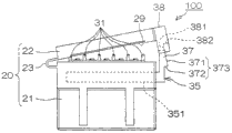
Fig. 2 (a), Fig. 2 (b) and Fig. 2 (c) are the figure of the formation of the expression housing 20 that is used to keep piercing terminal 1.
This housing 20 is made of the one resin forming product of the lid 22 that has the body 21 that is used to keep piercing terminal 1 and can install with respect to this body 21 with opening and closing.Lid 22, the one end is installed in the top of body 21 by 1 pair of linking part 23 of elastically deformable, by being center rotatable cover 22 with linking part 23, but open-close lid 22 when making linking part 23 strains.The vertical view that cover 22 state housing 20 is down opened in Fig. 2 (a) expression, and Fig. 2 (b) represents to open the front view of the housing 20 under 22 the state of covering, and Fig. 2 (c) represents the front view of the housing 20 under the state of closing cap 22.
On the bottom surface of the perforated portion resettlement section 25 of each terminal accommodating recess 24, near the position below perforation projection 2 when the perforated portion 3 with piercing terminal 1 is contained in this perforated portion resettlement section 25 and the kick 9 is formed with slightly OBL towards platform through hole 27.After in each terminal accommodating recess 24, accommodating piercing terminal 1, respectively connect insertion towards platform by following direction towards platform through hole 27 from body 21, make its bearing plane be connected to perforated portion 3 lower board unit 6 below, thereby when pushing the perforation projection 2 of each piercing terminal 1 then from the top, can be by bearing perforated portion 3 from the below towards platform.
According to such formation, by in terminal accommodating recess 24, accommodating after piercing terminal 1 positions, only need towards platform through hole 27 in, connecting on insertion just can make below the lower board unit 6 that is connected to perforated portion 3 towards the bearing plane of platform towards platform, so will be easy with respect to the installation of the perforation connector of flat cable.
In addition, even when a plurality of piercing terminal 1 being installed with respect to flat cable, also can be by accommodating at corresponding terminal accommodating recess 24 after all piercing terminals 1 position, all dash to connect in the platform through hole 27 to insert make towards platform on those bearing plane are connected to below the lower board unit 6 of each piercing terminal 1, and the perforation projection 2 of all piercing terminals 1 once can be bent with drift.Thus, can be on flat cable with a plurality of piercing terminal 1 once mounting, so with piercing terminal 1 is compared with respect to the situation that flat cable is installed one by one, flow chart is few, and is just easier with respect to the installation of the perforation connector of flat cable.
And, owing to be situated between by respectively can whether being housed in each terminal accommodating recess 24 (perforated portion resettlement section 25), from the visual piercing terminal 1 in below (perforated portion 3) so easily towards platform through hole 27.
On the bottom surface of the connecting portion resettlement section 26 of each terminal accommodating recess 24, through hole when the connecting portion 5 with piercing terminal 1 is contained in these connecting portion resettlement sections 26 and connecting portion 5 15 relative to the position on be formed with the slightly terminal through-hole 28 of square shape.Housing 20 (body 21) by making this perforation connector is the housing of chimeric butt joint side-connector from the top, bar-shaped terminal Jie of butt joint side-connector is connected in the through hole 15 of the connecting portion 5 that inserts piercing terminals 1 by terminal through-hole 28, thereby can connect this perforation connector conductively and dock side-connector.
Below lid 22 (state of closing cap 22 under relative with body 21 to face), the front end below this lid 22 is formed with to the rear end and recess 29 with respect to the corresponding shape of section shape that is housed in the flat cable that the interior piercing terminal 1 of this housing 20 will be electrically connected.During closing cap 22, at the recess 29 of this lid 22 and between above the body 21, zoning is formed with the cable through 30 (with reference to Fig. 2 (c)) that is used to make flat cable direction perforation forwards, backwards.Cable through 30, the length of its left and right directions is slightly consistent with the width of flat cable, and the length of its above-below direction (highly) is slightly consistent with the thickness of flat cable.Install at the middle part of flat cable under the state of piercing terminal 1, (do not have basically under the state of kink) simply to connect in cable through 30, can bend flat cable and carry out the daisy chain and connect by making flat cable.
Like this, in this execution mode, perforated portion 3 and connecting portion 5 are situated between by being connected with the linking part 4 of slightly " L " word shape bending, when therefore carrying out the connection of daisy chain with piercing terminal 1, can prevent that flat cable from interfering with connecting portion 5.Thereby the flat cable that can turn back carries out the daisy chain and connects.
Above the body 21, the terminal accommodating recess 24 of the left of the terminal accommodating recess 24 of the leftmost side, the rightmost side right-hand, and adjacent each terminal accommodating recess 24 between, arrange outstanding 2 the perforation walls 31,32 that direction is forwards, backwards extended that are provided with before and after respectively.On the other hand, below lid 22, under the state of closing cap 22 with each connect wall 31,32 relative to the position on be formed with the perforation wall and accommodate recess 33,34, under the state of closing cap 22, each connects wall 31,32 and enters corresponding perforation wall and accommodate in the recess 33,34.Each connects wall the 31, the 32nd, is used to pass locate flat cable in a plurality of through holes on the flat cable that is pre-formed in running through cable through 30.But, be used to locate the perforation projection that runs through the flat cable in the cable through 30, being not limited to is (the connecting wall 31,32) of wall shape, also can be for example bar-shaped.
The top of body 21, from its right flank towards left to being inserted with fixture 35.This fixture 35 is to be used to limit the not parts of displacement upward of the piercing terminal 1 that is contained in each terminal accommodating recess 24 (connecting portion 5), the outside of body 21 is extended the holding section 37 that engages with this lid 22 when being used at closing cap 22 from its right part towards the top.
Fig. 3 is the vertical view that is used to illustrate the situation when perforation connector 100 is installed on flat cable 40.
The flat cable 40 that will be electrically connected with this connector 100 of boring a hole is to have many (for example, 5) conductors 41 and be used for these conductors 41 are spaced from each other certain intervals and the FFC of the maintenance film 42 of parallel maintenance.Each conductor 41 forms thin tabular, by keeping film 42 to sandwich 41 of these conductors, with bonding agent bonding relatively to maintenance film 42 between, thereby form flat cable 40.
On the maintenance film 42 of flat cable 40, between adjacent conductor 41, arrange before and after respectively in advance and be formed with 2 through holes 43,44 that direction is forwards, backwards extended.Each through hole 43,44 is corresponding with perforation wall 31,32 between each terminal accommodating recess 24 that the body 21 of housing 20 is had.It is pointed that the end that the through hole 43,44 of each row is formed on the fore-and-aft direction subtend attenuates gradually.
In addition, keeping the left and right sides edge part of film 42, be formed with 2 otch 45,46 corresponding in advance respectively with 2 right- hand perforation walls 31,32 of the terminal accommodating recess 24 of the left of the terminal accommodating recess 24 of the leftmost side that is located at body 21 respectively and the rightmost side.2 otch 45,46 that are formed in the left side edge portion that keeps film 42 are same shape with the right half part that is formed on 2 through holes in front and back 43,44 between the adjacent conductor 41, and the left-half that is formed on 2 otch 45,46 in the right side edge portion of maintenance film 42 and is formed on 2 through holes in front and back 43,44 between the adjacent conductor 41 is same shape.
When the connector 100 of will boring a hole is installed on the flat cable 40, as shown in Figure 3, in each terminal accommodating recess 24 of body 21, accommodate under the state of piercing terminal 1, flat cable 40 is configured in the top of the body 21 of housing 20 in the mode of direction extension forwards, backwards, by the corresponding perforation wall 31,32 that is formed on the body 21 is connected, thereby flat cable 40 is positioned with respect to perforation connector 100.
Like this, connect, can prevent housing 20 crooking with respect to flat cable 40 by in each through hole 43,44 of flat cable 40 and each otch 45,46, making the corresponding perforation wall 31,32 that is formed on the body 21.Thereby, can suppress piercing terminal 1 in the terminal accommodating recess 24 by being housed in housing 20 with respect to crooking of flat cable 40 and external force is applied to the situation on the joint portion of perforated portion 3 and flat cable 40.But, form 2 formation before and after through hole 43,44 and otch 45,46 are not limited to, also can form more than 3 in front and back.
Fig. 4 A (a), Fig. 4 A (b) and Fig. 4 A (c) and Fig. 4 B (a), Fig. 4 B (b) are the figure that is illustrated in the flow process when perforation connector 100 is installed on the flat cable 40, and the figure of the section of the arrow A-A direction along Fig. 3 is seen in expression from the left side.
When the connector 100 of will boring a hole is installed in flat cable 40, at first, by insertion is connected towards platform 50 from the below respectively towards platform through hole 27, connect in the positioning jack 10 of the perforated portion 3 that inserts each piercing terminal 1 and make from the directing pin 52 of respectively giving prominence to towards the bearing plane 51 of platform 50, thus positional punch portion 3 (reaching (b)) with reference to Fig. 4 A (a).Like this, insert in each positioning jack 10, and can carry out the location of piercing terminal 1 more accurately by making to connect towards the directing pin 52 of platform 50.
By further being moved upward towards platform 50, below the perforated portion 3 of the bearing plane 51 of platform 50 and piercing terminal 1, connect (with reference to Fig. 4 A (c)) from this state.Then, configuration flat cable 40 above the body 21 of housing 20, in each through hole 43,44 of this flat cable 40 and each otch 45,46, connect corresponding connect wall 31,32 after, push flat cable 40 downwards, make perforation projection 2 penetrate into the conductor 41 (with reference to Fig. 4 A (c)) of flat cable 40.
Then, push bending by the projection 2 of will boring a hole from the top with drift 53, perforation projection 2 and kick 9 can connect conductively with respect to the conductor 41 of flat cable 40, and reach the installation (with reference to Fig. 4 B (a)) of piercing terminal 1 with respect to flat cable 40.And, by closing cap 22, each connects wall 31,32 and enters corresponding perforation wall and accommodate in the recess 33,34, becomes flat cable 40 and connects the state of path 30 at fore-and-aft direction, and finish the installation (with reference to Fig. 4 B (b)) of perforation connector 100 with respect to flat cable 40.
In this execution mode, on the following leading section and rearward end of lid 22, be formed with the raised line 54 of direction extension to the left and right respectively, leading section on the body 21 of housing 20 and rearward end are formed with recessed 55 (with reference to Fig. 2 (a) and Fig. 4 B (b)) of direction extension to the left and right respectively.When flat cable 40 back closing caps 22 being installed with respect to piercing terminal 1, by each raised line 54 push downwards fore-and-aft directions extend in cable through 30 flat cable 40 above, thereby the part that is pressed of flat cable 40 is held with the state of bending in recessed 55.
Like this, by near clamping flat cable 40 opening at the two ends (front end and rear end) of cable through 30, can prevent housing 20 crooking or preventing from flat cable 40 with respect to flat cable 40 to piercing terminal 1 transmitting vibrations.Thereby, can suppress on the joint portion of perforated portion 3 that external force is applied to the piercing terminal 1 in the terminal accommodating recess 24 that is contained in housing 20 and flat cable 40.But near the formation of clamping flat cable 40 openings at two ends of cable through 30 is not limited to above-mentioned formation, for example also can be, formation raised line on the body 21 of housing 20, the formation of recessed of formation below lid 22.
On the both ends of flat cable 40, the connector that is connected 300,400 (with reference to Fig. 4 B (b)) of electronic unit that is used for reaching respectively with other is installed.Be installed in the perforation connector 100 on (2 connector 300,400 between) midway of flat cable 40, by for example being installed on the butt joint side-connector 200 that is fixed on the circuit board S, thereby be electrically connected with respect to circuit board S.But butt joint side-connector 200 is not limited to be installed on the circuit board S, for example also can be installed on the other cable.
Butt joint side-connector 200 is the gynetype connectors that have the housing 220 of the chimeric recess 220A that is formed for chimeric perforation connector 100 and give prominence to the bar-shaped terminal 201 in the chimeric recess 220A that is arranged on this housing 220.The chimeric recess 220A of housing 220, has the corresponding shape of shape of bottom with the housing 20 (body 21) of perforation connector 100, the housing 20 of the perforation connector 100 by making male type is entrenched in the chimeric recess 220A of butt joint side-connector 200 from the top, terminal 201 Jie of butt joint side-connector 200 are connected in the through hole 15 of the connecting portion 5 that inserts piercing terminals 1 by terminal through-hole 28, thereby this perforation connector 100 can be connected conductively with butt joint side-connector 200.
Fig. 5 is the vertical view of fixture 35.In addition, Fig. 6 (a) and Fig. 6 (b) are illustrated among the vertical view that inserts the state of fixtures 35 in the body 21 of housing 20, the figure to have omitted lid 22.Fig. 6 (a) expression is inserted into state midway, the state that Fig. 6 (b) expression is inserted into fixture 35 with respect to body 21 leftmost side with respect to body 21 with fixture 35.
Have with reference to Fig. 5 and Fig. 6 (a) and Fig. 6 (b), fixture 35: be used to limit the restrictions 351 of not displacement upward of the piercing terminal 1 that is housed in each terminal accommodating recess 24 (connecting portion 5) and separate certain intervals and flat shape is extended and be used to prevent the linking part 353 of the right part of assisted parts 352 that this fixture 35 comes off from the body 21 of housing 20 and right part that links restrictions 351 and assisted parts 352, slightly be " コ " word shape under the state overlooking with respect to this restrictions 351.The assisted parts 352 of fixture 35, with the pointed formation that its end attenuates gradually, leading section forms the engaging protrusion 352A outstanding towards the rear.
On the back end edge of the restrictions 351 of fixture 35, about arrange be formed be formed on housing 20 on 5 corresponding otch 36 of plan view shape of connecting portion resettlement section 26 of each terminal accommodating recess 24.Promptly, under the state that this fixture 35 is inserted into the position shown in Fig. 6 (a) with respect to the body 21 of housing 20 (linking part 353 is given prominence to the state of some with respect to body 21), each otch 36 is positioned at the top of connecting portion resettlement section 26, and fixture 35 is not positioned at the top of connecting portion resettlement section 26.Under this state, the part between each otch 36 of fixture 35 (middle teat 39) is (front side on the formed below that respectively connects wall 31) between each terminal accommodating recess 24.
In this execution mode, shown in Fig. 6 (a), fixture 35 be not positioned at connecting portion accommodate not 26 above state under (A-stage), piercing terminal 1 is configured in the terminal accommodating recess 24, by this piercing terminal 1 is installed back closing cap 22 with respect to flat cable 40, finish of the installation of perforation connector 100 with respect to flat cable 40.And during closing cap 22, in the process that the holding section 37 of lid 22 outstanding holding section 38 and fixture 35 fastens, fixture 35 is pressed into the leftmost side with respect to body 21 shown in Fig. 6 (b), and the engaging protrusion 352A of assisted parts 352 and body 21 fasten.
Fig. 7 (a), Fig. 7 (b) and Fig. 7 (c) are that 22 the front views of situation of displacement of fixture 35 when closing are covered in expression.
On the right side of holding section 37, be formed with this holding section 37 towards the front end such inclined plane 371 that attenuates gradually, the lower end on this inclined plane 371 is situated between and is connected by the right side of stepped surface 372 with holding section 37.By these inclined plane 371 and stepped surface 372, be formed with the buckle pawl 373 that is used for buckle holding section 37 in the outstanding holding section 38 of lid 22.
The outstanding holding section 38 of lid 22, its inside is hollow form, when closing cap 22, the holding section 37 of fixture 35 enters in the outstanding holding section 38 from front end, the inclined plane 371 of holding section 37 and sliding contact surface 381 sliding contacts (reaching (b) with reference to Fig. 7 (a)) that are formed in the outstanding holding section 38.At this moment, fixture 35 by its inclined plane 371 by on the sliding contact surface 381 that is pressed in outstanding holding section 38 and to the left displacement.
When lid 22 is further closed, when the inclined plane 371 of holding section 37 moves to the top of the sliding contact surface 381 of giving prominence to holding section 38, buckle pawl 373 is crossed the upper end of sliding contact surface 381, thus stepped surface 372 and buckle face 382 butts (with reference to Fig. 7 (c)) that are formed in the outstanding holding section 38.Thus, be indexed at fixture 35 under the state of the leftmost side, the holding section 37 of fixture 35 is with respect to outstanding holding section 38 phase buckles.
Once more, with reference to Fig. 6 (a) and Fig. 6 (b), be pressed under the state of the leftmost side at fixture 35, the fixture 35 under the A-stage between each terminal accommodating recess 24 each in the middle of teat 39 (with reference to Fig. 6 (a)) stretch out to the top of the connecting portion resettlement section 26 of front-left, (with reference to Fig. 6 (b)) stretches out to the top of the connecting portion resettlement section 26 (the connecting portion resettlement section 26 of the rightmost side) of front-left in the right hand edge portion 361 of the otch 36 of the rightmost side of fixture 35 simultaneously.Under this state, be housed in the upper surface of the connecting portion 5 of the piercing terminal 1 (not shown among Fig. 6 (a) and Fig. 6 (b)) in each terminal accommodating recess 24, then with the following butt (with reference to Fig. 4 B (b)) of the middle teat 39 (restrictions) of fixture 35, thereby restriction piercing terminal 1 is not moved upward.Thus, the connecting portion 5 of piercing terminal 1 can be securely fixed in (in the connecting portion resettlement section 26) in the terminal accommodating recess 24, come off from housing 20 so can prevent piercing terminal 1.
In this execution mode, a closing cap 22 just can make fixture 35 to the left displacement, and can fixedly be housed in the piercing terminal 1 in the terminal accommodating recess 24, so can reduce flow chart, can assemble perforation connector 100 easily.
One embodiment of the present invention has been described as mentioned above, but the present invention can implement otherwise also.Housing for example, be not limited to comprise body 21 and cover 22, at these bodies 21 with cover the mode that zoning between 22 forms cable through 30 and constitute, also can be, body and the integrally formed formation of lid, that is, be provided for making flat cable 40 (not having under the state of kink) formation of the cable through of perforation simply in fact outstanding on the housing.
Piercing terminal 1, be not limited at linking part 4 after forwards (with the outstanding direction of perforation projection 2 direction of quadrature slightly) extends from the front end of perforated portion 3, downwards (with the outstanding side of perforation projection 2 in the opposite direction) summary " L " the word shape that extends, (with the outstanding direction rightabout of the perforation projection 2) shape of extending that can be linking part 4 downwards from the position arbitrarily of perforated portion 3, it also can be the shape that linking part 4 extends with respect to the direction inclination predetermined angular opposite with the projection projected direction (for example, less than 90 degree) direction.
Piercing terminal 1 is not limited to accept the formation as the gynetype of the insertion of the terminal 201 of the butt joint side-connector 200 of above-mentioned execution mode, for example also can be, inserts the formation of the male type of piercing terminal with respect to the terminal of butt joint side-connector.In addition, the perforation connector is not limited to be entrenched in the formation as the male type in the chimeric recess 220A of the butt joint side-connector 200 of above-mentioned execution mode, for example also can be, has the formation of the gynetype of the chimeric recess that is used to embed the butt joint side-connector.
In the above-mentioned execution mode, FFC is illustrated as an example of flat cable, but the present invention for example also goes for, FPC (Flexible Printed Circuit) waits other flat cable.
Embodiments of the present invention are had been described in detail, but the concrete example that these only use for technology contents of the present invention is known more, the present invention should not be confined to these concrete examples and make an explanation, and spirit of the present invention and scope limit by technical scheme.
The spy that the application and on October 15th, 2003 propose to Japan Patent office be willing to 2003-355434 number corresponding, all disclosures of the application are quoted it and are obtained.
Claims (8)
1. flat cable terminal is to be used for terminal that the flat cable that flat cable is electrically connected with respect to the terminal of butt joint side-connector is used with electric connector, it is characterized in that, comprising:
Possess the projection on the conductor that will penetrate into flat cable perforated portion and
One end is attached on the above-mentioned perforated portion, to the linking part that extends with the outstanding opposite side of direction of above-mentioned projection and
Be attached on the other end of above-mentioned linking part, be used for the connecting portion that is electrically connected with the terminal that docks side-connector,
Above-mentioned projection by perforation projection (2) with respect to above-mentioned perforation projection (2) via the conductor of flat cable relative to the position on outstanding be provided with and the kick (9) shorter than above-mentioned perforation projection (2) constitutes.
2. flat cable terminal as claimed in claim 1 is characterized in that:
Above-mentioned perforation projection penetrates on the conductor of flat cable, and is fixed on the flat cable by pushing this perforation projected front ends portion of bending,
On above-mentioned perforated portion, be formed for making the directing pin that is located on the platform to connect the positioning jack that inserts, wherein should be used for when pushing above-mentioned projection, bearing above-mentioned perforated portion towards platform.
3. electric connector is to be used for flat cable it is characterized in that with respect to the electric connector that the terminal of butt joint side-connector is electrically connected, and comprises that flat cable is with terminal with keep the housing of this flat cable with terminal;
Above-mentioned terminal, comprise: the perforated portion that possesses the projection on the conductor that will penetrate into flat cable, be attached on the above-mentioned perforated portion with an end and on the linking part that extends with the outstanding opposite side of direction of above-mentioned projection and the other end that is attached at above-mentioned linking part, be used for the connecting portion with the terminal electrical connection of docking side-connector;
Above-mentioned housing, be formed with: be used to accommodate the terminal accommodating portion of above-mentioned flat cable with terminal, with by zoning be contained in above-mentioned terminal accommodating portion in above-mentioned flat cable with the above-mentioned projection of terminal relative to the position on, be used to cable through that flat cable is connected with the state that does not have kink
Above-mentioned housing has near 1 pair of clamping part that the openings at two ends that is formed on above-mentioned cable through is, be used for difference clamping flat cable.
4. electric connector as claimed in claim 3, it is characterized in that: the perforation direction along the flat cable of above-mentioned cable through on above-mentioned housing forms a plurality of perforation projections, and these a plurality of perforation projections penetrate in a plurality of through holes that are formed on this flat cable in that flat cable is run through under the state in the above-mentioned cable through.
5. electric connector as claimed in claim 3 is characterized in that: above-mentioned housing comprises: possess the body of above-mentioned terminal accommodating portion and with respect to the removable lid of this body,
By above-mentioned lid is installed on the above-mentioned body, and zoning forms above-mentioned cable through between above-mentioned lid and above-mentioned body.
6. electric connector as claimed in claim 3, it is characterized in that: the projection of above-mentioned perforated portion, penetrate on the conductor of flat cable, by pushing this projected front ends portion of bending with the state of terminal and be fixed on the flat cable in above-mentioned terminal accommodating portion, to accommodate above-mentioned flat cable;
On above-mentioned housing, be formed be used for by towards platform dash the platform through hole, wherein should when pushing above-mentioned projection, be used to bear above-mentioned perforated portion towards platform.
7. electric connector as claimed in claim 6 is characterized in that: at the above-mentioned flat cable above-mentioned perforated portion with terminal, be formed for connecting the positioning jack that inserts directing pin, wherein this directing pin is located at by in above-mentioned dashing on the platform in the platform through hole.
8. the flat cable of a charged connector is characterized in that:
Comprise: each described electric connector and the flat cable of perforation in above-mentioned cable through in the claim 3~7;
This flat cable by being through with the projection of above-mentioned perforated portion on the middle part of its conductor, and is fixed above-mentioned flat cable terminal by bending this projected front ends portion.
Applications Claiming Priority (3)
| Application Number | Priority Date | Filing Date | Title |
|---|---|---|---|
| JP2003355434A JP2005122988A (en) | 2003-10-15 | 2003-10-15 | Flat cable contact, electric connector, and flat cable with electric connector |
| JP2003355434 | 2003-10-15 | ||
| JP355434/2003 | 2003-10-15 |
Publications (2)
| Publication Number | Publication Date |
|---|---|
| CN1607697A CN1607697A (en) | 2005-04-20 |
| CN100413148C true CN100413148C (en) | 2008-08-20 |
Family
ID=34373575
Family Applications (1)
| Application Number | Title | Priority Date | Filing Date |
|---|---|---|---|
| CNB2004100852934A Expired - Fee Related CN100413148C (en) | 2003-10-15 | 2004-10-15 | Flat cable contact, electrical connector, and flat cable with electrical connector |
Country Status (5)
| Country | Link |
|---|---|
| EP (1) | EP1524726A1 (en) |
| JP (1) | JP2005122988A (en) |
| KR (1) | KR101106066B1 (en) |
| CN (1) | CN100413148C (en) |
| TW (1) | TW200520327A (en) |
Families Citing this family (7)
| Publication number | Priority date | Publication date | Assignee | Title |
|---|---|---|---|---|
| JP2006310007A (en) * | 2005-04-27 | 2006-11-09 | Yazaki Corp | Wire harness assembling method, wire harness, and connector |
| US7922541B2 (en) | 2008-10-17 | 2011-04-12 | Barco Nv | Cable connector |
| JP6002634B2 (en) * | 2013-06-14 | 2016-10-05 | 矢崎総業株式会社 | Flat cable connection structure |
| CN106299772B (en) * | 2016-06-21 | 2019-06-21 | 深圳市敏杰电子科技有限公司 | The method that punching belt is connect with FPC film parallel line |
| WO2020252426A1 (en) | 2019-06-14 | 2020-12-17 | Pica Product Development, Llc | Flat flexible conductive fluid sensor cable and connector |
| US10900859B2 (en) | 2019-06-14 | 2021-01-26 | Pica Product Development, Llc | Conductive fluid sensor cable |
| US11761843B2 (en) | 2019-06-14 | 2023-09-19 | Pica Product Development, Llc | Flat flexible conductive fluid sensor cable and connector |
Citations (7)
| Publication number | Priority date | Publication date | Assignee | Title |
|---|---|---|---|---|
| JPH07220826A (en) * | 1994-01-31 | 1995-08-18 | Yazaki Corp | Connector structure |
| JPH08162228A (en) * | 1994-12-06 | 1996-06-21 | Yazaki Corp | Connector for ffc and its assembly method |
| CN1213870A (en) * | 1997-09-29 | 1999-04-14 | 西门子公司 | Cable plug with earthing joint connection |
| JP2001110247A (en) * | 1999-10-12 | 2001-04-20 | Yazaki Corp | Wire module |
| JP2001210408A (en) * | 2000-01-26 | 2001-08-03 | Yazaki Corp | Terminal retaining structure of flat circuit body |
| CN1407668A (en) * | 2001-08-24 | 2003-04-02 | 日本压着端子制造株式会社 | Electric connector of shielding cable, electric connector body and its manufacture |
| US6616475B2 (en) * | 2000-08-10 | 2003-09-09 | Yazaki Corporation | Electric wire connecting structure of lamp unit |
Family Cites Families (4)
| Publication number | Priority date | Publication date | Assignee | Title |
|---|---|---|---|---|
| DE2738869C2 (en) * | 1977-08-29 | 1985-03-28 | Otto Dunkel GmbH Fabrik für elektrotechnische Geräte, 8260 Mühldorf | Flat cable connection device |
| US4460228A (en) * | 1982-10-12 | 1984-07-17 | Amp Incorporated | Pitch change connector |
| US5122079A (en) * | 1991-04-23 | 1992-06-16 | Amp Incorporated | Multiple conductor cable connector with towers |
| JP4004772B2 (en) * | 2001-11-01 | 2007-11-07 | 日本圧着端子製造株式会社 | Flat flexible cable electric contact, flat flexible cable with electric contact, and method for manufacturing the same |
-
2003
- 2003-10-15 JP JP2003355434A patent/JP2005122988A/en not_active Withdrawn
-
2004
- 2004-10-12 EP EP04256282A patent/EP1524726A1/en not_active Withdrawn
- 2004-10-14 TW TW093131073A patent/TW200520327A/en unknown
- 2004-10-14 KR KR1020040082345A patent/KR101106066B1/en not_active IP Right Cessation
- 2004-10-15 CN CNB2004100852934A patent/CN100413148C/en not_active Expired - Fee Related
Patent Citations (7)
| Publication number | Priority date | Publication date | Assignee | Title |
|---|---|---|---|---|
| JPH07220826A (en) * | 1994-01-31 | 1995-08-18 | Yazaki Corp | Connector structure |
| JPH08162228A (en) * | 1994-12-06 | 1996-06-21 | Yazaki Corp | Connector for ffc and its assembly method |
| CN1213870A (en) * | 1997-09-29 | 1999-04-14 | 西门子公司 | Cable plug with earthing joint connection |
| JP2001110247A (en) * | 1999-10-12 | 2001-04-20 | Yazaki Corp | Wire module |
| JP2001210408A (en) * | 2000-01-26 | 2001-08-03 | Yazaki Corp | Terminal retaining structure of flat circuit body |
| US6616475B2 (en) * | 2000-08-10 | 2003-09-09 | Yazaki Corporation | Electric wire connecting structure of lamp unit |
| CN1407668A (en) * | 2001-08-24 | 2003-04-02 | 日本压着端子制造株式会社 | Electric connector of shielding cable, electric connector body and its manufacture |
Also Published As
| Publication number | Publication date |
|---|---|
| EP1524726A1 (en) | 2005-04-20 |
| KR101106066B1 (en) | 2012-01-25 |
| TW200520327A (en) | 2005-06-16 |
| CN1607697A (en) | 2005-04-20 |
| KR20050036798A (en) | 2005-04-20 |
| JP2005122988A (en) | 2005-05-12 |
Similar Documents
| Publication | Publication Date | Title |
|---|---|---|
| CN100541939C (en) | Socket-type connector and plug-type connector | |
| US7467970B2 (en) | Pair of flat-type flexible cable connectors and harness of flat-type flexible cable | |
| US4687267A (en) | Circuit board edge connector | |
| US6997729B2 (en) | Electrical connector for flat cable | |
| US7575487B2 (en) | Electric connector | |
| US20020094717A1 (en) | Connector assembly for a flat wire member | |
| US5800200A (en) | Smart card connector with IDC | |
| US6514101B1 (en) | Electrical connector for flexible printed board | |
| CN111247701B (en) | Electrical connector | |
| CN102751624A (en) | Electrical connector | |
| JP4563915B2 (en) | Circuit board electrical connector | |
| KR20010098483A (en) | Connector for printed-wiring board | |
| KR101434924B1 (en) | Connector | |
| CN100413148C (en) | Flat cable contact, electrical connector, and flat cable with electrical connector | |
| KR20070032896A (en) | Wire connector | |
| EP1215759B1 (en) | A connector assembly and an electrical connection structure for a flat wire member | |
| US5779498A (en) | Flat cable connector | |
| JP2001052785A (en) | Slider and connector including the same | |
| JP4766421B2 (en) | connector | |
| JP6352676B2 (en) | connector | |
| CN100407509C (en) | Electrical connector and cable with electrical connector | |
| US10559900B2 (en) | Board connector with tool installation space for beding a terminal fitting | |
| JP6002636B2 (en) | Flat cable terminal fitting | |
| US9276341B2 (en) | Connector and connector assembly | |
| CN1614819B (en) | Piercing contact, flat cable and methods of manufacturing the same |
Legal Events
| Date | Code | Title | Description |
|---|---|---|---|
| C06 | Publication | ||
| PB01 | Publication | ||
| C10 | Entry into substantive examination | ||
| SE01 | Entry into force of request for substantive examination | ||
| C14 | Grant of patent or utility model | ||
| GR01 | Patent grant | ||
| CF01 | Termination of patent right due to non-payment of annual fee |
Granted publication date: 20080820 Termination date: 20141015 |
|
| EXPY | Termination of patent right or utility model |