CN100412965C - Disk drive device and spherical aberration correction method - Google Patents
Disk drive device and spherical aberration correction method Download PDFInfo
- Publication number
- CN100412965C CN100412965C CNB2006100740317A CN200610074031A CN100412965C CN 100412965 C CN100412965 C CN 100412965C CN B2006100740317 A CNB2006100740317 A CN B2006100740317A CN 200610074031 A CN200610074031 A CN 200610074031A CN 100412965 C CN100412965 C CN 100412965C
- Authority
- CN
- China
- Prior art keywords
- spherical aberration
- optical disc
- interlayer distance
- aberration correction
- recording layers
- Prior art date
- Legal status (The legal status is an assumption and is not a legal conclusion. Google has not performed a legal analysis and makes no representation as to the accuracy of the status listed.)
- Expired - Fee Related
Links
- 230000004075 alteration Effects 0.000 title claims abstract description 97
- 238000012937 correction Methods 0.000 title claims abstract description 96
- 238000000034 method Methods 0.000 title claims description 24
- 239000010410 layer Substances 0.000 claims abstract description 150
- 230000003287 optical effect Effects 0.000 claims abstract description 133
- 239000011229 interlayer Substances 0.000 claims abstract description 52
- 230000035945 sensitivity Effects 0.000 claims description 12
- 230000008859 change Effects 0.000 claims description 9
- 238000005259 measurement Methods 0.000 claims description 3
- 238000012545 processing Methods 0.000 description 22
- 239000004973 liquid crystal related substance Substances 0.000 description 20
- 238000010586 diagram Methods 0.000 description 6
- 230000005540 biological transmission Effects 0.000 description 5
- 230000004907 flux Effects 0.000 description 4
- 239000000758 substrate Substances 0.000 description 3
- 230000004913 activation Effects 0.000 description 2
- 201000009310 astigmatism Diseases 0.000 description 2
- 238000001514 detection method Methods 0.000 description 2
- 239000002355 dual-layer Substances 0.000 description 2
- 230000000694 effects Effects 0.000 description 2
- 230000001678 irradiating effect Effects 0.000 description 2
- 230000008569 process Effects 0.000 description 2
- 238000002834 transmittance Methods 0.000 description 2
- 238000013461 design Methods 0.000 description 1
- 230000005684 electric field Effects 0.000 description 1
- 230000006870 function Effects 0.000 description 1
- 238000004519 manufacturing process Methods 0.000 description 1
- 230000007246 mechanism Effects 0.000 description 1
- 230000002250 progressing effect Effects 0.000 description 1
- 230000001568 sexual effect Effects 0.000 description 1
- 238000004904 shortening Methods 0.000 description 1
Images


Classifications
-
- G—PHYSICS
- G11—INFORMATION STORAGE
- G11B—INFORMATION STORAGE BASED ON RELATIVE MOVEMENT BETWEEN RECORD CARRIER AND TRANSDUCER
- G11B7/00—Recording or reproducing by optical means, e.g. recording using a thermal beam of optical radiation by modifying optical properties or the physical structure, reproducing using an optical beam at lower power by sensing optical properties; Record carriers therefor
- G11B7/12—Heads, e.g. forming of the optical beam spot or modulation of the optical beam
- G11B7/135—Means for guiding the beam from the source to the record carrier or from the record carrier to the detector
- G11B7/1372—Lenses
- G11B7/1378—Separate aberration correction lenses; Cylindrical lenses to generate astigmatism; Beam expanders
-
- G—PHYSICS
- G11—INFORMATION STORAGE
- G11B—INFORMATION STORAGE BASED ON RELATIVE MOVEMENT BETWEEN RECORD CARRIER AND TRANSDUCER
- G11B7/00—Recording or reproducing by optical means, e.g. recording using a thermal beam of optical radiation by modifying optical properties or the physical structure, reproducing using an optical beam at lower power by sensing optical properties; Record carriers therefor
- G11B7/12—Heads, e.g. forming of the optical beam spot or modulation of the optical beam
- G11B7/135—Means for guiding the beam from the source to the record carrier or from the record carrier to the detector
- G11B7/1392—Means for controlling the beam wavefront, e.g. for correction of aberration
- G11B7/13925—Means for controlling the beam wavefront, e.g. for correction of aberration active, e.g. controlled by electrical or mechanical means
-
- G—PHYSICS
- G11—INFORMATION STORAGE
- G11B—INFORMATION STORAGE BASED ON RELATIVE MOVEMENT BETWEEN RECORD CARRIER AND TRANSDUCER
- G11B7/00—Recording or reproducing by optical means, e.g. recording using a thermal beam of optical radiation by modifying optical properties or the physical structure, reproducing using an optical beam at lower power by sensing optical properties; Record carriers therefor
- G11B7/08—Disposition or mounting of heads or light sources relatively to record carriers
- G11B7/085—Disposition or mounting of heads or light sources relatively to record carriers with provision for moving the light beam into, or out of, its operative position or across tracks, otherwise than during the transducing operation, e.g. for adjustment or preliminary positioning or track change or selection
-
- G—PHYSICS
- G11—INFORMATION STORAGE
- G11B—INFORMATION STORAGE BASED ON RELATIVE MOVEMENT BETWEEN RECORD CARRIER AND TRANSDUCER
- G11B7/00—Recording or reproducing by optical means, e.g. recording using a thermal beam of optical radiation by modifying optical properties or the physical structure, reproducing using an optical beam at lower power by sensing optical properties; Record carriers therefor
- G11B7/08—Disposition or mounting of heads or light sources relatively to record carriers
- G11B7/09—Disposition or mounting of heads or light sources relatively to record carriers with provision for moving the light beam or focus plane for the purpose of maintaining alignment of the light beam relative to the record carrier during transducing operation, e.g. to compensate for surface irregularities of the latter or for track following
- G11B7/0941—Methods and circuits for servo gain or phase compensation during operation
-
- G—PHYSICS
- G11—INFORMATION STORAGE
- G11B—INFORMATION STORAGE BASED ON RELATIVE MOVEMENT BETWEEN RECORD CARRIER AND TRANSDUCER
- G11B7/00—Recording or reproducing by optical means, e.g. recording using a thermal beam of optical radiation by modifying optical properties or the physical structure, reproducing using an optical beam at lower power by sensing optical properties; Record carriers therefor
- G11B2007/0003—Recording, reproducing or erasing systems characterised by the structure or type of the carrier
- G11B2007/0009—Recording, reproducing or erasing systems characterised by the structure or type of the carrier for carriers having data stored in three dimensions, e.g. volume storage
- G11B2007/0013—Recording, reproducing or erasing systems characterised by the structure or type of the carrier for carriers having data stored in three dimensions, e.g. volume storage for carriers having multiple discrete layers
Landscapes
- Physics & Mathematics (AREA)
- Optics & Photonics (AREA)
- Optical Head (AREA)
- Optical Recording Or Reproduction (AREA)
- Moving Of The Head For Recording And Reproducing By Optical Means (AREA)
Abstract
一种盘驱动装置,包括:光拾取器,通过物镜把激光光束照射在具有一或多个记录层的光盘上,并且接收从光盘所反射的激光光束;驱动单元,根据驱动信号,把物镜沿激光光束的光轴方向移动至光盘;层间距离测量单元,测量光盘的多个记录层的层间距离;以及球面像差校正单元,获得球面像差校正值,以校正针对光盘的记录层之一因物镜所导致的球面像差。根据所测量的层间距离以及所获得的针对该一个记录层的球面像差校正值,来获得针对记录层中的另一个记录层的球面像差校正值。
A disc drive device, comprising: an optical pickup, which irradiates a laser beam on an optical disc having one or more recording layers through an objective lens, and receives the reflected laser beam from the optical disc; a drive unit, which drives the objective lens along the The optical axis direction of the laser beam is moved to the optical disc; the interlayer distance measuring unit measures the interlayer distance of a plurality of recording layers of the optical disc; and the spherical aberration correction unit obtains a spherical aberration correction value to correct for A spherical aberration caused by the objective lens. Based on the measured interlayer distance and the obtained spherical aberration correction value for the one recording layer, the spherical aberration correction value for the other one of the recording layers is obtained.
Description
技术领域 technical field
本发明涉及一种适用于具有多个记录层的光盘的盘驱动装置与球面像差校正方法。The invention relates to a disk drive device and spherical aberration correction method suitable for an optical disk with multiple recording layers.
背景技术 Background technique
近些年,作为记录数字数据的记录媒体,总体上使用可记录型光盘。在光盘领域中,具有不同物理特性,同时保持再现兼容性的多种类型的可记录光盘已开发出,并且投入实际的使用。由于这些多种类型的可记录光盘具有等同于只读光盘的记录容量的记录容量,并且具有再现兼容性,所有它们迅速地得以普及。In recent years, recordable optical discs are generally used as recording media for recording digital data. In the field of optical discs, various types of recordable optical discs having different physical characteristics while maintaining reproduction compatibility have been developed and put into practical use. Since these various types of recordable optical discs have a recording capacity equivalent to that of a read-only optical disc and have reproduction compatibility, they are rapidly gaining popularity.
像这样的可记录光盘,CD-R(紧致可记录盘)和CD-RW(紧致可重写盘)作为符合CD(紧致盘)标准的盘,DVD-R(可记录DVD)、DVD+R(DVD+R格式)、DVD-RW(可重写DVD)、DVD+RW(DVD+RW格式)等作为符合DVD(数字多功能盘)标准的盘已为人们所熟悉。由于符合DVD标准的类型的盘的记录容量大到4.7GB(千兆字节)或以上,所以特别显著地普及。Recordable discs like this, CD-R (Compact Disc Recordable) and CD-RW (Compact Disc Rewritable) as discs conforming to the CD (Compact Disc) standard, DVD-R (DVD Recordable), DVD+R (DVD+R format), DVD-RW (DVD Rewritable), DVD+RW (DVD+RW format), etc. are known as discs conforming to the DVD (Digital Versatile Disc) standard. Discs of the type conforming to the DVD standard are particularly remarkably popular because their recording capacities are as large as 4.7 GB (gigabytes) or more.
近几年,随着市场中的进一步提高记录容量的需求,即使针对过去仅用于只读光盘的具有多个记录层的光盘,作为产品的可记录型盘的实现也正在进展。DVD-R双层盘作为具有多个记录层的可记录光盘而为人所知。In recent years, realization of a recordable type disc as a product is progressing even for an optical disc having a plurality of recording layers, which has been used only for a read-only optical disc in the past, in accordance with a demand for a further increase in recording capacity in the market. A DVD-R dual layer disc is known as a recordable optical disc having a plurality of recording layers.
通过把激光光束从光拾取器照射到光盘的记录层上,而执行向光盘的记录和从光盘的再现。即,把激光光束会聚(converge)在记录层上,在记录层上形成光斑。在记录时,通过由激光光束的能量改变记录膜,来形成记录标记。当再现时,通过光电检测器检测来自记录层的激光光束的反射光,并且读取记录标记(槽)。在DVD的情况下,把道(track)间距设置为大约0.74μm,把形成在记录层上的光斑的直径设置为例如大约0.89μm。Recording to and reproduction from an optical disc are performed by irradiating a laser beam from an optical pickup onto a recording layer of the optical disc. That is, the laser beam is converged on the recording layer to form a spot on the recording layer. At the time of recording, recording marks are formed by changing the recording film by the energy of the laser beam. When reproducing, the reflected light of the laser beam from the recording layer is detected by the photodetector, and the recording mark (groove) is read. In the case of DVD, the track pitch is set to about 0.74 μm, and the diameter of the light spot formed on the recording layer is set to, for example, about 0.89 μm.
在光拾取器中,激光光束从激光光束源照射,通过光束分裂器等进入物镜,并且由物镜会聚,从而把光斑形成在光盘的记录层上。因物镜的光学缺陷而导致的球面像差使光斑的图像变形。例如,在执行DVD的记录与再现的情况下,由于必须在记录层上形成具有以上所提到的微直径的光斑,所以希望能够校正球面像差。In an optical pickup, a laser beam is irradiated from a laser beam source, enters an objective lens through a beam splitter, etc., and is converged by the objective lens to form a spot on a recording layer of an optical disc. Spherical aberration caused by optical imperfections of the objective lens distorts the image of the spot. For example, in the case of performing recording and reproduction of DVD, since it is necessary to form a light spot having the above-mentioned micro-diameter on the recording layer, it is desirable to be able to correct spherical aberration.
为了校正球面像差,总体上使用这样一种方法:例如,通过该方法,把已经在其上形成了同心图案的液晶光学器件配置在与盘表面侧相对的物镜的位置上,并且根据预先确定的校正值同心地控制液晶器件的透射率。例如,作为校正值,可以使用通过测量再现抖动所获得的值、再现RF信号的振幅、2-分光电检测器的推挽(push-pull)信号等。在这样的情况下,为了获得校正值,必须分别地执行记录/再现操作。In order to correct spherical aberration, a method is generally used in which, for example, a liquid crystal optical device on which a concentric pattern has been formed is arranged at the position of the objective lens opposite to the disk surface side, and according to a predetermined The correction value of α concentrically controls the transmittance of the liquid crystal device. For example, as the correction value, a value obtained by measuring reproduction jitter, the amplitude of a reproduction RF signal, a push-pull signal of a 2-divided photodetector, or the like can be used. In such a case, in order to obtain correction values, recording/reproducing operations must be performed separately.
由于激光光束进入透射层(基板),沿预先确定的方向折射,并照射至记录层,所以可以根据透射层的厚度来确定球面像差的调整值。JP-A-2003-91851中提出了一种方法,通过该方法,透射层的厚度可通过聚焦搜索来测量,并用于球面像差的校正。Since the laser beam enters the transmission layer (substrate), is refracted in a predetermined direction, and is irradiated to the recording layer, the adjustment value of the spherical aberration can be determined according to the thickness of the transmission layer. JP-A-2003-91851 proposes a method by which the thickness of a transmission layer can be measured by focus search and used for correction of spherical aberration.
发明内容 Contents of the invention
此处,将考虑对具有例如L0层和L1层两个记录层的多个记录层的光盘执行记录和再现的情况。在这样的情况下,由于在L0层的情况下从盘表面到记录层的距离与在L1层的情况下从盘表面到记录层的距离不同,所以即使进行调整以最小化记录层之一中的球面像差,该记录层中的最佳调整值也不同于另一记录层中的最佳调整值。因此,必须针对每一记录层调整球面像差。Here, a case where recording and reproduction are performed on an optical disc having a plurality of recording layers such as two recording layers of an L0 layer and an L1 layer will be considered. In such a case, since the distance from the disk surface to the recording layer in the case of the L0 layer is different from the distance from the disk surface to the recording layer in the case of the L1 layer, even if an adjustment is made to minimize the The spherical aberration of , the optimal adjustment value in this recording layer is also different from the optimal adjustment value in another recording layer. Therefore, spherical aberration must be adjusted for each recording layer.
在具有单一记录层的DVD的情况下,把透射层的厚度设置为600μm±10μm。如果600μm厚度的误差存在于±10μm的范围内,则即使针对600μm的厚度机械地确定调整值,也不存在问题。然而,例如,在DVD的双层盘中,由于把两个记录层之间的间隔设置为大约60μm,在两个记录层中的最佳调整值之间出现很难被忽略的值的差,所以必须针对每一层进行调整。在通过以上所提到的校正值进行调整的过程中,由于每次调整时均需要进行记录与再现以获得校正值,所以在具有多个记录层的盘的情况下,存在着为进行调整花费很长时间的问题。In the case of a DVD having a single recording layer, the thickness of the transmissive layer is set to 600 μm±10 μm. If the error in the thickness of 600 μm exists within the range of ±10 μm, there is no problem even if the adjustment value is mechanically determined for the thickness of 600 μm. However, for example, in the dual-layer disc of DVD, since the interval between the two recording layers is set to about 60 μm, a difference in value that is hardly negligible occurs between the optimum adjustment values in the two recording layers, So it has to be tuned for each layer. In the process of adjusting by the above-mentioned correction value, since it is necessary to perform recording and reproduction to obtain the correction value each time of adjustment, in the case of a disc having a plurality of recording layers, there is a cost for the adjustment. long time question.
例如,当把具有诸如L0层和L1层两个记录层的光盘加载到光盘驱动器中时,首先,光盘驱动器进行聚焦控制,以在L0层上形成光斑。此后,执行记录与再现以获得校正值,并且测量校正值。随后,类似地,光盘驱动器进行聚焦控制,以在L1层上形成光斑。此后,再次执行记录与再现以获得校正值,并且测量校正值。For example, when an optical disc having two recording layers such as an L0 layer and an L1 layer is loaded into an optical disc drive, first, the optical disc drive performs focus control to form a light spot on the L0 layer. Thereafter, recording and reproduction are performed to obtain correction values, and the correction values are measured. Subsequently, similarly, the optical disc drive performs focus control to form a light spot on the L1 layer. Thereafter, recording and reproduction are performed again to obtain correction values, and the correction values are measured.
已经提出了一种方法,通过该方法,形成预先确定的球面像差误差信号,并根据该误差信号动态地校正球面像差。然而,在这样的情况下,存在装置的结构变得复杂以及成本增加的问题。There has been proposed a method by which a predetermined spherical aberration error signal is formed and the spherical aberration is dynamically corrected based on the error signal. However, in such a case, there is a problem that the structure of the device becomes complicated and the cost increases.
因此,希望提供一种盘驱动装置和球面像差校正方法,其中,当使用具有多个记录层的盘时,可以通过简单的结构,在短时间内进行球面像差校正。Therefore, it is desirable to provide a disk drive device and a spherical aberration correction method in which spherical aberration correction can be performed in a short time with a simple structure when a disk having a plurality of recording layers is used.
为了解决上述问题,根据本发明的一个实施例,提供了一种盘驱动装置,包括:光拾取器,通过物镜把激光光束照射在具有一或多个记录层的光盘上,并且接收从光盘所反射的激光光束;驱动单元,根据驱动信号,把物镜沿激光光束的光轴方向移动至光盘;层间距离测量单元,测量光盘的多个记录层的层间距离;以及球面像差校正单元,获得球面像差校正值,以校正针对多个记录层之一而由物镜所导致的球面像差,其中,根据由层间距离测量单元所测量的层间距离、以及由球面像差校正单元所获得的针对该一个记录层的球面像差校正值,而获得针对多个记录层中的另一个记录层的球面像差校正值。In order to solve the above problems, according to one embodiment of the present invention, a disk drive device is provided, including: an optical pickup, which irradiates a laser beam on an optical disk with one or more recording layers through an objective lens, and receives a reflected laser beam; a drive unit for moving the objective lens to the optical disc along the optical axis direction of the laser beam according to the drive signal; an interlayer distance measuring unit for measuring interlayer distances of a plurality of recording layers of the optical disc; and a spherical aberration correction unit, A spherical aberration correction value is obtained to correct spherical aberration caused by the objective lens for one of the plurality of recording layers, wherein, based on the interlayer distance measured by the interlayer distance measuring unit and the spherical aberration correcting unit The obtained spherical aberration correction value for the one recording layer is obtained, and the spherical aberration correction value for the other recording layer of the plurality of recording layers is obtained.
根据本发明的另一个实施例,提供了一种球面像差校正方法,包括:步骤,由光拾取器通过物镜把激光光束照射在具有多个记录层的光盘上,并且接收从光盘所反射的激光光束;层间距离测量步骤,测量光盘的多个记录层的层间距离;以及球面像差校正步骤,获得球面像差校正值,以校正针对多个记录层之一而由物镜所导致的球面像差,其中,根据在层间距离测量步骤中所测量的层间距离、以及在球面像差校正步骤中所获得的针对该一个记录层的球面像差校正值,而获得针对多个记录层中的另一个记录层的球面像差校正值。According to another embodiment of the present invention, a method for correcting spherical aberration is provided, comprising: a step of irradiating a laser beam on an optical disc with multiple recording layers by an optical pickup through an objective lens, and receiving reflected light from the optical disc. a laser beam; an interlayer distance measuring step of measuring an interlayer distance of a plurality of recording layers of the optical disc; and a spherical aberration correcting step of obtaining a spherical aberration correction value to correct for one of the plurality of recording layers caused by the objective lens spherical aberration, wherein the values for the plurality of records are obtained from the interlayer distance measured in the interlayer distance measuring step and the spherical aberration correction value for the one recording layer obtained in the spherical aberration correcting step The spherical aberration correction value of the other recording layer in the layer.
如以上所提到的,根据本发明的实施例,测量具有多个记录层的光盘的多个记录层的层间距离。获得球面像差校正值,以校正针对多个记录层之一而由物镜所导致的球面像差。根据层间距离、以及针对该一个记录层的球面像差校正值,而获得针对多个记录层中的另一个记录层的球面像差校正值。因此,缩短了针对具有多个记录层的光盘的球面像差校正处理的时间。As mentioned above, according to an embodiment of the present invention, the interlayer distance of a plurality of recording layers of an optical disc having a plurality of recording layers is measured. A spherical aberration correction value is obtained to correct spherical aberration caused by the objective lens for one of the plurality of recording layers. The spherical aberration correction value for the other recording layer of the plurality of recording layers is obtained from the interlayer distance, and the spherical aberration correction value for the one recording layer. Therefore, the time for spherical aberration correction processing for an optical disc having a plurality of recording layers is shortened.
根据本发明的实施例,获得具有多个记录层的光盘的多个记录层的层间距离。获得该一个记录层的球面像差校正值。根据层间距离以及针对该一个记录层所获得的球面像差校正值,而获得针对另一个记录层的球面像差校正值。因此,达到可以缩短球面像差校正所需的时间的效果。According to an embodiment of the present invention, interlayer distances of a plurality of recording layers of an optical disc having a plurality of recording layers are obtained. The spherical aberration correction value of the one recording layer is obtained. The spherical aberration correction value for the other recording layer is obtained from the interlayer distance and the spherical aberration correction value obtained for the one recording layer. Therefore, there is an effect that the time required for spherical aberration correction can be shortened.
从而,达到可以缩短光盘驱动装置的激活时间的效果。Therefore, the effect of shortening the activation time of the optical disc drive can be achieved.
通过以下结合附图进行的描述,本发明的其它特性以及优点将会变得十分明显,其中,在本发明的所有图中,以相同的参照标记表示相同或相类似的部分。Other characteristics and advantages of the present invention will become apparent from the following description in conjunction with the accompanying drawings, wherein, in all the drawings of the present invention, the same reference numerals denote the same or similar parts.
附图说明 Description of drawings
图1是方框图,描述了可以施用于本发明的实施例的光盘驱动装置的结构的例子;FIG. 1 is a block diagram illustrating an example of the structure of an optical disc drive apparatus that can be applied to an embodiment of the present invention;
图2是示意图,概念性地描述了光拾取器中的光路径的例子;Fig. 2 is a schematic diagram conceptually describing an example of an optical path in an optical pickup;
图3A~3D为示意图,解释由液晶光学器件进行球面像差的校正调整;3A to 3D are schematic diagrams explaining the correction and adjustment of spherical aberration by liquid crystal optical devices;
图4是示意图,描述了根据柱面透镜的光通量的例子;FIG. 4 is a schematic diagram illustrating an example of light flux according to a cylindrical lens;
图5A~5C为示意图,描述了由光电检测器进行的对激光光束收光的状态;5A-5C are schematic diagrams, which describe the state of receiving light from the laser beam by the photodetector;
图6是示意图,描述了聚焦误差信号的变化的例子;FIG. 6 is a schematic diagram illustrating an example of a change in a focus error signal;
图7示意地描述了具有两个记录层的DVD的层结构;Figure 7 schematically depicts the layer structure of a DVD with two recording layers;
图8A和8B示意地描述了通过使用聚焦误差信号而获得层间距离的方法的例子;以及8A and 8B schematically describe an example of a method of obtaining an interlayer distance by using a focus error signal; and
图9是流程图,描述了根据本发明的实施例的球面像差校正处理的例子。FIG. 9 is a flowchart describing an example of spherical aberration correction processing according to the embodiment of the present invention.
具体实施方式 Detailed ways
以下,将描述本发明的实施例。在本发明中,当把具有多个记录层的光盘加载到驱动器中时,根据通过聚焦搜索所获得的聚焦误差信号,获得多个记录层的层间距离。针对多个记录层之一进行球面像差(SA)校正调整。根据针对一个记录层的球面像差校正调整的结果、和多个记录层的层间距离,来确定另一记录层中的球面像差校正调整值。由于仅针对一个记录层进行球面像差校正调整即可,所以可以缩短球面像差校正调整所需的时间。Hereinafter, embodiments of the present invention will be described. In the present invention, when an optical disc having a plurality of recording layers is loaded into a drive, interlayer distances of the plurality of recording layers are obtained based on a focus error signal obtained through a focus search. Spherical aberration (SA) correction adjustment is performed for one of the plurality of recording layers. The spherical aberration correction adjustment value in another recording layer is determined based on the result of the spherical aberration correction adjustment for one recording layer, and the interlayer distances of the plurality of recording layers. Since it is sufficient to perform spherical aberration correction adjustment for only one recording layer, the time required for spherical aberration correction adjustment can be shortened.
图1描述了可以施用于本发明的实施例的光盘驱动装置1的结构的例子。由微型计算机27控制光盘驱动装置1的整体操作。微型计算机27通过例如微处理器来构造,并且通过使用RAM(未示出)作为工作存储器,根据先前已存储在ROM(只读存储器)(类似地,未示出)中的程序,来控制光盘驱动装置1的操作。优选把其中可重写数据的EEPROM(电可擦除可编程只读存储器)等用作ROM,这是因为可以更新存储在ROM中的程序。因此,使用EEPROM。从例如主机I/F(接口)26提供所更新的程序数据。FIG. 1 depicts an example of the structure of an optical
光盘10通过箝位机制(未示出)安装在主轴马达20的轴21上,并且可以由主轴马达20旋转。The
把光拾取器22安排在面对光盘10的记录表面的位置上。光拾取器22放置在可以由滑板马达23沿光盘10的径向方向将其移动的滑板(sled)24上,并且沿光盘10的径向方向随滑板24一起移动。The
光拾取器22具有激光光束源、光束分裂器、光电检测器、物镜、使物镜可移动的传动器(actuator)等。The
从激光光束源所发射的激光光束通过光束分裂器透射,在微型计算机27的控制下,通过由液晶驱动器51驱动的液晶光学器件50,由物镜会聚,并且照射到光盘10的记录表面上。The laser beam emitted from the laser beam source is transmitted through the beam splitter, passed through the
激光光束由光盘10的记录表面反射,通过物镜进入光束分裂器,由光束分裂器反射,然后到达光电检测器。光电检测器输出相应于入射激光光束的强度的信号。The laser beam is reflected from the recording surface of the
传动器在微型计算机27的控制下由伺服控制单元28驱动,并且沿光轴方向和垂直于光轴的方向(盘径向方向)移动物镜。通过由传动器沿光轴方向移动物镜,进行聚焦控制。通过沿光盘10的径向方向移动物镜,进行跟踪(tracking)控制。The actuator is driven by the
把光拾取器22的输出提供至信号处理单元25。信号处理单元25根据光拾取器22的输出形成聚焦误差信号、跟踪误差信号等,并将其提供至微型计算机27。微型计算机27根据聚焦误差信号和跟踪误差信号把控制信号提供至伺服控制单元28。伺服控制单元28根据所提供的控制信号,提供各种类型的伺服控制,例如主轴伺服、滑板伺服、针对物镜的伺服(聚焦伺服、跟踪伺服)等。The output of the
微型计算机27根据光拾取器22的输出,适当地获得校正值。根据该校正值,微型计算机27校正当把激光光束照射到光盘10的记录层上时所导致的球面像差。由例如一种通过控制液晶驱动器51而驱动液晶光学器件50并且部分地控制激光光束的强度的方法,进行球面像差校正。也可以通过由传动器沿光轴方向移动物镜,进行球面像差校正。另外,也可以通过这两种方法的组合进行球面像差校正。The
已知,球面像差、再现抖动、再现RF信号的振幅、光电检测器的推挽信号等之间存在相关性。因此,可以通过例如一种方法获得校正值,即,使用安排在光盘10的内环侧上的PCA(功率校准区)或导入区中的非记录部分等,来执行试验性写入,并且根据非记录部分的再现信号,测量再现抖动、RF信号、推挽信号等。It is known that there is a correlation among spherical aberration, reproduction jitter, the amplitude of the reproduction RF signal, the push-pull signal of the photodetector, and the like. Therefore, the correction value can be obtained by, for example, a method of performing trial writing using a PCA (Power Calibration Area) arranged on the inner ring side of the
例如,在把再现抖动用作校正值的情况下,对液晶驱动器51进行控制,以沿减小再现抖动的方向驱动液晶光学器件50。在把RF信号或推挽信号的振幅用作校正值的情况下,沿诸如最大化它们的方向控制液晶驱动器51。把用于校正球面像差的控制值(以下,将其称为球面像差校正值)存储在例如在微型计算机27中提供的RAM中。For example, in the case where reproduction jitter is used as the correction value, the
如果加载于光盘驱动装置1中的光盘10为具有两个记录层的双层盘,则可以根据聚焦误差信号和沿光轴方向驱动传动器的驱动信号,获得两个记录层之间的层间距离,以下将对这些细节加以解释。根据如以上所描述的针对两个记录层之一进行球面像差校正所获得的层间距离和球面像差校正值,微型计算机27获得另一记录层中的球面像差校正值。作为获得这样的球面像差校正值的方法,例如,存在一种方法,即,把描述一个记录层中的球面像差校正值和层间距离之间的关系的表预先存储在ROM中,并且参照这样的表获得另一个记录层中的球面像差校正值。也可以通过计算获得这样的值。If the
当记录时,信号处理单元25对通过主机I/F26所提供的记录数据执行误差校正编码处理、记录编码处理等,并且执行预先确定的信号处理,诸如调制处理等,从而形成记录信号。记录信号被提供至光拾取器22,并被调制为激光光束。当再现时,信号处理单元25针对从光拾取器22输出的信号,执行预先确定的处理,诸如RF信号处理、二元化处理、PLL(锁相环路)同步处理、记录代码的解码处理等,并且抽取数字数据。通过主机I/F26,把从信号处理单元25所输出的数字数据传送至外部装置。When recording, the
图2概念性地描述了光拾取器22中光学路径的例子。把从由激光二极管所构造的激光光束源30所发射的激光光束由例如光栅31划分成由第0次(0-th order)光构成的主光束和由第1次光(primary light)构成的两个侧光束,而且,它们通过光束分裂器32进入准直(collimator)透镜33。激光光束由准直透镜33转换成平行光,通过液晶光学器件50进入物镜34,并且由物镜34会聚,然后照射到光盘10的记录表面上。激光光束由光盘10的记录表面反射,并且通过物镜34和准直透镜33进入光束分裂器32。所反射的激光光束由光束分裂器32沿预先确定的方向反射,并且通过柱面透镜35进入光电检测器40。光电检测器40例如为其光敏表面由两条垂直交叉的线划分成4个区域的4-分光电检测器。FIG. 2 conceptually depicts an example of optical paths in the
现在,将参照图3A~3D概要地描述液晶光学器件50对球面像差所进行的校正调整。例如,如图3A中的例子中所示,按这样的方式构造液晶光学器件50,即,安排同心图案52,根据同心图案52,通过施加电场确定液晶的方向,来改变图案52的部分的透射率,并且部分地改变通过液晶光学器件50所透射的激光光束的强度。例如,如果因球面像差而导致存在激光光束的强度变化,如图3B中所示,则由液晶光学器件50部分地控制透射率,从而使激光光束的强度衰减图3C中阴影线区域中示意性描述的量。于是,与图3B中的例子中所示的相比,图3D中示意性示出的激光光束的强度均匀,从而进行了球面像差校正。Now, correction adjustment of the spherical aberration by the liquid crystal
接下来,将参照图4~6示意性地解释通过一种像散(astigmatism)方法进行聚焦误差检测的例子。如图4中示意性描述的,光盘10所反射的激光光束由光束分裂器32反射,并且通过柱面透镜35由光电检测器40接收。Next, an example of focus error detection by an astigmatism method will be schematically explained with reference to FIGS. 4 to 6 . As schematically depicted in FIG. 4 , the laser beam reflected by the
如所熟知的,柱面透镜35仅沿光通量的一个方向(在图4中的例子中为y方向)具有透镜功能。因此,尽管柱面透镜35所转换的聚焦区出现在点B,但该聚焦区不会变成点,而会变成y方向的直线(实际上,为沿y方向延伸的椭圆形状)。当光通过点B时,x方向中的光通量延伸,在点j处与沿y方向的延伸程度一致,从而聚焦区变为圆形。此后,仅y方向的光通量会聚,并且在点A聚焦于沿x方向的直线(实际上,为沿x方向延伸的椭圆形状)。As is well known, the
图5A~5C示意性地描述了以上所提到的激光光束通过柱面透镜35被光电检测器40接收的状态。在图5A~5C中,为了便于解释,把光电检测器40的4个所划分的光敏表面分别标注为A、B、C、D。FIGS. 5A-5C schematically illustrate the state in which the above-mentioned laser beam is received by the
当光盘10和物镜34比焦点位置近时,光电检测器40在图4中的点B处的状态下接收激光光束。如图5A中所示,光电检测器40的光敏表面在沿y方向延伸的椭圆形状中接收激光光束。例如,光盘10和物镜34之间的距离从该状态逐渐增加,光电检测器40在图4中的点j处的状态下,在焦点位置接收激光光束。如图5B中所示,光电检测器40的光敏表面在圆形中接收激光光束。此外,当光盘10和物镜34之间的距离进一步增加时,光电检测器40在图4中点A处的状态下接收激光光束。如图5C中所示,光电检测器40的光敏表面接收激光光束。When the
根据该像散方法,通过使用来自光电检测器40的4个所划分的光敏表面A至D的检测输出,根据对角线方向的光敏表面(A和C)与对角线方向的光敏表面(B和D)之间的差分输出DPP来区分焦点位置,如下列公式(1)中所示:According to this astigmatism method, by using the detection outputs from the four divided photosensitive surfaces A to D of the
DPP=(A+C)-(B+D) ...(1)D PP =(A+C)-(B+D) ...(1)
即,当光斑存在于焦点位置时,由于光电检测器40的光敏表面在圆形中接收激光光束,如图5B中所示,所以差分输出DPP的值等于0。That is, when the spot exists at the focus position, since the photosensitive surface of the
例如,通过在由传动器沿光轴方向适当地移动物镜34的同时,检查差分输出DPP的值的变化,差分输出DPP的值的0交叉点被检测,并且设置成焦点位置。图6描述了当移动物镜34的位置时,差分输出DPP,即聚焦误差信号的变化的例子。如以上所提到的,聚焦误差信号绘出S-特征曲线,在比焦点位置更接近光盘10的位置以及在比焦点位置更远离光盘10的位置,该S-特征曲线具有正和负峰值,而且其在正和负峰值之间相对聚焦误差线性地变化。检测聚焦误差信号中正和负峰值之间的0交叉点。For example, by checking the change in the value of the differential output D PP while appropriately moving the objective lens 34 in the optical axis direction by the actuator, the 0 crossing point of the value of the differential output D PP is detected and set as the focus position. FIG. 6 depicts an example of the variation of the differential output D PP , the focus error signal, when the position of the objective lens 34 is moved. As mentioned above, the focus error signal draws an S-characteristic curve having positive and negative peaks at positions closer to the
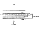
图7示意性地描述了具有两个记录层的DVD的层结构。通过接合具有L0层的基板和具有L1层的基板来形成光盘10,并且把盘表面和中心之间的距离设置为大约600μm。L0层和L1层之间的中间层具有大约60μm(55μm±15μm)的厚度。L0层和L1层每个均具有距盘中心大约30μm的距离。Figure 7 schematically depicts the layer structure of a DVD having two recording layers. The
图8A和8B示意性地描述了一种通过使用聚焦误差信号获得层间距离的方法的例子。在其中检测来自光盘10的反射光,并且根据所检测的反射光通过使用聚焦误差信号来执行聚焦操作的光盘驱动装置1中,在执行聚焦伺服之前,通过聚焦搜索来检测焦点位置,并且预先在某种程度上把物镜34移至靠近焦点位置的位置。通过沿光轴方向移动物镜34并检测以上所提到的聚焦误差信号的S-特征曲线,来执行聚焦搜索。8A and 8B schematically depict an example of a method of obtaining the interlayer distance by using the focus error signal. In the optical
例如,在具有两个记录层的光盘10中,通过在包括L0和L1层的预先确定的范围内移动物镜34,在图8A中的例子中所示的两个位置处检测聚焦误差(FE)信号的S-特征曲线。在通过把物镜34从光盘10的激光光束照射表面移动来执行聚焦搜索的情况下,当排除在光盘10的表面上所检测的S-特征曲线时,首先检测相应于L0层的S-特征曲线SL0,然后检测相应于L1层的S-特征曲线SL1。For example, in an
得到在每一S-特征曲线SL0和SL1的0交叉点处沿光轴方向驱动物镜34的传动器的驱动电压FCS。传动器根据驱动电压FCS移动物镜34,如图8B中的例子中所示。由于根据说明已预先知道传动器的DC灵敏度(即,每单位电压的移动距离),所以可以根据S-特征曲线SL0和SL1的0交叉点处的驱动电压FCS之间的差、和传动器的DC灵敏度,来计算L0和L1层之间的层间距离LD。The driving voltage FCS of the actuator driving the objective lens 34 in the direction of the optical axis at the 0 crossing point of each of the S-characteristic curves S L0 and S L1 is obtained. The actuator moves the objective lens 34 according to the driving voltage FCS, as shown in the example in FIG. 8B. Since the DC sensitivity of the actuator (that is, the moving distance per unit voltage) has been known in advance according to the description, it can be calculated according to the difference between the driving voltage FCS at the 0 crossing point of the S-characteristic curves S L0 and S L1 , and the transmission The DC sensitivity of the detector is used to calculate the interlayer distance L D between the L0 and L1 layers.
当分别假设S-特征曲线SL0和SL1的0交叉点处的驱动电压FCS为FCS_L0和FCS_L1,以及传动器的DC灵敏度为FCS_DC时,可以通过例如以下的公式(2)来计算L0和L1层之间的层间距离LD。When assuming that the driving voltage FCS at the 0 crossing point of the S-characteristic curves S L0 and S L1 is F CS_L0 and F CS_L1 respectively, and the DC sensitivity of the actuator is F CS_DC , it can be calculated by, for example, the following formula (2) Interlayer distance LD between L0 and L1 layers.
LD=FCS_DC×(FCS_L1-FCS_L0) ...(2)L D =F CS_DC ×(F CS_L1 -F CS_L0 ) ...(2)
根据在一个记录层中获得的球面像差校正值,通过使用根据公式(2)所计算的层间距离LD,得到另一个记录层中的球面像差校正值。例如,把一个记录层中所获得的球面像差校正值设置成参照校正值,把根据层间距离LD而预先确定的校正值添加至参照校正值。通过例如这样一种方法获得将被添加的校正值,即,预先形成描述层间距离LD和校正值之间的关系的表,然后根据通过公式(2)所计算的层间距离LD来参照该表。其也可以根据所计算的层间距离LD,通过计算而获得。Based on the spherical aberration correction value obtained in one recording layer, the spherical aberration correction value in the other recording layer is obtained by using the interlayer distance LD calculated according to the formula (2). For example, a spherical aberration correction value obtained in one recording layer is set as a reference correction value, and a correction value predetermined in accordance with the interlayer distance LD is added to the reference correction value. The correction value to be added is obtained by, for example, a method in which a table describing the relationship between the interlayer distance LD and the correction value is formed in advance, and then calculated from the interlayer distance LD calculated by the formula (2). Refer to this table. It can also be obtained by calculation according to the calculated interlayer distance LD .
微型计算机27把按这一方式所获得的L0和L1层中的球面像差校正值适当地设置到液晶光学器件50中,以进行球面像差校正。例如,微型计算机27生成针对液晶驱动器51的命令,以根据与向其执行记录的记录层L0或记录层L1相对应的球面像差校正值,来控制液晶光学器件50。The
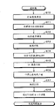
图9是流程图,描述了根据本发明的该实施例的球面像差校正处理的例子。当把光盘10加载于光盘驱动装置1中时,开始聚焦搜索操作(步骤S10)。FIG. 9 is a flowchart describing an example of spherical aberration correction processing according to the embodiment of the present invention. When the
例如,根据来自微型计算机27的命令,伺服控制单元28驱动滑板马达23,并且把光拾取器22移至从光盘10的记录层获得反射光的预先确定的位置。信号处理单元25驱动激光光束源30,以致可把激光光束向光盘10的记录层发射。伺服控制单元28驱动光拾取器22的传动器,以致可以沿光轴把物镜34沿光盘10的方向移动。从光盘10的记录层所反射的激光光束由光拾取器22接收,转换成电信号,然后提供至信号处理单元25。For example, according to a command from the
微型计算机27控制信号处理单元25和伺服控制单元28,根据光拾取器22的输出信号来检测聚焦误差信号的第一S-特征曲线SL0和第二S-特征曲线SL1(参照图8A),分别检测它们的0交叉点,并获得0交叉点处的传动器驱动电压FCS_L0和FCS_L1。把所获得的传动器驱动电压FCS_L0和FCS_L1存储在例如在微型计算机27中提供的RAM中(步骤S11)。The
当聚焦搜索结束时(步骤S12),把光拾取器22的物镜34移至靠近例如L0层的焦点位置的位置。在接下来的步骤S13中,接通聚焦伺服,并且把激光光束聚焦在L0层上。在接下来的步骤S14中,测量传动器的DC灵敏度FCS_DC。When the focus search ends (step S12), the objective lens 34 of the
可以按例如如下方式测量传动器的DC灵敏度FCS_DC。在聚焦伺服为接通的情况下,把预先确定的补偿电压添加至焦点对准(in-focus)状态下的传动器驱动电压FCS,并且检测此时聚焦误差信号的变化。由于预先确定的补偿电压移动了物镜34,所以聚焦状态偏移,从而聚焦误差信号发生变化。把补偿电压设置为例如对于焦点未对准状态S-特征曲线呈线性的范围内的值。The DC sensitivity F CS_DC of the actuator can be measured, for example, as follows. With the focus servo on, a predetermined compensation voltage is added to the actuator drive voltage F CS in the in-focus state, and a change in the focus error signal at this time is detected. As the objective lens 34 is moved by the predetermined compensation voltage, the focus state shifts and the focus error signal changes. The compensation voltage is set to a value within a range where the S-characteristic curve is linear for the out-of-focus state, for example.
针对聚焦误差信号的移位量,光拾取器22具有作为常数的距焦点位置的改变量。在光拾取器22作为产品的情况下,由例如制造公司提供这样的常数。对于传动器的单位驱动电压的传动器的移动距离,即,传动器的DC灵敏度FCS_DC,可以根据添加至传动器驱动电压FCS的补偿电压、聚焦误差信号的改变量、以及距焦点位置的改变量之间的相应关系而获得。The
例如,假设补偿电压设置为ΔFCS,聚焦误差信号的改变量设置为ΔFE,以及光拾取器22的上述常数设置为α,则可以通过以下的公式(3)得到DC灵敏度FCS_DC。For example, assuming that the compensation voltage is set to ΔF CS , the change amount of the focus error signal is set to ΔFE, and the above-mentioned constant of the
FCS_DC=(ΔFE×α)/ΔFCS ...(3)F CS_DC = (ΔFE×α)/ΔF CS ... (3)
可以通过使用如上所述而获得的DC灵敏度FCS_DC、以及在以上所提到的步骤S11中所得到的焦点处的传动器驱动电压FCS_L0和FCS_L1,根据公式(2)来得到L0和L1层之间的层间距离LD。L0 and L1 can be obtained according to formula (2) by using the DC sensitivity F CS_DC obtained as described above, and the actuator driving voltages F CS_L0 and F CS_L1 at the focal point obtained in the above-mentioned step S11 The interlayer distance L D between the layers.
在步骤S15中,通过驱动传动器来移动物镜34,并且执行聚焦伺服,以把激光光束聚焦在L0层上。进行L0层中的球面像差校正调整。作为球面像差校正调整的方法,可以使用已经作为相关技术而描述的使用再现抖动、再现RF信号的振幅、2-分光电检测器的推挽信号等的方法。In step S15, the objective lens 34 is moved by driving an actuator, and focus servo is performed to focus the laser beam on the L0 layer. Perform spherical aberration correction adjustments in the L0 layer. As a method of spherical aberration correction adjustment, a method using reproduction jitter, the amplitude of a reproduction RF signal, a push-pull signal of a 2-divided photodetector, or the like that has been described as the related art can be used.
在接下来的步骤S16中,根据L0层中的球面像差校正值、以及以上所提到的步骤S14中所得到的层间距离LD,来得到L1层中的球面像差校正值。例如,可以参照描述层间距离和添加至L0层中的球面像差校正值的校正值之间的关系、并且已经预先存储在ROM等中的表,而得到L1层中的球面像差校正值。例如,把参照该表根据层间距离LD而获得的校正值添加至L0层中的球面像差校正值,并且把结果值设置为L1层中的球面像差校正值。In the next step S16, the spherical aberration correction value in the L1 layer is obtained according to the spherical aberration correction value in the L0 layer and the interlayer distance LD obtained in the above-mentioned step S14. For example, the spherical aberration correction value in the L1 layer can be obtained with reference to a table describing the relationship between the interlayer distance and the correction value added to the spherical aberration correction value in the L0 layer and which has been stored in ROM or the like in advance . For example, a correction value obtained from the interlayer distance LD with reference to this table is added to the spherical aberration correction value in the L0 layer, and the resultant value is set as the spherical aberration correction value in the L1 layer.
也可以通过计算,而获得添加至L0层中的球面像差校正值的校正值。The correction value added to the spherical aberration correction value in the L0 layer can also be obtained by calculation.
当需要时,通过驱动传动器,把物镜34的焦点位置移至L1层,根据步骤S16中所获得的L1层中的球面像差校正值,来驱动液晶光学器件50,并且进行L1层中的球面像差校正调整(步骤S17)。在接下来的步骤S18中,进行L1层中的其它调整。由于在以上所提到的步骤S15中已得到L1层中的球面像差校正值,所以可以在短时间内执行从L0层到L1层的焦点位置的移动。When needed, the focus position of the objective lens 34 is moved to the L1 layer by driving the actuator, and the liquid crystal
当把光盘10加载到光盘驱动装置1中时,通过执行以上所提到的处理,可以缩短驱动器的激活处理时间。由于能够通过过去所使用的方法来执行获得球面像差校正值的处理,所以不会增加装置的成本,而且还可以容易地进行控制。When the
尽管以上已经参照应用于具有两个记录层的盘的例子而描述了本发明,但本发明并不局限于这样的例子。即,本发明也适用于具有三或三个以上的记录层的盘。另外,盘的种类也不局限于DVD,本发明也适用于其它类型的盘。Although the invention has been described above with reference to an example applied to a disc having two recording layers, the invention is not limited to such an example. That is, the present invention is also applicable to discs having three or more recording layers. In addition, the type of disc is not limited to DVD, and the present invention is also applicable to other types of discs.
本技术领域的技术人员应该意识到,在权利要求和及其等同内容的范围内,可以依据设计要求和其它因素,对本发明进行各种修改、组合、子组合以及替换。Those skilled in the art should realize that within the scope of the claims and their equivalents, the present invention can be variously modified, combined, sub-combined and replaced according to design requirements and other factors.
对相关申请的交叉引用Cross References to Related Applications
本发明包含与2005年4月4日向日本专利局提交的申请号为2005-107176的日本专利申请相关的主题,将其全部内容并入此处作为参考。The present application contains subject matter related to Japanese Patent Application No. 2005-107176 filed in the Japan Patent Office on Apr. 4, 2005, the entire contents of which are hereby incorporated by reference.
Claims (3)
Applications Claiming Priority (2)
| Application Number | Priority Date | Filing Date | Title |
|---|---|---|---|
| JP2005107176A JP2006286132A (en) | 2005-04-04 | 2005-04-04 | Disk drive unit and spherical aberration compensation method |
| JP107176/05 | 2005-04-04 |
Publications (2)
| Publication Number | Publication Date |
|---|---|
| CN1848259A CN1848259A (en) | 2006-10-18 |
| CN100412965C true CN100412965C (en) | 2008-08-20 |
Family
ID=36992566
Family Applications (1)
| Application Number | Title | Priority Date | Filing Date |
|---|---|---|---|
| CNB2006100740317A Expired - Fee Related CN100412965C (en) | 2005-04-04 | 2006-04-04 | Disk drive device and spherical aberration correction method |
Country Status (6)
| Country | Link |
|---|---|
| US (1) | US7551526B2 (en) |
| EP (1) | EP1720162A3 (en) |
| JP (1) | JP2006286132A (en) |
| KR (1) | KR20060106882A (en) |
| CN (1) | CN100412965C (en) |
| TW (1) | TW200703301A (en) |
Families Citing this family (11)
| Publication number | Priority date | Publication date | Assignee | Title |
|---|---|---|---|---|
| US7936646B2 (en) * | 2006-08-15 | 2011-05-03 | Koninklijke Philips Electronics N.V. | Spherical aberration compensation adjustment |
| JP4724624B2 (en) * | 2006-08-29 | 2011-07-13 | パイオニア株式会社 | Optical disk device |
| US7933182B2 (en) * | 2006-12-13 | 2011-04-26 | Canon Kabushiki Kaisha | Optical information recording and reproducing apparatus that sets a movable range of an objective lens based on the type of recording medium |
| JP2008159137A (en) * | 2006-12-22 | 2008-07-10 | Tdk Corp | Optical recording and reproducing method, optical recording and reproducing device, optical recording medium |
| KR100882748B1 (en) | 2007-09-10 | 2009-02-09 | 도시바삼성스토리지테크놀러지코리아 주식회사 | Focus Control Method and Optical Disc Drive Using the Same |
| JP2009158067A (en) * | 2007-12-27 | 2009-07-16 | Toshiba Corp | Spherical aberration correction apparatus and spherical aberration correction method |
| TWI349934B (en) | 2008-01-15 | 2011-10-01 | Mediatek Inc | Method and apparatus for deciding spherical aberration compensation value of optical storage medium |
| JP5463118B2 (en) | 2009-10-23 | 2014-04-09 | 日立コンシューマエレクトロニクス株式会社 | Optical disk device |
| JP2011141915A (en) * | 2010-01-06 | 2011-07-21 | Hitachi Consumer Electronics Co Ltd | Optical disc apparatus |
| JP2011154750A (en) * | 2010-01-27 | 2011-08-11 | Hitachi-Lg Data Storage Inc | Optical disc apparatus, and driving method of optical disc apparatus |
| JP2011248978A (en) * | 2010-05-31 | 2011-12-08 | Hitachi-Lg Data Storage Inc | Optical disk device and optical disk discriminating method |
Citations (5)
| Publication number | Priority date | Publication date | Assignee | Title |
|---|---|---|---|---|
| WO1996028818A1 (en) * | 1995-03-13 | 1996-09-19 | International Business Machines Corporation | Multiple data layer optical disk drive system with fixed aberration correction and optimum interlayer spacing |
| CN1343973A (en) * | 2000-09-06 | 2002-04-10 | 松下电器产业株式会社 | Optical disk device, information recording/reproduction method |
| JP2003091851A (en) * | 2001-09-20 | 2003-03-28 | Tdk Corp | Optical recording and reproducing device |
| CN1503239A (en) * | 2002-11-19 | 2004-06-09 | ������������ʽ���� | Information playback method and information playback device of multi-layer optical disk |
| CN1552065A (en) * | 2002-07-04 | 2004-12-01 | ������������ʽ���� | Optical recording/reproduction device and focal point control method |
Family Cites Families (3)
| Publication number | Priority date | Publication date | Assignee | Title |
|---|---|---|---|---|
| US7286153B1 (en) * | 1991-10-11 | 2007-10-23 | Hitachi, Ltd. | Three-dimensional recording and reproducing apparatus |
| JP3995993B2 (en) * | 2001-06-22 | 2007-10-24 | パイオニア株式会社 | Optical pickup focusing control device and method |
| JP4257049B2 (en) * | 2001-07-06 | 2009-04-22 | パイオニア株式会社 | Multilayer disc recording / reproducing apparatus and focus jump method |
-
2005
- 2005-04-04 JP JP2005107176A patent/JP2006286132A/en active Pending
-
2006
- 2006-03-17 TW TW095109105A patent/TW200703301A/en not_active IP Right Cessation
- 2006-03-22 EP EP06005909A patent/EP1720162A3/en not_active Withdrawn
- 2006-04-03 KR KR1020060029969A patent/KR20060106882A/en not_active Ceased
- 2006-04-04 CN CNB2006100740317A patent/CN100412965C/en not_active Expired - Fee Related
- 2006-04-04 US US11/278,572 patent/US7551526B2/en not_active Expired - Fee Related
Patent Citations (5)
| Publication number | Priority date | Publication date | Assignee | Title |
|---|---|---|---|---|
| WO1996028818A1 (en) * | 1995-03-13 | 1996-09-19 | International Business Machines Corporation | Multiple data layer optical disk drive system with fixed aberration correction and optimum interlayer spacing |
| CN1343973A (en) * | 2000-09-06 | 2002-04-10 | 松下电器产业株式会社 | Optical disk device, information recording/reproduction method |
| JP2003091851A (en) * | 2001-09-20 | 2003-03-28 | Tdk Corp | Optical recording and reproducing device |
| CN1552065A (en) * | 2002-07-04 | 2004-12-01 | ������������ʽ���� | Optical recording/reproduction device and focal point control method |
| CN1503239A (en) * | 2002-11-19 | 2004-06-09 | ������������ʽ���� | Information playback method and information playback device of multi-layer optical disk |
Also Published As
| Publication number | Publication date |
|---|---|
| TWI359419B (en) | 2012-03-01 |
| CN1848259A (en) | 2006-10-18 |
| KR20060106882A (en) | 2006-10-12 |
| US20060221782A1 (en) | 2006-10-05 |
| EP1720162A3 (en) | 2007-08-08 |
| EP1720162A2 (en) | 2006-11-08 |
| US7551526B2 (en) | 2009-06-23 |
| JP2006286132A (en) | 2006-10-19 |
| TW200703301A (en) | 2007-01-16 |
Similar Documents
| Publication | Publication Date | Title |
|---|---|---|
| CN100412965C (en) | Disk drive device and spherical aberration correction method | |
| US20070097809A1 (en) | Method of adjusting spherical aberration and focus offset in optical disk apparatus and optical disk apparatus using the same | |
| KR20040017851A (en) | Focal point adjusting method, and optical pickup device | |
| KR20040018942A (en) | Optical disk apparatus | |
| US20080056077A1 (en) | Method of adjusting spherical aberration and focus offset and information recording/reproduction apparatus using the same | |
| JP4224506B2 (en) | Optical disk device | |
| JP4329364B2 (en) | Optical head, recording and / or reproducing device | |
| US20120163141A1 (en) | Optical disk device, optical pickup, and optical recording medium | |
| JP2009187633A (en) | Optical disk device and optical beam radiation angle adjusting method | |
| US7457221B2 (en) | Optical disc recording/reproduction device | |
| US7602690B2 (en) | Aberration adjustment device, method thereof, optical pickup, and optical information recording apparatus | |
| US7643395B2 (en) | Diffraction element and optical pick-up apparatus having the same | |
| JP2006018974A (en) | Information recorder and information recording medium | |
| JP3692072B2 (en) | Optical disk apparatus adjustment method and optical disk apparatus | |
| CN102693733B (en) | Recording adjusting method and determination method for recommending recording conditions | |
| JP4572824B2 (en) | Focus error signal adjustment method in optical disk apparatus | |
| US20070002704A1 (en) | Optical head and optical disc apparatus | |
| JP2009140573A (en) | Optical disk drive and focus jump method | |
| JP2010044828A (en) | Optical disk device and method for adjusting focus | |
| JP3844296B2 (en) | Inclination amount detection device for optical recording medium and optical pickup device including the same | |
| JP5218414B2 (en) | Optical information reproducing device | |
| JP2005071604A (en) | Adjusting method of optical disk device, and optical disk device | |
| JP2006179037A (en) | Optical disc apparatus and optical disc tilt correction method | |
| JP4699423B2 (en) | Optical disk device | |
| KR20050016276A (en) | Optical recording/reproduction device and focal point control method |
Legal Events
| Date | Code | Title | Description |
|---|---|---|---|
| C06 | Publication | ||
| PB01 | Publication | ||
| C10 | Entry into substantive examination | ||
| SE01 | Entry into force of request for substantive examination | ||
| C14 | Grant of patent or utility model | ||
| GR01 | Patent grant | ||
| C17 | Cessation of patent right | ||
| CF01 | Termination of patent right due to non-payment of annual fee |
Granted publication date: 20080820 Termination date: 20130404 |