CN100409308C - Voice coding method and device and voice decoding method and device - Google Patents
Voice coding method and device and voice decoding method and device Download PDFInfo
- Publication number
- CN100409308C CN100409308C CNB961219424A CN96121942A CN100409308C CN 100409308 C CN100409308 C CN 100409308C CN B961219424 A CNB961219424 A CN B961219424A CN 96121942 A CN96121942 A CN 96121942A CN 100409308 C CN100409308 C CN 100409308C
- Authority
- CN
- China
- Prior art keywords
- coding
- voice signal
- short
- term forecasting
- noise
- Prior art date
- Legal status (The legal status is an assumption and is not a legal conclusion. Google has not performed a legal analysis and makes no representation as to the accuracy of the status listed.)
- Expired - Lifetime
Links
Images


Classifications
-
- G—PHYSICS
- G10—MUSICAL INSTRUMENTS; ACOUSTICS
- G10L—SPEECH ANALYSIS OR SYNTHESIS; SPEECH RECOGNITION; SPEECH OR VOICE PROCESSING; SPEECH OR AUDIO CODING OR DECODING
- G10L19/00—Speech or audio signals analysis-synthesis techniques for redundancy reduction, e.g. in vocoders; Coding or decoding of speech or audio signals, using source filter models or psychoacoustic analysis
- G10L19/02—Speech or audio signals analysis-synthesis techniques for redundancy reduction, e.g. in vocoders; Coding or decoding of speech or audio signals, using source filter models or psychoacoustic analysis using spectral analysis, e.g. transform vocoders or subband vocoders
- G10L19/0212—Speech or audio signals analysis-synthesis techniques for redundancy reduction, e.g. in vocoders; Coding or decoding of speech or audio signals, using source filter models or psychoacoustic analysis using spectral analysis, e.g. transform vocoders or subband vocoders using orthogonal transformation
-
- G—PHYSICS
- G10—MUSICAL INSTRUMENTS; ACOUSTICS
- G10L—SPEECH ANALYSIS OR SYNTHESIS; SPEECH RECOGNITION; SPEECH OR VOICE PROCESSING; SPEECH OR AUDIO CODING OR DECODING
- G10L19/00—Speech or audio signals analysis-synthesis techniques for redundancy reduction, e.g. in vocoders; Coding or decoding of speech or audio signals, using source filter models or psychoacoustic analysis
- G10L19/02—Speech or audio signals analysis-synthesis techniques for redundancy reduction, e.g. in vocoders; Coding or decoding of speech or audio signals, using source filter models or psychoacoustic analysis using spectral analysis, e.g. transform vocoders or subband vocoders
-
- G—PHYSICS
- G10—MUSICAL INSTRUMENTS; ACOUSTICS
- G10L—SPEECH ANALYSIS OR SYNTHESIS; SPEECH RECOGNITION; SPEECH OR VOICE PROCESSING; SPEECH OR AUDIO CODING OR DECODING
- G10L19/00—Speech or audio signals analysis-synthesis techniques for redundancy reduction, e.g. in vocoders; Coding or decoding of speech or audio signals, using source filter models or psychoacoustic analysis
- G10L19/04—Speech or audio signals analysis-synthesis techniques for redundancy reduction, e.g. in vocoders; Coding or decoding of speech or audio signals, using source filter models or psychoacoustic analysis using predictive techniques
- G10L19/06—Determination or coding of the spectral characteristics, e.g. of the short-term prediction coefficients
-
- G—PHYSICS
- G10—MUSICAL INSTRUMENTS; ACOUSTICS
- G10L—SPEECH ANALYSIS OR SYNTHESIS; SPEECH RECOGNITION; SPEECH OR VOICE PROCESSING; SPEECH OR AUDIO CODING OR DECODING
- G10L19/00—Speech or audio signals analysis-synthesis techniques for redundancy reduction, e.g. in vocoders; Coding or decoding of speech or audio signals, using source filter models or psychoacoustic analysis
- G10L19/04—Speech or audio signals analysis-synthesis techniques for redundancy reduction, e.g. in vocoders; Coding or decoding of speech or audio signals, using source filter models or psychoacoustic analysis using predictive techniques
- G10L19/08—Determination or coding of the excitation function; Determination or coding of the long-term prediction parameters
- G10L19/12—Determination or coding of the excitation function; Determination or coding of the long-term prediction parameters the excitation function being a code excitation, e.g. in code excited linear prediction [CELP] vocoders
-
- G—PHYSICS
- G10—MUSICAL INSTRUMENTS; ACOUSTICS
- G10L—SPEECH ANALYSIS OR SYNTHESIS; SPEECH RECOGNITION; SPEECH OR VOICE PROCESSING; SPEECH OR AUDIO CODING OR DECODING
- G10L19/00—Speech or audio signals analysis-synthesis techniques for redundancy reduction, e.g. in vocoders; Coding or decoding of speech or audio signals, using source filter models or psychoacoustic analysis
- G10L19/04—Speech or audio signals analysis-synthesis techniques for redundancy reduction, e.g. in vocoders; Coding or decoding of speech or audio signals, using source filter models or psychoacoustic analysis using predictive techniques
-
- G—PHYSICS
- G10—MUSICAL INSTRUMENTS; ACOUSTICS
- G10L—SPEECH ANALYSIS OR SYNTHESIS; SPEECH RECOGNITION; SPEECH OR VOICE PROCESSING; SPEECH OR AUDIO CODING OR DECODING
- G10L25/00—Speech or voice analysis techniques not restricted to a single one of groups G10L15/00 - G10L21/00
- G10L25/27—Speech or voice analysis techniques not restricted to a single one of groups G10L15/00 - G10L21/00 characterised by the analysis technique
-
- G—PHYSICS
- G10—MUSICAL INSTRUMENTS; ACOUSTICS
- G10L—SPEECH ANALYSIS OR SYNTHESIS; SPEECH RECOGNITION; SPEECH OR VOICE PROCESSING; SPEECH OR AUDIO CODING OR DECODING
- G10L25/00—Speech or voice analysis techniques not restricted to a single one of groups G10L15/00 - G10L21/00
- G10L25/93—Discriminating between voiced and unvoiced parts of speech signals
Abstract
A speech encoding method and apparatus in which an input speech signal is divided in terms of blocks or frames as encoding units and encoded in terms of the encoding units, in which explosive and fricative consonants can be impeccably reproduced, while there is no risk of foreign sound being generated at a transient portion between voiced (V) and unvoiced (UV) portions, so that the speech with high clarity devoid of 'stuffed' feeling may be produced. The encoding apparatus includes a first encoding unit 110 and a second encoding unit 120. The first encoding unit 110 and the second encoding unit 120 are used for encoding a voiced (V) portion and an unvoiced (UV) portion of the input signal, respectively.
Description
The present invention relates to a kind of voice coding method, this method is divided into the voice signal of input as the coding data block of unit or frame and according to the coding unit and decodes, the invention still further relates to a kind of coding/decoding method, encoded signal is decoded, and relate to a kind of voice coding/decoding method.
The existing up to now various coding method that voice signal (comprising voice and acoustic signal) is encoded of being used for according to the psychologic acoustics characteristic of time domain and frequency domain and people's ear, is carried out signal compression by the statistical property of utilizing signal.Coding method can rough segmentation be time domain coding, Frequency Domain Coding and analysis/composite coding.
The example of speech signal coding comprises the sinusoidal analysis coding efficiently, for example harmonic coding or multi-band excitation (MBE) coding, subband coding (SBC), linear predictive coding (LPC), discrete cosine transform (DCT), improved DCT (MDCT) and Fast Fourier Transform (FFT) (FFT).
MBE coding or harmonic coding according to routine utilize noise generation circuit to produce the phonological component of not sending out voiceless consonant.Yet the shortcoming that this method exists is to produce explosion (assisting) sound for example P, K or t realistically, perhaps each friction (assisting) sound.
In addition, for example linear spectral will be right if will have the coding parameter of complete different qualities, in be inserted in sounding (V) part and the transition part office of sounding (UV) between partly not, tend to produce irrelevant external voice.
In addition, utilize conventional sinusoidal composite coding, the voice of low pitch at first are that man's sound can become distortion " blocked " voice.
Therefore, an object of the present invention is to provide a kind of voice coding method and device and tone decoding method and device, therefore can reappear plosive and fricative realistically, not can the sounding language and not the transition part office between the sounding language produce unusual sound, thereby, can reappear the language that has high definition and do not have " obstruction " sense.
According to voice coding method of the present invention, wherein input speech signal is divided into predetermined coding unit and is encoded according to predetermined coding unit sequence ground along time shaft, obtain the surplus portion of short-term forecasting of this input voice signal, utilize encode sinusoidal the decomposition surplus of the short-term forecasting of so obtaining, make input speech signal utilize waveform coding method coding.
Input speech signal is differentiated for confirmation is audible segment or audible segment not.According to the result who differentiates, encode for differentiating, and to be not audible segment utilization analysis and synthetic method handle by the vector quantization along the waveform of time shaft for differentiating for the sounding input speech signal partly utilizes sinusoidal the decomposition.
Encode for sinusoidal analysis, preferably utilize vector or matrix quantization to come the surplus portion of short-term forecasting is quantized by auditory sensation weighting, and, calculate weighting according to the result of the orthogonal transformation of the parameter that derives from by the impulse response of weighting transport function for this vector or the matrix quantization of pressing auditory sensation weighting.
According to the present invention, obtain the surplus portion of the short-term forecasting of input speech signal, the surplus portion of LPC for example, and surplus part utilizing synthetic sine wave to reappear this short-term forecasting, simultaneously, utilize the waveform coding of the transmission of phase of input speech signal that input speech signal is encoded, therefore realize high efficient coding.
In addition, input speech signal is entered discriminating, for confirmation is sounding or audible segment not, according to the result who differentiates, partly utilize sinusoidal analysis to encode to differentiating for the sounding input speech signal, simultaneously partly utilize analysis and synthetic method for differentiating for sounding input speech signal not, search by closed loop best vector, by the vector quantization along the waveform of time shaft is handled, therefore, improved the not ability to express of audible segment, produced the language of reproduction with high definition.Particularly, by promoting speed this effect is strengthened.Can also prevent sounding and not the transition part office between the audible segment produce extra sound, inaccurate synthetic speech has been reduced in the pars stridulans office, thereby produces more natural synthetic video.
Result according to the orthogonal transformation of the parameter that derives from by the impulse response of weighting transport function, by calculating (adding) weight when being transformed to the vector quantization of the weighting of the parameter of the input signal of threshold signal frequently, the quantity of handling can be reduced to an odd value, therefore, simplify the structure or quickened to handle operation.
Fig. 1 is the calcspar of basic structure that expression is used to implement the voice signal encoder (scrambler) of coding method of the present invention.
Fig. 2 is the calcspar of the basic structure of the expression voice signal decoding device (demoder) that is used to implement coding/decoding method of the present invention.
Fig. 3 is the calcspar of the structure more specifically of expression voice coder shown in Figure 1.
Fig. 4 is the calcspar of the more detailed structure of expression voice signal demoder shown in Figure 2.
Fig. 5 is the calcspar of expression LPC quantizer basic structure.
Fig. 6 is the calcspar of the more detailed structure of expression LPC quantizer.
Fig. 7 is the calcspar of the basic structure of expression vector quantizer.
Fig. 8 is the calcspar of the more detailed structure of expression vector quantizer.
Fig. 9 is used to describe the process flow diagram of a particular instance that compute vectors quantizes the sequence of operation of used weighting weight.
Figure 10 is the square circuit diagram of concrete structure of the CELP coded portion (second coded portion) of expression voice coder of the present invention.
Figure 11 is a process flow diagram of describing the treatment scheme in the device shown in Figure 10.
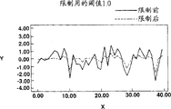
Figure 12 represents the state of Gaussian noise and noise after different threshold values place limit.
Figure 13 is the process flow diagram of the treatment scheme when being illustrated in by study generation waveform (shope) code book.
Figure 14 description is right by the 10 rank linear spectral that 10 rank lpc analysis obtain the alpha parameter derivation.
Figure 15 describes the change in gain mode from the UV frame to the V frame.
Figure 16 describes the mode and the synthetic frame by frame waveform of the interpolation of frequency spectrum.
Figure 17 be described in sounding (V) part and not the joint portion between sounding (UV) part locate overlapping mode.
The noise that Figure 18 is described in when synthesizing the sound (part) of sending out voiced sound adds operation.
Figure 19 is described in the example of the amplitude calculating of the noise that adds when synthesizing the sound (part) of sending out voiced sound.
Figure 20 describes the example that a postfilter constitutes.
Figure 21 describes the filter coefficient refresh cycle of gain refresh cycle and postfilter.
Figure 22 is described in the processing procedure of joint portion of the frame boundaries of the gain of postfilter and filter coefficient.
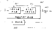
Figure 23 is the calcspar of the transmitter side structure of the expression portable terminal that adopts voice coder of the present invention.
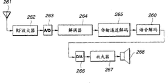
Figure 24 is the calcspar of the receiver side structure of the expression portable terminal that adopts voice signal demoder of the present invention.
Below, will explain each preferred embodiment of the present invention in detail with reference to accompanying drawing.
Fig. 1 represents to be used to implement the basic structure of the code device (scrambler) of voice coding method of the present invention.
The key concept that constitutes voice coder shown in Figure 1 is, this scrambler has first coding unit 110 and second coding unit 120, first coding unit 110 is used to obtain the surplus portion of the short-term forecasting of input speech signal, the surplus portion of for example linear predictive coding (LPC), so that carry out sinusoidal analysis, second coding unit 120 is used to utilize the waveform coding with phase reconstruction ability that input speech signal is encoded; Be that also first coding unit 110 and second coding unit 120 are respectively applied for that sounding (V) voice to input signal are encoded and encode for not sounding (UV) part of input signal.
First coding unit 110 adopts the sinusoidal analysis coding, for example harmonic coding or multi-band excitation (MBE) the coding structure of for example the surplus portion of LPC being encoded.Search and also for example utilize the synthetic method analysis by closed loop by carrying out for second coding unit 120, searches best vector by closed loop and utilize vector quantization, adopts the structure of the linear prediction (CELP) of implementing code exciting.
In the embodiment shown in fig. 1, the voice signal that is sent to input end 101 is sent to the quantifying unit 113 of LPC inverse transformation wave filter 111 and the lpc analysis and first coding unit 110.The inverse transformation wave filter 111 that utilizes LPC coefficient that lpc analysis quantifying unit 113 obtains or so-called alpha parameter to deliver to first coding unit 110.Obtain surplus (the surplus portion of LPC) of line prediction of input speech signal from LPC inverse transformation wave filter 111.Obtain the right quantification output (LSPs) of each linear spectral and be sent to output terminal 102 (hereinafter will explain) by lpc analysis quantifying unit 113.Surplus portion from the LPC of LPC inverse transformation wave filter 111 is sent to sinusoidal analysis coding unit 114.Sinusoidal analysis coding unit 114 carries out pitch detection and calculates the amplitude of spectral enveloping line, and utilizes V/UV discriminating unit 115 to carry out V/UV and differentiate.Data from the spectral enveloping line amplitude of sinusoidal analysis coding unit 114 are delivered to vector quantization unit 116.Code book index from vector quantization unit 116 is delivered to output terminal 103 as the output of the vector quantization of spectral enveloping line through switch 117, and the output of sinusoidal analysis coding unit 114 is delivered to output terminal 104 through switch 118.The V/UV of V/UV discriminating unit 115 differentiates to export and delivers to output terminal 115, and delivers to switch 117,118 as a control signal.If input speech signal is sounding (V) part, then select this index and tone and taking-up at output terminal 103,104 respectively.
In the present embodiment, second coding unit 120 shown in Figure 1 has a kind of linear predictive coding (CELP coding) structure of code exciting, and adopt synthetic method analysis and utilization closed loop to search time domain waveform is carried out vector quantization, according to synthetic method, utilize the output of the composite filter composite noise code book 121 of weighting, subtracter 123 delivered in the voice of formed weighted, through the voice of weighted and be provided between the voice signal on the input end 101 and therefore through taking out an error by auditory sensation weighting wave filter 125, therefore the error of obtaining is delivered to distance calculation circuit 124, so that effectively calculate and utilize noise code this 121 searches a vector that makes the error minimum.Such CELP coding is used for voiced speech is not partly encoded, as explained earlier.The code book index is as taking out at output terminal 107 through switch 127 from these UV data of 121 of noise code, and this switch 127 is connected during for sounding (UV) part not as the result of V/UV discriminating.
Fig. 2 is that expression is used to implement tone decoding method of the present invention, as the calcspar of the basic structure of the voice signal demoder of the corresponding intrument of voice coder shown in Figure 1.
With reference to Fig. 2, the code book index is delivered to input end 202 as the linear spectral from output terminal shown in Figure 1 102 to the quantification output of (LPSs).The output of the output terminal 103,104,105 among Fig. 1 is that tone, V/UV differentiate output and index data, quantizes output data as envelope and is provided to input end 203 to 205 respectively.Being used as not, the index data of sounding data is provided to input end 207 by the output terminal among Fig. 1 107.
The index that quantizes output as the envelope of input end 203 is delivered to one and is used for the anti-vector quantization unit 212 of anti-vector quantization, so that obtain the spectral enveloping line of the surplus portion of LPC, this envelope is delivered to sounding (part) voice operation demonstrator 211 again.The voice operation demonstrator 211 of audible segment is utilized the sinusoidal surplus portion that synthesizes to synthesize voiced speech linear predictive coding (LPC) partly.Compositor 211 also is provided to differentiate output from the tone of input end 204,205 and V/UV.Surplus portion from the LPC of the voice of the audible segment of the voice operation demonstrator of audible segment delivers to LPC composite filter 204.Index data from the UV data of input end 207 is delivered to the not sound synthesis unit 220 of sounding (part), in this unit in order to take out the not surplus portion of the LPC of audible segment, must with reference to noise code this.In LPC composite filter 214, utilize the condition of the synthetic LPC to audible segment of LPC and not the surplus portion of LPC of sounding handle.In addition, can utilize surplus of the synthetic LPC to audible segment of LPC and not surplus the sum of the LPC of audible segment handle.Deliver to LPC parameter reproducing unit 213 from the LSP index data of input end 202, take out the alpha parameter of LPC therein and deliver to LPC composite filter 214.Take out the voice signal that synthesizes by LPC composite filter 214 at output terminal 201.
With reference to Fig. 3, the more detailed structure of the voice coder shown in explained later Fig. 1.In Fig. 3, the numeric character identical with the similar use of the element shown in Fig. 1 marks.
In voice coder shown in Figure 3, the voice signal that is provided on the input end 101 utilizes Hi-pass filter HPF109 to carry out filtering, so that remove signal that does not need scope and lpc analysis circuit 132 and the inverse transformation LPC wave filter 111 that is provided to lpc analysis/quantifying unit 113 from this wave filter.
The lpc analysis circuit 132 of lpc analysis/quantifying unit 113 provides a Hamming window, and the length of waveform input signal of 256 samplings of order is as a data block, and utilizes correlation method to obtain linear predictor coefficient, promptly so-called side reaction coefficient.Interval as the frame of a data output unit is set near 160 sampled points.If sample frequency fs for example is 8 kilo hertzs, a frame period then is 20 milliseconds or 160 sampled points.
Deliver to α-LSP translation circuit 133 from the alpha parameter of lpc analysis circuit 132, so that be transformed into linear spectral to (LSP) parameter.When utilizing direct mode filter coefficient to obtain, this alpha parameter for example is transformed to 10 5 pairs of LSP parameters.This conversion for example utilizes Newton-Raphson's method to realize.The reason that alpha parameter is transformed into the LSP parameter is the interpolation characteristic according to alpha parameter, and this LSP parameter is more excellent.
LSP parameter from α-LSP translation circuit 133 is carried out matrix or vector quantization by LSP quantizer 134.Can before carrying out vector quantization, get frame by frame poor, perhaps compile a plurality of frames, so that carry out matrix quantization.According to this example, per 20 millisecond meters are calculated the LSP parameter, and each two frame of long 20 milliseconds utilizes matrix quantization and the vector quantization to handle together.
In the quantification output that link 102 takes out quantizer 134, i.e. the index data of LSP quantification is delivered to LSP interpolating circuit 136 with the LSP vector that quantizes simultaneously.
The LSP vector of 136 pairs of per 20 milliseconds or 40 milliseconds quantifications of LSP interpolating circuit carries out interpolation, so that 8 tuple speed are provided.Be per 2.5 milliseconds and refresh the LSP vector.Reason is, if utilize harmonic coding/coding/decoding method by analyzing/the synthetic waveform of handling this surplus portion, the envelope of synthetic waveform is rendered as very level and smooth waveform, like this, if the LPC coefficient changes for per 20 milliseconds sharp, produce outside noise probably.If promptly the LPC coefficient little by little changes for per 2.5 milliseconds, can prevent the generation of this external noise.
Because utilize the LSP vector of the interpolation of per 2.5 milliseconds of generations that the language of input is carried out inverse transformation filtering, the LSP parameter utilizes one to be transformed to alpha parameter by LSP to α translation circuit 137, they are for example to be the filter coefficient of 10 rank direct-type wave filters.Deliver to LPC inverse transformation filter circuit 111 by LSP to the output of α translation circuit 137, this circuit utilizes per 2.5 milliseconds of alpha parameters that refresh to carry out inverse transformation filtering then, so that produce level and smooth output.The orthogonal intersection inverter (for example DCT circuit) of sinusoidal analysis coding unit 114 (for example harmonic coding circuit) is delivered in the output of anti-LPC wave filter 111.
Alpha parameter from the lpc analysis circuit 132 of lpc analysis/quantifying unit 113 is delivered to a filtering counting circuit 139 by auditory sensation weighting, obtains the coefficient that is used for by auditory sensation weighting therein.The data of these weightings are delivered to by the wave filter of pressing auditory sensation weighting 125 in vector quantizer 116, the second coding units 120 of auditory sensation weighting and are pressed the composite filter 122 of auditory sensation weighting.
The sinusoidal analysis coding circuit 114 of harmonic coding circuit utilizes the harmonic coding method to analyze the output of inverse transformation LDC wave filter 111.Promptly carry out the calculating of amplitude Am of pitch detection, each harmonic wave and the discriminating of audible segment (V)/not audible segment (UV), and utilize the conversion of dimension to make digital constant with the amplitude Am of tonal variations or envelope of each harmonic wave.
In the illustrative example of sinusoidal analysis coding unit 114 shown in Figure 3, use p.m.entry formula harmonic coding.Particularly, when modelling, suppose according to multi-band excitation (MBE) coding, point (identical data block or frame) at one time, audible segment and not audible segment appear in each frequency domain or the frequency band.According to another kind of harmonic coding technology, differentiate voice in a data block or frame singlely and be audible segment or audible segment not.In the introduction below, if all frequency bands all are UV, then the differentiation of the frame of an appointment is UV, is such with regard to the MBE coding.Can be to find in the Japanese patent application of 4-91442 in sequence number for the particular instance of the technology of the analysis synthetic method of MBE as mentioned above with the application's assignee's name application.
To search unit 141 and zero crossing counter 142 from the input speech signal of input end 101 with from the open loop tone that the signal of Hi-pass filter (HPF) 109 is provided to the sinusoidal analysis coding unit 114 shown in Fig. 3 respectively.Be provided to the orthogonal intersection inverter 145 of sinusoidal analysis coding unit 114 from the surplus portion of surplus of the LPC of inverse transformation LPC wave filter 111 or linear prediction.The open loop tone is searched the surplus portion that unit 141 takes out the LPC in the input signals, carries out rough relatively tone and searches so that search by open loop.The rough tone data that utilizes closed loop to search to be extracted is delivered to trickle tone and is searched unit 146, will make an explanation below.By the open loop tone search that unit 141 takes out that the autocorrelative maximal value normalization of the surplus portion by making LPC obtains through the maximal value of normalized autocorrelation value rp together with this rough tone data, so that deliver to V/UV discriminating unit 115.
Searching unit 146 to trickle tone provides by the open loop tone and searches rough relatively tone data that unit 141 extracts and the frequency domain data that is obtained by orthogonal transform unit 145.Trickle tone is searched unit 146 and is made this tone data swing with 0.2 to 0.5 speed by ± these rough pitch value data that several samplings center on as the center tone data, so that unlimited near best decimal system point (floating-point) is arranged.With the analysis that utilizes synthetic method to carry out as selecting the trickle technology of searching of a tone, so that make the power spectrum can be near the power spectrum of original sound.Search the tone data of unit 146 from the trickle tone of closed loop and deliver to output terminal 104 through switch 118.
In frequency spectrum calculation element 148, the amplitude of each harmonic wave and calculate according to spectral magnitude with as the tone of the orthogonal transformation output of the surplus portion of LPC as the spectral enveloping line of each harmonic wave sum, and deliver to that trickle tone is searched unit 146, V/UV discriminating unit 115 and by the vector quantization unit 116 of auditory sensation weighting.
V/UV discriminating unit 115 according to the output of orthogonal intersection inverter 145, from trickle tone search the best tone of unit 146, from the spectral magnitude data of frequency spectrum computing unit 148, search the normalized autocorrelation value r (P) of unit 141 and the V/UV that differentiates a frame from the over-zero counting value of zero passage register 142 from the open loop tone.In addition, the boundary position of differentiating for the V/UV baseband of MBE can also be as the discrimination condition of V/UV base band.Take out the discriminating output of V/UV discriminating unit 115 at output terminal 105.
The input block of the output unit of frequency spectrum computing unit 148 or vector quantization unit 116 is provided with some data conversion unit (a kind of unit that carries out sample-rate-conversion), consider along the number of the number of the frequency band division of frequency axis and data differently with tone, the number of data conversion unit is used for the amplitude data 1Am1 of envelope is set at a constant numerical value.If promptly effectively frequency band is up to 3400 kilo hertzs, then this effective frequency band can be divided into 8 to 63 frequency bands according to tone.The number of the mMx+1 of the amplitude data 1Am1 that is obtained by frequency band one by one changes in from 8 to 63 scope.Therefore, data number converter unit is the data of preset number with the amplitude data conversion of variable number mMX+1, for example 44 data.
From data number converter unit, at the output unit place of frequency spectrum computing unit 148 or the preset number M that provides at the input block place of vector quantization unit 116 for example 44 amplitude data or envelop data, data according to preset number, for example 44 data are as a unit, utilize vector quantization unit 116 to handle together by the quantification of the vector that is weighted.Provide this weighting weight by output by the wave filter counting circuit 139 of auditory sensation weighting.Take out the index of envelope by vector quantizer 116 at output terminal 103 through switch 117.Before the vector quantization of weighting, can utilize " leakage " coefficient that is suitable for for a vector that constitutes by the present count destination data to draw the interior difference of frame.
Explained later second coding unit 120.Second coding unit 120 has a so-called CELP coding structure, and is specifically designed to the not audible segment of voice signal of input is encoded.LELP coding structure at the not audible segment that is used for input speech signal, as noise code this or so-called at random the representational output valve of code book 121, deliver to composite filter 122 by auditory sensation weighting through gain control circuit 126 with surplus the corresponding noise output of the LPC of voiced speech part not.The composite filter 122LPC of this weighting utilizes the LPC synthetic method synthetic and the signal of the not sounding (part) of the weighting that produced delivered to subtracter 123 to the noise of input.To subtracter 123 by input end 101 through Hi-pass filter (HPF) 109 that provide and by by the wave filter 125 of auditory sensation weighting through signal by auditory sensation weighting.Subtracter is obtained this signal and from difference between the signal of composite filter 122 or error.Simultaneously, by the zero input sensitivity that deducts in advance in the output by the filter output 125 of auditory sensation weighting by the composite filter of auditory sensation weighting.This error is delivered to a distance calculation circuit 124, so that computed range.Finding in noise code basis 121 makes this error become a minimum representational vector value.Above-mentioned is by utilizing the synthetic method analysis to adopt the summary of the vector quantization of the time domain waveform that closed loop searches.
As not sounding (UV) partial data, by the waveform index of this 121 taking-up code book of noise code and the gain gain of taking out code books by gain circuitry 126 from second scrambler 120 that adopts the CELP coding structure.As waveform index, deliver to output terminal 107S through switch 127S, and deliver to output terminal 107g through switch 127g as the gain index of the UV data of gain circuitry 126 from these UV data of 121 of noise code.
These switches 127S, 127g and switch 117,118 depend on that the V/UV identification result from V/UV discriminating unit 115 switches on and off.Specifically, if the V/UV identification result of the voice signal of the frame of current transmission is indicated as audible segment (V), switch 117 and 118 is connected, and if the voice signal of the frame of current transmission is audible segment (UV) not, then switch 127S, 127g connection.
The more detailed structure of the voice signal demoder shown in Fig. 4 presentation graphs 2.In Figure 14, use identical number mark and corresponding part shown in Fig. 2.
In Fig. 4, be that the code book index is provided to input end 202 corresponding to the vector quantization output of the LSP of the output terminal of Fig. 1 and 3.
The anti-vector quantizer 231 of the LSP that is used for LPC parameter reproducing unit 213 delivered in the LSP index, so that linear spectral is carried out anti-vector quantization to (LSP) data, and then is provided to the LSP interpolating circuit 232,233 that is used for interpolation.Formed interpolative data utilization is transformed to alpha parameter from LSP to α translation circuit 234,235, delivers to LPC composite filter 214 again.LSP interpolating circuit 232 and be sounding (V) voice (part) design to α translation circuit 234, and LSP interpolating circuit 233 and be sounding (UV) phonological component design to α translation circuit 235 from LSP from LSP.LPC composite filter 214 is made of the LPC composite filter 236 of voiced speech part and the LPC composite filter 237 of not sending out the phonological component of voiceless consonant.Promptly, for voiced speech part and not the voiced speech part carry out LPC coefficient interpolation independently, in order to suppressing injurious effects, otherwise from the voiced speech part to voiced speech part not or the opposite transformation transition portion since interpolation have complete LSP of different nature and produce this influence probably.
Provide and code index data to input end shown in Figure 4 203 corresponding to the spectral enveloping line Am of the vector quantization of the corresponding weighting of the output of the link 103 of the scrambler in Fig. 1 and 3, provide tone data to input end 204, and provide V/UV authentication data from the link among Fig. 1 and Fig. 3 105 to input end 205 from the link among Fig. 1 and Fig. 3 104.
Vector quantization index data from the spectral enveloping line Am of input end 203 is delivered to the anti-vector quantizer 212 that is used to carry out anti-vector quantization, carries out therein and the opposite conversion of data number conversion.Formed spectral enveloping line data are delivered to a sinusoidal combiner circuit 215.
If in cataloged procedure, before frequency spectrum is carried out vector quantization, obtain the difference in the frame, then after anti-vector quantization, the difference in the frame is decoded, so that produce the envelop data of frequency spectrum.
Provide from the tone of input end 204 with from the V/UV authentication data of input end 205 to sinusoidal combiner circuit 215.By surplus the data of the corresponding LPC of output of the LPC inverse transformation wave filter 111 shown in sinusoidal combiner circuit 215 taking-ups and Fig. 1 and 3 and deliver to totalizer 218.It is in the Japanese patent application of 4-91442 and 6-198451 that sinusoidal synthetic concrete technology is disclosed in the sequence number that is for example proposed by this assignee.
The envelop data of anti-vector quantizer 212 and deliver to the noise combiner circuit 216 that is used for audible segment (V) is added noise from the tone of input end 204,205 and V/UV authentication data.The output of noise combiner circuit 216 is delivered to totalizer 218 through weighted stacking with interpolation circuit 217.Specifically, consider if by the sinusoidal wave synthetic incentive action that produces conduct to the input of the LPC composite filter of voiced speech part, this noise is joined the audible segment of surplus signal of LPC, then can produce the sensation of the sound that is in low pitch, man's voice for example, and in voiced speech part with do not change suddenly between the voiced speech part, produce the factitious sense of hearing.This noise is considered the parameter relevant with the speech coding data, the level of the signal of the amplitude of tone, spectral enveloping line, the maximum amplitude in a frame or surplus portion for example, with the LPC composite filter input associated of voiced speech part, promptly with the incentive action associated.
The addition result of totalizer 218 is delivered to the composite filter 236 of the voiced speech part that is used for LPC composite filter 214, it is synthetic to carry out LPC therein, produce Wave data in time, utilize a postfilter 238V who is used for the voiced speech part to carry out filtering then, deliver to totalizer 239 again.
Input end 207S in Fig. 4 and 207g provide waveform index and the gain index of conduct from the UV data of output terminal 107S among Fig. 3 and 107g respectively, are provided to the not synthesis unit 220 of voiced speech part from this input end.Deliver to the not noise code basis 221 of the synthesis unit 220 of voiced speech part from the waveform index of link 207s, and deliver to gain circuitry 222 from the gain index of link 207g.By this 221 representational numerical value output of reading of noise code be and surplus the corresponding noise signal component of the LPC of voiced speech part not.It becomes the gain amplitude that presets and delivers to window circuit 223 increasing to cover in circuit 222, so that be formed for smoothing to the window of the joint portion of voiced speech part.
The composite filter 237 of not sounding (UV) phonological component that is used for LPC composite filter 214 is delivered in the output of window circuit 223.The data of delivering to composite filter 237 utilize that LPC is synthetic to be handled, and become to be used for the not Wave data in time of audible segment.Before delivering to totalizer 239, utilize a postfilter that is used for audible segment 238u not that the Wave data in time of audible segment is not carried out filtering.
In totalizer 239, will from the waveform signal in time of the postfilter 238V that is used for voiced speech part and from the postfilter 238u that is used for voiced speech part not for the not addition each other of waveform signal in time of voiced speech part, take out formed summed data at output terminal 201.
Above-mentioned voice coder can have the data of different bit rates according to desired sound quality output.That is, can utilize variable bit rate to export this output data.For example, if low bit rate is 2 kilobits/second, high bit rate is 6 kilobits/second, and then Shu Chu data are the data that have as in the following bit rate as shown in the table 1.
Table 1

From the tone data of output terminal 104 for the voiced speech part all the time according to the bit rate output of 8 bits/20 millisecond, and differentiate that from the V/UV of output terminal 105 output is always 1 bit/20 millisecond.What be used for that LSP quantizes is changed between 32 bits/40 millisecond and 48 bits/40 millisecond by the index of output terminal 102 outputs.On the other hand, changing between 15 bits/20 millisecond and 87 bits/20 millisecond by the index in output terminal 103 output sounding (V) the phonological component processes.Be used for changing between 11 bits/10 millisecond and 23 bits/5 millisecond of audible segment (UV) not by the index of output terminal 107S and 107g output.Is 40 bits/20 millisecond for the output data of sounding (UV) phonological component not for 2 kilobits/second, is 120 kilobits/20 millisecond for 6 kilobits/second.On the other hand, for the output data of sounding (V) part, be 39 bits/20 millisecond for 2 kilobits/second, be 117 kilobits/20 millisecond for 6 kilobits/second.
The device of contact relevant portion is explained the index be used for LSP and quantize, is used for the index of sounding (V) phonological component and is used for sending out the index of clear (UV) phonological component between auxilliary below.
Consult Fig. 5 and 6, explain matrix quantization and vector quantization in LSP quantizer 134 in detail.
Deliver to the α-LSP circuit 133 that is used to be transformed to the LSP parameter from the alpha parameter of lpc analysis circuit 132.If in lpc analysis circuit 132, carry out the lpc analysis on P rank, then calculate the P alpha parameter.These P alpha parameters are transformed into the LSP parameter that is kept in the impact damper 610.
The LSP parameter of impact damper 610 outputs 2 frames.Utilization is by the first matrix quantization device 620
1With the second matrix quantizer 620
2The LSP parameter of 620 pairs two frames of matrix quantization device that constitute is carried out matrix quantization.At the first matrix quantization device 620
1In by two frame LSP parameters of matrix quantization and formed quantization error further at the second matrix quantization device 620
2In by matrix quantization.Matrix quantization utilizes relevant treatment at time shaft and frequency axis both.Be used for two frames from matrix quantization device 620
2Quantization error be input to by first vector quantizer 640
1With second vector quantizer 640
2In the vector quantization unit 640 that constitutes.First vector quantizer 640
1Constitute by two vector quantization parts 650 and 660, and second vector quantizer 640
2Constitute by two vector quantization parts 670 and 680.Utilize first quantizer 640 from the quantization error of matrix quantization unit 620
1Vector quantization part 650,660 be that benchmark quantizes with the frame.Formed quantisation error vector is further utilized second vector quantizer 640
2Vector quantization part 670,680 carry out vector quantization.Above-mentioned vector quantization utilization is along the relevant treatment of frequency axis.
The matrix quantization unit 620 of carrying out aforesaid matrix quantization comprises that at least one is used to implement the first matrix quantization device 620 of the first matrix quantization step
1With the second matrix quantization device 620 that is used to implement the second matrix quantization step
2, so that the quantization error that is produced by first matrix quantization is carried out matrix quantization.The vector quantization unit 640 of carrying out above-mentioned vector quantization comprises that at least one is used to implement first vector quantizer 640 of the first vector quantization step
1With second vector quantizer 640 that is used to implement the second matrix quantization step
2, so that will carry out matrix quantization by the quantization error that first vector quantization produces.
To explain matrix quantization and vector quantization in detail below.
The LSP parameter that is used for two frames of storage in impact damper 600, the parameter that is one 10 * 2 matrix is delivered to the first matrix quantization device 620
1The first matrix quantization device 620
1The LSP parameter process LSP parameter totalizer 621 that will be used for two frames is delivered to the metrics calculation unit 623 of a weighting, is used to obtain the Weighted distance of minimum value.
By the first matrix quantization device 620
1Carry out providing distortion measurement by equation (1) in the process that code book searches:
X wherein
1Be the LSP parameter, X
1' be quantized value, t and i are the numbers of p dimension.
Utilize equation (2) to provide the weighting weight, wherein do not consider along frequency axis with along the restriction of the weight of time shaft:
Wherein X (t, O)=0, X (t, P+1)=π, no matter what value of t.
Weights W in the equation (2) also is used for downstream matrix quantization and vector quantization.
The distance of the weighting of being calculated is delivered to the matrix quantization device MQ1 622 that is used for matrix quantization.Signal converter 690 delivered in the index of 8 bits by this quantification output.In totalizer 621, deduct the quantized value that utilizes matrix quantization to obtain by LSP parameter from two frames of impact damper 610.The metrics calculation unit 623 of weighting is calculated the distance of the weighting of per two frames, so that carry out matrix quantization in matrix quantization unit 622.In addition, select to make the minimum quantized value of distance of weighting.The second matrix quantization device 620 is delivered in the output of totalizer 621
2Totalizer 631 in.
With the first matrix quantization device 620
1Similar, the second matrix quantization device 620
2Carry out matrix quantization.The output process totalizer 631 of totalizer 621 is delivered to the metrics calculation unit 633 of a weighting, calculates the distance of minimum weighting therein.
Utilize equation (3) to provide by the second matrix quantization device 620
2Carry out the value d of the distortion in the process that code book searches
MQ2:
The distance of this weighting is delivered to the matrix quantization unit (MQ that is used to carry out matrix quantization
2) 632.Signal converter 690 delivered in the index of one 8 bit by matrix quantization output.The metrics calculation unit 633 of this weighting then utilizes the output of totalizer 631 to calculate the distance of weighting.Selection makes the minimum quantized value of distance of weighting.The output frame by frame of totalizer 631 is delivered to first vector quantizer 640
1Totalizer 651,661.
Quantization error X
2With quantization error X
2' between difference be the matrix of (10 * 2).If this difference X
2-X
2'=[X
3-1, X
3-2] expression, then utilize equation (4) and (5) to be given in by first quantizer 640
1Vector quantization unit 652,662 carry out distortion measurement d in the process that code book searches
VQ1, d
VQ2:
The distance of this weighting is delivered to the vector quantization unit VQ that is used to carry out vector quantization
1652 and vector quantization unit VQ
2662.Signal converter 690 delivered in index through per 8 bits of this vector quantization output.Utilize totalizer 651,661 to deduct this quantized value by the quantisation error vector of two frames of input.The metrics calculation unit 653,663 of weighting utilizes the output of totalizer 651,661 sequentially to calculate the distance of weighting, so that select to make the minimum quantized value of distance of weighting.Second vector quantizer 640 is delivered in the output of totalizer 651,661
2Totalizer 671,681.
By second vector quantizer 640
2Vector quantizer 672,682 carry out in the process that code book searches for
X
4-1=X
3-1-X
3-1’
X
4-2=X
3-2-X
3-2’
Distortion measurement dVQ3, dVQ4 is provided by equation (6) and (7):
The distance of these weightings is delivered to the vector quantizer (VQ that is used for vector quantization
3) 672 and vector quantizer (VQ
4) 682.Utilize totalizer 671,681 to deduct the output index data of 8 bits that obtain through vector quantization by input quantisation error vector for two frames.The metrics calculation unit 673,683 of weighting utilizes the output of totalizer 671,681 sequentially to calculate the distance of weighting, so that select to make the minimum quantized value of distance of weighting.
In the process that code book is searched,, utilize general Laue moral algorithm to learn according to each distortion measurement.
In the process that code book is searched with study process in distortion measurement can have different numerical value.
Change by signal converter 690 and export from 8 bit index data of matrix quantization unit 622,632 and vector quantization unit 652,662,672 and 682 at output terminal 691.
Specifically, for low bit rate, take out the first matrix quantization device 620 of implementing the first matrix quantization step
1Output, implement the second matrix quantization device 620 of the second matrix quantization step
2Output and implement first vector quantizer 640 of the first vector quantization step
1Output, and for high bit rate, the output of low bit speed rate is added to second quantizer 640 of implementing the second vector quantization step
2Output on, export then formed and.
Export the index of the index of 32 bits/40 millisecond and 48 bits/40 millisecond so respectively for 2kbps (kilobits/second) and 6kbps.
The weighting that matrix quantization unit 620 and vector quantization unit 640 limit along frequency axis and/or time shaft according to the feature of the parameter of representing the LPC coefficient.
At first explain the weighting that limits along frequency axis according to the feature of LSP parameter.If exponent number P=10, LSP parameter X (i) according to low, the neutralization high scope be grouped into into:
L
1={X(i)|1≤i≤2}
L
2={X(i)|3≤i≤6}
L
3={X(i)|7≤i≤10}
If respectively organize L
1, L
2And L
3Weight be respectively 1/4,1/2,1/4, then provide the weight that only limits along frequency axis by equation (8), (9) and (10):
Only carry out the weighting of each LSP parameter and limit these weights by weighting for each group by every group mode.
Analysis is along the situation of time-axis direction, each frame and sum must be 1, the restriction along time-axis direction is benchmark with the frame like this.Utilize equation (11) to provide the weight that only limits along time-axis direction:
1≤i≤10 and 0≤t≤1 wherein.
Utilize this equation (11), at the frame number that has be carry out between two frames of t=0 and t=1 non-limiting along the axial weighting of frequency.This weighting is only to carry out along the weighting of time-axis direction qualification between two frames that utilize matrix quantization to handle.
In learning process, according to equation (12) to having all being weighted of each frame of ading up to T as learning data:
1≤i≤10,0≤t≤T wherein.
Explained later is along frequency axis direction and the weighting that limits along time-axis direction.As exponent number P=10, the LSP parameter X (i, t) for low, the neutralization three high scopes be grouped into into:
L
1={X(i,t)|1≤i≤2,0≤t≤1}
L
2={X(i,t)|3≤i≤6,0≤t≤1}
L
3={X(i,t)|7≤i≤10,0≤t≤1}
If for each group L
1, L
2And L
3Weight be 1/4,1/2 and 1/4, utilize equation (13), (14) and (15) only to provide the weighting that limits along frequency axis:
Utilize these equations (13) to (15), carry out along the weighting that limit and that pass through two frames that utilize the matrix quantization processing of per 3 frames of time-axis direction.This both in code book search procedure and learning process is effective.
In learning process, be totally being weighted to each frame of all data.The LSP parameter X (i t) becomes for low, high each the scope grouping of neutralization:
L
1={X(i,t)|1≤i≤2,0≤t≤T}
L
2={X(i,t)|3≤i≤6,0≤t≤T}
L
3={X(i,t)|7≤i≤10,0≤t≤T}
If respectively organize L
1, L
2And L
3Weight be respectively 1/4,1/2 and 1/4, utilize equation (16), (17) and (18) provide for each the group L
1, L
2And L
3The only weighting that limits along the frequency axis direction:
Utilize these equations (16) to (18), can be for 3 scopes along the frequency axis direction with through all being weighted along each frame of time-axis direction.
In addition, matrix quantization unit 620 and vector quantization unit 640 are weighted according to the amplitude that the LSP parameter changes.In the zone of transition from V to UV or from UV to V, a few frames of this district representative in each frame of voice is all, because the frequency response between consonant and vowel is poor, each LSP parameter significant change.Therefore, can be with weight and weights W by equation (19) expression ' (i t) multiplies each other, and carries out inserting in zone of transition the weighting of stress.
Following method (20):
Can substitute equation (19) uses.
Therefore, LSP quantifying unit 134 is carried out two-stage matrix quantization and two-stage vector quantization, so that the bit number of output index variables is provided.
Fig. 7 has represented the basic structure of vector quantization unit 116, and Fig. 8 has represented the more detailed structure of the vector quantization unit 116 shown in Fig. 7.The illustrative structure for the vector quantization of the weighting of spectral enveloping line Am of explained later in vector quantization unit 116.
At first, in voice signal code device shown in Figure 3, illustrative configuration to the conversion of data number makes an explanation, and this configuration is used for providing at the input side of frequency spectrum computing unit 148 or the input side in vector quantization unit 116 data of amplitude of the spectral enveloping line of constant, numbers.
What be used for the conversion of this data number can have the whole bag of tricks.In the present embodiment, will be in a data block the pseudo-data of first each value of interpolation of data from last data to this data block, the data that perhaps preset for example data of the last data of the repetition in a data block or first data append to along on the amplitude data of a data block of the effective band of frequency axis, be used to improve the number of the data that are used for NF, utilize the O tuple, for example 8 tuples limit the extra samples of bandwidth formula, obtain number and equal for example 8 times the amplitude data that each crosses 0 number.Should ((mMx+1) * Os) amplitude data are carried out linear interpolation, in order to expand to a bigger NM number, and for example 2048.The NM data are taken a sample again like this, so that be transformed to the data of above-mentioned preset number M, and 44 data for example.In fact, do not need to obtain all above-mentioned NM data, only calculate by extra samples and linear interpolation and be used for final required M data are carried out the required data of formulism.
The vector quantization unit 116 of vector quantization that is used for carrying out the weighting of Fig. 7 comprises at least: the second vector quantization unit 510 that is used to implement the first vector quantization unit 500 of the first vector quantization step and is used to implement the second vector quantization step, this Unit second 510 are used for utilizing the first vector quantization unit 500 to quantize at the quantization error vector that the process of first vector quantization produces.This first vector quantization unit 500 is so-called first order vector quantization unit, and the second vector quantization unit 510 is vector quantization unit, the so-called second level.
The output vector of frequency spectrum computing unit 148
XThe envelop data that promptly has preset number M is input to the input end 501 of the first vector quantization unit 500.The vector of this output
XUtilize vector quantization unit 502 to quantize by the vector quantization of weighting.Therefore, export at output terminal 503 by the waveform index of vector quantization unit 502 outputs, and export the numerical value X that quantizes at output terminal 504
0' and deliver to totalizer 505,513.Totalizer 505 is by the source vector
XDeduct the numerical value X of quantification
0', a multistage quantisation error vector is provided
V
Quantisation error vector
VDeliver to the vector quantization unit 511 in second vector quantization apparatus 510.This second vector quantization unit 511 is by two vector quantizers 511 shown in a plurality of vector quantizers or Fig. 7
1, 511
2Constitute.Quantisation error vector
VDivided by dimension, so that at two vector quantizers 511
1, 511
2In vector quantization mode by weighting quantize.By these vector quantizers 511
1, 511
2The waveform index of output is at output terminal 512
1, 512
2Output, and the numerical value that quantizes
y 1 ',
y 2 'Be communicated with along this dimension direction, and deliver to totalizer 513.Totalizer 513 is with the numerical value that quantizes
y 1 ',
y 2 'Be added to the numerical value of quantification
X 0 'On, so that produce the numerical value that quantizes
X 1 ', output on output terminal 514.
Therefore, for low bit rate, taking-up utilizes the first vector quantization unit 500 to implement the output that the first vector quantization step obtains, and for high bit rate, the output of implementing the output of the first vector quantization step and utilizing second quantifying unit, 510 enforcements, second quantization step to obtain all is output.
Specifically, as shown in Figure 8, the vector quantizer 502 of the first vector quantization unit 500 in vector quantization part 116 has for example two-layer configuration of 44-dimension of L rank.
That is, with the code book capacity be 32 multiply by the gain gi 44 the dimension vector quantisation codebooks each output vector and as this 44 the dimension the spectrum envelope line vector
XQuantized values
X 0 'Promptly as shown in Figure 8, two code books are CB0 and CB1, and the vector of output is
S 1i,
S 1j, wherein 0≤i and 31≤j.On the other hand, the output of this CBg of gain code is gl, 0≤l≤31 wherein, and wherein gl is a scalar, extreme value output
X 0 'Be gl (
S 1i +
S 1j ).
The MBE of the surplus portion by above-mentioned LPC analyze obtain and be transformed to the spectral enveloping line Am that presets dimension and be
XCrucial problem is
XHow to be quantized effectively.
Quantization error energy E is limited by following formula
E=‖W{H
x-Hgl((
S 0i+
S 1j)}‖
2
=‖WH{
x-g
1(
S 0i+
S 1j)}‖
2
...(21)
Wherein H represents along the feature of the frequency axis of LPC composite filter, and W is the matrix that is used for weighting, the feature that expression is pressed perceptual weighting along frequency axis.
If the lpc analysis result who utilizes current frame with alpha parameter be labeled as α i (1≤i≤p), to the L dimension, for example the numerical value of the corresponding point of 44 dimensions is taken a sample by the frequency response of equation (22):
For each calculated value, each O is followed serial data 1, α 1, and α 2 ... α p inserts, so that serial data 1 is provided, α 1, and α 2 ... α p, 0,0 ... 0, for example 256 data are provided.Utilize 256 FET then, for calculate (r from the relevant each point of 0 to π scope
e 2+ im
2)
1/2And obtain each result's inverse.These inverses are pressed L point sampling again, and 44 points for example make these L points as matrix of cornerwise each primitive formation:

Provide a matrix W by equation (23) by auditory sensation weighting:
Wherein α i is the result of lpc analysis, λ a, and λ b is a constant, as λ a=0.4, λ b=0.9.
Frequency response by above-mentioned equation (23) can compute matrix W.For example, according to 256 data 1, α 1 λ b, α
2λ b
2... α p λ b
P, O, O ... O carries out FFT, so that obtain for (the r from a territory of 0 to π
e 2[i]+I
m 2[i])
1/2, 0≤i≤128 wherein.For from a territory of 0 to π, to 1, α 1 λ a, α 2 λ a
2, α p λ a
P, O, O ... O on 128 points, utilizes 256 FFT to obtain the frequency response of this denominator, obtain (r '
e 2[i]+im '
2[i]
1/2, O≤i≤128 wherein.
Utilize following formula can obtain the frequency response of equation (23):
Wherein 0≤i≤128 utilize following method for each relevant point, and for example the vector of 44-dimension is obtained such frequency response.Should adopt linear interpolation more precisely.Yet, in following example, replace and use immediate point.That is,
ω [i]=ω 0[nint{128i/L)], wherein, 1≤i≤L
In this equation, ninT (X) is a function, and it reproduces one near the numerical value of X.
As to H, utilize similar methods to obtain h (1), h (2) ... h (L).Promptly


According to another example, at first obtain H (Z) W (Z), and, obtain frequency response then in order to reduce the number of times of FFT.It is the denominator of equation (25)
Expand into:
For example, utilize data sequence 1, β
1, β
2... β
2P, 0,0 ... 0 produces 256 data.Carry out 256 FFT then, the frequency response of amplitude is:
Wherein 0≤i≤128 thus
0≤i≤128 wherein.Point for each correspondence of the vector of L-dimension is obtained this frequency response.If FFT counts seldom, should use linear interpolation.Yet, utilize following formula to obtain immediate numerical value here:
1≤i≤L wherein.If having these numerical value is W ' as the matrix of cornerwise primitive,

Equation (26) is and the identical matrix of above-mentioned equation (24).In addition, can directly calculate by equation (25) for ω ≡ i π | H (exp (j ω)) W (exp (j ω)) |, wherein 1≤i≤, so that as wh[i].
In addition, can obtain suitable length for example equation of 40 points (25) impulse response and carry out FFTization so that obtain the frequency response of the amplitude that is adopted.
The method and the LPC composite filter of the treatment capacity when explained later is used to reduce calculating by the characteristic of the wave filter of auditory sensation weighting.
H (Z) W (Z) in equation (25) is Q (Z), that is,
So that obtain the impulse response Q (Z) that is set to 9 (h), 0≤n≤Limp wherein, Limp is an impulse response length, for example Limp=40.
In the present embodiment, because p=10, equation (a1) representative has infinite impulse response (IIR) wave filter on 20 rank of 30 coefficients.By making Limp * 3p=1200 product summation operation approx, can obtain Limp the sampling of the impulse response q (n) of equation (a1).By at q (n), in dose some 0, can produce q ' (n), wherein 0≤n≤2
mAs m=7,2
m-Limp=128-40=88 0 appends to q (n) (0 entry value) with some, so that produce q ' (n).
This-q ' is (n) according to 2
m(=128 point) is by FFTization.The result's of FFT real part and imaginary part are respectively re[i] and im[i], 0≤is≤2 wherein
M-1Thus,
This is by 2
M-1The amplitude frequency response of the Q (Z) that individual point is represented.By to rm[i] each neighbor carry out linear interpolation, utilize 2
mIndividual point is represented frequency response.Though can replace linear interpolation with the interpolation of higher degree, treatment capacity can corresponding increase.As by the array that obtains of interpolation be Wlpc[i], 0≤i≤2 wherein
m,
Wplpc[2i]=rm[i], 0≤i≤2 wherein
M-1
…(a3)
Wlpc[2i+1]=(rm[i]+rm[i+1])/2, wherein
0≤i≤2
m-1
…(a4)
Jwlpc[i so just is provided], 0≤i≤2 wherein
M-1
Because, utilize following formula can produce wh[i]:
Wh[i]=wlpc[nint (1281i/L)], 1≤i≤1 wherein
…(a5)
Wherein nint (X) is a function, and it reproduces one near the integer of X.This shows, by carrying out a kind of 128 FFT computings, can obtain the W ' in the equation (26).
For the required treatment capacity of N point FFT (N/2) log normally
2The N imaginary number multiplies each other and Nlog
2The addition of N plural number is equivalent to (N/2) log
2N * 4 time real number multiplies each other and Nlog
2N * 2 time real number addition.
Utilize this method, be used to obtain above-mentioned impulse response 9
(n)The quantity of product summation operation be 1200.On the other hand, for N=2
7The treatment capacity of=128 FFT is approximately 128/2 * 7 * 4=1792 and 128 * 7 * 2=1792.Number of times as the product summation operation is 1, and then treatment capacity is 1792 approximately.As equation (a2) was handled, treatment capacity was about 3 quadratic sum computing and treatment capacity and is about 50 square root calculation and will carries out 2
M-1=2
6=64 times, the treatment capacity for equation (a2) is like this;
64×(3+50)=3392
On the other hand, the interpolation order of magnitude of equation (a4) is 64 * 2=128.
Therefore, by the total aspect of summation, treatment capacity equals 1200+1792+3392+128=6512
Owing to press W '
TThe mode of W is used the weight matrix W, can only obtain rm
2[i] also uses, and needn't handle square root.In this case, above-mentioned equation (a3) and (a4) for rm
2[i] rather than for rm[i] handle, that utilize simultaneously that above-mentioned equation (a5) obtains is not wh[i], but wh
2[i].In this case, be used to obtain rm
2The treatment capacity of [i] is 192, like this, the summation total aspect, treatment capacity becomes and equals:
1200+1792+192+128=3312
If directly to being handled to equation (26) by equation (25), the total degree of the summation in the treatment capacity is about 2160.Promptly molecule and the denominator both to equation (25) carries out 256 FFT.This 256 FFT operation times orders of magnitude are 256/2 * 8 * 4=4096.On the other hand, for who[i] processing comprise: twice square and computing, each treatment capacity are 3; Treatment capacity is about 25 division; And treatment capacity is about 50 quadratic sum computing.Calculate if omit square root in a manner mentioned above, the order of magnitude of treatment capacity is 128 * (3+3+25)=3968.So the total degree aspect of summation, treatment capacity equals 4096 * 2+3968=12160.
Therefore, if directly calculate above-mentioned equation (25), so that obtain wh
o 2[i] rather than who[i], the required treatment capacity order of magnitude is 12160, and if calculate to equation (a5) by equation (a1), required treatment capacity is about 3312, this means that treatment capacity can be reduced to 1/4th.The weighted calculation program summary of utilization through reducing treatment capacity is illustrated in the process flow diagram shown in Figure 9.
Consult Fig. 9, the above-mentioned equation (a1) in that first step Sa1 produces the weighting transport function at next step Sa2, produces the impulse response of (a1).Step Sa3 carries out 0 additional (0 doses) to this impulse response after, carry out FFT at step Sa4.If produce the impulse response that length equals power 2, then can directly be provided with the FFT that O doses.At step Sa5, obtain the frequency characteristic of amplitude or amplitude square.At next procedure Sa6, carry out linear interpolation, so that increase counting of frequency characteristic.
These calculating of vector quantization value that are used to obtain weighting are not only applicable to speech coding, but also are applicable to the signal coding of acoustic signal for example that can send out voiced sound.Promptly according to the signal encoding aspect that can send out voiced sound, wherein utilize DFT coefficient, DCT coefficient or MDCT coefficient as frequency domain parameter, or by the parameter of these parameter generating for example the humorous wave amplitude of the surplus portion of the amplitude of each harmonic wave or LPC represent voice or acoustic signal, by to the impulse response of weighting transport function or interrupt and the impulse response of dosing O is carried out FFT and calculated weighting according to the result of FFT midway, can be by the vector quantization of weighting with these parameter quantifications.In this case, be preferably in the impulse response of weighting is carried out after the FFT, (re, im) (wherein re and im represent the real part and the imaginary part of coefficient respectively, and this coefficient is re to FFT coefficient itself
2+ im
2Or (re
2+ im
2)
1/2Carry out interpolation and be used as weight.
As utilize the matrix W of above-mentioned equation (26) ' rewrite equation (21), i.e. the frequency response of the composite filter of weighting obtains
E=‖W′
k(
x-g
k(
S 0c+
S lk))‖
2
Explained later is used for learning waveform code book and gain code method originally.
Make the expected value minimum of distortion for all frame K, for this reason, select a code vector
S0c is as CB0.If M such frame arranged, as
Be minimum, then can satisfy.In equation (28), W
k', X
k, g
kAnd S
IkRepresent the weight of K ' frame respectively, to the input of K ' frame, the gain of K ' frame and for the output of the code book CB1 of K ' frame.
For making equation (28) numerical minimization,
Therefore,
Like this,
Wherein () represents anti-phase matrix, W
k'
TRepresent W
k' commutant.
Then, consider optimized gain.
Utilize following formula to provide the numerical value of the expection of the distortion relevant by the code word gc that selects gain with k ' frame:
Separate:
We obtain
Above-mentioned equation (31) and (32) are for waveform
S 0i,
S IjProvide best centre of moment condition with gain, promptly best demoder output for 0≤i≤31,0≤j≤31 and 0≤1≤31.Simultaneously, can by with
S 0iIdentical mode is obtained
S 1j
Below the optimum coding condition being discussed is immediate condition of proximity.
In order to obtain distortion measurement, promptly obtain at every turn and make equation E=‖ W ' (X-g
1(
S 0i+
S 1j)) ‖
2Minimum value
S 0iWith
S 1j, for the given input of above-mentioned equation (27)
XWith weighting matrix W ', promptly on basis frame by frame, find the solution.
Say in essence, for g
1(0≤1≤31),
S 0i(0≤i≤31) and
S 1jAll combinations of (0≤j≤31), promptly 32 * 32 * 32=32768 constructs round robin fashion according to circular guest sieve and obtains E, so that obtain the minimum value that will draw E of this group
S 0i,
S IjYet,, to sequentially search this waveform and gain at present embodiment owing to need a large amount of calculating like this.Simultaneously, for
S 0iWith
S 1jCombination adopt circular guest sieve to search.For
S 0iWith
S 1jThe combination of 32 * 32=1024 kind is arranged.In the introduction below, for simplify with
S 0i+
S 1jBe expressed as
S m
Aforesaid way (27) become E=‖ W ' (
X-g
1Sm) ‖
2As further simplification, can X
w=W '
XWith
SW=W '
SM ' obtains:
E=‖
x w-g
l s w‖
2
...(33)
Therefore, if gl can enough accurately produce, then can search by following two steps:
(1) peaked to reaching
S wSearch:
(2) near the g of following formula
1Search:
If utilize original mark that above-mentioned expression formula is rewritten, then
(1) ' for reaching peaked one group
S0i and
S1i searches,
(2) ' near the g of following formula
1Search:
Above-mentioned equation (35) has been represented optimum coding condition (immediate condition of proximity).
Utilize the condition (centre of moment condition) of equation (31) and (32) and the condition of equation (35), can simultaneously code book (CBO, CB1 and CBg) be lined up sequence by the Laue moral algorithm (GLA) that utilizes so-called broad sense.
In the present embodiment, will be used as W ' by the W ' that the norm (norm) of the X that imports is divided by.Promptly in equation (31), (32) and (35), use W '/11 * 11 to replace W '.
Weighting weights W when in addition, utilizing above-mentioned equation (26) to determine when carrying out vector quantization, to be used for ' by perceptual weighting by vector quantizer 116.Yet, can also be by obtaining the current weights W of having considered W ' in the past ' find out and consider temporary transient hidden weights W '.
In above-mentioned equation (26) by the wh (1) that promptly obtains at time n at the n frame, wh (2) ... the numerical value of wh (L) is expressed as whn (1) respectively, whn (2) ... whn (L).
If will consider that each weight definition of previous numerical value is An (i) at time n, 1≤i≤L wherein,
An(i)=λA
n-1(i)+(1-λ)whn(i),(whn(i)≤A
n-1(i))
=whn(i),(whn(i)>A
n-1(i))
Wherein λ can for example set λ=0.2.In An (i), 1≤i≤L, therefore that obtains has this An (i) and can be used as above-mentioned weighting weight as the matrix of diagonal line substrate.
The waveform index value that gets by vector quantization in this manner
S 0i,
S 1jExport at output terminal 520,522 respectively, and gain index gl is in output terminal 521 outputs.In addition, the numerical value of quantification
X'
0 Output terminal 504 output, deliver to totalizer 505 simultaneously.
The second vector quantization unit 510 adopts than the first vector quantization unit, 500 more bits numbers.Thereby the memory capacity of code book and the operational ton (complexity) that code book is searched have all increased significantly.Therefore, can not implement vector quantization according to 44 dimensions (identical) with the first vector quantization unit 500.So the vector quantization unit 511 in the second vector quantization unit 510 is made of a plurality of vector quantizers, the numerical value through quantizing of input is divided into the vector of a plurality of low dimensions of the vector quantization that is used to be weighted by each dimension.
In following table 2, represented at vector quantizer 511
1To 511
8In the numerical value of the quantification adopted
y0 arrives
y7, the mutual relationship between dimension and the bit number.
Table 2
| The numerical value that quantizes | Dimension | Bit number |
| y0 | 4 | 10 |
| y1 | 4 | 10 |
| y2 | 4 | 10 |
| y3 | 4 | 10 |
| y4 | 4 | 9 |
| y5 | 8 | 8 |
| y6 | 8 | 8 |
| y7 | 8 | 7 |
By vector quantizer 511
1To 511
8Output index value Id
Vq0To Id
Vq7At output terminal 523
1To 523
8Output.The bit of these index datas and be 72.
If by the vector quantizer 511 of combination along this dimension direction
1To 511
8The numerical value of quantification of output
y 0' arrive
y 7' numerical value obtaining, then utilize totalizer 513 with the numerical value y ' that quantizes and
X'
0Summation is so that provide the numerical value of a quantification
X'
1Therefore, express the numerical value of this quantification by following formula:
X 1’=
X 0’+
y’
=
X-
y+
y’
Be that the extreme value quantisation error vector is
y'-
y
If numerical value from the quantification of second vector quantizer 510
x', decoded, the voice signal decoding device need be from the numerical value of the quantification of first quantifying unit 500
X'
1Yet it need be from the index data of first quantifying unit 500 and second quantifying unit 510.
The learning method and the code book that hereinafter will be explained in the vector quantization part 511 are searched.
As for learning method, utilize 8 W ' as shown in table 2, quantisation error vector y is divided into the vector of 8 low-dimensionals
y 0Arrive
y 7If weights W ' be the numerical value of sampling again with 44 as the matrix of the primitive on the diagonal line:

This weights W ' be divided into 8 following matrixes:


Separate by low dimension like this
yAnd W ' by life respectively for Yi and W '
i, 1≤i≤8 wherein.
The value E of distortion is defined as follows:
E=‖W
i′(
y i-
s)‖
2
...(37)
The code book vector
SBe right
yThe result that i quantizes.The code vector that this value E that makes distortion becomes minimum code book is searched.
In code book process, also utilize the Laue moral algorithm (GLA) of broad sense to be weighted.At first explain the good centre of moment condition of amount that is used to learn.If there be M to select code vector
SAs optimal quantization result's input vector, be with the data of sequence
yK, utilize equation (38) distortion is provided the numerical value of top phase, make the off-centring minimum that makes distortion when all frame K are weighted:
Find the solution
Obtain:
Get the numerical value of the transposition of both sides, obtain
In above-mentioned equation (39),
SBe representational best vector, the centre of moment condition that expression is best.
As to the optimum coding condition, it is enough to find makes ‖ W '
i(
yI-
S) ‖
2Numerical value become minimum S.W ' i in search procedure needn't be identical with the W ' i in learning process, and can be a unweighted matrix:

By utilizing two-stage vector quantization unit to be formed in vector quantization unit 116 in the voice coder, can make that the index bit number of output is variable.
Adopt second coding unit 120 of above-mentioned celp coder structure of the present invention to form, as shown in Figure 9 by the multi-stage vector quantization processor.These multi-stage vector quantization processors are according to two-stage coding unit 120 in the embodiment shown in fig. 9
1, 120
2Form, if carry out the configuration of conversion according to the transmitted bit speed of 6kbps when having represented wherein that transmitted bit speed can be changed between 2Kbps and 6Kbps.In addition, the output of waveform and gain index can be changed between 23 bits/5 millisecond and 15 bits/5 millisecond.The processing flow chart of in Figure 11, having represented the configuration in Figure 10.
Consult Figure 10, first coding unit 300 among Figure 10 is equivalent to first coding unit 113 among Fig. 3, lpc analysis circuit 302 among Figure 10 is corresponding to the lpc analysis circuit 132 shown in Fig. 3, and LSP parameter quantification circuit 303 is corresponding to 133 to the LSP structures to α translation circuit 137 from α to the LSP translation circuit among Fig. 3, and the wave filter of pressing auditory sensation weighting 304 among Figure 10 is corresponding to the wave filter counting circuit 139 of pressing auditory sensation weighting among Fig. 3 and press the wave filter 125 of auditory sensation weighting.Thereby, in Figure 10, with first coding unit 113 among Fig. 3 be provided to link 305 by LSP to the identical output of the output of α translation circuit 137, and the output identical with the output by the wave filter counting circuit 139 of auditory sensation weighting among Fig. 3 is provided to link 307, and the output identical with the output by the wave filter 125 of auditory sensation weighting among Fig. 3 is provided to link 306.Yet, except by the wave filter 125 of pressing auditory sensation weighting, the wave filter of pressing perceptual weighting 304 among Figure 10, promptly utilize the speech data and the pre-alpha parameter that quantizes of input, rather than the output that utilizes LSP-α translation circuit 137 produces the signal by auditory sensation weighting, promptly with Fig. 3 in the identical signal of output of the wave filter of pressing auditory sensation weighting 125.
At two-stage shown in Figure 10 second coding unit 120
1With 120
2In, subtracter 313 and 323 is corresponding to the subtracter among Fig. 3 123, and distance calculation circuit 314,324 is corresponding to the distance calculation circuit 124 among Fig. 3.In addition, gain circuitry 311,321 is corresponding to the gain circuitry among Fig. 3 126, and simultaneously, code book 310,320 at random and gain code basis 315,325 are corresponding to the basis of the noise code among Fig. 3 121.
In structure shown in Figure 10, the input speech data that the lpc analysis circuit 302 at the step place in Figure 11 will be provided by link 301
XAs above-mentioned each frame that is divided into, so that carry out the LPC division in order to obtain alpha parameter.LSP parameter quantification circuit 303 will be transformed to the LSP parameter from the alpha parameter of lpc analysis circuit 302, so that quantize the LSP parameter.The LSP parameter that quantizes is carried out interpolation and is transformed to alpha parameter.A kind of LPC composite filter of LSP parameter generating function 1/H (Z) that LSP parameter quantification circuit 303 is promptly quantized by the alpha parameter of the LSP parameter transformation that quantizes, and the LPC composite filter LSP function 1/H (Z) that is produced delivered to the first order second coding unit 120 through link 305
1The composite filter of pressing auditory sensation weighting 312.
Wave filter 304 by auditory sensation weighting is obtained the data that are used for by auditory sensation weighting by the promptly pre-alpha parameter that quantizes of the alpha parameter of lpc analysis circuit 302, and these data are identical with the data that produced by the wave filter counting circuit of pressing auditory sensation weighting among Fig. 3 139.The data of these weightings are provided to the first order second coding unit 120 through link 307
1Press auditory sensation weighting composite filter 312.Should press the wave filter 304 of auditory sensation weighting by the speech data of input and the alpha parameter of pre-quantification, as press the signal of auditory sensation weighting in the generation shown in the step SZ among Figure 11, promptly with Fig. 3 in press the identical signal of perceptual weighting wave filter 125 output signals.Promptly at first produce LPC composite filter function W (Z) by pre-quantification alpha parameter.Therefore the filter function W (Z) that produces is applicable to the speech data of input
X, so that produce
XW should
XW is provided to the first order second coding unit 120 as the signal by auditory sensation weighting through link 306
1Subtracter 313.At the first order second coding unit 120
1In, this 310 the representational value output of the random code of 9 bit pattern index output is provided to gain circuitry 311, and this circuit then will multiply each other with this 315 the gain (scalar) of gain code from the output of 6 bit gain index from the representational output of at random code book 310.The representational value output that to multiply by this gain by gain circuitry 311 is delivered to and is utilized 1/A (Z)=(1/H (Z)
xThe composite filter of pressing auditory sensation weighting 312 of W (Z).The composite filter 312 of weighting is delivered to subtracter 313 with the zero input response of this 1/A (Z) output, as shown in the step S3 among Figure 11.Subtracter 313 will be by the zero input response output of the composite filter 312 of auditory sensation weighting and the signal of pressing auditory sensation weighting from the wave filter 304 of pressing auditory sensation weighting
xW subtracts each other, and the difference that take out to form or error are as the reference vector
r, at the first order second coding unit 120
1In the process that search at the place, this reference vector
rDeliver to distance calculation circuit 314, calculate this distance therein and search the wave vector that makes quantization error energy E minimum
sWith gain g, as shown in the step S4 among Figure 11.Here, 1/A (Z) is in zero condition.If promptly be in wave vector in the synthetic code book of the 1/A (Z) of zero condition in utilization
SFor
SSyn then searches the wave vector of the E numerical value minimum that makes equation (40)
sWith gain g
Though, can be to making quantization error energy E minimum
SSearch fully with g, still can adopt following method to reduce calculated amount.
First method utilizes the Es of following equation (41) definition to become minimum wave vector in order to search to make:
According to what obtain by first method
S, utilize the desirable gain of equation (42) expression:
Therefore, according to second method, the such g that makes the Eg minimum in the equation (43) is searched:
Eg=(g
ref-g)
2
…(43)
Because E is the chi square function of g, makes such g of Eg minimum that Eg is reduced to minimum.
According to utilizing first and second methods to obtain
SAnd g, utilize following equation (44) can calculate quantisation error vector
e:
e=
r-g
s syn
…(44)
As in the first order, according to the second level second coding unit 120
2Reference value, carry out this vector
eQuantification.
That is, be provided to the signal of link 305 and 307 directly by the first order second coding unit 120
1The composite filter 312 by auditory sensation weighting be provided to the composite filter 322 of the second level second coding unit 120L by auditory sensation weighting.By the first order second coding unit 120
1The quantisation error vector of obtaining
eBe provided to the second level second coding unit 120
2 Subtracter 323.
Step S5 in Figure 11, second coding unit 120 in the second level
2In the operation carried out in the first order, carry out similar, promptly, this 320 representational numerical value of exporting of random code by the output of 5 bit pattern index is delivered to gain circuitry 321, and the representational numerical value output of code book 320 is therein multiplied each other with this 325 the gain of gain code from the output of 3 bit gain index.Subtracter 323 is delivered in the output of the composite filter 322 of weighting, obtains output and first order quantisation error vector by the composite filter 322 of auditory sensation weighting therein
eBetween poor.This difference is delivered to the distance calculation circuit 324 that is used for distance calculation, makes quantization error energy E become minimum wave vector so that search
SWith gain g.
Random code this output of waveform index of 310 and the first order second coding unit 120
1This output of 315 of gain code and the index output and the second level second coding unit 120 of code book at random 320
2This index of 325 output of gain code all deliver to index output conversion circuit 330.If by second coding unit 120 output, 23 bits, then to index data and the first order and the second level second coding unit 120 of at random code book 310,320
1, 120
2Gain code this summation of index data of 315 and 325 and output.If export 15 bits, then export the index data and the first order second coding unit 120 of code book 310 at random
1This index data of 315 of gain code.
As shown in the step S6, refresh filter status then, so that calculate zero input response output.
In the present embodiment, for the wave vector second level second coding unit 120
2The index bit number very little be 5, and for the gain also very little be 3.If do not have in this case suitable waveform and gain to occur in code book, quantization error increases probably rather than reduces.
Though, produce in order to prevent this problem, can the regulation gain be 0, the time this gain 3 bits are only arranged.If one of them of these gains is set at 0, quantization function can obviously worsen.According to this consideration, providing for wave vector is 0 vector entirely, and this vector has been assigned with bigger bit number.Getting rid of this is that 0 vector carries out above-mentioned searching entirely, and if the very big increase of quantization error, selecting this is 0 vector entirely.Gain is chosen wantonly.So just make it possible to prevent second coding unit 120 in the second level
2In quantization error increase.
Though, above by the agency of two stage arrangement, progression can be greater than 2.In this case, if search by first order closed loop, vector quantization near stopping, then utilizes the quantization error of (N-1) level to carry out the quantification of N ' level as one with reference to input, and the quantization error of N ' level is input to (N+1) level as a reference value.
By Figure 10 and 11 as can be seen, by adopting the multi-stage vector quantization device, and according to same number of bits or utilize the code book of antithesis, compare, reduced calculated amount by the calculated amount of utilizing pure vector quantization as second coding unit.Particularly, when CELP encodes, wherein utilize the synthetic method analysis to search the vector quantization that carries out along the waveform of time shaft by adopting closed loop, the search operation of carrying out less number of times is very important.In addition, by adopting secondary second coding unit 120
1, 120
2The first order second coding unit 120 is exported and only adopted to both index
1Output and do not adopt the second level second coding unit 120
2Output between change, can be easy to the switch bit number.If with the first order and the second level second coding unit 120
1, 120
2The comprehensive and output of index output, demoder can utilize selects the structure of one of them index output to be easy to exchange.Promptly utilize a kind of demoder,, make demoder can be easy to exchange by structure to for example decoding according to the 6Kbps coded data according to the 2Kbps operation.In addition, as second coding unit 120 in the second level
2Waveform codes comprise zero vector in this, just can prevent that quantization error from increasing, and if compare and add with 0 that performance degradation gets less in the gain to.
For example utilize following method can produce the code vector (wave vector) of code book at random.
The code vector of code book at random for example can produce by so-called Gaussian noise is limited.Specifically,, utilize a suitable threshold that Gaussian noise is limited and the Gaussian noise that has limited is carried out normalization, can produce this code book by producing Gaussian noise.
Yet, aspect voice, diversity is arranged.For example, Gaussian noise can with the voice near the partials of noise, for example " Sa, shi, Su, Se and So " is mutually suitable, simultaneously, Gaussian noise can not with violent go up sharp for example the voice of " Pa, Pi, Pa, Pe and Po " adapt.
According to the present invention, Gaussian noise is applied to some code vector, and the remainder of code vector is handled by learning, like this, consonant with rapid rising and consonant near noise are adapted,, obtain having such vector of several big peak values if for example threshold value increases, and if threshold value reduces, then code vector is near Gaussian noise.Therefore,, can adapt to consonant, for example " Pa, Pi, Pu, Pe and Po " or near the consonant of noise, for example " Sa, shi, Su, Se and So " therefore increased sharpness with rapid rising part by increasing the variation of restriction with threshold value.Figure 12 utilizes solid line and dotted line to represent the distribution of Gaussian noise and the noise through limiting respectively.Figure 12 A and 12B represent the thresholding noise that equals 1.0 for restriction usefulness, promptly have the noise of higher thresholds and have the noise that the threshold value that equals 0.4 restriction usefulness promptly has less threshold value.By Figure 12 A and 12B as can be seen, select higherly, obtain having the vectors of several big peak values as threshold value, and if threshold value is selected lowlyer, noise is then near Gaussian noise itself.
In order to realize this point, by Gaussian noise being limited the code vector of preparing initial code book and setting the non-study of right quantity.In order to eliminate the consonant near noise, for example " Sa, shi, Su, Se and So " according to the LBG algorithm that the code vector utilization of the non-study of select progressively of the changing value that increases gradually is used to learn, obtains each vector by study.Coding under immediate condition of proximity adopts fixing code vector and the code vector that obtains by study.Under this centre of moment condition, only the code vector that will learn will refresh.Therefore, the code vector that code will be learnt can adapt to the consonant of rapid rising, for example " Pa, Pi, Pu, Pe and Po ".
Can search the good gain of the amount that is used for these code vectors by common study.
Figure 13 represents for by Gaussian noise being limited the processing operational flowchart that constitutes code book.
In Figure 13, in order to start the frequency n of study is set at step S10, make n=0.Because error D
0=∞ sets the maximum times n that learns
MaxWith setting threshold ε, this threshold epsilon is set the study termination condition.
At next step S11, produce initial code originally by the restriction Gaussian noise.At step S12, the code vector of fixed part is as the code vector of non-study.
At next step S13, finish coding according to the tut code book.In step S14, the error of calculation.At step S15, judge to be (D
N-1-D
n)/D
n<ε, or n=n
MaxIf the result is YES (being), operation stops.If the result is NO (denying), operation is transformed into step S16.
At step S16, handle the code vector that is not used to encode.At next step S17, refresh code book.At step S18, before turning back to step S13, increase progressively the frequency n of study.
In speech coder shown in Figure 3, the instantiation of sounding discriminating unit 115 of explained later sounding/not.Output according to orthogonal intersection inverter 145, from the high precision tone search the best tone of unit 146, from the spectral magnitude data of frequency spectrum computing unit 148, search the maximum normalized autocorrelation value r (p) of unit 141 and from the over-zero counting value of zero crossing counter 412,115 pairs of handled frames of V/UV discriminating unit carry out V/UV and differentiate from the open loop tone.The base band result's that V/UV identifies boundary position is similar to and is used for MBE, also as one of them condition for handled frame.
Explained later adopts by the V/UV identification result of base band, is used for MBE is carried out the condition that V/UV differentiates.
In the example of MBE, representing the parameter or the amplitude of the amplitude of m subharmonic | Am| can represent with following formula:
∴
In this equation, | S (j) | be to carry out the frequency spectrum that DFT obtains according to the surplus portion to LPC | E (j) | be the frequency spectrum of this baseband signal, specifically, it is one 256 Hamming window, and am, bm be corresponding to m frequency band then corresponding to the lower and higher ultimate value of the frequency of m subharmonic, index of reference j represents.Differentiate in order to carry out V/UV by base band, use signal to noise ratio (S/N ratio) (NSR).The NSR of m frequency band represents with following formula:
If the NSR value is greater than the threshold value of establishing again, for example 0.3, if promptly error is bigger, just can differentiate, | S (j) | in the approximate well handled frequency | Am||E (j) |, i.e. this pumping signal | E (j) | be not suitable as benchmark.Therefore identify handled frequency and be not (UV) of audible segment.As on the contrary, just can determine approximately well, therefore determine it is the part (V) of sending out voiced sound.
The NSR that it should be noted that each frequency band (harmonic wave) has reflected the similarity from a harmonic wave to each harmonic wave of another harmonic wave.Each of NSR through the harmonic wave of gain weighting and be defined as NSR
All, as follows:
NSR
all=(∑
m|A
m|NSR
m)/(∑
m|A
m|)
According to this frequency spectrum similarity be greater than or less than a certain threshold value, be identified for the regular basis that V/UV differentiates.Set this threshold value here, make Th
NSR=0.3.The auto-correlation maximal value of this regular basis and the surplus portion of LPC, the radix (power) of frame are relevant with zero crossing, are being used for NSR
All<Th
NSRThe situation of regular basis under, if if the rule that this application of rules and not have is suitable for, then handled frame is V and UV respectively just.
Concrete is regular as follows:
For NSR
All<Th
NSR,
If numO is XP<and 24, frm POW>340 and ro>0.32, then handled frame is V;
For NSR
All〉=Th
NSR,
If num O is XP>and 30, frm Pow<900 and ro>0.23, then handled frame is UV;
Wherein each variable-definition is as follows:
Mum O * P: the number of every frame zero passage,
Frm pow: frame source
Ro: auto-correlation maximal value
The rule of representing with one group of for example above-mentioned rule of specific rule is used to carry out V/UV reference when differentiating.
Below will be in more detail the structure and the working condition of essential part of voice signal demoder in the key drawing 4.
As previously mentioned, LPC composite filter 214 is divided into the composite filter 236 that is used for voiced speech part (V) and is used for the not composite filter 237 of voiced speech part (UV).Carry out interpolation if each LSP is per 2.5 milliseconds by per 20 samplings continuously, and do not distinguish composite filter, also do not consider the difference of V/UV, have the LSP of complete different qualities in the transition portion interpolation from V to UV or from UV to V.Consequently, the LPC of UV and V is used as each surplus portion of V and UV respectively, tends to produce unusual sound like this.In order to prevent that this abnormal effect from producing, the LPC composite filter is divided into V and UV part, and V and UV part are carried out LPC coefficient interpolation independently.
Explained later is used for the method for the coefficient interpolation of LPC wave filter 236,237 in this case.Specifically, according to the V/UV state, the LSP interpolation is carried out in conversion, as shown in the table 3.
Table 3

Get the example of the lpc analysis on one 10 rank, equally spaced LSP is the LSP corresponding to the alpha parameter that is used for the flat filter characteristic, and it is α that gain equals unit value
0=1, α
1=α
2=...=α
10=0,0≤α≤10.
This 10 rank lpc analysis, promptly 10 rank LSP are and the complete smooth corresponding LSP of frequency spectrum, each LSP between 0 to π by 11 even position spaced promptly by being spaced of equating.In this case, at this moment the whole frequency band of composite filter gain has minimum and passes through characteristic.
Figure 15 schematically illustrates the mode that gain changes, and specifically, Figure 15 is illustrated in from (UV) part of sending out voiceless consonant to (V) part transforming process of sending out voiced sound, 1/H
UV(Z) gain and 1/H
V (Z)Gain how to change.
As unit, for 1/H for interpolation
V (Z)Coefficient be 2.5 milliseconds (20 samplings), and for 1/H
UV (Z)Coefficient, be 10 milliseconds (80 samplings) to the bit rate of 2Kbps, and be 5 milliseconds (40 samplings) the bit rate of 6kbps.For UV, because second coding unit 120 utilizes synthetic method analysis, realize Waveform Matching, can utilize the LSP of the part of contiguous V to carry out interpolation, rather than carry out interpolation according to the LSP of equal intervals.It should be noted that when UV in second coded portion 120 partly encodes,, the response of zero input is changed to O at the internal state of the composite filter 122 of the transition portion from V to UV by removing 1/A (Z) weighting.
Each postfilter 238u, 238v of independently being provided with is delivered in the output of these LPC composite filters 236,237.The intensity of postfilter partly is set at different numerical value for V with UV with frequency response, so that the frequency response of the intensity of postfilter partly is set at different numerical value for V with UV.
Explained later is in the V of surplus the signal of LPC and the window of the joint portion between the UV part, the i.e. excitation of carrying out according to the input of LPC composite filter.Utilize the sinusoidal combiner circuit 215 of voiced speech synthesis unit 211 and utilize not that the window circuit 223 of voiced speech synthesis unit carries out windowing.In the sequence number that this assignee proposes is the Japanese patent application of 4-91422, at length explained to be used for the method that the V to this excitation partly synthesizes, in the sequence number that is proposed by this assignee is the Japanese patent application of 6-198451, explained that at length the V that is used for this excitation partly carries out synthetic fast method similarly.In this illustrative embodiment, utilize this quick synthetic method to produce the incentive action of V part.
In sounding (V) part, wherein utilize the frequency spectrum of each adjacent frame to carry out sine and synthesize by interpolation, can be created in all waveforms between n and (n+1) frame.Yet, for signal section across V and UV part, (n+1) frame and (n+2) frame shown in Figure 16 for example, or for the signal section across UV part and V part, only right ± 80 (summation of 160 samplings equals a frame period) this UV that samples partly carries out Code And Decode.Consequently outside the central point CN between each frame of the vicinity of V side, carry out windowing, simultaneously as far as at the central point CN of UV side windowing, so that make the joint portion overlapping, as shown in figure 17.For the transition portion employing opposite running program of UV to V.Can also as in Figure 17, be represented by dotted lines, at V side windowing.
Explained later is synthetic and noise interpolation at the noise of sounding (V) part.These operations utilize noise combiner circuit 216, weighted stacking and interpolation circuit 217 and totalizer shown in Figure 4, add the audible segment of surplus the signal of LPC to by the noise that will consider following parameter, and finish in conjunction with the incentive action of the audible segment of importing as the LPC composite filter.
Be that above-mentioned parameter is listed below: spectral magnitude Am|i|, the maximum spectrum amplitude Amax in a frame and surplus signal level lev of pitch lag Pch, sounding sound part.Pitch lag pch is for the sample frequency f3 that presets, and for example fs=84 is conspicuous, and at the hits of a pitch period, and the i in spectral magnitude Am|i| is an integer, for each the harmonic number O≤i≤I at the frequency band of the fs/2 that equals I=pch/2.
By with the synthesizing of the not sounding sound part of for example being undertaken by many band codings (MB E) in very identical mode, utilize this noise combiner circuit 216 to carry out operational processes.Figure 18 has represented a specific embodiment of noise combiner circuit 216.
That is, with reference to Figure 18, white noise generator 401 output Gaussian noises utilize STFT processor 402 to handle this Gaussian noise by Fourier transform in short-term, so that produce along the power spectrum of the noise of frequency axis then.Gaussian noise is the white noise signal waveform of time domain, utilizes suitable window function to form window, and the presetting length that for example has for example is the Hamming window of 256 samplings.Handle and deliver to multiplier 403 in order to carry out amplitude from the power spectrum of STFT processor 402, so as with the output multiplication of noise amplitude control circuit 40.Anti-STET (ISTFT) processor 404 is delivered in the output of multiplier 403, carries out ISTFT in the phase place of the original white noise of this processing and utilizing according to this phase place and handles, in order to be transformed into time-domain signal.Weighted stacking one adding circuit 217 is delivered in the output of ISTFT processor 404.
Among the embodiment in Figure 18, by white noise generator 401 produce the time domain noises and utilize orthogonal transformation for example STFT handle so that produce the frequency domain noise.In addition, can also utilize noise generator directly to produce the frequency domain noise.By direct generation frequency domain noise, can cancel orthogonal transformation and handle operation, for example STFT or ISTFT.
Specifically, can use the method that in the scope of ± X, produces random number code and handle the random number that is produced according to the real part and the imaginary part of FFT spectrum or a kind of from 0 method that produces positive random number in maximum number (max) scope, handle them and produce random number in the+π scope and the method for these random numbers of Phase Processing of composing according to FFT at-π according to the amplitude of FFT spectrum.
This just makes it possible to cancel the STFT processor 402 among Figure 18, simplified structure or minimizing treatment capacity.
Noise amplitude control circuit 410 has example basic structure as shown in Figure 19, pass through (V) sound of sending out voiced sound spectral magnitude Am[i partly that links 411 provide according to quantizer 212] by the spectral enveloping line among Fig. 4, by at multiplier 403 control times multiplying factors, obtain synthetic noise amplitude Am-noise [i].Promptly, in Figure 19, utilize the output of 417 pairs of optimum noises of noise weighting circuit, mixed number counting circuit 416 to be weighted, spectral magnitude Am[i] and pitch lag Pch be input to this counting circuit 416, and multiplier 418 is delivered in formed output, so that with spectral magnitude Am[i] multiply each other, produce noise amplitude Am-noise[i].Be used for the specific embodiment that noise is synthetic and add as first, introduce a this example below, wherein noise amplitude Am-noise[i] two parameters becoming in above-mentioned 4 parameters are pitch lag Pch and spectral magnitude Am[i] function.
In these functions, f
1(Pch, Am[i]) be:
f
1(Pch, Am[i]=0,0<i<Noise-b * I) wherein,
f
1(Pch, Am[i])=Am[i] * noise_mix, its Noise_b * I<i<I, and
Noise_mix=k * Pch/2.0 (annotation of translation Noise is a noise)
The maximal value that it should be noted that noise_max is noise_mix max, is cut off under this value.For example, K=0.02, noise_mix max=0.3 and Noise_b=0.7, wherein Noise_b is constant, it determines this noise will be added on which part of whole frequency band.In the present embodiment, in the frequency range that is higher than the 70%-position, add noise,, in 4000 kilo hertzs scope, adding noise from 4000 * 0.7=2800 kilohertz promptly as the fs=8 kilohertz.
Explained later is used for second specific embodiment that noise is synthetic and add, wherein noise amplitude Am_noise[i] be three function f of four parameters
2(Pch, Am[i], Amax), i.e. pitch lag Pch, spectral magnitude Am[i] and maximum spectrum amplitude Amax.
In these functions, f
2(Pch, Am[i], Amax) be: f
2(Pch, Am[i], Amax)=0,0<i<Noise_b * I) wherein,
f
1(Pch, Am[i], Amax)=Am[i] * noise_mix, Noise_b * I≤i≤I wherein, and
noise_mix=K×Pch/2.0
The maximal value that it should be noted that noise_mis is noise_mix-max, and as an example, k=0.02, noise_mix_max=0.3 and Noise_b=0.7.
As Am[i] * noise_mix>Amax * C * noise_mix, f
2(Pch, Am[i], Amax)=Amax * C * noise-mix, wherein constant C is set at 0.3 (C=0.3).Avoid excessive big owing to utilize equation of condition can limit this level, above-mentioned numerical value and the noise_mix_max of K can also increase, if the level in high scope district is higher, can also increase noise level.
The 3rd synthetic according to noise and add specific embodiment, above-mentioned noise amplitude Am_noise[i] can be the function of all above-mentioned 4 parameters, i.e. f
3(Pch, Am[i], Amax, Lev).
Function f
3(Phc, Am[i], Amax, each specific embodiment Lev) basically with above-mentioned function f
2(Pch, Am[i], each embodiment Amax) is similar substantially.The signal level Lev of surplus portion is spectral magnitude Am[i] root-mean-square value (RMS) or according to the signal level of measuring along time shaft.Be that with the difference of second specific embodiment numerical value of K and noise_mix_max set as the function of Lev.If promptly Lev is more little (or big more), then the numerical value of K and noise_mix_max divide other setting value big (or more little).In addition, the setting value of Lev must can be inversely proportional to numerical value and the noise_mix_max of K.
Explained later postfilter 238
V, 238
u
Figure 20 represents a postfilter, and it can be used as postfilter 238u, 238V in embodiment illustrated in fig. 4.Frequency spectrum shaping wave filter 440 as an essential part of postfilter is made of formant accentuation filter 441 and high scope district accentuation filter 442.The output of frequency spectrum shaping wave filter 440 is delivered to one and is suitable for proofreading and correct because the gain adjusting circuit 443 of the change in gain that frequency spectrum shaping causes.The gain G of gain adjusting circuit 443 itself relatively come to determine by the output y that will import X and frequency spectrum shaping wave filter by gain control circuit 445, calculates in order to the change in gain to the correction numerical value of calculating.
If the denominator H of LPC composite filter
V(Z) and H
UV(Z) coefficient, promptly the 11-parameter is represented with α i, and then the characteristic PF of frequency spectrum shaping wave filter 440 (Z) can express with following formula:
The fractional part of this equation is represented the characteristic of formant accentuation filter, and (1-KZ
-1) part represents the characteristic of high scope district accentuation filter.Beta, gamma and k are constants, β=0.6 for example, γ=0.8 and k=0.3
The gain of gain adjusting circuit 443 is given by following formula.
In above-mentioned equation, x (i) and y (i) represent the input and output of frequency spectrum shaping wave filter 440 respectively.
Should note, though the coefficient refresh cycle of frequency spectrum shaping wave filter 440 be 20 the sampling or 2.5 milliseconds, as the refresh cycle for alpha parameter, this alpha parameter is the coefficient of LSP composite filter, the refresh cycle of the gain G of gain adjusting circuit 443 be 160 the sampling or 20 milliseconds.
By the coefficient refresh cycle of frequency spectrum shaping wave filter 443 being set to such an extent that be longer than coefficient refresh cycle, make it possible to prevent caused adverse effect because gain-adjusted fluctuates as the frequency spectrum shaping wave filter 440 of postfilter.
Promptly, in a general postfilter, set the coefficient refresh cycle of frequency spectrum shaping wave filter to such an extent that equal the refresh cycle of gaining, if and the refresh cycle of will gaining is chosen as 20 samplings and 2.5 milliseconds, even in a pitch period, also can cause and the variation of gain values therefore produce click noise.In the present embodiment, owing to set the gain conversions cycle longer, for example equal 1 frame or 160 and sample or 20 milliseconds the variation that can prevent to produce rapid gain values.On the contrary, if being 160, samples or 20 milliseconds the refresh cycle of frequency spectrum shaping filter coefficient, may produce the uneven variation of filter characteristic, therefore, to the synthetic bad influence of waveform generation, yet,, just can realize more effective post-filtering by the filter coefficient refresh cycle being set at than 20 samplings or 2.5 milliseconds of numerical value for weak point.
Handle by between each adjacent frame, carrying out gain combination portion, the filter coefficient of previous frame and current frame used following formula with gaining:
w(i)=i/20(0≤i≤20)
And the triangular windows of 1-w (i) expression multiplies each other, and 0≤i≤20 wherein are in order to fade in and to fade out and formed MAD is in the same place.Figure 22 represents how the gain G 1 of previous frame carries out the transition to the gain G 1 of current frame.Specifically, utilize the gain of previous frame and the ratio of filter coefficient to reduce gradually, and utilize the gain of current frame and the ratio of filter coefficient to increase gradually.For the internal state of the wave filter of current frame with for the internal state of the wave filter of previous frame.Time point T in Figure 22 is begun by identical state, and promptly the end-state by previous frame begins.
Above-mentioned signal encoding and signal decoding apparatus can as a phonetic code originally for example be used in mobile terminals or portable phone unit shown in Figure 23 and 24.
Figure 23 represents to adopt the transmit leg of the portable terminal of voice coding unit 160 formations as shown in figs. 1 and 3.Utilize amplifier 162 to amplify the voice signal that obtains by acoustic pickup 161 and utilize mould/number (A/D) transducer 163 to be transformed to digital signal, deliver to the voice coding unit 160 that constitutes according to shown in Fig. 1 and 3 again.Digital signal from A/D transducer 163 is provided to input end 101.Encode according to the contact principle that Fig. 1 and Fig. 3 introduced in voice coding unit 160.The output signal of the output terminal among Fig. 1 and 3 is delivered to transmission channel coding unit 164 as the output signal of voice coding unit 160, and this unit carries out channel coding according to the signal that is provided again.The output signal of transmission channel coding unit 164 is delivered to the modulation circuit 165 that is used to modulate, and passes through D/A (D/A) transducer 166 thus and RF amplifier 167 is provided to antenna.
Figure 24 represents to adopt the voice signal that receives by the take over party of the portable terminal of the tone decoding unit 260 of formation shown in Figure 4, by the antenna among Figure 14 261 to be amplified by RF amplifier 262 and delivers to demodulator circuit 263 through mould/number (A/D) transducer 263, will deliver to transmission channel decoding unit 265 through the signal of demodulation thus again.The output signal of decoding unit 265 provides the tone decoding unit 260 that constitutes by shown in Fig. 2 and 4.Decode to this signal according to Fig. 2 and 4 modes of being explained in tone decoding unit 260.The output signal of the output in Fig. 2 and 4 is delivered to D/A (D/A) transducer 266 as the signal of tone decoding unit 260.Analog voice signal from D/A transducer 266 is delivered to loudspeaker.
The present invention is not limited to the foregoing description, for example as above-mentioned Fig. 1 of hardware and voice decomposition portion (scrambler) among Fig. 3 or the phonetic synthesis portion (demoder) in Fig. 2 and 4, the software program that can utilize a digital signal processor (DSP) for example to operate is realized.Can design as special-purpose LPC composite filter or special-purpose postfilter at the composite filter 236,237 of lsb decoder or rearmounted 238V, 238U, needn't or send out the phonological component of voiceless consonant and it is separated for the voiced speech part.The present invention also is not limited to transmission or recording, goes for various uses, for example synthetic the or squelch of the voice of tone changing, velocity transformation, calculating.
Claims (26)
1. voice coding method. it is characterized in that will input voice signal analyze and encode along time shaft according to predetermined coding unit according to predetermined coding unit, the step that comprises has:
Obtain the surplus portion of short-term forecasting of the voice signal of input;
By the sinusoidal analysis coding the surplus portion of the above-mentioned short-term forecasting of obtaining is encoded; And
By waveform coding the voice signal of input is encoded.
2. voice coding method as claimed in claim 1 is characterized in that utilizing harmonic coding to encode as sinusoidal analysis.
3. voice coding method as claimed in claim 1, it is characterized in that detecting the voice status of sounding of the sounding that presents in the voice signal of input/not, so that the voice signal of input is divided into first pattern and second pattern, and be that the voice signal of the part input of first pattern is encoded to differentiation wherein by sinusoidal analysis coding, utilize the synthetic method analysis to carry out closed loop simultaneously and search, being that the voice signal of another part input of second pattern is handled to differentiation the vector quantization of time domain waveform for best vector.
4. voice coding method as claimed in claim 1, the quantification of the sinusoidal analysis coding parameter of the surplus portion that it is characterized in that vector quantization or matrix quantization by auditory sensation weighting are used for this short-term forecasting.
5. voice coding method as claimed in claim 4 is characterized in that the result according to the orthogonal transformation of the parameter that is produced by the shock response of weighting transport function, carry out described by auditory sensation weighting matrix quantization or calculate each weight during vector quantization.
6. sound encoding device is characterized in that according to predetermined coding unit the voice signal of input being divided and being encoded according to predetermined coding unit along time shaft, and this device comprises:
Be used to obtain the device of surplus portion of short-term forecasting of the voice signal of input;
Be used for the surplus portion of the above-mentioned short-term forecasting of obtaining being carried out apparatus for encoding by sinusoidal analysis coding;
Be used for the voice signal of importing being carried out apparatus for encoding by waveform coding.
7. sound encoding device as claimed in claim 6 is characterized in that harmonic coding as the sinusoidal analysis coding.
8. sound encoding device as claimed in claim 6 is characterized in that also comprising the voice signal that is used to differentiate input and is partly or the not device of voiced speech part of voiced speech;
Wherein, as described waveform coders, used the linear predictive coding device of code exciting, the linear predictive coding device of this code exciting utilizes the synthetic method analysis to search best vector by closed loop to carry out vector quantization, and
Wherein, differentiating for sounding input speech signal part and differentiating in the audible segment not, according to the identification result that produces by described identification device, the coding output that will produce by described sinusoidal analysis code device, and take out respectively by the coding output that the residual property predictive coding device of described code exciting produces.
9. sound encoding device as claimed in claim 6 is characterized in that described sinusoidal analysis code device utilizes vector or the matrix quantization by auditory sensation weighting, so that the sinusoidal analysis coding parameter of the coding parameter of described short-term forecasting is quantized.
10. sound encoding device as claimed in claim 9, the orthogonal transformation result who it is characterized in that the parameter that described sinusoidal analysis code device produces according to the shock response by the weighting transport function, carry out described by auditory sensation weighting matrix or calculate each weight during vector quantization.
11. tone decoding method, be used for encoded voice signal is decoded, this encoded voice signal is by the surplus portion that obtains short-term forecasting, utilizes the sinusoidal analysis coding that the audible segment of the voice signal of input is encoded, and the another kind coding of the surplus portion by adopting short-term forecasting encodes to the not audible segment of the voice signal of input and obtains, and this method comprises:
Partly obtain the step of the surplus portion of short-term forecasting for the voiced speech of the voice signal that utilizes sinusoidal composite coding;
Partly obtain the step of the surplus portion of short-term forecasting for the not voiced speech of encoded voice signal; And
The step of prediction synthetic filtering is used for the surplus portion according to the short-term forecasting of above-mentioned sounding of obtaining and non-voiced speech part, and the waveform along time shaft is synthesized.
12. tone decoding method as claimed in claim 11, it is characterized in that described prediction synthetic filtering step comprises: according to the surplus portion of the above-mentioned voiced speech of obtaining short-term forecasting partly, the substep of first predictive filtering that the waveform along time shaft of audible segment is synthesized, and
The surplus portion of the short-term forecasting of the not sounding language part of obtaining according to above-mentioned, the substep of second predictive filtering that the waveform along time shaft of audible segment is not synthesized.
13. tone decoding method as claimed in claim 11, also comprise the first post-filtering step of the output of first prediction synthesis filter being carried out post-filtering, and the second post-filtering step of the output of second prediction synthesis filter being carried out post-filtering.
14. tone decoding method as claimed in claim 11 is characterized in that being used to the sinusoidal synthetic parameters of the surplus portion of described short-term forecasting is quantized by the vector of auditory sensation weighting or matrix quantization.
15. audio decoding apparatus, be used for encoded voice signal is decoded, this encoded voice signal is to encode by surplus the audible segment to the voice signal of input that utilizes sinusoidal composite coding to obtain short-term forecasting, and the another kind coding of the surplus portion by adopting short-term forecasting encodes to the not audible segment of the voice signal of input and obtains, and this device comprises:
Be used to utilize the sinusoidal analysis coding audible segment of the voice signal of input to be obtained the device of the surplus portion of short-term forecasting;
A device, be used for the not audible segment of the voice signal of described coding is obtained the surplus portion of short-term forecasting, and prediction synthetic filtering device, be used for synthesizing waveform along time shaft according to the above-mentioned sounding of obtaining and the surplus portion of the described short-term forecasting of the phonological component of sounding not.
16. audio decoding apparatus as claimed in claim 11 is characterized in that described prediction synthetic filtering device comprises:
The first predictive filtering device, the waveform along time shaft of surplus synthetic audible segment of the short-term forecasting of the voiced speech of obtaining according to above-mentioned part, and
The second predictive filtering device is according to surplus the synthetic not sounding language waveform along time shaft partly of the above-mentioned not voiced speech of obtaining short-term forecasting partly.
17. tone decoding method, be used for encoded voice signal is decoded, this encoded voice signal is by the short-term forecasting of the voice signal of obtaining input surplus and obtains by utilizing the sinusoidal analysis coding that the surplus portion of formed prediction is encoded that this method comprises:
Sinusoidal synthesis step utilizes the sinusoidal synthetic surplus portion that obtains the short-term forecasting of encoded voice signal;
Noise adds step, the noise according to described encoded voice signal controllable magnitude is added on surplus of described short-term forecasting; And
Prediction synthetic filtering step is according to surplus synthetic time domain waveform of the short-term forecasting of adding throat sound.
18. tone decoding method as claimed in claim 17 is characterized in that described noise adds step and adds by the tone of described encoded voice signal and the noise of spectrum envelope line traffic control.
19. tone decoding method as claimed in claim 17 is characterized in that described noise adds step and adds the noise with predetermined upper limit value.
20. tone decoding method as claimed in claim 17 is characterized in that described sinusoidal analysis coding is that surplus portion to the short-term forecasting of the audible segment of the voice signal of described input carries out.
21. audio decoding apparatus, be used for encoded voice signal is decoded, this encoded voice signal is surplus by the short-term forecasting of the voice signal of obtaining input and utilizes the sinusoidal analysis coding that surplus coding of formed prediction obtained that this device comprises:
Sinusoidal synthesizer is used to utilize the sinusoidal synthetic surplus portion that obtains the short-term forecasting of encoded voice signal;
The noise adding set is used for adding the surplus portion of described short-term forecasting according to the noise of described encoded voice signal control amplitude to; And
Prediction synthetic filtering device is used for according to the surplus portion that adds the short-term forecasting of noise, generated time domain waveform.
22. audio decoding apparatus as claimed in claim 21 is characterized in that described noise adding set adds according to the tone that is obtained by described encoded voice signal and the noise of spectrum envelope line traffic control.
23. audio decoding apparatus as claimed in claim 21 is characterized in that described noise adding set adds the noise with predetermined upper limit value.
24. audio decoding apparatus as claimed in claim 21 is characterized in that described sinusoidal analysis coding is that surplus portion to the short-term forecasting of the audible segment of the voice signal of described input carries out.
25. a portable radio terminal comprises:
Multiplying arrangement is used to amplify the voice signal of input;
The A/D converting means is used for the output signal of described multiplying arrangement is carried out mould/transformation of variables;
Sound encoding device is used for the output signal of described A/D converting means is carried out voice coding;
The transmission channel code device is used for the output signal of described sound encoding device is carried out channel coding;
Modulating device is used for the output signal of described transmission channel code device is modulated;
The D/A converting means is used for the output signal of described modulating device is carried out digital to analog conversion; And
Multiplying arrangement, the output signal that is used to amplify described D/A converting means, and formed amplifying signal is provided to an antenna;
Wherein said sound encoding device comprises:
The predictive coding device is used to obtain the surplus portion of short-term forecasting of the voice signal of input;
The sinusoidal analysis code device utilizes the sinusoidal analysis coding that the surplus portion of the described short-term forecasting of obtaining is encoded; And
Waveform coders is used for the voice signal of described input is carried out waveform coding.
26. a portable radio terminal comprises:
Multiplying arrangement is used to amplify the signal that is received;
Demodulating equipment is used for the output signal of described multiplying arrangement is carried out mould/transformation of variables and is used for the formed signal of demodulation;
Audio decoding apparatus is used for the output signal of transmission channel decoding device is carried out tone decoding; And
The D/A converting means is used for the output signal of described demodulating equipment is carried out steering D/A conversion;
Wherein said audio decoding apparatus comprises:
Sinusoidal synthesizer is used to utilize the sinusoidal synthetic surplus portion that obtains the short-term forecasting of encoded signal;
The noise adding set is used for adding the surplus portion of described short-term forecasting according to the noise of described encoded voice signal control amplitude to; And
Prediction synthesis filter is used for according to surplus the generated time domain waveform that adds noisy short-term forecasting.
Applications Claiming Priority (2)
| Application Number | Priority Date | Filing Date | Title |
|---|---|---|---|
| JP30212995A JP3707116B2 (en) | 1995-10-26 | 1995-10-26 | Speech decoding method and apparatus |
| JP302129/95 | 1995-10-26 |
Publications (2)
| Publication Number | Publication Date |
|---|---|
| CN1156303A CN1156303A (en) | 1997-08-06 |
| CN100409308C true CN100409308C (en) | 2008-08-06 |
Family
ID=17905273
Family Applications (1)
| Application Number | Title | Priority Date | Filing Date |
|---|---|---|---|
| CNB961219424A Expired - Lifetime CN100409308C (en) | 1995-10-26 | 1996-10-26 | Voice coding method and device and voice decoding method and device |
Country Status (10)
| Country | Link |
|---|---|
| US (1) | US7454330B1 (en) |
| EP (3) | EP1164579B1 (en) |
| JP (1) | JP3707116B2 (en) |
| KR (1) | KR100427754B1 (en) |
| CN (1) | CN100409308C (en) |
| AU (1) | AU725140B2 (en) |
| CA (1) | CA2188493C (en) |
| DE (3) | DE69634055T2 (en) |
| MX (1) | MX9605122A (en) |
| RU (1) | RU2233010C2 (en) |
Families Citing this family (50)
| Publication number | Priority date | Publication date | Assignee | Title |
|---|---|---|---|---|
| JPH10124092A (en) | 1996-10-23 | 1998-05-15 | Sony Corp | Method and device for encoding speech and method and device for encoding audible signal |
| KR100429978B1 (en) * | 1996-12-26 | 2004-07-27 | 엘지전자 주식회사 | Device for preventing speech quality from deteriorating in text to speech system, especially in relation to dividing input excitation signals of a speech synthesis filter by distinguishing voiced sounds from voiceless sounds to prevent speech quality of the voiceless sounds from deteriorating |
| DE19706516C1 (en) * | 1997-02-19 | 1998-01-15 | Fraunhofer Ges Forschung | Encoding method for discrete signals and decoding of encoded discrete signals |
| JPH11122120A (en) * | 1997-10-17 | 1999-04-30 | Sony Corp | Coding method and device therefor, and decoding method and device therefor |
| US7072832B1 (en) | 1998-08-24 | 2006-07-04 | Mindspeed Technologies, Inc. | System for speech encoding having an adaptive encoding arrangement |
| US7272556B1 (en) * | 1998-09-23 | 2007-09-18 | Lucent Technologies Inc. | Scalable and embedded codec for speech and audio signals |
| ES2266908T3 (en) * | 2002-09-17 | 2007-03-01 | Koninklijke Philips Electronics N.V. | SYNTHESIS METHOD FOR A FIXED SOUND SIGNAL. |
| WO2004082288A1 (en) * | 2003-03-11 | 2004-09-23 | Nokia Corporation | Switching between coding schemes |
| JP3827317B2 (en) * | 2004-06-03 | 2006-09-27 | 任天堂株式会社 | Command processing unit |
| US7769584B2 (en) * | 2004-11-05 | 2010-08-03 | Panasonic Corporation | Encoder, decoder, encoding method, and decoding method |
| US9886959B2 (en) * | 2005-02-11 | 2018-02-06 | Open Invention Network Llc | Method and system for low bit rate voice encoding and decoding applicable for any reduced bandwidth requirements including wireless |
| KR100707184B1 (en) * | 2005-03-10 | 2007-04-13 | 삼성전자주식회사 | Audio coding and decoding apparatus and method, and recoding medium thereof |
| RU2376657C2 (en) | 2005-04-01 | 2009-12-20 | Квэлкомм Инкорпорейтед | Systems, methods and apparatus for highband time warping |
| TWI317933B (en) | 2005-04-22 | 2009-12-01 | Qualcomm Inc | Methods, data storage medium,apparatus of signal processing,and cellular telephone including the same |
| KR100713366B1 (en) * | 2005-07-11 | 2007-05-04 | 삼성전자주식회사 | Pitch information extracting method of audio signal using morphology and the apparatus therefor |
| JP2007150737A (en) * | 2005-11-28 | 2007-06-14 | Sony Corp | Sound-signal noise reducing device and method therefor |
| US9454974B2 (en) | 2006-07-31 | 2016-09-27 | Qualcomm Incorporated | Systems, methods, and apparatus for gain factor limiting |
| CN101523486B (en) * | 2006-10-10 | 2013-08-14 | 高通股份有限公司 | Method and apparatus for encoding and decoding audio signals |
| KR101097640B1 (en) | 2006-11-06 | 2011-12-22 | 콸콤 인코포레이티드 | Method and apparatus for a mimo transmission with layer permutation in a wireless communication system |
| US8005671B2 (en) | 2006-12-04 | 2011-08-23 | Qualcomm Incorporated | Systems and methods for dynamic normalization to reduce loss in precision for low-level signals |
| US20080162150A1 (en) * | 2006-12-28 | 2008-07-03 | Vianix Delaware, Llc | System and Method for a High Performance Audio Codec |
| WO2009110738A2 (en) * | 2008-03-03 | 2009-09-11 | 엘지전자(주) | Method and apparatus for processing audio signal |
| MY154452A (en) * | 2008-07-11 | 2015-06-15 | Fraunhofer Ges Forschung | An apparatus and a method for decoding an encoded audio signal |
| EP2410522B1 (en) * | 2008-07-11 | 2017-10-04 | Fraunhofer-Gesellschaft zur Förderung der angewandten Forschung e.V. | Audio signal encoder, method for encoding an audio signal and computer program |
| FR2938688A1 (en) * | 2008-11-18 | 2010-05-21 | France Telecom | ENCODING WITH NOISE FORMING IN A HIERARCHICAL ENCODER |
| RU2494541C1 (en) * | 2009-08-17 | 2013-09-27 | Алькатель Люсент | Method and associated device for maintaining precoding channel coherence in communication network |
| GB2473267A (en) * | 2009-09-07 | 2011-03-09 | Nokia Corp | Processing audio signals to reduce noise |
| PT2559029T (en) | 2010-04-13 | 2019-05-23 | Fraunhofer Gesellschaft Zur Foerderung Der Angewandten Wss E V | Method and encoder and decoder for gap - less playback of an audio signal |
| IL311020A (en) * | 2010-07-02 | 2024-04-01 | Dolby Int Ab | Selective bass post filter |
| RU2445718C1 (en) * | 2010-08-31 | 2012-03-20 | Государственное образовательное учреждение высшего профессионального образования Академия Федеральной службы охраны Российской Федерации (Академия ФСО России) | Method of selecting speech processing segments based on analysis of correlation dependencies in speech signal |
| KR101826331B1 (en) * | 2010-09-15 | 2018-03-22 | 삼성전자주식회사 | Apparatus and method for encoding and decoding for high frequency bandwidth extension |
| WO2012091464A1 (en) * | 2010-12-29 | 2012-07-05 | 삼성전자 주식회사 | Apparatus and method for encoding/decoding for high-frequency bandwidth extension |
| WO2012037515A1 (en) | 2010-09-17 | 2012-03-22 | Xiph. Org. | Methods and systems for adaptive time-frequency resolution in digital data coding |
| US20120197643A1 (en) * | 2011-01-27 | 2012-08-02 | General Motors Llc | Mapping obstruent speech energy to lower frequencies |
| CN103443856B (en) * | 2011-03-04 | 2015-09-09 | 瑞典爱立信有限公司 | Rear quantification gain calibration in audio coding |
| WO2012122303A1 (en) | 2011-03-07 | 2012-09-13 | Xiph. Org | Method and system for two-step spreading for tonal artifact avoidance in audio coding |
| US9015042B2 (en) | 2011-03-07 | 2015-04-21 | Xiph.org Foundation | Methods and systems for avoiding partial collapse in multi-block audio coding |
| US9009036B2 (en) * | 2011-03-07 | 2015-04-14 | Xiph.org Foundation | Methods and systems for bit allocation and partitioning in gain-shape vector quantization for audio coding |
| JP6133422B2 (en) * | 2012-08-03 | 2017-05-24 | フラウンホーファー−ゲゼルシャフト・ツール・フェルデルング・デル・アンゲヴァンテン・フォルシュング・アインゲトラーゲネル・フェライン | Generalized spatial audio object coding parametric concept decoder and method for downmix / upmix multichannel applications |
| EP2869299B1 (en) * | 2012-08-29 | 2021-07-21 | Nippon Telegraph And Telephone Corporation | Decoding method, decoding apparatus, program, and recording medium therefor |
| EP3680899B1 (en) * | 2013-01-29 | 2024-03-20 | Fraunhofer-Gesellschaft zur Förderung der angewandten Forschung e.V. | Audio encoder, method and computer program using an increased temporal resolution in temporal proximity of offsets of fricatives or affricates |
| US9854377B2 (en) | 2013-05-29 | 2017-12-26 | Qualcomm Incorporated | Interpolation for decomposed representations of a sound field |
| CN107818789B (en) * | 2013-07-16 | 2020-11-17 | 华为技术有限公司 | Decoding method and decoding device |
| US9224402B2 (en) | 2013-09-30 | 2015-12-29 | International Business Machines Corporation | Wideband speech parameterization for high quality synthesis, transformation and quantization |
| EP3471095B1 (en) | 2014-04-25 | 2024-05-01 | Ntt Docomo, Inc. | Linear prediction coefficient conversion device and linear prediction coefficient conversion method |
| US9697843B2 (en) * | 2014-04-30 | 2017-07-04 | Qualcomm Incorporated | High band excitation signal generation |
| US10770087B2 (en) | 2014-05-16 | 2020-09-08 | Qualcomm Incorporated | Selecting codebooks for coding vectors decomposed from higher-order ambisonic audio signals |
| EP2980797A1 (en) | 2014-07-28 | 2016-02-03 | Fraunhofer-Gesellschaft zur Förderung der angewandten Forschung e.V. | Audio decoder, method and computer program using a zero-input-response to obtain a smooth transition |
| US10741192B2 (en) * | 2018-05-07 | 2020-08-11 | Qualcomm Incorporated | Split-domain speech signal enhancement |
| US11280833B2 (en) * | 2019-01-04 | 2022-03-22 | Rohde & Schwarz Gmbh & Co. Kg | Testing device and testing method for testing a device under test |
Family Cites Families (19)
| Publication number | Priority date | Publication date | Assignee | Title |
|---|---|---|---|---|
| US5067158A (en) * | 1985-06-11 | 1991-11-19 | Texas Instruments Incorporated | Linear predictive residual representation via non-iterative spectral reconstruction |
| US4912764A (en) * | 1985-08-28 | 1990-03-27 | American Telephone And Telegraph Company, At&T Bell Laboratories | Digital speech coder with different excitation types |
| US4797926A (en) | 1986-09-11 | 1989-01-10 | American Telephone And Telegraph Company, At&T Bell Laboratories | Digital speech vocoder |
| US5125030A (en) * | 1987-04-13 | 1992-06-23 | Kokusai Denshin Denwa Co., Ltd. | Speech signal coding/decoding system based on the type of speech signal |
| US5228086A (en) * | 1990-05-18 | 1993-07-13 | Matsushita Electric Industrial Co., Ltd. | Speech encoding apparatus and related decoding apparatus |
| JPH0491442A (en) | 1990-08-02 | 1992-03-24 | Fujitsu Ltd | Manufacturing apparatus for crystal |
| CA2068526C (en) * | 1990-09-14 | 1997-02-25 | Tomohiko Taniguchi | Speech coding system |
| US5138661A (en) * | 1990-11-13 | 1992-08-11 | General Electric Company | Linear predictive codeword excited speech synthesizer |
| US5537509A (en) * | 1990-12-06 | 1996-07-16 | Hughes Electronics | Comfort noise generation for digital communication systems |
| US5127053A (en) * | 1990-12-24 | 1992-06-30 | General Electric Company | Low-complexity method for improving the performance of autocorrelation-based pitch detectors |
| US5487086A (en) * | 1991-09-13 | 1996-01-23 | Comsat Corporation | Transform vector quantization for adaptive predictive coding |
| JP3343965B2 (en) * | 1992-10-31 | 2002-11-11 | ソニー株式会社 | Voice encoding method and decoding method |
| JP2878539B2 (en) | 1992-12-08 | 1999-04-05 | 日鐵溶接工業株式会社 | Titanium clad steel welding method |
| FR2702590B1 (en) * | 1993-03-12 | 1995-04-28 | Dominique Massaloux | Device for digital coding and decoding of speech, method for exploring a pseudo-logarithmic dictionary of LTP delays, and method for LTP analysis. |
| JP3137805B2 (en) * | 1993-05-21 | 2001-02-26 | 三菱電機株式会社 | Audio encoding device, audio decoding device, audio post-processing device, and methods thereof |
| US5479559A (en) * | 1993-05-28 | 1995-12-26 | Motorola, Inc. | Excitation synchronous time encoding vocoder and method |
| US5684920A (en) * | 1994-03-17 | 1997-11-04 | Nippon Telegraph And Telephone | Acoustic signal transform coding method and decoding method having a high efficiency envelope flattening method therein |
| US5701390A (en) * | 1995-02-22 | 1997-12-23 | Digital Voice Systems, Inc. | Synthesis of MBE-based coded speech using regenerated phase information |
| JP3653826B2 (en) * | 1995-10-26 | 2005-06-02 | ソニー株式会社 | Speech decoding method and apparatus |
-
1995
- 1995-10-26 JP JP30212995A patent/JP3707116B2/en not_active Expired - Lifetime
-
1996
- 1996-10-22 CA CA002188493A patent/CA2188493C/en not_active Expired - Fee Related
- 1996-10-23 AU AU70372/96A patent/AU725140B2/en not_active Ceased
- 1996-10-24 US US08/736,546 patent/US7454330B1/en not_active Expired - Fee Related
- 1996-10-25 EP EP01121726A patent/EP1164579B1/en not_active Expired - Lifetime
- 1996-10-25 DE DE69634055T patent/DE69634055T2/en not_active Expired - Lifetime
- 1996-10-25 EP EP96307740A patent/EP0770990B1/en not_active Expired - Lifetime
- 1996-10-25 DE DE69625875T patent/DE69625875T2/en not_active Expired - Lifetime
- 1996-10-25 KR KR1019960048690A patent/KR100427754B1/en not_active IP Right Cessation
- 1996-10-25 MX MX9605122A patent/MX9605122A/en unknown
- 1996-10-25 RU RU96121146/09A patent/RU2233010C2/en not_active IP Right Cessation
- 1996-10-25 DE DE69634179T patent/DE69634179T2/en not_active Expired - Lifetime
- 1996-10-25 EP EP01121725A patent/EP1164578B1/en not_active Expired - Lifetime
- 1996-10-26 CN CNB961219424A patent/CN100409308C/en not_active Expired - Lifetime
Non-Patent Citations (4)
| Title |
|---|
| HARMONIC AND NOISE CODING OF LPC RESIDUALSWITH CLASSIFIED VECTOR QUANTIZATION. NISHIGUCHI M ET AL.PROCEEDINGS OF THE INTERNATIONAL CONFERENCE ON ACOUSTICS,SPEECH, AND SIGNAL PROCESSING(ICASSP)。 DETROIT, MAY 9-12,1995, SPEECH,NEW YORK, IEEE,US,Vol.1 . 1995 |
| HARMONIC AND NOISE CODING OF LPC RESIDUALSWITH CLASSIFIED VECTOR QUANTIZATION. NISHIGUCHI M ET AL.PROCEEDINGS OF THE INTERNATIONAL CONFERENCE ON ACOUSTICS,SPEECH, AND SIGNAL PROCESSING(ICASSP)。 DETROIT, MAY 9-12,1995, SPEECH,NEW YORK, IEEE,US,Vol.1 . 1995 * |
| TRANSFORM CODING OF SPEECH USING A WEIGHTEDVECTOR QUANTIZER. MORIYA T ET AL.IEEE JOURNAL ON SELECTED AREAS IN COMMUNICATIONS,IEEE INC。 NEW YORK,US,Vol.6 No.2. 1988 |
| TRANSFORM CODING OF SPEECH USING A WEIGHTEDVECTOR QUANTIZER. MORIYA T ET AL.IEEE JOURNAL ON SELECTED AREAS IN COMMUNICATIONS,IEEE INC。 NEW YORK,US,Vol.6 No.2. 1988 * |
Also Published As
| Publication number | Publication date |
|---|---|
| US7454330B1 (en) | 2008-11-18 |
| CA2188493A1 (en) | 1997-04-27 |
| EP1164579A3 (en) | 2002-01-09 |
| AU725140B2 (en) | 2000-10-05 |
| JPH09127991A (en) | 1997-05-16 |
| CA2188493C (en) | 2009-12-15 |
| DE69625875T2 (en) | 2003-10-30 |
| KR100427754B1 (en) | 2004-08-11 |
| EP0770990A3 (en) | 1998-06-17 |
| JP3707116B2 (en) | 2005-10-19 |
| EP1164579A2 (en) | 2001-12-19 |
| EP0770990B1 (en) | 2003-01-22 |
| EP0770990A2 (en) | 1997-05-02 |
| RU2233010C2 (en) | 2004-07-20 |
| EP1164579B1 (en) | 2004-12-15 |
| DE69634055D1 (en) | 2005-01-20 |
| DE69634179T2 (en) | 2006-03-30 |
| CN1156303A (en) | 1997-08-06 |
| MX9605122A (en) | 1998-05-31 |
| DE69625875D1 (en) | 2003-02-27 |
| AU7037296A (en) | 1997-05-01 |
| EP1164578B1 (en) | 2005-01-12 |
| EP1164578A2 (en) | 2001-12-19 |
| DE69634055T2 (en) | 2005-12-22 |
| DE69634179D1 (en) | 2005-02-17 |
| EP1164578A3 (en) | 2002-01-02 |
| KR970024628A (en) | 1997-05-30 |
Similar Documents
| Publication | Publication Date | Title |
|---|---|---|
| CN100409308C (en) | Voice coding method and device and voice decoding method and device | |
| CN100414605C (en) | Speech encoding method and apparatus | |
| CN1307614C (en) | Method and arrangement for synthesizing speech | |
| Kroon et al. | A class of analysis-by-synthesis predictive coders for high quality speech coding at rates between 4.8 and 16 kbit/s | |
| KR100487136B1 (en) | Voice decoding method and apparatus | |
| JP3707153B2 (en) | Vector quantization method, speech coding method and apparatus | |
| JP3707154B2 (en) | Speech coding method and apparatus | |
| EP1339040B1 (en) | Vector quantizing device for lpc parameters | |
| EP0770989B1 (en) | Speech encoding method and apparatus | |
| US6871106B1 (en) | Audio signal coding apparatus, audio signal decoding apparatus, and audio signal coding and decoding apparatus | |
| US6532443B1 (en) | Reduced length infinite impulse response weighting | |
| KR20000010994A (en) | Audio signal coding and decoding methods and audio signal coder and decoder | |
| JPH10214100A (en) | Voice synthesizing method | |
| CN100585700C (en) | Sound encoding device and method thereof | |
| JPH1124698A (en) | Signal discriminating device, code book switching device, signal discriminating method and code book switching method | |
| JP3174733B2 (en) | CELP-type speech decoding apparatus and CELP-type speech decoding method | |
| JP3916934B2 (en) | Acoustic parameter encoding, decoding method, apparatus and program, acoustic signal encoding, decoding method, apparatus and program, acoustic signal transmitting apparatus, acoustic signal receiving apparatus | |
| JP3252285B2 (en) | Audio band signal encoding method | |
| JPH08194497A (en) | Encoding and decoding method for conversion of acoustic signal | |
| Hagen | Robust LPC spectrum quantization-vector quantization by a linear mapping of a block code | |
| JP3675054B2 (en) | Vector quantization method, speech encoding method and apparatus, and speech decoding method | |
| JP3174782B2 (en) | CELP-type speech decoding apparatus and CELP-type speech decoding method | |
| JP3174783B2 (en) | CELP-type speech coding apparatus and CELP-type speech coding method | |
| JPH09127997A (en) | Voice coding method and device | |
| JPH07212239A (en) | Method and device for quantizing vector-wise line spectrum frequency |
Legal Events
| Date | Code | Title | Description |
|---|---|---|---|
| C06 | Publication | ||
| PB01 | Publication | ||
| C10 | Entry into substantive examination | ||
| SE01 | Entry into force of request for substantive examination | ||
| C14 | Grant of patent or utility model | ||
| GR01 | Patent grant | ||
| CX01 | Expiry of patent term |
Granted publication date: 20080806 |
|
| EXPY | Termination of patent right or utility model |