CN100407319C - Information recording device, information recording method and medium, information copy device and method - Google Patents
Information recording device, information recording method and medium, information copy device and method Download PDFInfo
- Publication number
- CN100407319C CN100407319C CN031386202A CN03138620A CN100407319C CN 100407319 C CN100407319 C CN 100407319C CN 031386202 A CN031386202 A CN 031386202A CN 03138620 A CN03138620 A CN 03138620A CN 100407319 C CN100407319 C CN 100407319C
- Authority
- CN
- China
- Prior art keywords
- signal
- circuit
- groove
- information recording
- optical disc
- Prior art date
- Legal status (The legal status is an assumption and is not a legal conclusion. Google has not performed a legal analysis and makes no representation as to the accuracy of the status listed.)
- Expired - Lifetime
Links
- 238000000034 method Methods 0.000 title abstract description 17
- 230000008859 change Effects 0.000 claims abstract description 21
- 230000002950 deficient Effects 0.000 claims description 24
- 230000005540 biological transmission Effects 0.000 claims description 19
- 230000003287 optical effect Effects 0.000 abstract description 116
- 230000007547 defect Effects 0.000 abstract description 13
- 238000001514 detection method Methods 0.000 description 29
- 230000001360 synchronised effect Effects 0.000 description 24
- 238000012360 testing method Methods 0.000 description 19
- 238000012545 processing Methods 0.000 description 17
- 230000015572 biosynthetic process Effects 0.000 description 13
- 230000010076 replication Effects 0.000 description 11
- 238000012937 correction Methods 0.000 description 9
- 238000006243 chemical reaction Methods 0.000 description 7
- 238000009825 accumulation Methods 0.000 description 6
- 238000004364 calculation method Methods 0.000 description 5
- 230000000630 rising effect Effects 0.000 description 5
- 230000005855 radiation Effects 0.000 description 4
- 230000005236 sound signal Effects 0.000 description 4
- 230000010354 integration Effects 0.000 description 3
- 239000011159 matrix material Substances 0.000 description 3
- 230000002093 peripheral effect Effects 0.000 description 3
- 230000006378 damage Effects 0.000 description 2
- 238000011835 investigation Methods 0.000 description 2
- 230000001788 irregular Effects 0.000 description 2
- 238000004519 manufacturing process Methods 0.000 description 2
- 238000011160 research Methods 0.000 description 2
- 239000000758 substrate Substances 0.000 description 2
- 230000007704 transition Effects 0.000 description 2
- 241001269238 Data Species 0.000 description 1
- 208000027418 Wounds and injury Diseases 0.000 description 1
- 239000011248 coating agent Substances 0.000 description 1
- 238000000576 coating method Methods 0.000 description 1
- 150000001875 compounds Chemical class 0.000 description 1
- 238000004590 computer program Methods 0.000 description 1
- 230000003111 delayed effect Effects 0.000 description 1
- 230000000694 effects Effects 0.000 description 1
- 238000005323 electroforming Methods 0.000 description 1
- 230000008030 elimination Effects 0.000 description 1
- 238000003379 elimination reaction Methods 0.000 description 1
- 238000005516 engineering process Methods 0.000 description 1
- 230000006870 function Effects 0.000 description 1
- BGOFCVIGEYGEOF-UJPOAAIJSA-N helicin Chemical compound O[C@@H]1[C@@H](O)[C@H](O)[C@@H](CO)O[C@H]1OC1=CC=CC=C1C=O BGOFCVIGEYGEOF-UJPOAAIJSA-N 0.000 description 1
- 230000008676 import Effects 0.000 description 1
- 208000014674 injury Diseases 0.000 description 1
- 238000003780 insertion Methods 0.000 description 1
- 230000037431 insertion Effects 0.000 description 1
- 230000007246 mechanism Effects 0.000 description 1
- 230000000737 periodic effect Effects 0.000 description 1
- 230000001681 protective effect Effects 0.000 description 1
- 230000002441 reversible effect Effects 0.000 description 1
- 238000005070 sampling Methods 0.000 description 1
Images


Classifications
-
- G—PHYSICS
- G11—INFORMATION STORAGE
- G11B—INFORMATION STORAGE BASED ON RELATIVE MOVEMENT BETWEEN RECORD CARRIER AND TRANSDUCER
- G11B20/00—Signal processing not specific to the method of recording or reproducing; Circuits therefor
- G11B20/00086—Circuits for prevention of unauthorised reproduction or copying, e.g. piracy
- G11B20/00094—Circuits for prevention of unauthorised reproduction or copying, e.g. piracy involving measures which result in a restriction to authorised record carriers
- G11B20/00123—Circuits for prevention of unauthorised reproduction or copying, e.g. piracy involving measures which result in a restriction to authorised record carriers the record carrier being identified by recognising some of its unique characteristics, e.g. a unique defect pattern serving as a physical signature of the record carrier
-
- G—PHYSICS
- G11—INFORMATION STORAGE
- G11B—INFORMATION STORAGE BASED ON RELATIVE MOVEMENT BETWEEN RECORD CARRIER AND TRANSDUCER
- G11B20/00—Signal processing not specific to the method of recording or reproducing; Circuits therefor
- G11B20/00086—Circuits for prevention of unauthorised reproduction or copying, e.g. piracy
- G11B20/0021—Circuits for prevention of unauthorised reproduction or copying, e.g. piracy involving encryption or decryption of contents recorded on or reproduced from a record carrier
- G11B20/00217—Circuits for prevention of unauthorised reproduction or copying, e.g. piracy involving encryption or decryption of contents recorded on or reproduced from a record carrier the cryptographic key used for encryption and/or decryption of contents recorded on or reproduced from the record carrier being read from a specific source
- G11B20/00253—Circuits for prevention of unauthorised reproduction or copying, e.g. piracy involving encryption or decryption of contents recorded on or reproduced from a record carrier the cryptographic key used for encryption and/or decryption of contents recorded on or reproduced from the record carrier being read from a specific source wherein the key is stored on the record carrier
- G11B20/00376—Circuits for prevention of unauthorised reproduction or copying, e.g. piracy involving encryption or decryption of contents recorded on or reproduced from a record carrier the cryptographic key used for encryption and/or decryption of contents recorded on or reproduced from the record carrier being read from a specific source wherein the key is stored on the record carrier the key being stored by varying the pit format, e.g. depth, width, length or edge positions
-
- G—PHYSICS
- G11—INFORMATION STORAGE
- G11B—INFORMATION STORAGE BASED ON RELATIVE MOVEMENT BETWEEN RECORD CARRIER AND TRANSDUCER
- G11B20/00—Signal processing not specific to the method of recording or reproducing; Circuits therefor
- G11B20/00086—Circuits for prevention of unauthorised reproduction or copying, e.g. piracy
- G11B20/0021—Circuits for prevention of unauthorised reproduction or copying, e.g. piracy involving encryption or decryption of contents recorded on or reproduced from a record carrier
- G11B20/00485—Circuits for prevention of unauthorised reproduction or copying, e.g. piracy involving encryption or decryption of contents recorded on or reproduced from a record carrier characterised by a specific kind of data which is encrypted and recorded on and/or reproduced from the record carrier
- G11B20/00557—Circuits for prevention of unauthorised reproduction or copying, e.g. piracy involving encryption or decryption of contents recorded on or reproduced from a record carrier characterised by a specific kind of data which is encrypted and recorded on and/or reproduced from the record carrier wherein further management data is encrypted, e.g. sector headers, TOC or the lead-in or lead-out areas
-
- G—PHYSICS
- G11—INFORMATION STORAGE
- G11B—INFORMATION STORAGE BASED ON RELATIVE MOVEMENT BETWEEN RECORD CARRIER AND TRANSDUCER
- G11B20/00—Signal processing not specific to the method of recording or reproducing; Circuits therefor
- G11B20/00086—Circuits for prevention of unauthorised reproduction or copying, e.g. piracy
- G11B20/00572—Circuits for prevention of unauthorised reproduction or copying, e.g. piracy involving measures which change the format of the recording medium
- G11B20/00586—Circuits for prevention of unauthorised reproduction or copying, e.g. piracy involving measures which change the format of the recording medium said format change concerning the physical format of the recording medium
-
- G—PHYSICS
- G11—INFORMATION STORAGE
- G11B—INFORMATION STORAGE BASED ON RELATIVE MOVEMENT BETWEEN RECORD CARRIER AND TRANSDUCER
- G11B20/00—Signal processing not specific to the method of recording or reproducing; Circuits therefor
- G11B20/10—Digital recording or reproducing
-
- G—PHYSICS
- G11—INFORMATION STORAGE
- G11B—INFORMATION STORAGE BASED ON RELATIVE MOVEMENT BETWEEN RECORD CARRIER AND TRANSDUCER
- G11B20/00—Signal processing not specific to the method of recording or reproducing; Circuits therefor
- G11B20/10—Digital recording or reproducing
- G11B20/14—Digital recording or reproducing using self-clocking codes
- G11B20/1403—Digital recording or reproducing using self-clocking codes characterised by the use of two levels
- G11B20/1423—Code representation depending on subsequent bits, e.g. delay modulation, double density code, Miller code
- G11B20/1426—Code representation depending on subsequent bits, e.g. delay modulation, double density code, Miller code conversion to or from block codes or representations thereof
-
- G—PHYSICS
- G11—INFORMATION STORAGE
- G11B—INFORMATION STORAGE BASED ON RELATIVE MOVEMENT BETWEEN RECORD CARRIER AND TRANSDUCER
- G11B20/00—Signal processing not specific to the method of recording or reproducing; Circuits therefor
- G11B20/10—Digital recording or reproducing
- G11B20/18—Error detection or correction; Testing, e.g. of drop-outs
-
- G—PHYSICS
- G11—INFORMATION STORAGE
- G11B—INFORMATION STORAGE BASED ON RELATIVE MOVEMENT BETWEEN RECORD CARRIER AND TRANSDUCER
- G11B7/00—Recording or reproducing by optical means, e.g. recording using a thermal beam of optical radiation by modifying optical properties or the physical structure, reproducing using an optical beam at lower power by sensing optical properties; Record carriers therefor
- G11B7/004—Recording, reproducing or erasing methods; Read, write or erase circuits therefor
- G11B7/0045—Recording
-
- G—PHYSICS
- G11—INFORMATION STORAGE
- G11B—INFORMATION STORAGE BASED ON RELATIVE MOVEMENT BETWEEN RECORD CARRIER AND TRANSDUCER
- G11B7/00—Recording or reproducing by optical means, e.g. recording using a thermal beam of optical radiation by modifying optical properties or the physical structure, reproducing using an optical beam at lower power by sensing optical properties; Record carriers therefor
- G11B7/004—Recording, reproducing or erasing methods; Read, write or erase circuits therefor
- G11B7/005—Reproducing
-
- G—PHYSICS
- G11—INFORMATION STORAGE
- G11B—INFORMATION STORAGE BASED ON RELATIVE MOVEMENT BETWEEN RECORD CARRIER AND TRANSDUCER
- G11B7/00—Recording or reproducing by optical means, e.g. recording using a thermal beam of optical radiation by modifying optical properties or the physical structure, reproducing using an optical beam at lower power by sensing optical properties; Record carriers therefor
- G11B7/24—Record carriers characterised by shape, structure or physical properties, or by the selection of the material
- G11B7/2407—Tracks or pits; Shape, structure or physical properties thereof
- G11B7/24085—Pits
-
- G—PHYSICS
- G11—INFORMATION STORAGE
- G11B—INFORMATION STORAGE BASED ON RELATIVE MOVEMENT BETWEEN RECORD CARRIER AND TRANSDUCER
- G11B20/00—Signal processing not specific to the method of recording or reproducing; Circuits therefor
- G11B20/10—Digital recording or reproducing
- G11B20/14—Digital recording or reproducing using self-clocking codes
- G11B20/1403—Digital recording or reproducing using self-clocking codes characterised by the use of two levels
- G11B20/1423—Code representation depending on subsequent bits, e.g. delay modulation, double density code, Miller code
- G11B20/1426—Code representation depending on subsequent bits, e.g. delay modulation, double density code, Miller code conversion to or from block codes or representations thereof
- G11B2020/1461—8 to 14 modulation, e.g. the EFM code used on CDs or mini-discs
-
- G—PHYSICS
- G11—INFORMATION STORAGE
- G11B—INFORMATION STORAGE BASED ON RELATIVE MOVEMENT BETWEEN RECORD CARRIER AND TRANSDUCER
- G11B23/00—Record carriers not specific to the method of recording or reproducing; Accessories, e.g. containers, specially adapted for co-operation with the recording or reproducing apparatus ; Intermediate mediums; Apparatus or processes specially adapted for their manufacture
- G11B23/28—Indicating or preventing prior or unauthorised use, e.g. cassettes with sealing or locking means, write-protect devices for discs
Abstract
The present invention relates to an information recording apparatus, an information recording method, an information recording medium, an information reproducing apparatus and an information reproducing method by which in the case in which the present invention is applied to an optical disk system by, for example, a compact disk or the like and data or the like related to copyright is recorded by partial change of a pit shape or the like, the data can be reproduced with certainty without repeatedly recording the data. According to the present invention, with regard to a defect having a size by which at least main data can be reproduced correctly, 1 bit of sub-data SB is allocated to a pit row or the like having a predetermined length or more such that the sub-data SB can be reproduced correctly.
Description
The application submitted on July 14th, 2000, and application number is 00122581.2, and denomination of invention is divided an application for the application of " information record carrier, information recording method, information recording carrier, information copy device and information duplicating method ".
Technical field
The present invention is relevant to information record carrier, information recording method, information recording carrier, information copy device and information duplicating method, can be used for optical disk system by for example compact disk or the like.According to the present invention, when compact disc defect occurring, but when master data still can correctly be duplicated at least, by distributing a bit subdata to having a predetermined length or a longer groove capable (a pit row) so that subdata can correctly be duplicated, when the records such as shape that change groove by part data relevant or the like with copyright, data can be duplicated definitely, and needn't the duplicate record subdata.
Background technology
In traditional compact disk, write down the signal that the user uses, as program zone and and read in the sound signal, catalogue (TOC) in zone or the like, and formed the zone of an international audio-video industry alliance of record (IFPI) sign indicating number in the peripheral inboard of reading in the zone.
Here, the IFPI sign indicating number is the code that can confirm manufacturer, production site, reel number or the like by light observation, under the situation that adopts CD, can find the pirate product of bootlegging by confirming this code.
Meanwhile, when the CD of bootlegging can be detected automatically by CD player, just as if can adopt various measures to this class bootlegging, thereby copyright owner's right can be effectively protected.
In this case, although can adopt the IFPI code to detect bootlegging, prerequisite is that this code can be observed by light and confirms, therefore, when setting up can confirm the structure of IFPI code by CD player the time, the CD player structure can be very complicated.In addition, because the IFPI code can observe by light and confirm, so this code itself can forge, and in this case, bootlegging still be can not determine.
Therefore, described in Japanese patent application 288960/1997, Japanese patent application 34837/1997, Japanese patent application 332222/1998 and Japanese patent application 371795/1998, write down data relevant or the like when changing groove shapes with copyright by part, make duplicating when not being affected of sound signal, bootlegging can be detected certainly.
Yet, when changing groove shapes and write down data relevant or the like,, in this case, need set up certainty by the identical data of duplicate record because the defective of CD may be difficult to detect the part change of shape with copyright by part.
Summary of the invention
The present invention has considered aspect recited above, when the shape that changes groove or the like by part writes down the data relevant with copyright, the present invention proposes one without the duplicate record data just can affirm the information copy device of copy data and information duplicating method, one be used for the information recording carrier of this category information reproducing unit and the information record carrier and the information recording method of this information recording carrier of formation.
In order to address such a problem, according to an aspect of the present invention, apply the present invention to information record carrier or information recording method, still can guarantee the situation that master data can correctly be duplicated at least to defect size, groove is capable or mark is capable so that subdata can correctly be duplicated by distributing a bit subdata to give to have predetermined length or longer one, produces one second modulation signal.
In addition, according to a further aspect in the invention, apply the present invention to information recording carrier, still can guarantee the situation that master data can correctly be duplicated at least defect size, distribute a bit subdata to give to have predetermined length or longer capable groove or mark capable, so that subdata can correctly be duplicated.
In addition, according to a further aspect in the invention, apply the present invention to information copy device or information duplicating method, integration by repeating to ask for sampled signal in the time limit at a preset time, by groove capable or mark in capable groove or the subdata of the localized variation record of mark be replicated, and still can guarantee the situation that master data can correctly be duplicated at least to defect size, corresponding to being set to integral time of a bit subdata time bar that this subdata can correctly write down.
Rule according to a further aspect in the invention, change groove shapes by part, the data relevant with copyright are recorded, and when the little defective that for example occurs that naked eyes can't see, when not needing the duplicate record subdata just can duplicate master data, subdata can be replicated.
In addition, rule according to a further aspect of the invention, by applying the present invention to information recording carrier, still can guarantee the situation that master data can correctly be duplicated at least to defect size, distribute a bit subdata to give to have predetermined length or longer capable groove or mark capable, so that subdata can correctly be duplicated, thereby, as long as master data can correctly be duplicated, needn't the duplicate record subdata, correct replicon data just.
In addition, rule according to a further aspect of the invention, apply the present invention to information copy device or information duplicating method, by repeat to ask for the integration of sampled signal in the time limit at a preset time, by change the capable or mark of groove in capable groove or the subdata of label record be replicated, and still can guarantee the situation that master data can correctly be duplicated at least to defect size, corresponding to being set to integral time of a bit subdata time bar that this subdata can correctly write down.Thereby when the little defective that for example occurs that naked eyes can't see, in the time needn't the duplicate record subdata just can duplicating master data, subdata can be replicated.
Description of drawings
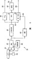
The block scheme of Fig. 1 has shown an additional modulation circuit of CD original paper exposure device according to an embodiment of the invention.
The block scheme of Fig. 2 has shown the disk original paper exposure device relevant with the additional modulation circuit of Fig. 1.
The block scheme of Fig. 3 has shown a 7T or the more testing circuit in the additional modulation circuit of Fig. 1.
Fig. 4 A to 4C is the skeleton view and the structural drawing of the CD that formed by the CD original paper exposure device among Fig. 2.
The block scheme of Fig. 5 has shown the optical media replication device of the CD that is used for reconstructed chart 4A to 4C.
The block scheme of Fig. 6 has shown second decoding scheme of the optical media replication device of Fig. 5.
The block scheme of Fig. 7 has shown that the M sequence of second decoding scheme among Fig. 6 produces circuit.
Embodiment
Below in conjunction with accompanying drawing embodiments of the invention are described in detail.
(1) structure of embodiment
The block scheme of Fig. 2 has shown CD original paper exposure device according to an embodiment of the invention, and according to CD original paper exposure device 1, to 2 exposures of CD original paper, and record is from the voice data SA of signal source 3 outputs.In making the step of CD, be used as CD original paper 2 after, handle by carrying out electroforming, forms a stamper, and on stamper mould of formation.In addition, in the step of making CD, constitute an optical disc substrate, above optical disc substrate, form one deck reflectance coating and layer protecting film, thereby form CD with the mould that forms by this way.
That is to say that according to CD original paper exposure device 1, spindle motor 4 drives 2 rotations of CD original paper, and exports the frequency generator signal FG that all raises at each predetermined rotary angle signal level from the base section of frequency generator (FG) signal generating circuit.Spindle servo circuit 5 drives spindle motor 4 so that the frequency of frequency generator signal FG becomes predetermined frequency, thereby drive CD original paper 2 with constant linear speed.
Laser instrument 6 is made of gas laser, the emission of lasering beam L1 CD original paper that exposes.
CD modulator 7 is the acousto-optical deflection devices (AOD) that are made of electroacoustic optical element or the like, be used to control light quantity by laser instrument 6 emitted laser bundles, this laser instrument is several to carry out ON/OFF control according to light modulating signal SD, thereby, and launch this laser beam by light modulating signal SD modulated laser light beam L1.
Catoptron 8 is launched photomodulator 7 emission laser beam L2 by optical channel of deflection.Object lens 9 focus on the reflected light of catoptron 8 on the protective seam surface of CD original paper 2.Catoptron 8 and object lens 9 move in the peripheral direction of CD original paper 2 synchronously continuously by a wire mechanism (not shown) and CD rotation, thereby shift the exposure position of laser beam L2 to the peripheral direction of CD original paper 2.
Therefore, according to CD original paper exposure device 1, when driving CD original paper 2 rotates, by mobile mirror 8 and object lens 9, form a spiral helicine track, and it is capable to form a groove according to voice data SA on track under constant linear speed.
According to the conventional optical disc original paper exposure device that is used to make CD, photomodulator 7 is directly driven by the 8-14 modulation signal EFM that produces by this way, according to the level of 8-14 modulation signal EFM, by the continuous exposure of the ON/OFF of laser beam L1 control to the CD original paper, thereby it is capable to form groove.
According to CD exposure device 1, in an additional modulation circuit 14, the subdata SB that 8-14 modulation signal EFM is exported by signal source 15 further modulates, and produces light modulating signal SD, thereby recording audio data SA not only on CD, and write down the second data SB.
Here, optical disc recognition code of signal source 15 outputs is as subdata SB.Optical disc recognition code SB is the data of history or the like of identification CD, comprise id information for example, the information relevant, control reproducible/not reproducible information or the like with manufacturer and date of manufacture, they be configured to each CD original paper intrinsic information.The optical disc recognition code of signal source 15 outputs 2 Bit datas comprises high-order b0 and low level b1.In addition, signal source 15 is exported optical disc recognition code SB with sub-code data SC as reference a long repetition period, that is to say, a block period of a time code in sub-code data SC constitutes the repetition period of optical disc recognition code SB.
Here, according to sub-code data SC, because a block period of time code is defined as 1/75 second by standard, therefore signal source 15 is with the optical disc recognition code SB of 75 bps output 1 bits, and for comprising whole optical disc recognition code SB of 2 bits, with 150 bps transmission speed output optical disc recognition code SB.
Under the CD situation, determine to adopt the linear speed record of 1.2 to 1.4m/ seconds by a standard.Therefore, when investigation 1.2m/ second during slow linear speed, signal source 15 output optical disc recognition code SB, like this, during track length in being converted to CD original paper 2, the track length of 16mm is corresponding to 1 optical disc recognition code SB.
Therefore, according to CD original paper exposure device 1, when on CD original paper 2 track length of a 16mm being arranged, the corresponding positions of optical disc recognition code SB can change a groove that has predetermined length in the zone by part and distribute and record.
For CD, the bit error that is produced by defective can carry out correction processing by error correction code being added to voice data.In addition, when the size of defective is bigger, bit error is difficult to timing, is eliminated or alters processing as the sound signal of duplicating the result.Under the CD situation, when occurring having predetermined length or longer defective, and this elimination or when altering the frequency gets higher of processing, Any user all can feel strange to the result who duplicates.That is to say that when predetermined length or longer defective occurring having, the commercial value of CD will be badly damaged.
That is to say, when the defect length of such grievous injury commercial value is represented with symbol L1, even when adopting error correction codes also correctly the defect length of replica audio signal being represented with symbol L2, constitute 16mm length with the optical disc recognition code SB distribution of 1 bit, make that the 16mm length remove L1 or L2 length respectively is exactly the length that optical disc recognition code SB can correctly duplicate with a predictive error rate in the recording/copying system of optical disc recognition code SB or littler value, will narrate in the back to this.
Therefore, according to CD exposure device 1, even when causing defective, when the voice data SA as master data can correctly be duplicated by error correction codes, and the voice data SA that constitutes master data can correctly be copied to the degree of the commercial value that guarantees CD, so that optical disc recognition code SB also can correctly be duplicated, optical disc recognition code SB is dispensed on the long distance scope on the CD so.But when big defective occurring, thereby when causing CD to lose commercial value, the optical disc recognition code just is difficult to be replicated.
In addition, according to CD original paper exposure device 1, even to the CD-ROM as the optical disc applications product, also set up mutual relationship, therefore, replaced by recording audio data SA and form CD, CD original paper exposure device 1 also can be used for forming CD-ROM.In addition, under the situation of CD-ROM, even the error correcting function of more having strengthened than CD by CD-ROM when bit error also is difficult to proofread and correct, the data of computer program and so on are difficult to correctly duplicate, commercial value also can suffer damage, thereby disk cognizance code SB also is difficult to duplicate.
In addition, reach when being difficult to correct copy cognizance code SB in the defective that causes, the length of 16mm is exactly the length that photodetector is enough to detect this defective.Thereby the defective that optical disc recognition code SB is difficult to correctly to be duplicated can be easy to be found by photodetector.
The block scheme of Fig. 1 has shown the detailed formation of additional modulation circuit 14.This additional modulation circuit 14 output 8-14 modulation signal EFM give PLL circuit (not shown), and duplicate the channel clock of 8-14 modulation signal EFM with the PLL circuit.Additional modulation circuit 14 provides the related circuit that has clock square frame, as the reference of handling 8-14 modulation signal EFM.
Synchronous detection signal SY of sync detection circuit 20 output distributes to the frame boundaries that the synchronizing signal of 8-14 modulation signal EFM is indicated 8-14 modulation signal EFM by detecting by a frame unit (588 channel clock-unit).In addition.Sync detection circuit 20 is by the border of time code code block detection time of distributing to 8-14 modulation signal EFM, and the piece sub-divided pulses signal on this border of output indication.Therefore, the bit boundary of piece sub-divided pulses signal BP indication CD cognizance code SB as mentioned above, and is exported in 98 frame periods by compact disk standards.
The M sequence produces circuit 21A and produces M sequence signal MA, and it is a random number of M sequence, this circuit with synchronous detection signal SY and piece division signals BP as a reference, and output M sequence signal MA.
That is to say, produce circuit 21A according to the M sequence, synchronous mode counting circuit 22 usefulness piece sub-divided pulses signal BP are the count value zero clearing, and to synchronous detection signal SY continuous counter.Here, for CD, constitute one with 98 frames, synchronous mode counting circuit 22 is exported from 0 to 97 count value continuously with piece sub-divided pulses signal BP property synchronizing cycle ground.
Initial value produces circuit 23 and is made of for example storer, and exports an initial value according to the count value of synchronous mode counting circuit 22.
M sequence counting circuit 24 has a series of continue continuous trigger and XOR circuit, and it gives trigger with the initial value that initial value produces circuit 23 outputs by the timing of synchronous detection signal SY.The channel clock synchronization of M sequence counting circuit 24 and 8-14 modulation signal EFM sends the content in the trigger continuously, thereby produces and output M sequence signal MA.Here, M sequence signal MA is a random number of M sequence, and is the signal that logical one and logical zero occur under equal possibility at random.
Therefore, the M sequence produces circuit 21A and constitutes binary number factor row generation device, be used at the other output of MA sequence signal MA scale-of-two factor row, and by operation synchronous mode counting circuit 22 and initial value produce circuit 23 with 8-14 modulation signal EFM in the constant cycle as a reference with the initialization of binary number factor row.
The computing difference in M sequence counting circuit 24, the formation that the M sequence produces circuit 21B is identical with the formation that the M sequence produces circuit 21A, M sequence generation circuit 21B produces the different M sequence signal MB of M sequence signal MA that produces circuit 21A output with the M sequence, and with its output.
That is to say, when the position of optical disc recognition code SB correspondence b0 is logical zero, XOR circuit 26A output M sequence signal MA itself, when position b0 is logical one, the M sequence signal of output counter-rotating.Therefore, XOR circuit 26A with M sequence signal MA disturb CD cognizance code SB than low level b0, and output should be than low level b0.Thereby XOR circuit 26A constitutes first countermeasure set, is used for by disturbing CD cognizance code SB to produce first undesired signal.Optical disc recognition code SB is the subdata that is produced the scale-of-two factor row of circuit 21A generation by the M sequence.
Similarly, when the position of optical disc recognition code SB correspondence b 1 is logical zero, XOR circuit 26B output M sequence signal MB itself, when position b1 is logical one, the M sequence signal of output counter-rotating.Therefore, XOR circuit 26B disturbs the high bit b1 of CD cognizance code SB with M sequence signal MB, and exports this high bit b1.Thereby XOR circuit 26B constitutes second countermeasure set, is used for by disturbing CD cognizance code SB to produce second undesired signal.Optical disc recognition code SB is the subdata that is produced the scale-of-two factor row of circuit 21B generation by the M sequence.
Random number generation circuit 27 produces random number signal (or quasi random number signal) RX by an arbitrary method, and exports this random number signal.Data selector 28 selects and exports the output signal of XOR circuit 26A and 26B according to the random number signal RX by random number generation circuit 27 outputs.Thereby additional modulation circuit 14 further disturbs and two b0 and the b1 of the compound optical disc recognition code that has been disturbed by M sequence signal MA and MB respectively, and produces a series of undesired signals.
Latch 29 latchs the also output signal of output data selector 28 in a moment of 8-14 modulation signal rising edge.Here, according to CD original paper exposure device 1, the rising edge of 8-14 modulation signal is by the starting time setting corresponding to the CD further groove, thereby, latch 29 latchs the also signal of output data selector 28 at this starting time, and the formation groove, and in cycle a period of time, keep this output signal, till a starting time in succession that forms groove.
The formation of 7T or longer testing circuit 30 as shown in Figure 3, it is in 7T or time cycle of rising corresponding to the one-period T detection signal level of the channel clock among the 8-14 modulation signal EFM in the time cycle in time limit longer time.Therefore, this 7T or longer testing circuit 30 detect the groove time that forms by corresponding to 2 last cycle of CD 7T or a longer length, and the output testing result is as detection pulse SX.
That is to say, 7T or EFM to 8 grade of trigger of longer testing circuit 30 input 8-14 modulation signals 31A to 31H, these triggers are connected to each other, and with the channel clock CK of 8-14 modulation signal EFM as reference consecutive transmissions 8-14 modulation signal EFM.In addition, this 7T or longer testing circuit 30 are input to the output signal of these triggers 31A to 31H and circuit 32.Here, in the end and the output signal that will reverse is input to and circuit 32 corresponding to trigger 31A counter-rotating and output signal the stage for 7T or longer testing circuit 30.
Therefore, when trigger 31H in the end the output signal in stage be logical zero, and other trigger 31A to 31G is when being logical one, this 7T or longer testing circuit 30 make the output signal with circuit 32 rise to logical one.Thereby, when the output signal with circuit 32 rises to logical one in this mode, this be after the signal level of 8-14 modulation signal EFM rises 7T or in longer time cycle this signal level continue a kind of situation of rising, therefore, detect the moment that forms groove in 7T or longer cycle.
This 7T or longer testing circuit 30 latch output signal with circuit 32 with latch 33, and the output latch result are as detecting pulse SX with channel clock CK as a reference.Therefore, signal level at 8-14 modulation signal EFM rises, and under the situation that the rising of this signal level continues to carry out in 7T or longer cycle, this detection pulse SX is output, so that signal level rose in the T time cycle of the channel clock CK of one-period.
Produce with circuit 34 (Fig. 1) and output is produced by the output signal of latch 29 and the pulse SX of signal and 7T or longer testing circuit 30.With from the signal triggering one shot multivibrator (MM) 35 of circuit 34 output, and the pulse signal RP that rises according to predetermined pulse width of output signal level.
In addition, according to present embodiment, be provided so that time that the signal level of output signal RP rises becomes from the starting point of 7T or longer time cycle the time delay of delay circuit 36 to begin through a time point after the time cycle of 3T.Therefore, according to additional modulation circuit 14, output signal RP is prevented with groove the 8-14 modulation signal EFM in capable that duplicating of voice data SA exerted an influence, and this 8-14 modulation signal EFM forms by the signal level that the output signal RP by one shot multivibrator 35 proofreaies and correct 8-14 modulation signal EFM.
Fig. 4 A to 4C is the skeleton view of the structural drawing of the CD that formed by CD original paper 2.As mentioned above, according to light modulating signal SD, when formation has a 7T or a more macrocyclic groove P1, by in the moment that is in groove P1 center basically, by pulse signal RP signal level is descended, under the situation of CD 40, in having 7T or more macrocyclic groove, the recess width of formation is narrowed near the central authorities of groove P1 according to M sequence signal MA and MB and optical disc recognition code SB.
Therefore, under the situation of CD 40, optical disc recognition code SB is recorded by the part change to groove, thereby the duplicating of data by the groove line item do not produced any influence, and write down the optical disc recognition code SB of 1 bit by the length of distributing an overlength, thereby, defect size not being influenced the situation that the master data of voice data is correctly duplicated, can correctly be duplicated as the optical disc recognition code of subdata.
In addition, according to CD 40, the optical disc recognition code SB of 2 bits is disturbed by random number signal RX, and corresponding bit-rows is further disturbed by M sequence signal MA and MB, therefore, the part with the groove P1 in 7T or longer cycle changes and is irregularly formed, thereby, according to the observation of microscope and so on device, the record of optical disc recognition code SB can be easy to be found.In addition, according to the observation to reproducing signals of the device of oscillograph and so on, this localized variation is counted as noise, therefore, by the waveform research to this reproducing signals, can find the record of optical disc recognition code SB at an easy rate.
The block scheme of Fig. 5 has shown the optical media replication device that is used to duplicate the CD 40 that forms by this way.According to optical media replication device 41, spindle motor 42 is controlled spindle servo circuit (not showing) by the clock that provides with CD 40 as reference, drives CD 40 and rotates with constant linear velocity.
Optical take-up apparatus H receives the light beam that returns with laser beam radiation CD 40 with predetermined light receiving element, and the reception result of light receiving element is carried out current/voltage-converted handle, and output light-receiving result.The light receiving signal of the 43 couples of optical take-up apparatus H of matrix circuit (MA) output carries out matrix computations to be handled, thereby tracking error signal TK that output signal level changes according to the tracking error amount according to the reproducing signals HF of capable changes of groove that forms on CD 40, signal level and signal level are according to the optically focused error signal FS of optically focused margin of error change.Therefore, optical take-up apparatus H and matrix circuit 43 have constituted the reproducing signals generation device, are used to receive the light beam that returns, and the generation signal level is capable according to groove or the reproducing signals HF of the capable change of mark.
Binary arithmetic circuit 45 usefulness predetermined threshold value are carried out the scale-of-two processing to the signal that duplicates, and output is as the signal BD of scale-of-two result.PLL circuit 46, duplicates and output channel clock CK as with reference to operation with scale-of-two processing signals BD.
Decoding scheme 47 duplicates and exports voice data and error correction codes by the groove line item by continuing as a reference to handle scale-of-two processing signals BD with channel clock CK.The data of 48 pairs of code translators of ECC circuit, 47 outputs are carried out treatment for correcting, duplicate and export the voice data SA of groove line item thus.Therefore, scale-of-two treatment circuit 45, PLL circuit 46 and decoding scheme 47 have constituted main code translator, are used for deciphering voice data SA as master data by the signal that identification is replicated.
A/D conversion circuit (AD) 49 usefulness channel clock CK carry out analog/digital conversion to the signal HF that duplicates as a reference, thereby output comprises 8 digitizing reproducing signals DX.Thereby A/D conversion circuit 49 constitutes sampling apparatus, be used for reproducing signals HF is sampled, and output is as the digitizing reproducing signals DX of sampled signal.
The block scheme of Fig. 6 has shown second decoding scheme 50.According to this second decoding scheme 50, subcode testing circuit 51 usefulness channel clocks latch and handle binary signal BD, thereby detect sub-code data by binary signal BD.In addition, subcode testing circuit 51 from the sub-code data that detects detection time code block boundary, and the piece editing pulse signal on this border of output indication.Thereby piece editing pulse signal BP indication is included in the bit boundary of the optical disc recognition code SB among the signal HF that duplicates.
The M sequence produces circuit (M sequence) 53A and 53B produces and export M sequence signal MA and MB respectively, they with recording operation in used identical among the interference CD cognizance code SB.That is to say, as shown in Figure 7, produce circuit A according to the M sequence, interpolation circuit 54 is counted channel clock CK as a reference with synchronous detection signal SY synchronously, thereby produce and export a synchronous detection signal SY2, even thereby be not when detecting with the synchronous detection signal at synchronous detection signal SY by counting clock frequency CK by a defective, also can correctly indicate the frame boundaries among the binary signal SY.
Therefore, concerning CD, by being provided with to 588 channel clocks as 1 frame in insertion cycle of synchronous detection signal SY, inserting circuit 54 synchronously utilizes this relation to produce synchronous detection signal SY2, thereby export this synchronous detection signal SY2, be used for synchronous detection signal SY by the situation of error-detecting under, even when synchronous detection signal SY is not come out by defects detection, also can correctly indicate frame boundaries.
Synchronous mode counting circuit 55 usefulness piece editing pulse signal BP are the count value zero clearing, and synchronous detection signal SY is counted in succession.Here, concerning CD, 1 comprises 98 frames, and therefore, synchronous mode counting circuit 55 from 0 to 97 repeats to export count value in the cycle of piece editing pulse signal BP, similar with the synchronous mode counting circuit 22 (Fig. 1) in the recording operation.
Initial value produces circuit 56 and is made of for example memory IC, and its keeps producing the identical content of circuit 23 with the initial value of record side, and exports an initial value according to the count value of synchronous mode counting circuit 55.
M sequence counting circuit 63 is identical with the M sequence counting circuit 24 of record side, is made of interconnected trigger and XOR circuit, in the time of sync detection circuit SY the initial value that initial value produces circuit 56 outputs is provided with to these triggers.M sequence counting circuit 63 and channel clock CK synchronously continuously the transmission trigger from content, thereby the identical M sequence signal of value that produces in generation and output and the recording operation.
Therefore, when carrying out initialization generation M sequence signal MA with the frame period in this way, even PLL circuit 46 by CD 40 on approximately during the defective faulty operation of 1mm, M sequence signal MA also can be in correct moment initialization, as a result, in channel clock CK, produce the position slippage, thereby, with M sequence signal MA as a reference, optical disc recognition code SB is decoded and correct decode results can be provided.
In addition, the M sequence produces circuit 53B and produces circuit 21B corresponding to the M sequence in the recording operation, and the calculating operation difference in M sequence counting circuit 63, the formation that the M sequence produces circuit 53B is identical with M sequence generation circuit 53A, therefore, will no longer do detailed explanation at this to it.
7T or longer testing circuit 57 are corresponding to 7T in the recording operation or longer testing circuit 30, it exports a latch signal, its signal level only rise by the time cycle of 1 channel clock period T in a 7T or a more macrocyclic groove, the described cycle is with the channel clock as a reference, by determining the continuous signal level of binary signal BD, distribute by optical disc recognition code SB.Therefore, 7T or longer testing circuit 57 and the 7T that explains with reference to figure 3 or longer testing circuit 30 are identical, except binary signal BD is continued transmission to replace the 8-14 modulation signal EFM.
Wherein, first product value that is correctly reflected according to position b0 and M sequence signal MA, in 1 optical disc recognition code SB is used as a time cycle of a unit distribution, position b0 is multiplied each other by M sequence signal MA, and added up, thereby this first product value converges to a steady state value corresponding to the logic level of position b0.According to present embodiment, according to the logic level of M sequence signal MA, the polarity of the latch result by the output of conversion latch 58, MA multiplies each other with the M sequence signal.The and as a reference result who adds up is carried out binary value identification, thereby correct decoding position b0 to be worth 0.
In contrast, according to the signal that disturbs position b1 to produce by M sequence signal MA, because M sequence signal MA and MB are random numbers, logical zero wherein is identical with the possibility that logical one produces, in a constant time cycle, MA multiply by a b1 with the M sequence signal, and with product accumulation, this signal converges to 0 value gradually.That is to say that according to present embodiment, by according to the logic level transition of the M sequence signal MA polarity from the latch result of latch 58 outputs, by at a constant periodic accumulation, the information of position b1 converges to 0 value.
Output signal according to mlultiplying circuit 60A, wherein first and second product values repeat according to random number signal RX, after in the time cycle that 1 optical disc recognition code SB is assigned with, adding up, serve as with reference to carrying out binary value identification by contraposition b0 to be worth 0, low level b0 can correctly be deciphered.
Therefore, summation circuit 61A output represent a b0 logic level accumulation result, this can add up in the cycle of piece splitting signal BP by the product to mlultiplying circuit 60A and realize, determine circuit 62A according to the accumulation result of summation circuit 61A being carried out binary value identification with piece splitting signal BP 0 level as a reference, thus decoding and output optical disc recognition code SB than low level b0.
Similar with the processing at M sequence signal MA place, mlultiplying circuit 60B is according to the logic level that is produced the M sequence signal MB of circuit 53B generation by the M sequence, and conversion is by the polarity of the latch result of latch 58 outputs, and the output latch result.Here, according to the output result of the mlultiplying circuit that provides in this way, calculate the product of M sequence signal MB and latch result.
Therefore, summation circuit 61B adds up the result of product of product circuit 60B in the cycle of piece splitting signal BP, thereby the accumulation result of the logic level of position b1 is represented in output, determine that circuit 62B operates the accumulation result of 0 level summation circuit 61B as a reference with piece splitting signal BP, thus the high bit b1 of record and output optical disc recognition code SB.
(2) operation of embodiment
In the above in the formation of Miao Shuing, according to present embodiment structure CD 40 time, in CD original paper exposure device 1 (Fig. 2), according to the voice data SA from signal source 3 (this is a digital audio tape) output, the CD original paper is exposed in succession, forms stamper, after this, form CD 40 by stamper.
To 2 exposures of CD original paper the time, voice data SA is converted into 8-14 modulation signal EFM, and this is by carrying out the processing that adds error correction codes in ECC circuit 11, realizing in 8-14 modulation circuit 23 and sub-code data SC addition then.In addition, 8-14 modulation signal EFM is converted into drive signal SD in additional modulation circuit 14, and by driving photomodulator 7 by drive signal SD it is recorded on the CD original paper 2.Thus, repeat groove and space by the length that produces according to a fundamental length that multiply by with integer corresponding to the one-period of channel clock, voice data SA is recorded on the CD original paper 2.
When 8-14 modulation signal EFM was converted to drive signal SD, 8-14 modulation signal EFM switched signal level by the part and is converted into drive signal SD, thereby, during the groove that constitutes is capable, formed a groove with local narrow width on CD original paper 2.Therefore, recess width is modulated, and the subdata of optical disc recognition code is recorded on the CD original paper 2.
That is to say, according to CD original paper exposure device 1, comprise that 2 optical disc recognition code SB than low level b0 and high bit b1 is output, and 8-14 modulation signal EFM limit according to the optical disc recognition code by additional modulation circuit 144 modulation, thereby produced drive signal SD.
In this case, optical disc recognition code SB is exported according to the time code of being distributed to sub-code data SC by a long bit period, in this long bit period, 1 time code cycle among the sub-code data SC constitutes the repetition period of optical disc recognition code SB, thereby, in CD 40, have and distribute in the zone of 16mm course length and write down 1.
When the voice data SA as master data can correctly be duplicated by error correction codes, with when the voice data SA as master data can correctly be copied to the degree that guarantees the CD commercial value, the length of 16mm is that optical disc recognition code SB can correctly be duplicated length, therefore, optical disc recognition code SB can correctly be duplicated, and without duplicate record.
In addition, 16mm is that the size of working as defective makes correct copy code SB very at need, and defective also is enough to by the observed length of light viewer, thereby the defective that optical disc recognition code SB is difficult to correctly be replicated can be easy to be found by photodetector.
In more detail, according to CD original paper exposure device 1 (Fig. 1), two kinds of M sequence signal MA and MB have been formed, they are scale-of-two factor row that the M sequence produces circuit 21A and 21B, and in XOR circuit 26a and 26b, optical disc recognition code SB is disturbed respectively by M sequence signal MA and MB than low level b0 and high bit b1, subsequently by data selector 28 multipath transmission.In addition, in the 7T of additional modulation circuit 14 or longer testing circuit 30, from 8-14 modulation signal EFM, detect and have 7T or a more macrocyclic corresponding time of groove, and according to the result who detects this time, make the signal level of 8-14 modulation signal EFM pass through subtraction circuit 37, descending corresponding to about middle position with 7T or more macrocyclic groove by data selector 28 multipath transmission.Thereby optical disc recognition code SB is assigned with 1 in the track with 16mm length, is dispersed in the scope of 16mm, and gives record by the central part that change has a groove in 7T or longer cycle.
Concerning having a kind of so macrocyclic groove, when roughly when the recess width of central part is changed, concerning CD 40, the distance that is changed part to recess width from the final position of the start position of groove and groove is substantially equal to or greater than the diameter of the laser beam of radiation replicate run.Therefore, concerning CD 40, when groove is changed by the part by this way, when reproducing signals crosscut scale-of-two clipping level, the formation of groove can make anything not change, thereby optical disc recognition code SB can be recorded and carry out multipath transmission, duplicating of voice data do not produced any influence, and this voice data is the master data by the groove line item.
Therefore, according to the optical disc recognition code SB that writes down in this mode, by adopting two kinds of M sequence signal MA and MB to disturb and multipath transmission optical disc recognition code SB, optical disc recognition code SB is being irregularly formed by continuous recess by having in the part change that 7T or more macrocyclic groove form.Optical disc recognition code SB can do to such an extent that very difficultly find or detect by microscopical observation with to waveform research of reproducing signals like this.
In addition, by being handled as select two groups of undesired signals to carry out multipath transmission with reference to the random number signal RX that produces by random number generation circuit 27, the part that forms in groove changes and can be provided with very brokenly by continuous recess.Therefore, the record of this seed data can be done to such an extent that more be difficult to be found or detect.
Therefore, duplicating the limit, according to the result who detects the optical disc recognition code, irregular duplicating can be got rid of effectively, thereby copyright owner's right can be protected.
In addition, adopt common bootlegging method to be difficult to duplicate the local location of this groove shapes, therefore, therefore bootlegging also can be got rid of effectively.
In more detail, according to present embodiment, by the track length of 16mm being distributed to 1 optical disc recognition code SB, and by a time cycle can be set, the signal level of 8-14 modulation signal EFM is descended by one shot multivibrator 35, and optical disc recognition code SB can be duplicated definitely, and reduces the distortion of signal groove significantly, and the optical disc recognition code can do very difficult discovery and detecting, also be difficult to duplicate.
When disturbing M sequence signal MA and MB to come recording disk cognizance code SB in this mode, according to additional modulation circuit 14, in sync detection circuit 20, the frame boundaries of time code and block boundary are detected by 8-14 modulation signal EFM.In addition, with testing result as a reference, a frame unit that produces circuit 23 with initial value is provided with initial value to M sequence counting circuit 24, thereby this M sequence signal MA and MB are by the one-period initialization of this frame.
Therefore, duplicating the limit, producing similar M sequence signal MA and MB, when duplicating the optical disc recognition code SB by disturbance records,, also can eliminate in the very short time by the influence that this mistake produces even when so-called position slippage mistake in the channel clock, occurring.Therefore, being difficult to discovery and detected optical disc recognition code can be duplicated definitely.
That is to say that according to the CD 40 that is formed by CD original paper 2, in optical media replication device 41 (Fig. 5), the Returning beam that provides by the radiation laser light beam is the signal HF that is received and duplicates, its signal level is according to the capable change of groove.According to optical media replication device 41, reproducing signals HF is carried out scale-of-two and handles, and channel clock CK is replicated, and with channel clock CK as a reference, by handling decoding scheme 47 and ECC circuit 48, duplicates voice data SA.
In this case, concerning CD 40, because the part of groove changes by having 7T or more macrocyclic groove and forms at the substantial middle position of groove, the edge of the light beam spot swept notch of laser beam and recess width are in reformed position of different time, thereby, in the signal HF that is replicated, the influence that is reduced the recess width generation by the part can be avoided.That is to say,, prevented by the variation of the signal level that changes groove and produce at the adjacent zone of respective edges position for CD 40, thus can by with to the common laser phonograph identical processing duplicate voice data.
Concerning optical media replication device 41, in A/D conversion circuit 49, the signal HF that duplicates was sampled in the cycle of channel clock, produced digitized reproducing signals DX thus, and this signal is handled by second decoding scheme 50, thus copy cognizance code SB.According to optical media replication device 41,, for example, the processing of voice data SA is switched, thereby copyright owner's right can be effectively protected according to the result of copy cognizance code SB.
In the processing procedure of second decoding scheme 50 (Fig. 6), for 7T or longer testing circuit 57, by detect the signal level of the signal BD that carries out the scale-of-two processing continuously as reference with channel clock CK, with the detection type of record side seemingly, and have 7T or more macrocyclic groove time corresponding is detected.In addition, according to the result who detects, digital copy signal DX is latched to latch 58, and thus, digital copy signal DX was imported selectively with respect to the time of superposition optical disc recognition code SB.
In addition, in sync detection circuit 52; frame boundaries and block boundary produce among circuit 53A and the 53B in the M sequence and detect from binary signal BD, produce based on the result who detects frame boundaries and block boundary with M sequence signal similar M sequence signal MA and MB in the recording operation.In addition,, provide sum of products result of calculation, and this sum of products result of calculation is determined by definite circuit 62A and 62B with the digital copy signal DX that is input to latch 58 selectively respectively by two kinds of M sequence signal MA and MB.
According to optical media replication device 41,, repeat to handle, thereby optical disc recognition code SB is decoded in each 16mm length of having distributed 1 optical disc recognition code SB.Therefore, the sum of products result of calculation that the part of the groove that provides from the 16mm scope in this mode changes is provided, and its value is more much bigger than the random noise that is blended among the reproducing signals HF.Therefore, even when the change amount at corresponding recesses place is set to very little deflection, this change amount also can be duplicated definitely.
In addition, in replicate run, by using M sequence signal MA and MB to calculate sum of products result of calculation respectively, even when corresponding to the undesired signal of the low level b0 of M sequence signal MA and MB and high-order b1 by irregular arrangement multipath transmission, and the reference value that the decoding multipath transmission constitutes is not transferred to the side of duplicating from the side of decoding, low level b0 and high-order b1 also can correctly be deciphered.Therefore, the optical disc recognition code is done to such an extent that be difficult to be found, thereby can be duplicated definitely.
In this way, be used for deciphering the M sequence signal MA of optical disc recognition code SB and MB corresponding with recording operation respectively, and produced frame period initialization among circuit 53A and the 53B by the M sequence.Therefore, according to optical media replication device 41, interrupted by the defective of CD 40 even work as reproducing signals HF, thereby produce so-called position slippage mistake, M sequence signal MA and MB also can be proofreaied and correct rapidly, thereby can stop the error-detecting to optical disc recognition code SB.
(3) effect of embodiment
According to above-described formation, the situation that voice data SA as master data can correctly be duplicated to defect size, by the optical disc recognition code SB of record as subdata, make optical disc recognition code SB to give to have that predetermined length or longer groove are capable is correctly duplicated by the optical disc recognition code SB that distributes 1, when the optical disc recognition code is write down by the shape that is partly changed groove, the optical disc recognition code can be duplicated definitely, and without duplicate record optical disc recognition code.In addition, by distribute 1 in long scope, the part of groove shapes changes and can reduce, thereby optical disc recognition code SB can be difficult to be found, and duplicates and can be prevented, thereby has effectively prevented the bootlegging problem.
In addition, when defective causes 1 optical disc recognition code SB to be difficult to be replicated, because distributing the length of 1 optical disc recognition code SB is to observe the length that detects defective by light, concerning the CD that wherein optical disc recognition code can not correctly be duplicated, but be easy to be found, and the quality of CD can be improved.
In addition, by disturbing also recording disk cognizance code SB by M sequence signal MA and MB as scale-of-two factor row, the part that forms in groove changes can do to such an extent that be difficult to be found or detect, thereby can prevent bootlegging.
In addition, scale-of-two factor row is the scale-of-two factor row of M sequence, and therefore, this scale-of-two factor row is easy to form.
In addition, the corresponding positions of optical disc recognition code is disturbed by the M sequence signal MA of two sequences and MB respectively, and this corresponding positions is changed multipath transmission and record by the part by groove shapes then, and therefore, the optical disc recognition code can be done to such an extent that be difficult to be detected.
In addition, handle by adopting random number to carry out multipath transmission selectively, optical disc recognition code SB can further do to such an extent that be difficult to detect.
In addition, by carrying out the initialization of M sequence signal MA and MB, can prevent because of the error-detecting of slippage mistake in position to the optical disc recognition code by the frame period.
Therefore, by corresponding to the above-mentioned rule structure side of duplicating, can prevent bootlegging effectively, thereby copyright owner's right can be protected effectively.
(4) other embodiment
In addition, although according to above-described embodiment, described in the situation that is assigned to 16mm length as 1 optical disc recognition code of subdata, the present invention is not limited thereto, distributes 1 length can be set to meet the different length of different needs.In addition, after various investigation, it is found that defect influence can be avoided to 1mm or longer length especially by distributing 1 optical disc recognition code, although this depends on the tolerance level of the error rate of optical disc recognition code.
In addition, although according to above-described embodiment, described after the optical disc recognition code is disturbed by scale-of-two factor row and also further disturbed and multiplex situation by random number, but the present invention is not limited thereto, after the optical disc recognition data are disturbed by scale-of-two factor row, the optical disc recognition code also can selected simply and multipath transmission, and then, corresponding undesired signal can be come multipath transmission by the groove that distributes undesired signal to give to have predetermined length respectively.
In addition, although according to top embodiment, the optical disc recognition code of having described 2 is by multipath transmission and situation about being recorded, the present invention not merely limits to therewith, can also come the records series data by omitting the multipath transmission processing with 1 then according to some different positions of different situation multipath transmission.
In addition, although according to top embodiment, described having the situation of 7T or more macrocyclic groove modulation recess width and recording disk cognizance code, the present invention not merely limits to therewith, when dubbing system can guarantee enough to tolerate the vibration of reproducing signals, can select groove shapes can carry out the groove of multiple change as required, identical to the change of groove shapes when having 6T or more macrocyclic groove situation, under latter event, only the groove with predetermined length is just changed groove shapes.
In addition, although according to top embodiment, described by general who has surrendered's laser beam under the signal level that makes the 8-14 modulation signal and temporarily be controlled to be the situation that " pass " changes groove shapes, the present invention is not limited only to this, and groove shapes can also change by the light quantity that changes laser beam.Therefore, also can come the local width that increases groove, and the optical disc recognition code also can increase or reduce recess width by the part, decipher with 3 numerical value by changing groove shapes.In addition, also can be by progressively setting up the degree that increases or reduce, a plurality of numerals that are higher than 3 numerical value by record are come the recording disk cognizance code.
In addition, although according to top embodiment, described by changing the situation that groove shapes is come the recording disk cognizance code, the present invention is not limited only to this, and various data can be applicable to by changing the data of groove shapes record.That is to say that master data can be encrypted and record with groove is capable, can also write down the necessary data that is used to decipher by the shape that changes groove, thus, copyright owner's right can more effectively be protected.
In addition, although according to top embodiment, described and the situation of using the parallel synchronous recording subdata of groove line item master data, the present invention is not limited only to this, and this subdata can only be recorded in the specific region of CD.In addition, in this case, can consider subdata is recorded in the situation of reading in the zone.In addition, in these cases, in the zone that does not have recording sub-data at all, recess width also can change, and therefore, has write down a zone of subdata and can do to such an extent that be difficult to be found.
In addition, although according to top embodiment, described with definite circuit and determined the result of calculation of sum of products and the situation of copy cognizance code, the present invention is not limited only to this, can also extensively adopt Viterbi decoding or various recognition methods.
In addition, although according to top embodiment, adopt 8-14 to modulate the recording digital audio data, the present invention is not limited only to this, and it extensively is suitable for other various modulation, as 1-7 modulation, 8-16 modulation, 2-7 modulation or the like.
In addition, although according to top embodiment, described the data conditions by the requirement of groove line item, the present invention not merely limits to therewith, and it also is widely used in the data conditions with the requirement of mark line item.
In addition, although according to top embodiment, described the situation by radiation laser light beam exposure CD original paper, the present invention is not limited only to this, and it also is widely used in writing down by the radiating electron bundle data conditions of requirement.
In addition, although according to top embodiment, described the present invention is used for the situation that CD and external device come recording audio data, the present invention not merely limits to therewith, and it can also be widely used in various other CDs and external device, as the dish or the like of making video recording.
In addition, although according to top embodiment, the situation that the present invention is applied to optical disk system has been described, the present invention is not limited only to this, it also can be widely used in card-like information recording carrier, similar in its information recording surface and CD and the external device thereof.
Claims (8)
1. information recording carrier, wherein or mark line item capable by groove in the information recording carrier of master data, the defective that at least master data can correctly be duplicated to size, change groove a groove or a mark capable or that mark is capable by the part and come recording sub-data, and 1 of distributing subdata gives the groove with predetermined length capable or mark is capable, thereby subdata can correctly be duplicated, and wherein Yu Ding length is 1mm or a longer length.
2. information recording carrier according to claim 1 is characterized in that the length of being scheduled to is under the situation that causes 1 defective that is difficult to be replicated that makes subdata, the length that this defective can be observed by the light observation device.
3. information recording carrier according to claim 1 is characterized in that local the change is according to disturbing a undesired signal of subdata to form with scale-of-two factor row.
4. information recording carrier according to claim 3 is characterized in that scale-of-two factor row is a scale-of-two factor row of M sequence.
5. information recording carrier according to claim 3, it is characterized in that scale-of-two factor row comprises at least one first and one second scale-of-two factor row, undesired signal is disturbed first and second undesired signal of the capable generation of first and second grooves by adopting the first and second scale-of-two factor row respectively by subdata, and produce by multipath transmission first and second undesired signals.
6. information recording carrier according to claim 5 is characterized in that producing undesired signal thus by selecting first and second undesired signals according to a predetermined random number.
7. information recording carrier according to claim 3 is characterized in that scale-of-two factor row is capable and mark is capable is initialised a constant time cycle as a reference with groove.
8. information recording carrier according to claim 1 is characterized in that the encrypted and record of master data, and subdata is the necessary data of this master data of deciphering.
Applications Claiming Priority (3)
| Application Number | Priority Date | Filing Date | Title |
|---|---|---|---|
| JP199896/99 | 1999-07-14 | ||
| JP19989699A JP3292298B2 (en) | 1999-07-14 | 1999-07-14 | Information recording apparatus, information recording method, information recording medium, information reproducing apparatus, and information reproducing method |
| JP199896/1999 | 1999-07-14 |
Related Parent Applications (1)
| Application Number | Title | Priority Date | Filing Date |
|---|---|---|---|
| CNB001225812A Division CN1133981C (en) | 1999-07-14 | 2000-07-14 | Information recording equipment, information recording method, information recording media, information replication device and information replication method |
Publications (2)
| Publication Number | Publication Date |
|---|---|
| CN1516165A CN1516165A (en) | 2004-07-28 |
| CN100407319C true CN100407319C (en) | 2008-07-30 |
Family
ID=16415417
Family Applications (2)
| Application Number | Title | Priority Date | Filing Date |
|---|---|---|---|
| CNB001225812A Expired - Lifetime CN1133981C (en) | 1999-07-14 | 2000-07-14 | Information recording equipment, information recording method, information recording media, information replication device and information replication method |
| CN031386202A Expired - Lifetime CN100407319C (en) | 1999-07-14 | 2000-07-14 | Information recording device, information recording method and medium, information copy device and method |
Family Applications Before (1)
| Application Number | Title | Priority Date | Filing Date |
|---|---|---|---|
| CNB001225812A Expired - Lifetime CN1133981C (en) | 1999-07-14 | 2000-07-14 | Information recording equipment, information recording method, information recording media, information replication device and information replication method |
Country Status (11)
| Country | Link |
|---|---|
| US (4) | US6963529B1 (en) |
| EP (1) | EP1069563B1 (en) |
| JP (1) | JP3292298B2 (en) |
| KR (1) | KR100638774B1 (en) |
| CN (2) | CN1133981C (en) |
| AT (1) | ATE388469T1 (en) |
| DE (1) | DE60038210T2 (en) |
| ID (1) | ID27872A (en) |
| MY (1) | MY128358A (en) |
| SG (1) | SG86418A1 (en) |
| TW (1) | TW483000B (en) |
Families Citing this family (18)
| Publication number | Priority date | Publication date | Assignee | Title |
|---|---|---|---|---|
| JP3292298B2 (en) * | 1999-07-14 | 2002-06-17 | ソニー株式会社 | Information recording apparatus, information recording method, information recording medium, information reproducing apparatus, and information reproducing method |
| JP4310885B2 (en) | 2000-05-11 | 2009-08-12 | ソニー株式会社 | Optical disc apparatus, optical disc access method, and optical disc |
| WO2003036641A1 (en) * | 2001-10-25 | 2003-05-01 | Matsushita Electric Industrial Co., Ltd. | Optical disk recording method and optical disk reproducing method |
| EP1441343A4 (en) * | 2001-10-31 | 2008-07-16 | Sony Corp | Data recording method, recorder, and data reproducing method and device |
| JP3754917B2 (en) * | 2001-12-05 | 2006-03-15 | ソニー株式会社 | Data recording medium, data recording method and apparatus |
| AU2003234357B2 (en) * | 2002-05-30 | 2009-04-09 | Lg Electronics Inc. | High density optical disc and method for reproducing and recording data thereof |
| JP2004056432A (en) * | 2002-07-19 | 2004-02-19 | Sony Corp | Device and method for detecting synchronizing signal |
| JP3994834B2 (en) * | 2002-09-13 | 2007-10-24 | ソニー株式会社 | Information recording apparatus, information recording method, and optical recording medium |
| EP1553568B1 (en) * | 2002-10-18 | 2009-08-26 | Panasonic Corporation | Information recording medium, information recording device, and information reproduction device for the same |
| EP1581933B1 (en) * | 2002-12-30 | 2008-01-23 | Koninklijke Philips Electronics N.V. | Additional data channel in between marks |
| JP4139801B2 (en) * | 2003-09-11 | 2008-08-27 | シャープ株式会社 | Information recording medium reproducing apparatus and information recording medium reproducing method |
| JP3988052B2 (en) * | 2004-01-29 | 2007-10-10 | ソニー株式会社 | Optical disc recording device, optical disc recording method, optical disc, optical disc playback device, and optical disc playback method |
| EP1756809B1 (en) * | 2004-06-03 | 2008-06-18 | Koninklijke Philips Electronics N.V. | Record carrier with improved modulation and asymmetry |
| JP4453567B2 (en) * | 2005-02-09 | 2010-04-21 | ソニー株式会社 | Recording apparatus, recording method, and disc manufacturing method |
| US7974170B2 (en) * | 2007-01-12 | 2011-07-05 | The Arizona Board Of Regents On Behalf Of The University Of Arizona | Application of wavelet transform filtering for processing data signals from optical data storage devices |
| JP2009187634A (en) * | 2008-02-07 | 2009-08-20 | Sony Corp | Optical disk recording device and method, optical disk and its reproducing device |
| CN106060527B (en) * | 2016-08-01 | 2018-10-19 | 北京小鸟看看科技有限公司 | A kind of method and apparatus of extension binocular camera orientation range |
| CN108536423B (en) * | 2017-03-03 | 2022-05-10 | 群联电子股份有限公司 | Random data generation circuit, memory storage device and random data generation method |
Citations (3)
| Publication number | Priority date | Publication date | Assignee | Title |
|---|---|---|---|---|
| EP0545472A1 (en) * | 1991-12-02 | 1993-06-09 | Koninklijke Philips Electronics N.V. | Closed information system with physical copy protection |
| EP0866454A2 (en) * | 1997-03-19 | 1998-09-23 | Sony Corporation | Recording apparatus, reproducing apparatus and optical recording medium |
| JPH11185258A (en) * | 1997-12-18 | 1999-07-09 | Sony Corp | Optical disk recording device, optical disk recording method, optical disk and optical disk reproducing device |
Family Cites Families (19)
| Publication number | Priority date | Publication date | Assignee | Title |
|---|---|---|---|---|
| JPS6230435A (en) * | 1985-07-31 | 1987-02-09 | Matsushita Electric Ind Co Ltd | Multiplexing method |
| JPH02252334A (en) * | 1989-03-27 | 1990-10-11 | Sony Corp | Selective scramble circuit |
| CA2108457A1 (en) | 1992-02-14 | 1993-08-15 | Seiji Kobayashi | Information recording medium, information recording apparatus, information reproducing apparatus and information recording and reproducing apparatus |
| JP2776209B2 (en) * | 1993-07-22 | 1998-07-16 | 日本ビクター株式会社 | Optical disc and information recording / reproducing device |
| BR9405444A (en) * | 1993-07-28 | 1999-09-08 | Sega Enterprises Kk | Information storage medium and electronic device that uses the same |
| JP2927163B2 (en) * | 1993-11-30 | 1999-07-28 | 日本ビクター株式会社 | Information signal recording method and information signal recording device |
| TW309612B (en) | 1994-09-22 | 1997-07-01 | Nippon Bickter Kk | |
| JPH08273201A (en) * | 1995-03-29 | 1996-10-18 | Toshiba Corp | Optical disk |
| MX9707795A (en) * | 1995-04-10 | 1997-12-31 | Matsushita Electric Ind Co Ltd | Optical record carrier and method for recording and reproducing signals therefrom. |
| DE69610860T2 (en) * | 1995-10-09 | 2001-03-15 | Matsushita Electric Ind Co Ltd | Optical disc that carries information in the form of a bar code |
| JP3852498B2 (en) * | 1997-03-21 | 2006-11-29 | ソニー株式会社 | Information recording apparatus, information reproducing apparatus, and information recording medium |
| JP3551727B2 (en) * | 1997-10-21 | 2004-08-11 | ソニー株式会社 | Optical information recording device, optical information recording medium, and optical information reproducing device |
| US6587948B1 (en) * | 1998-02-13 | 2003-07-01 | Sony Corporation | Recording apparatus, recording medium, playback apparatus, recording method and playback method |
| JP3520774B2 (en) | 1998-08-12 | 2004-04-19 | ソニー株式会社 | Optical disk reproducing apparatus and optical disk reproducing method |
| JP4292434B2 (en) * | 1999-03-30 | 2009-07-08 | ソニー株式会社 | Optical disc, optical disc recording apparatus, optical disc recording method, optical disc reproducing device, and optical disc reproducing method |
| JP3292298B2 (en) * | 1999-07-14 | 2002-06-17 | ソニー株式会社 | Information recording apparatus, information recording method, information recording medium, information reproducing apparatus, and information reproducing method |
| JP2001060340A (en) * | 1999-08-23 | 2001-03-06 | Toshiba Emi Ltd | Optical information recording medium with visual water mark, visual water mark forming device and its formation |
| US7362671B2 (en) * | 2001-08-13 | 2008-04-22 | Sony Corporation | Optical disc recording and/or playing apparatus and method |
| JP4003691B2 (en) * | 2002-11-15 | 2007-11-07 | ヤマハ株式会社 | Visible image forming method, program, and visible image forming system |
-
1999
- 1999-07-14 JP JP19989699A patent/JP3292298B2/en not_active Expired - Lifetime
-
2000
- 2000-07-07 US US09/611,597 patent/US6963529B1/en not_active Expired - Lifetime
- 2000-07-10 SG SG200003826A patent/SG86418A1/en unknown
- 2000-07-13 ID IDP20000591D patent/ID27872A/en unknown
- 2000-07-13 KR KR1020000040169A patent/KR100638774B1/en active IP Right Grant
- 2000-07-13 TW TW089113954A patent/TW483000B/en not_active IP Right Cessation
- 2000-07-13 MY MYPI20003203A patent/MY128358A/en unknown
- 2000-07-14 AT AT00115306T patent/ATE388469T1/en active
- 2000-07-14 CN CNB001225812A patent/CN1133981C/en not_active Expired - Lifetime
- 2000-07-14 CN CN031386202A patent/CN100407319C/en not_active Expired - Lifetime
- 2000-07-14 DE DE60038210T patent/DE60038210T2/en not_active Expired - Lifetime
- 2000-07-14 EP EP00115306A patent/EP1069563B1/en not_active Expired - Lifetime
-
2004
- 2004-08-26 US US10/926,049 patent/US7177255B2/en not_active Expired - Lifetime
-
2005
- 2005-04-14 US US11/105,380 patent/US7061851B2/en not_active Expired - Lifetime
- 2005-04-14 US US11/105,406 patent/US7068580B2/en not_active Expired - Lifetime
Patent Citations (3)
| Publication number | Priority date | Publication date | Assignee | Title |
|---|---|---|---|---|
| EP0545472A1 (en) * | 1991-12-02 | 1993-06-09 | Koninklijke Philips Electronics N.V. | Closed information system with physical copy protection |
| EP0866454A2 (en) * | 1997-03-19 | 1998-09-23 | Sony Corporation | Recording apparatus, reproducing apparatus and optical recording medium |
| JPH11185258A (en) * | 1997-12-18 | 1999-07-09 | Sony Corp | Optical disk recording device, optical disk recording method, optical disk and optical disk reproducing device |
Also Published As
| Publication number | Publication date |
|---|---|
| DE60038210D1 (en) | 2008-04-17 |
| DE60038210T2 (en) | 2009-03-19 |
| CN1516165A (en) | 2004-07-28 |
| SG86418A1 (en) | 2002-02-19 |
| US20050018594A1 (en) | 2005-01-27 |
| EP1069563A2 (en) | 2001-01-17 |
| CN1133981C (en) | 2004-01-07 |
| EP1069563A3 (en) | 2003-12-10 |
| KR20010015323A (en) | 2001-02-26 |
| JP3292298B2 (en) | 2002-06-17 |
| US20050185543A1 (en) | 2005-08-25 |
| KR100638774B1 (en) | 2006-10-27 |
| MY128358A (en) | 2007-01-31 |
| ATE388469T1 (en) | 2008-03-15 |
| US20050180290A1 (en) | 2005-08-18 |
| US6963529B1 (en) | 2005-11-08 |
| EP1069563B1 (en) | 2008-03-05 |
| ID27872A (en) | 2001-04-26 |
| CN1281213A (en) | 2001-01-24 |
| JP2001028128A (en) | 2001-01-30 |
| US7061851B2 (en) | 2006-06-13 |
| US7068580B2 (en) | 2006-06-27 |
| TW483000B (en) | 2002-04-11 |
| US7177255B2 (en) | 2007-02-13 |
Similar Documents
| Publication | Publication Date | Title |
|---|---|---|
| CN100407319C (en) | Information recording device, information recording method and medium, information copy device and method | |
| KR100551234B1 (en) | Recorder | |
| US6587948B1 (en) | Recording apparatus, recording medium, playback apparatus, recording method and playback method | |
| US7035181B2 (en) | Apparatus and associated methodology of imparting content protection to optically recorded data for secure reproduction | |
| CN100550154C (en) | The data record method of recording medium | |
| US5703858A (en) | System for encoding a glass master to enable detection of a counterfeit optical CD-ROM | |
| CA2316959C (en) | Method and apparatus for determining the provenance of a data carrying disc | |
| EP1475788B1 (en) | Mastering device, disc manufacturing method, disc-shaped recording medium, disc reproduction device, and disc reproduction method | |
| CN100433138C (en) | CD device, CD recording method and compact discs | |
| JP2000195049A (en) | Optical disc recording apparatus and method, optical disk reproducing apparatus and method, and optical disk | |
| JP3292295B2 (en) | Optical disk recording device, optical disk recording method, optical disk, optical disk reproducing device | |
| US6219322B1 (en) | Optical information recording apparatus, optical information recording method, optical information recording medium and optical information reproducing apparatus | |
| JP4310885B2 (en) | Optical disc apparatus, optical disc access method, and optical disc | |
| JPWO2004029943A1 (en) | Optical recording medium and optical recording medium recording apparatus | |
| US20060187793A1 (en) | Optical disc recording apparatus, optical disc recording method, optical disc, optical disc reproducing apparatus, and optical disc reproducing method | |
| JPH11126425A (en) | Optical disk device, optical disk reproducing method and optical disk | |
| KR20050060095A (en) | Recording medium dedicated to reproduction | |
| JP4442692B2 (en) | Optical disc apparatus, optical disc recording method, optical disc, optical disc reproduction method, optical disc reproduction device, processing device, and modulation device | |
| KR100656687B1 (en) | Optical disk recording apparatus and method, and optical disk | |
| JPH09265668A (en) | Optical recording medium and optical drive device |
Legal Events
| Date | Code | Title | Description |
|---|---|---|---|
| C06 | Publication | ||
| PB01 | Publication | ||
| C10 | Entry into substantive examination | ||
| SE01 | Entry into force of request for substantive examination | ||
| C14 | Grant of patent or utility model | ||
| GR01 | Patent grant | ||
| CX01 | Expiry of patent term |
Granted publication date: 20080730 |
|
| CX01 | Expiry of patent term |