CN100385812C - Multipath propagation delay determination means using periodically inserted pilot symbols - Google Patents
Multipath propagation delay determination means using periodically inserted pilot symbols Download PDFInfo
- Publication number
- CN100385812C CN100385812C CNB998092304A CN99809230A CN100385812C CN 100385812 C CN100385812 C CN 100385812C CN B998092304 A CNB998092304 A CN B998092304A CN 99809230 A CN99809230 A CN 99809230A CN 100385812 C CN100385812 C CN 100385812C
- Authority
- CN
- China
- Prior art keywords
- delay
- sector
- spectrum
- cdma
- power
- Prior art date
- Legal status (The legal status is an assumption and is not a legal conclusion. Google has not performed a legal analysis and makes no representation as to the accuracy of the status listed.)
- Expired - Fee Related
Links
Images


Classifications
-
- H—ELECTRICITY
- H04—ELECTRIC COMMUNICATION TECHNIQUE
- H04W—WIRELESS COMMUNICATION NETWORKS
- H04W24/00—Supervisory, monitoring or testing arrangements
-
- H—ELECTRICITY
- H04—ELECTRIC COMMUNICATION TECHNIQUE
- H04B—TRANSMISSION
- H04B1/00—Details of transmission systems, not covered by a single one of groups H04B3/00 - H04B13/00; Details of transmission systems not characterised by the medium used for transmission
- H04B1/69—Spread spectrum techniques
- H04B1/707—Spread spectrum techniques using direct sequence modulation
- H04B1/7073—Synchronisation aspects
- H04B1/7075—Synchronisation aspects with code phase acquisition
- H04B1/70754—Setting of search window, i.e. range of code offsets to be searched
-
- H—ELECTRICITY
- H04—ELECTRIC COMMUNICATION TECHNIQUE
- H04B—TRANSMISSION
- H04B1/00—Details of transmission systems, not covered by a single one of groups H04B3/00 - H04B13/00; Details of transmission systems not characterised by the medium used for transmission
- H04B1/69—Spread spectrum techniques
- H04B1/707—Spread spectrum techniques using direct sequence modulation
- H04B1/7097—Interference-related aspects
- H04B1/711—Interference-related aspects the interference being multi-path interference
- H04B1/7113—Determination of path profile
-
- H—ELECTRICITY
- H04—ELECTRIC COMMUNICATION TECHNIQUE
- H04B—TRANSMISSION
- H04B1/00—Details of transmission systems, not covered by a single one of groups H04B3/00 - H04B13/00; Details of transmission systems not characterised by the medium used for transmission
- H04B1/69—Spread spectrum techniques
- H04B1/707—Spread spectrum techniques using direct sequence modulation
- H04B1/7097—Interference-related aspects
- H04B1/711—Interference-related aspects the interference being multi-path interference
- H04B1/7115—Constructive combining of multi-path signals, i.e. RAKE receivers
-
- H—ELECTRICITY
- H04—ELECTRIC COMMUNICATION TECHNIQUE
- H04B—TRANSMISSION
- H04B1/00—Details of transmission systems, not covered by a single one of groups H04B3/00 - H04B13/00; Details of transmission systems not characterised by the medium used for transmission
- H04B1/69—Spread spectrum techniques
- H04B1/707—Spread spectrum techniques using direct sequence modulation
- H04B1/7073—Synchronisation aspects
- H04B1/7075—Synchronisation aspects with code phase acquisition
- H04B1/70755—Setting of lock conditions, e.g. threshold
-
- H—ELECTRICITY
- H04—ELECTRIC COMMUNICATION TECHNIQUE
- H04B—TRANSMISSION
- H04B1/00—Details of transmission systems, not covered by a single one of groups H04B3/00 - H04B13/00; Details of transmission systems not characterised by the medium used for transmission
- H04B1/69—Spread spectrum techniques
- H04B1/707—Spread spectrum techniques using direct sequence modulation
- H04B1/7097—Interference-related aspects
- H04B1/711—Interference-related aspects the interference being multi-path interference
- H04B1/7115—Constructive combining of multi-path signals, i.e. RAKE receivers
- H04B1/7117—Selection, re-selection, allocation or re-allocation of paths to fingers, e.g. timing offset control of allocated fingers
-
- H—ELECTRICITY
- H04—ELECTRIC COMMUNICATION TECHNIQUE
- H04B—TRANSMISSION
- H04B2201/00—Indexing scheme relating to details of transmission systems not covered by a single group of H04B3/00 - H04B13/00
- H04B2201/69—Orthogonal indexing scheme relating to spread spectrum techniques in general
- H04B2201/707—Orthogonal indexing scheme relating to spread spectrum techniques in general relating to direct sequence modulation
- H04B2201/70701—Orthogonal indexing scheme relating to spread spectrum techniques in general relating to direct sequence modulation featuring pilot assisted reception
-
- H—ELECTRICITY
- H04—ELECTRIC COMMUNICATION TECHNIQUE
- H04B—TRANSMISSION
- H04B2201/00—Indexing scheme relating to details of transmission systems not covered by a single group of H04B3/00 - H04B13/00
- H04B2201/69—Orthogonal indexing scheme relating to spread spectrum techniques in general
- H04B2201/707—Orthogonal indexing scheme relating to spread spectrum techniques in general relating to direct sequence modulation
- H04B2201/70702—Intercell-related aspects
-
- H—ELECTRICITY
- H04—ELECTRIC COMMUNICATION TECHNIQUE
- H04W—WIRELESS COMMUNICATION NETWORKS
- H04W4/00—Services specially adapted for wireless communication networks; Facilities therefor
- H04W4/18—Information format or content conversion, e.g. adaptation by the network of the transmitted or received information for the purpose of wireless delivery to users or terminals
-
- H—ELECTRICITY
- H04—ELECTRIC COMMUNICATION TECHNIQUE
- H04W—WIRELESS COMMUNICATION NETWORKS
- H04W48/00—Access restriction; Network selection; Access point selection
- H04W48/16—Discovering, processing access restriction or access information
-
- H—ELECTRICITY
- H04—ELECTRIC COMMUNICATION TECHNIQUE
- H04W—WIRELESS COMMUNICATION NETWORKS
- H04W64/00—Locating users or terminals or network equipment for network management purposes, e.g. mobility management
- H04W64/006—Locating users or terminals or network equipment for network management purposes, e.g. mobility management with additional information processing, e.g. for direction or speed determination
-
- H—ELECTRICITY
- H04—ELECTRIC COMMUNICATION TECHNIQUE
- H04W—WIRELESS COMMUNICATION NETWORKS
- H04W88/00—Devices specially adapted for wireless communication networks, e.g. terminals, base stations or access point devices
- H04W88/08—Access point devices
Abstract
A multipath propagation delay determining means (STU) for determining a power delay spectrum (DPS) of a signal on a plurality of propagation paths within a cell of a CDMA communication system, comprising A/D conversion means for converting a CDMA multipath signal received from at least one antenna (Ant1, Ant2) into a signal (S1, S2) consisting of consecutive radio frames including consecutive time slots with complex pilot symbols and data symbols, demultiplexing means for extracting complex pilot symbols and data symbols from at least two consecutive time slots of each radio frame and for storing them consecutively in memory means; and a searching means (S1...SL) for determining a power delay profile (DPS) on the basis of said extracted and stored complex pilot symbols and said data symbols.
Description
Invention field
The present invention relates to a kind of multipath transmisstion and postpone to determine device, it is used in particular for a cdma base station, and wherein the frequency pilot sign that periodically comprises in the radiofrequency signal frame can be used for effective power-delay spectrum (profile) calculating and improved Path selection, tracking and sector selection.
Specifically, invention relates to use so-called RAKE (Rake) receiver realization above-mentioned functions.
Background of invention
Code division multiple access access (CDMA) based on direct sequence (DS) spread spectrum (SS) technology is that third generation broadband cellular mobile communication system is (for example in UMTS, as the people such as IMT-2000:J.E.Puget that describe in the list of references [1]: " wireless personal communications outline ", the ieee communication magazine, January nineteen ninety-five, 28-41 page or leaf) a kind of candidate technologies that is expected to use.
As shown in Figure 1, be that the area that several mobile station MSs 1, MS2...MS serve can be regarded as a cdma communication system sub-district by (a fixing) base station BS.Certified is that the DS-SS CDMA technology can the transmitting high speed data signal, (list of references [2]: people's such as A.Baier: " based on the design studies of the third generation mobile radio system of CDMA " in RACE CODIT project for example, the ieee communication monograph, the 12nd volume, in May, 1994, the 733-743 page or leaf).DS-SS-CDMA is in commercial system, for example based on using (D.P.Whipple: " CDMA standard ", microwave and wireless application, in December, 1994,24-37 page or leaf) in the system of IS ' 95.Equally, Japan also drops into greatly the DS-SS-CDMA system.
Although the CDMA mode has implied some fundamental characteristics of cdma receiver and cdma communication system, but the specific implementation for despreading device, searcher and path selection unit also studied in great detail up to now, because also do not determine the standard of W-CDMA at present.What therefore, the present invention relates to is the specific implementation of the essential individual unit of cdma receiver.Because cdma base station of the present invention, CDMA receive mode and cdma system are actually the CDMA technology based on DS-SS, so the basic fundamental (also can referring to based reference [4]: A.J.Viterbi: " CDMA: spread spectrum communication theory; publication; MA:Adison-Wesley, 1995 ") of DS-SS CDMA transmission hereinafter will be discussed.
DE 19506117C1 has described a kind of method that is used to estimate the transmission channel impulse response, and this Channel Transmission is pressed CDMA mode information encoded.Information by a spreading code spread spectrum, is passed through the associated code despreading of a correspondence in transmitter one side in receiver one side.The transient change of propagation path is considered at receiving terminal.
DE 19615257A1 has described a kind of CDMA-RAKE receiver with sub-chip resolution.This receiver is applicable to the DS-CDMA communication system.It comprises a channel estimating apparatus, can decompose the multipath component less than single chip-spaced.
The CDMA technology basis
Basically, in CDMA technology, by spread spectrum, therefore shown in Fig. 2 a, the output signal O of generation has the bandwidth more much bigger than input signal I to the input signal I of limited bandwidth (transmission rate) by the much bigger predetermined frequency expansion sequence (PN sequence) of bandwidth.Because all signals of discussing in the CDMA technology all are digital signals, so spreading rate is in fact being represented in the expression of " bandwidth ".
Shown in Fig. 2 b, in the CDMA mode of using the QPSK modulation, two digital signal bit constitute a symbol.Each bit in this symbol all will be subjected to the spread spectrum of PN sequence, and spread-spectrum signal (lower curve among Fig. 2 b) is made up of one group " chip ", and chip is defined as a 0-in the despread signal〉1 and 1-0 (or 1-〉0 and 0-1) part.
Shown in Fig. 2 a, defined a so-called spreading gain M who equals the ratio of spreading rate and character rate.In fact M has represented spread spectrum coefficient, promptly bandwidth since the spread spectrum of PN sequence and broadening what.Certainly, because all signals all are digital, so the PN sequence also is a digital signal (being made up of some bits).
If in cdma receiver, recover primary signal I, need in the despreading device DSP shown in Fig. 2 a, carry out despreading certainly and handle, wherein multiply each other by the used original PN sequence of spread-spectrum signal (sequence 0) and spread processing, obtain raw information.
But, as shown in Figure 3, all information in the CDMA Channel all send in chronological order, promptly according to continuous radio frequency frame RFn.This means that spread spectrum and despreading also must carry out frame by frame.In transmitter, each frame is according to frequency expansion sequence (PN sequence) spread spectrum that begins from frame starting point, and this also means the despreading that must carry out with time synchronized (being to align the time) in receiver certainly, i.e. despreading sequence must be alignd with the starting point of received frame.Yes for the PN sequence to an all known sequence of transmitter and receiver, but must carry out the time unifying by group (M) synthetic (despreading) in receiver.
The basic principle of a base station receiver as shown in Figure 4.As can be seen from Figure 4, demodulator DEMOD receives the input from PN generator PN-GEN (producing PN despreading sequence) and timing control unit TCU.In theory, be input from the signal of different antennae Ant0, the Ant1 of different sector 1...6 to automatic gain control circuit AGC, output sampling is the input to the so-called searcher S (its function will be described below) that calculates (power) delay spectrum.The bit sequence of demodulator DEMOD (comprising the so-called RAKE receiver that below will explain in detail) after decoder DEC output demodulation expands.Shown in the back, in fact searcher S comprises a search and a tracking cell (the sub-district part shown in Fig. 1,12) for serving from the input signal of all sectors.The output of searcher S is length of delay and (sector) selection information.
Searcher S comprises that also the reason of a tracking cell is because the multipath transmisstion problem, it be any mobile communication system an intrinsic specific character.Therefore, will explain the multipath transmisstion that is associated with the tracking characteristics of cdma system below.
The CDMA multipath transmisstion
As shown in Figure 5, between mobile station MS and base station BS, directapath P1 is arranged not only, also has indirect path P2, P3, for example since building H, automobile C or mountain range M reflection produced.This mixing (being multipath transmisstion) direct and indirect path means that received signal energy (being the power of each transmitting sequence sampling) does not have constant time delay (corresponding with the light velocity).This means t
0A sampling (bit) that sends is at t constantly
1Constantly arrive base station BS, another part energy then since energy along the further propagation of indirect path P2 or P3 at moment t
2Arrive base station BS.This has just produced the delay spectrum of each sampling as shown in Figure 5.That is to say that each sampling is expanded, and is characterized by (decline) individual paths usually on delay spectrum.Therefore, the time difference t among Fig. 5
1-t
0, t
2-t
0Deng being defined as postponing d
1, d
2Deng.
In traditional DS-SS-CDMA technology, the multipath transmisstion problem is solved by the so-called RAKE receiver of describing in above-mentioned list of references [2] and [3] usually.The basic principle of RAKE receiver is not only from directapath P1, also will collect the energy of each symbol from one group of indirect path P2, P3.RAKE receiver generally will be distributed " mark " (in CDMA, this mark is called as " branch road ") for individual paths (being maximum) the strongest in the respective signal delays spectrum.Then, energy that every paths is collected or information separately by path (being each RAKE branch road) carry out demodulation/detection.Information after the demodulation is merged again, for example according to the high specific technology.Also disclosed shown in Fig. 6 right side among EP 0 776 105A1, be used to receive a kind of RAKE receiver of search and tracking cell output.Here, in a matched filter, the storage received signal that is provided is carried out despreading.Despread signal is sent to delay cell, channel estimator and pilot frame synchronizer.Channel estimator extracts a frequency pilot sign that its form is known from despread signal, estimate phase change by the pilot signal that relatively this frequency pilot sign and pilot signal generator provide.The phase change that channel estimator is estimated is converted into a signal, and sends interpolater and extrapolator to.For the information symbol in the pilot group, the locational estimated value of each information symbol that estimates in the pilot both sides is used to estimate the channel variation of each information symbol.On the other hand, for the information symbol outside the pilot group, estimate to be confirmed as the channel variation estimated value near the channel variation of information symbol in the pilot.Carry out this processing on every paths of this user, the despread signal through the channel variation compensation in every paths is sent to the RAKE combiner.The RAKE composite signal is judged by the data decision module.
If mobile station MS is static with respect to base station BS, obviously can pre-estimate and calculate with respect to the delay spectrum of same static reverberation H, M so.But, mobile radio communication network inherent characteristic is delay spectrum when mobile station MS or a non-static object C move " dynamically " changes.Therefore, delay spectrum also presents dynamic characteristic.Like this, the resource allocation of RAKE receiver and time synchronized just must be by continuously estimating and computing relay is composed and realized.
In CDMA technology, a kind of so-called search and tracking cell are generally used for discerning a path in the delay spectrum.
Search and tracking cell
The main task of search and tracking cell is the path in the identification delay spectrum, and follows the tracks of the propagation conditions that changes at any time, for example owing to distance between mobile station MS and the base station BS changes the variation that causes.Since base station receiver despreading sequence must with the sampling (energy) that arrives base station BSs along a plurality of paths complete matching in time, therefore search and tracking cell must be known the relative delay d in path in the delay spectrum at least
1, d
2... dp.The time synchronized that like this, just can keep each RAKE branch road needs.Therefore, search and tracking cell must be composed by estimated delay on the one hand, must correspondingly distribute the RAKE branch road on the other hand, so that PN despreading sequence is just in time alignd with the time of advent of the part sampling energy that arrives along every paths in time.
We usually use information signal (frame) and frequency expansion sequence to have certain frame structure that aligns in the fixed position, so time synchronized can be divided into frame synchronization and chip synchronization.Because decline and the propagation conditions that changes, searcher must upgrade estimation to delay spectrum according to the specific requirement of mobile radio channel.
Therefore, searcher must satisfy two conflicting requirements, promptly must reduce to upgrade or calculate the required time of accurate delay spectrum on the one hand as far as possible, the time unifying that is necessary for PN despreading sequence and each frame or symbol starting point on the other hand again provides enough precise time resolution, promptly reduces the self noise of PN sequence as far as possible.
Traditional search and tracking cell
The searcher algorithm of prior art and realization relate generally to the IS-95 system in the communications applications, perhaps be used for up link (MS-〉BS), as described in list of references [4] and list of references [5]: K.Easton and J.Levin: " the Multipath searching processor that is used for spread spectrum multiple access communication; WO 96/10873; on April 11st, 1996 ", perhaps be used for down link (BS-〉MS), as described in list of references [6]: people such as R.Blakeney: " demodulating unit in the system that can receive a plurality of signals distributes; WO on May 4th, 95/12262,1996 ".
As shown in Figure 3, each superframe SRF comprises some radio frequency frame RFn, and each radio frequency frame is made up of some time slot TSm.Several frequency pilot signs PSi is arranged among each time slot TSm, and they allow to detect the starting point of time slot TSm.Therefore, can use frequency pilot sign to realize the time unifying of PN despreading sequence and each time slot starting point.
In order to realize the higher system capacity, the prior art that the IS-95 system adopts is not used frequency pilot sign in uplink channel.If there is not frequency pilot sign, searcher must check that issuable all signals of random signal change, and according to this estimation computing relay spectrum.For example in the downlink channel of Ericsson WBTB system, inserted a continuous pilot signal.Uplink delay is estimated to carry out according to decision-feedback.
Prior art search and tracking cell
Described as WO 96/10873, a kind of typical receiver uses the searcher unit of a plurality of concurrent workings to provide search fast to handle.This search and tracking cell comprise last set device S shown in Figure 6.As shown in Figure 6, owing to will check a plurality of signal sources (from the antenna of each sector 1...6), a plurality of searcher S1...SL concurrent working.In addition, parallel processing also is the result that " in real time " requires.That is to say, if adopt real-time serial search, for each new time migration, (code phase increment, because in the CDMA mode, be to discern every channel by each time migration with respect to lock-out pulse) all need to take one additional relevant (stop) period.
For fear of this " following in real time ", WO 96/10873 has proposed a kind of new hardware configuration for searcher.The essence of new search apparatus structure is by introducing a buffer for the input signal sampling and introduce a PN sequence buffer for the despreading sequence, the operation (based on quick Hadamard transformation-FHT processor) of correlator and real-time processing requirements being separated.Like this, the speed operation that the FHT processor can be higher, estimation is in a large number with respect to the time migration with reference to (synchronously) signal rapidly.Comprise a kind of effective technology that high-speed data-flow is provided to the FHT processor among the WO 96/10873.Its hardware configuration is similar to the structure that realizes in the WBTB of CODIT and Ericsson test event.The WBTB mode can also further describe the combination into coherent accumulation and incoherent averaging, to reduce the variance of estimating.
Path selection unit
In the canonical system shown in Figure 6 (referring to WO 96/10873), except parallel search device S1...SL, also have a path selection unit PSU, it selects independent pathway from determined having asked the power-delay spectrum of searcher group.As shown in Figure 5, delay spectrum has some peak values, the delay spectrum that Path selection is generally tried to achieve by scanning, carry out, then the multiply each other thresholding of gained of " noise-floor " of these peak values and delay spectrum and a constant relatively with the highest peak value of finding out some.
The shortcoming of this Path selection is that it is not too accurate, particularly is divided into sector and each sector when using a plurality of antennas (antenna diversity) when used sub-district.
Summary of the invention
Just as described above with reference to Figure 3, each time slot comprises some frequency pilot signs, and it is said that frequency pilot sign is (every the 0.625ms) that periodically inserts on continuous time slot.Corresponding speech of every logic channel (information) or Packet Data Channel.In a system with commercial value, each base station must be handled nearly 300 voice channel simultaneously.This means that every speech or Packet Data Channel need carry out simultaneously that delay spectrum is estimated and updating delay spectrum simultaneously, for this reason, PN despreading sequence must be alignd with the starting point retention time of each time slot just.
For the cdma system with the frequency pilot sign that periodically inserts, the method for above-mentioned estimation absolute delay is not best.On the other hand, the another kind of method of advising in Ericsson WBTB project proposes to use long buffer, so that can reflect that the institute in the sub-district might length of delay.When 300 voice channels need be handled in each base station, the hardware of this system can be extremely complicated, because in fact the searcher of 300 concurrent workings must be provided.
Goal of the invention
Therefore, the multipath transmisstion that first purpose of invention provides a kind of DS-SS-CDMA of being used in particular for base station receiver postpones to determine device, its searcher need not adopt complicated hardware, but still can realize the correct in real time of power-delay spectrum of a large amount of voice channels estimated.
Similarly, as described above, one of most important basic problem is to select independent pathway from delay spectrum, because will solve the multipath transmisstion problem, and must the estimated delay value.Be provided with a thresholding in traditional path selection unit, be used for distinguishing signal and noise.In addition, list of references [7]: E.S.Sousa, V.M.Jovonvich and C.Daigneault, " the delay expansion that is used for Toronto digital cellular channel is measured ", IEEE vehicle technology journal, the 43rd volume, the 4th phase, the 837-847 page or leaf, in November, 1994 " a kind of improved threshold setting method that the channel latency spectrum is estimated that is used for has been described, it has used a kind of so-called constant rate of false alarm technology (CFAR).But, this method is very complicated, is suitable for the off line signal processing, can not satisfy the requirement of real-time implementation in the commercial cdma communication system.
Therefore, the multipath transmisstion that another purpose of invention provides a kind of DS-SS-CDMA of being used in particular for base station receiver postpones to determine device, can carry out correct Path selection in using in real time and estimate.
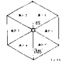
In addition, as mentioned above, in cdma system, the sub-district can be divided into the sector, and a plurality of antennas (antenna diversity) can be used in each sector.Therefore, must define and optimize correctness and softer (promptly being unit) hand-off process of delay spectrum estimation according to the alap hardware specific requirement of complexity with the sector.
Therefore, the multipath transmisstion that invention also has a purpose to provide a kind of DS-SS-CDMA of being used in particular for base station receiver postpones to determine device, when the sub-district is divided into the sector of using antenna diversity, can carries out correct delay spectrum and estimate and More Soft Handoff.
Above purpose can reduce a catalogue of the present invention, promptly provide a kind of multipath transmisstion of the DS-SS-CDMA of being used in particular for base station receiver to postpone to determine device, it can carry out correct despreading in real time simultaneously to speech or the Packet Data Channel that has the frequency pilot sign that periodically inserts in a large number, correct delay spectrum is estimated and correct Path selection and location.
The realization approach of purpose
Above purpose is determined in the device accomplished in a kind of power-delay spectrum that is specifically designed to the cdma base station receiver.This purpose also realizes in the path selection device of a kind of time of delay.This purpose also further is achieved in a kind of search and tracking cell.
Specifically, as main aspect of the present invention, the present invention is by averaging the power-delay spectrum of computed improved to the delay spectrum of estimating on a plurality of continuous slots and frame.Others of the present invention are described in each dependent claims.
A preferred aspect of the present invention is how search delay is composed, to find out and the corresponding local maximum of independent pathway.At this moment, the peak value in the delay spectrum is removed or is changed to 0 of equivalence, to obtain a noise-floor.This noise-floor is averaged, to produce an independent value.Multiply each other with a thresholding coefficient and this noise-floor level then.More original more unmodulated delay spectrum and this product are elected those maximums that wherein are on this product thresholding as useful path.
Another aspect of the present invention is the use of antenna diversity, and promptly two antennas in each sub-district or the sector provide a delay spectrum separately.At this moment, from two delay spectrum additions of each antenna, and only select to be higher than in this delay spectrum sum those peak values of the threshold value after multiplying each other.Compare these two delay spectrums and the thresholding that multiplies each other that detects for the delay spectrum that makes up then separately,, only select also to be higher than in each delay spectrum those paths of thresholding for the individual antenna signal.The delay spectrum that adopts when carrying out Path selection according to produced simultaneously two delay spectrums is relevant estimates, is the delay spectrum that is different from independent each antenna of consideration fully.
According to another aspect of the present invention, each sub-district is divided into several sectors, and each sector provides service by two antennas that use antenna diversity.Although in the prior art, must transmit the information which sector to comprise travelling carriage about to the base station, one aspect of the present invention has used a kind of " the dynamic section search " that combines with the More Soft Handoff of independent pathway selection and high accuracy." position " of mobile station MS determined and can be carried out according to it.
Other preferred embodiment of the present invention and improvement can obtain from each dependent claims.Below, will with reference example invention be described in conjunction with the accompanying drawings.
The accompanying drawing summary
In the accompanying drawings:
Fig. 1 represents according to prior art, the Typical Disposition of CDMA sub-district, mobile station MS and base station BS;
Fig. 2 a represents to use a PN sequence to carry out the principle method of DS-SS CDMA spread spectrum and despreading;
Fig. 2 b represents to use the definition of symbol, bit and chip in the CDMA mode of QPSK;
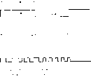
Fig. 3 is illustrated in the channel format that has the frequency pilot sign that periodically inserts on the CDMA transmission channel;
Fig. 4 represents a traditional base station receiver block diagram;
Fig. 5 represents a delay spectrum DPS and multipath transmisstion problem;
Search that Fig. 6 represents that the present invention uses and tracking cell STU block diagram;
Fig. 7 represents according to the present invention, as the selector SEL of search shown in Figure 6 and tracking cell STU parts and a kind of embodiment of searcher S1;
Fig. 8 represents according to the present invention, a kind of embodiment of pilot tone Deplexing apparatus PI-DEMUX shown in Figure 7;
Fig. 9 represents according to the present invention, a kind of embodiment of a kind of embodiment of despreading device DESP and coherent accumulation/equilibration device ACC-AV among the searcher S1 shown in Figure 7;
Figure 10 represents according to the present invention, is used for a kind of embodiment of path selection unit PSU under the situation of selecting the path from two antennas of sector 1;
Figure 11 represents according to the present invention, carries out frequency pilot sign, frame and used time cycle that coherence average uses in coherent accumulation shown in Fig. 7,9/equilibration device ACC-AV;
Figure 12 represents a microzonation is divided into independently sector, and each sector provides service by two antenna Ant1, Ant2;
The schematic diagram of Figure 13 is represented how according to the sector in the searching method News Search of the present invention sub-district;
Figure 14 represents a kind of embodiment of routing resource of the present invention;
Figure 15 represents to search for a kind of embodiment with tracking cell, and it comprises 2 searcher S1, S2, is used to search for 6 sectors that comprise antenna diversity;
Figure 16 represents 3 omission and misinformation probabilities under the sector;
Figure 17 represents 1 omission and misinformation probability under the sector;
Figure 18 represents intersection (cross-over) probability under the 2 footpath Rayleigh fadings; And
Figure 19 is illustrated in the peak noise level at crossover probability place under M=64 and the 2 footpath Rayleigh fading conditions.
Identical or similar part all represented in identical or similar code name in the accompanying drawing in this paper.Below, inventive embodiments will be described with reference to the drawings.
Basic principle of the present invention
As the explanation of having been done with reference to figure 4, RAKE receiver RR is used to handle multipath transmisstion in the DS-CDMA system.RAKE receiver is distributed some parallel demodulators (branch road) by selected strong component in the multipath signal that receives for antenna, thereby should be able to catch most of received signal energy.The output of all branch roads (demodulator) is merged through after the corresponding delay compensation.
The distribution of demodulator (branch road) and time synchronized respond according to estimated channel carries out.The function of multidiameter search processor (searcher hereinafter referred to as) is to estimate the channel power delay spectrum, thus the propagation conditions that path in the identification delay spectrum and tracking change.Therefore, the multidiameter search processor must satisfy the requirement of two mutual contradictions: have enough precise time resolutions when reducing search time, so that reduce the self noise of PN sequence.
Estimate channel impulse response in certain search window according to the definition of spreading code number of phases, the search of this window should be able to cover the maximum delay spread of expectation.The interactive channel impulse response is estimated in being called as certain interval of update time.
Update time must be enough little, changes so that follow the tracks of the delay of wireless channel.The position of channel impulse response in search window with in the motion of travelling carriage and the transmitter and receiver between the PN sequencer mismatch of clock frequency change.Therefore, in order to keep channel impulse response between search window, must adjust the position of whole search window.When multidiameter search processor (searcher) has enough meticulous resolution, with regard to the code tracking equipment that does not need other in every RAKE independent pathway demodulator, to realize usually.
The search of RAKE receiver (see figure 4) and tracking cell STU (seeing appended Fig. 6) are used to keep the chip and the frame synchronization of RAKE receiver.Therefore, the necessary receiving signal delayed spectrum of estimating because of the multipath transmisstion generation.Because decline and propagation distance change, i.e. the influence of variable in distance between mobile station MS and the base station BS need be upgraded this estimation according to the specific requirement of mobile radio channel.
One embodiment of the present of invention have hereinafter been described, can be in certain search window corresponding with postponing expansion with the delay spectrum of good resolution estimating received signal.Delay spectrum is estimated and can for example be repeated in update time at certain at interval.Must select enough for a short time update time, changes so that can follow the tracks of the delay of wireless channel.Therefore, do not need to carry out any special tracking.Be that the position of whole search window must adapt to variable in distance between (tracking) mobile station MS and the base station BS.So search and tracking cell STU can be used for assisting to carry out the sector and select and More Soft Handoff, because the delay spectrum of designated sector can be used for finding to capture maximum signal energy in which sector.
Initial sector selection has arbitrarily been set up in supposition below, initial frame is synchronous and initial chip synchronization (for example at the accidental access signal reception period).But, these conditions are not the principle restriction to this method, and method of the present invention also can be used for this purpose by some adjustment.
Search and tracking cell embodiment
As shown in Figure 6, search of the present invention and tracking cell STU comprise a selector SEL, and its input is two received signal S from antenna Ant1, the Ant2 of each sector 1...6
1, S
2To two signal S of selector SEL input
1, S
2Be because in each sector, preferably adopt the diversity antenna technology that needs to use two antenna Ant1, Ant2.But, be to be understood that the present invention is not limited to antenna diversity in the broader sense, also can use the input as selector SEL from a signal S of each antenna in sector.
Certainly the actual signal that receives from antenna is an analog signal.Be furnished with an A/D converter A/D in the STU device, be used for simulation CDMA conversion of signals is become a digital CDMA signal.Shown in Fig. 3,11, this digital CDMA signal is made up of continuous radio frequency frame RF1...RFn, and every frame comprises the continuous slot TS1...TSm that has inserted multiple frequency pilot sign PSi and data symbol PDi.All common functions are carried out in A/D converter representative, for example analog to digital conversion, matched filtering or the like, and can be arranged in the STU device, for example among the selector SEL, between SEL and fan antenna, perhaps before the searcher S1...SL or within.
In transmitter, the digital transmission signal that comprises a plurality of bits at first for example passes through convolutional encoding with the speed of r=1/3 by bit, bit after 2 convolutional encodings is merged into a QPSK symbol (Q then, I), this symbol passes through the PN sequence spread spectrum of transmitter one side again, and on the other hand, receiver (for example RAKE receiver) and searcher must carry out despreading according to the despreading sequence of correspondence to this symbol equally.This is the direct sequence CDMA basic principle of (promptly comprising the QPSK modulation).It should be noted that and to use other modulation schemes to obtain to carry out the symbol of spread spectrum.Therefore the present invention is not limited to use the QPSK modulation.
Selector SEL is used for extracting the signal sampling group that will search at multidiameter search processor S1...SL (searcher S1...SL hereinafter referred to as).Specifically, each selector SEL extracts frequency pilot sign and some oversamplings (logic channel symbol) from the data flow that receives from each antenna.Frame format and frequency pilot sign are as shown in Figure 3.The best speed with per second 16.38 million of the extraction of frequency pilot sign and oversampling is carried out, and generally is with a kind of oversampling speed, and for example 4.
The search of Fig. 6 and tracking cell STU comprise some searcher S1...SL, and wherein L can be identical or different with number of sectors.
Specifically, according to a kind of specific but sector selection scheduling scheme flexibly, the frequency pilot sign that extracts and other sampling are assigned to the set of L searcher composition.Utilize sector selection scheduling scheme, the number of searcher can equal or be not equal to number of sectors.Six searchers are preferably with same sampling rate work.According to sector selection scheduling scheme, on the basis of signal sampling group, the frequency pilot sign of extraction and oversampling (promptly passing through the aerial signal of demultiplexing and buffering) transmit an independently delay spectrum DPS for each sector signals to path selection unit PSU.
According to the present invention, searcher S1...SL carries out channel latency estimation (determining delay spectrum) according to a kind of (based on frequency pilot sign) is relevant with incoherent combinatorial search (and tracking) program basically, this program has optionally and interweaves, and the searcher S1 according to Fig. 7 below is further described.Delay spectrum DPS preferably upgrades with minimum update time, and preferably uses predetermined frequency pilot sign sampling number.
Path selection unit PSU receives the delay spectrum DPS from searcher S1...SL, and calculates an Interference Estimation (this interference comprises that multi-user interference and thermal noise power disturb) according to the delay spectrum DPS that estimates, is used for follow-up Path selection.According to delay spectrum DPS, in fact path selection unit PSU can determine the median d of N (preferably 8) paths
1' ... d
N' (being length of delay) and corresponding sector selection information s
1' ... s
N'.Information s is selected in the sector
1' ... s
N' represent the antenna number (, can ignore this numbering) in sector number (1...6) and each sector if in each sector, do not use antenna diversity.
Length of delay d
1' ... d
N' only represent the median of N (for example 8) paths, so also will carrying out final sector, tracking and control unit TRCU select, and producing the end value and the selection information (being the selection information of length of delay and correspondence) of (at most) P (for example 8) bar delay path, these information will send RAKE receiver RR at last.Therefore, as shown in Figure 6, the end value d in tracking and control unit TRCU output delay path
1... d
PWith final selection information s
1... s
P, be used for finally should separating the path that mediation is deciphered in RAKE receiver, promptly RAKE receiver should be its path of distributing branch road.In addition, tracking and control unit TRCU also will produce duty controlled clock signal and come track-while-scan window and sub-district, to keep frame synchronization.
Therefore, aerial signal is the input to selector SEL, and selector is giving the last set device from each signal of antenna, and searcher calculates the delay spectrum of each input signal.Then, path selection unit is selected one group of most probable path and the selection information relevant with sector and number of antennas.Final tracking and control unit are determined final path and corresponding selection information, so that provide it to can be used for carrying out the selection information and the deferred message of demodulation to RAKE receiver RR.
Hereinafter will describe the specific embodiment that is used for selector SEL (Fig. 7,8), searcher S1...SL (Fig. 7), path selection unit PSU and tracking and control unit (Figure 10) among the present invention, also be useful on a kind of specific embodiment of despreading device DESP and coherent accumulation and averaging unit ACC-AV according to Fig. 3, frame format shown in Figure 1.
Selector unit embodiment
Fig. 7 represents a selector SEL embodiment.Selector comprises a so-called pilot tone Deplexing apparatus PI-DEMUX.What Fig. 7 represented is the situation that an aerial signal is input to pilot tone Deplexing apparatus PI-DEMUX, but should understand, can be according to the control signal that receives from control device CNTRL, provide different antennae signal continuously to selector SEL from different sectors.
(continuously) frequency pilot sign of a plurality of cycles and additional number sampling are extracted and cushioned to the major function of pilot tone Deplexing apparatus PI-DEMUX from aerial signal, this aerial signal is made up of the input traffic of complex values.Consider the example of Figure 11,, estimate aerial signal radio frequency frame n, and this frame n comprises one group of continuous slot k-1, k, k+1 in order to calculate a delay spectrum DPS (calc.1DPS).
As shown in Figure 3, from a time slot to the conversion of another time slot, for example from time slot k-1 to time slot k, exist a set of pilot symbols PSi who forms by the frequency pilot sign of the frequency pilot sign of last time slot k-1 and current time slots k.The difference of Fig. 3 and Figure 11 is that supposition frequency pilot sign PSi only occurs in the time slot starting point among Fig. 3, and they occur at the starting point and the terminal point of each time slot simultaneously among Figure 11.Because can not guarantee the PN sequence of PN generator generation among time slot and the despreading device DESP all the time aligns in time, therefore as long as can extract some frequency pilot signs that can be used for calculating and data symbol according to PN despreading sequence, whether only at the beginning or end place (the frequency pilot sign present position is the problem of an agreement) frequency pilot sign is sampled and extraction is inessential.Between set of pilot symbols, can be data arbitrarily, for example shown in Figure 3, be the symbol that is used for logic channel etc.
Like this, extracting the frequency pilot sign cycle in fact is exactly to extract frequency pilot sign (shadow region among Figure 11).Preferably extract 2M chip (sampling of 2M * oversampling speed, for example 2 * 128 * 4=1024 sampling) as frequency pilot sign.Preferably from aerial signal (plural input traffic), extract 160 oversamplings (postponing expansion) in addition again.Therefore, the DPS that finally calculates is made up of 160 real number power-delay spectrum sample values.
So, estimate for delay spectrum (search window), use be that resolution is 160 sampling of four sampling of each chip, promptly gained postpones to expand to per second 160/16.38 million sampling ≈ 10 μ s.To suppose also that preferably be 10ms (i.e. radio frequency frame) the minimum update time that is used to recomputate work at present sector (being the strongest predetermined number sector of current demand signal energy) delay spectrum, and scanning inoperative (being other) sector and to select the update time of aerial signal be 60ms (promptly reassigning work and inoperative sector).
Therefore, at least will be in the radio frequency frame of each 10ms, recomputate the time lag of first order spectrum according to the number of frequency pilot sign (1024 sampling) and 160 oversamplings (for example based on 2 time slots time 8 times).Oversampling can be the data of any kind, i.e. control data or voice data.According to the starting point difference of extracting, the order of extraction has difference: perhaps the front is a frequency pilot sign, and the back is a data symbol; Perhaps the front is data symbol (from a last time slot), and the back is a frequency pilot sign, and then is data symbol; Perhaps the front is a data symbol, and the back is a frequency pilot sign.
As shown in Figure 7, response frame clock control signal FCC, the PI-DEMUX of control device CNTRL may command selector SEL makes it to begin to extract frequency pilot sign and diacritic with correct timing in time slot k-1, the k of each frame n, k+ 1.
Fig. 8 represents the embodiment of a kind of pilot tone Deplexing apparatus PI-DEMUX.Controlling sampling switch SSW from the control signal of control device CNTRL, this switch is responsible for delivering to buffer BUF or receiver SNK from the data of aerial signal.Therefore, by means of frame clock control signal FCC, buffer BUF can comprise continuous each frequency pilot sign and oversampling.Any other data are sent to receiver SNK.
Therefore, frame clock signal FCC is controlling location (being read pointer) and the write pointer of sampling switch SSW, i.e. the location of search window in whole delay spectrum, and it is equivalent to inserts in data flow or from wherein removing sampling.
Just as already mentioned, control device CNTRL matches with tracking and control unit TRCU, thereby provide control signal (this signal be used for the work carried out according to specific sector selection scheduling scheme and the selection of inoperative sector) to selector SEL, and control specifically the aerial signal behind demultiplexing distribute searcher S1...SL.This sector selection scheduling program preferably can constitute by (back will explain) shown in Figure 13 mode.
Describe with reference to figure 7,8 as above, the major function of selector SEL is to extract some frequency pilot signs and some oversamplings respectively in each radio frequency frame RFn, and continuously these data values that extract are delivered in the subsequent searches device, with the calculating (wherein will carry out the sector and select and day line options control, make the aerial signal of control Deplexing apparatus PI-DEMUX multiple antenna in each searcher provides from a plurality of sectors continuously) that is used for delay spectrum.Therefore, the subsequent delay spectrum calculating of carrying out in the searcher group is frequency pilot sign and the diacritic to extract.
The number of pilot tone Deplexing apparatus is preferably identical with the possible number of applied aerial signal, for example in Fig. 6,12 pilot tone Deplexing apparatus PI-DEMUX can be arranged.But, this number also can reduce, and when for example using the time that has corresponding Based Intelligent Control to share, can reduce to according to the sector and select the predefined work sector number of control.In fact a minimum pilot tone Deplexing apparatus is just enough.
Multidiameter search processor (searcher) embodiment
As mentioned above, dateout (being the output of buffer BUF among Fig. 8) from selector is continuous plural frequency pilot sign and oversampling (for example 2*128 chip=1024 sampling adds 160 sampling), and these sampling are from certain aerial signal of control device CNTRL appointment.Hereinafter will call " Deplexing apparatus dateout " to data output (being that plural number is led tired symbol and oversampling) from pilot tone Deplexing apparatus PI-DEMUX.As shown in Figure 9, each Deplexing apparatus output data value obviously comprises a real part Rx_Re and an imaginary part Rx_Im.
Shown in Fig. 7 searcher S1 embodiment, searcher comprises a PN code generator PN-GEN who produces the despreading sequence, and this sequence is used at the despreading device DESP that is used for each demodulator dateout despreading.Code generator PN-GEN, despreading device DESP and Deplexing apparatus PI-DEMUX are subjected to the control through the frame clock control signal FCC of control device CNTRL processing.By this control, can guarantee the alignment of PN generator despreading sequence retention time, and be displaced on each the demodulator dateout that extracts, so that computing relay spectrum DPS.As mentioned above, time unifying is necessary, otherwise can produce wrong despreading, because will not only need correct despreading sequence (being produced by code generator PN-GEN) to the correct despreading of demodulator dateout, also needs correct timing.
As shown in Figure 7, be input from the dateout of despreading device DESP to coherent accumulation/equilibration device ACC-AV, this device is computing relay spectrum DPS under the control of control device CNTRL.Delay spectrum is actually response frame clock control signal FCC and produces according to demodulator output signal (frequency pilot sign of extraction and oversampling).According to the present invention, a kind of embodiment of despreading device DESP and coherent accumulation/equilibration device ACC-AV as shown in Figure 9.
Despreading device DESP comprises a relevant apparatus CM who is made of multiplier MM and integrating gear IM.Because the demodulator dateout comprises the despreading sequence that real part and imaginary part and code generator PN-GEN produce and also must comprise real part and imaginary part, so correlator CM is a complex correlator, and multiplier MM then carries out complex multiplication.The starting point of PN sequence is subjected to the control of phase control device PH-CNTRL.
Multiplier MM comprises multiplier M1, M2, M3, M4 and adder ADD1, ADD2.Integrating gear IM comprises addition unit SUM1, SUM2.
Multiplier M1 carries out multiplying each other of Deplexing apparatus dateout real part Rx_Re and frequency expansion sequence real part PN_Re, and the data value after multiplying each other is delivered to adder ADD1.Multiplier M2 carries out multiplying each other of Deplexing apparatus dateout imaginary part Rx_IM and PN sequence real part PN_Re.From the product signal of multiplier M2 is input to adder ADD2.Multiplier M3 carries out multiplying each other of Deplexing apparatus dateout imaginary part Rx_Im and PN sequence imaginary part PN_Im, and the data after multiplying each other are delivered to adder ADD1.Multiplier M4 carries out multiplying each other of Deplexing apparatus dateout real part Rx_Re and PN sequence imaginary part PN_Im, and output signal is delivered to adder ADD2.Adder ADD1 is just to carrying out addition from the output signal of multiplier M1 with from the output signal of multiplier M3, and the signal after the addition delivered to the addition unit SUM1 of integrating gear IM.Adder ADD2 is just to carrying out addition from the output signal of multiplier M2 with from the output signal of multiplier M4, and the signal after the addition delivered to the addition unit SUM2 of integrating gear IM.
Multiplier MM is the result of each pilot chip output from adder ADD1, ADD2, and addition unit SUM1, SUM2 on N pilot chip (for example 2 * 128) carry out addition to the output signal from adder ADD1, ADD2.Because complete data are digital signals, so what carry out the addition correspondence in addition unit SUM1, SUM2 is to the integration from the output signal of multiplier MM.
As a preferred embodiment, PN generator PN-GEN produces the extended code of separating that the short WalshHadamard of complex orthogonal and the conduct of the long Gold of real number (Walsh Hadamard) sign indicating number and demodulator dateout multiply each other.
If drive multiple correlation device CM, have only per the OS time complex multiplication to produce a non zero results with oversampling speed OS.We need consider if the situation when using the QPSK modulation scheme.At this moment, twice real number preferably being divided at a distance of OS/2 of the complex multiplication of carrying out in multiplier MM multiplies each other.Whole code phase is adjusted as increment with the 1/OS of each chip period.Be preferably in the whole time uncertain region (postponing expansion) and use serial search, the constant time of staying that wherein on each code phase location (1/OS of a chip period), has a frequency pilot sign cycle (being 31.25 μ s) here.Therefore, can calculate the code phase of some for each time slot and searcher.Because these processing are that off line is carried out, therefore can handle with higher speed.
The chip sum that computable code phase number equals each time slot with respect to the number of chips of each frequency pilot sign and this cross handle coefficient OP long-pending ratio (here, OP*2560/256=OP*10).An example is the hardware implementations that adopts eight searchers when handling coefficient OP=4 excessively.When being OP=16, adopts the another one example two searchers.
In coherent accumulation/equilibration device ACC-AV, relevant adder unit SUM3 carries out coherent accumulation to the despread values of two continuous pilot symbol periods (promptly with two four frequency pilot signs altogether that time slot is corresponding).Each searcher is the sampling that will calculate 160 delay spectrums altogether in the repetition time of 20/OPms at 2/OP frame (=2*16/OP time slot).This is applicable to that a searcher has the situation of a correlator and a despreading device.By some correlators of combination and despreading device (Fig. 6) in the last set device, can define a kind of parallel search apparatus structure.But, this can't produce restriction to this general description of the present invention.
The plural number output of relevant adder unit SUM3, be real part Re_Imp[phase place] and the Im_Imp[phase place] be sent to squaring cell ABS.In unit ABS, the real part of SUM3 and imaginary part by addition after respectively square (| (a+jb) |
2=a
2+ b
2).The output of unit ABS, be part real number delay spectrum value DPS
iBe the input to adder unit SUM4, this unit carries out noncoherent accumulation to sampling.The output of adder unit SUM4 is actual real number delay spectrum DPS.Therefore, adder unit SUM4 is actually two delay spectrum DPS from two or more time slots in succession
iAverage.So, the basic principle of determining delay spectrum is the channel estimating of carrying out complex values in each time slot, then the complex channel of at least two time slots is estimated that (plural number sampling) do relevant addition, again the delay spectrum (real number value) from (after the addition) channel estimating of two time slots is respectively done incoherent addition at last.
Therefore, the major function of despreading device DESP can be described as the upward PN sequence of alignment and multiplying each other of demodulator dateout of time, and relevant/noncoherent accumulation/equilibration device ACC-AV averages on two or more time slots.This output is (promptly to compose DPS at an average retardation of the frequency pilot sign (+oversampling) of a coherence average in the used cycle based on the demodulator dateout.Therefore, it is much accurate that gained delay spectrum DPS wants, because it has used the frequency pilot sign from continuous slot (or frame).
Following example has illustrated the working condition of despreading device DESP and coherent accumulation/equilibration device ACC-AV.Suppose that each sector adopts antenna diversity, 6 aerial signals of three (work) sectors correspondences in sub-district, they can use 6 searchers to handle in two frames when OP=1.In addition, if only select a sector (work), just can be 3 in 6 searchers of each aerial signal distribution.Correspondingly, the dependency number of each sampling of delay spectrum can improve 3 times.Therefore,, in 2 frames, (see Figure 11) and can calculate 3 continuous delay spectrums, obtain the peak value that reduces and the estimation of interference variance by average energy for OP=1.So just can obtain an improved delay spectrum DPS.
For the situation of OP=16 and 2 searchers, in frame period of 10ms and 16 time slots, can calculate 2*8 (continuously) delay spectrum.Sector controlling mechanism (the sector scheduling will be explained in the back) can promptly be given work and inoperative sector this number assignment.For example, can calculate 3 the continuous delay spectrums of two work sectors (there are two aerial signals each sector) and a delay spectrum (seeing Figure 13) of two inoperative sectors (there are two aerial signals each sector).Therefore, can in each frame, carry out incoherent averaging to the work sector.In 60ms, can also calculate 3 delay spectrums of inoperative sector, therefore also can carry out incoherent averaging the inoperative sector.
For the number of noncoherent accumulation in coherent accumulation/equilibration device (on average) being doubled and don't increasing update time, can use the present invention to be used for average scheme (seeing Figure 11) of a kind of " interweaving " during as 10ms update time.At this moment, to do (further) on average to the delay spectrum and the delay spectrum before update time of latter two continuous (may carry out incoherent averaging) delay spectrum, current calculating gained, so as under 10ms update time constant prerequisite the delay spectrum of computed improved.A kind of preferred interleaving scheme of computing relay spectrum DPS in the following example shown in.In frame n-1, calculate delay spectrum DPS
N-1In present frame n, calculate another delay spectrum DPS then
nTwo delay spectrums are through noncoherent accumulation (addition) in frame n, and addition gained delay spectrum is as the delay spectrum DPS of frame n
n, i.e. DPS
n'=DPS
N-1+ DPS
nThe actual delay spectrum DPS that calculates among the storage frame n
n, add up with next step that is used for next frame n+1.Also can be to the preceding delay spectrum DPS that once calculates
N-1Use a weight coefficient.Can not take just now to two delay spectrum DPS
N-1, DPS
nAdd up (noncoherent accumulation), but also can take the delay spectrum DPS of the some fronts of storage earlier, then these some frames are carried out incoherent addition, to draw the delay spectrum result of frame n.Before adding up, also can be weighted these delay spectrums.Therefore, FIR or IIR filtering characteristic (or weighting) according to each delay spectrum DPS may have different embodiment.
According to another embodiment of coherent accumulation/equilibration device, when using antenna diversity, the delay spectrum of two corresponding fan antennas can addition (in path selection unit PSU) (seeing Fig. 6 and Figure 10).At this moment, coherent accumulation/equilibration device ACC-AV preferably carries out addition to two delay spectrums from two different antennae.
Final delay spectrum DPS according to by adder unit SUM4 output can calculate interference (noise) and estimate in path selection unit PSU.Despreading device DESP and coherent accumulation/equilibration device ACC-AV is controlled by digital signal processor DSP, described relevant and the relevant and noncoherent accumulation processing of this processor control.
No matter which kind of situation can see that despreading device DESP carries out despreading according to frequency pilot sign, and coherent accumulation/equilibration device ACC-AV averages the delay spectrum of calculating according to frequency pilot sign in every frame.Come calculating section delay spectrum DPS according to frequency pilot sign
iBe better than and use random data to determine delay spectrum.Another aspect of the present invention is that the continuous delay spectrum at least two successive frames is averaged, thereby obtains a delay spectrum DPS more accurately.
Path selection unit embodiment
As noted earlier, each independently searcher S1...SL all export a delay spectrum DPS who calculates according to the periodic pilot symbol, the average retardation spectrum that this delay spectrum is preferably calculated according to two successive frames.
To describe path selection unit PSU below and how select the predominating path that comprises among the delay spectrum DPS.A kind of embodiment of path selection unit PSU as shown in figure 10.The functional description of PSU will be since the input of two delay spectrum DPS, and these two delay spectrums are from two antenna Ant1, Ant2 belonging to same sector (being sector 1 among Figure 10).But, should know that each searcher 1...L comprises an equivalent device separately, in order to export main (the strongest) path of each sector respectively.For the present invention is described, supposes here in each sector and use antenna diversity.But the present invention is not limited to antenna diversity.The delay spectrum that Figure 14 is illustrated among the path selection unit PSU is handled.
Path selection unit PSU comprises an adder ADD, peak value detection/delete device PD-RV, path estimation device PEST, noise estimation device NEST, a path testing device PVER1 and PVER2, a maximum checkout gear MAX and a threshold setting device THRS-SET.Noise estimation device NEST receives a thresholding coefficient or a threshold T HRS from threshold setting device THRS-SET.Describe as earlier in respect of figures 6, the major function of this path selection unit PSU is by considering to disturb (noise) to estimate, extract N the path d that signal is the strongest from each delay spectrum DPS1, DPS2
1' ... d
N'.In addition, produce one and selected information s
1' ... s
N', represent selecteed (work) sector (and aerial signal).Delay that calculates according to input delay spectrum and selection information are transmitted to tracking that is used to finally select and control device TRCU as shown in Figure 6.Path selection unit PSU exports the strongest new path and new selection information s in update time (for example 10ms) (i.e. in Zui Xiao each frame period)
1' ... S
N'.
Hereinafter the function of each device of path selection unit PSU will be described with reference to Figure 10 and Figure 14.
If handle two default antenna signals or respective delay spectrum DPS1, the DPS2 of each sector, at first in adder ADD, each delay spectrum DPS1, DPS2 are done addition.Should be pointed out that program described below also is applicable to the situation that does not adopt antenna diversity.At this moment, adder ADD is omitted, and is directly inputed to peak value detection/delete device PD-RV and path estimation device PEST from the gained delay spectrum DPS of each antenna in sector.Therefore, the antenna diversity with two antennas is a preferred embodiment of the present invention.
The total maximum MAX1 (step ST2) of search among the delay spectrum DPS ' after addition (seeing the step ST1 Figure 14).In peak value detection/delete device PD-RV, several sampling of maximum MAX1 and maximum both sides (pulse expansion) (depending on pulse expansion, preferably 3) are deleted or be changed to zero respectively.As previously described,, always have 160 sampling, therefore only delete the whole characteristic that maximum MAX and three sampling about it can't destroy delay spectrum, that is to say in fact and should delete maximum MAX1 for each delay spectrum DPS.Maximum MAX1 and corresponding length of delay d
MAX1Be stored among the peak value detection/delete device PD-RV.
Repeat deletion peaked program (step ST4) from DPS ' N time, thereby obtain N candidate delay value d
Max1, d
Max2... d
MaxnWith the peak value MAX1 of correspondence, the set that MAX2...MAXN forms.Remaining average retardation spectrum
 Be regarded as disturbing (noise), noise estimation device NEST is according to its computation of mean values DPS (step ST4).That is to say that owing to deleted maximum correlation the delay spectrum DPS* after addition, therefore remaining DPS* can be regarded as disturbing or noise.Peaked number preferably should prop up way less than RAKE.
Then, compare stored candidate peak value MAX1, MAX2...MAXN and effective noise level
 With certain self adaptation but constant thresholding coefficient T HRS is long-pending.THRS obtains by a kind of optimizer, and it may reflect the number of the sector number, signal-to-jamming ratio and the noncoherent accumulation that are scanned.Therefore, path estimation device PEST thinks that only being positioned at those values on the effective noise lowest limit is and each direct or indirect corresponding real number length of delay of propagation path independently, and these paths that directapath not necessarily.
If do not use antenna diversity, when promptly only having calculated the delay spectrum (not being the spectrum after the addition) of an antenna, path estimation just comes to an end, that is to say that the selected maximum that is higher than the product thresholding is exactly the input (for each sector) to maximum checkout gear MAX, corresponding all sector N peaked delays of this device output and selection information.
If used antenna diversity, original delay spectrum DPS1, DPS2 that calculates will be through further handling in path testing device PVER1, PVER2 separately.Shown in step ST5, in PVER1, PVER2, (again) at thresholding (promptly alone each other for two delay spectrum DPS1, DPS2
 ) check.In each DPS, have only still greater than those maximums of this thresholding as the candidate peak of each antenna be retained (certainly, if DPS1+DPS2 not by 1/2 normalization, thresholding need adjust by being removed by 2).Therefore, final selected path---by selection information indicated each antenna and sector---has just been determined now.
At this moment, the output of maximum checkout gear MAX is that (by assessing all sectors (for example 6 sectors) according to N maximum of input) maximal correlation postpones d
1' ... d
NTolerance, and representative produces the selection information of the sector of these the strongest maximums and delay thereof.Therefore, the output of maximum checkout gear MAX (actual the output of path selection unit PSU just) is to a tolerance that transmits the propagation path that ceiling capacity (promptly most important) postpones and represents to result from these path delays an indication of (being which sector) where.The maximum checkout gear with maximum by descending from being up to minimum arrangement (comprising the corresponding adjustment of selection information).
Adopt sector system of selection (sector selection scheduling) and adjust relevant treatment according to the following description that will carry out, can work and the inoperative number of sectors between, trade off between the accuracy of update time and gained delay spectrum.That is to say,, can obtain one even more accurate delay spectrum and definite travelling carriage moving between the sector by in each sector, carrying out suitable search (seeing Figure 12) and difference work and inoperative sector.Except can calculating better delay spectrum, the sector is selected also to can be used for More Soft Handoff, that is, generally speaking be exactly to determine more accurately whether location of mobile station and/or definite travelling carriage are on two borders between the sector.
Hereinafter will describe and be used to receive the tracking of above-mentioned path selection unit output and the function of control unit TRCU.
Follow the tracks of and control unit embodiment
As shown in Figure 6, follow the tracks of and control unit TRCU reception from the output of path selection unit PSU (see figure 10), peaked time of delay of the d that promptly correlation that obtains from all path testing device PVER1, PVER2 of all sectors is the strongest
1' ... d
N, and indicate the concrete selection information s that belongs to which sector and which antenna each time of delay
1' ... s
N'.It (is length of delay d that unit TRCU selects now from P the maximum that signal is the strongest in the output of unit PSU (number of P=RAKE branch road)
1... d
P) and corresponding selection information s
1... s
P
But, as long as keep a fixed position (and distance) between mobile station MS and the base station BS, the output of such path selection unit PSU is effective certainly too.If change in location (this is common situation), power-delay spectrum DPS (being time of delay) just may change naturally so.Certainly, each searcher S1...SL can use a predetermined window to decide the power-delay spectrum now.That is to say, the phase place of code generator PN-GEN (and despreading sequence of oversampling) or burst itself can be offset a predetermined number frequency pilot sign by upset of pilot tone Deplexing apparatus or deletion sampling, and this skew is corresponding to counting a predetermined time of delay.Certainly, between mobile station MS and base station BS, set up when communicating by letter for the first time, will even use a predetermined average delay time for directapath P1.In this scheduled time, can determine a predetermined offset distance (postponing expansion) window.But,, must do corresponding skew to the central value that postpones extended window according to the variable in distance between mobile station MS and the base station BS if moving appears in mobile station MS.Here can consider different modes.
Therefore, first function of tracking and control unit TRCU is should (postpone to expand) search window according to the variable in distance adjustment (tracking) between MS and the BS.This operation does not need to carry out continuously, but the minimum update time of 10ms (length of radio frequency frame) enough (OP=16,2 searchers, 2 work sectors, not with 3 incoherent averagings that interweave).By adjusting the read and write pointer in the pilot tone Deplexing apparatus, control the buffer that comprises in the pilot tone Deplexing apparatus of selector SEL thereby insert or delete (frequency pilot sign and data symbol) sampling.By the read and write pointer in the mobile Deplexing apparatus, can realize different starting points and terminal point regularly to the extraction of frequency pilot sign and oversampling, it skew occurs corresponding to the value that causes search window to change.Another kind of possibility is to move aforesaid PN generator phase place.
In switched a sector (softer), two adjacent sectors used a common window offset amount, to keep synchronous.Therefore, this common search window side-play amount also can be used for (adjacent) inoperative sector (at this, can not calculate/estimate the actual power delay spectrum, can detect the sector in path).For a person skilled in the art, by for example considering that the highest maximum MAX1 motion in time makes search window adapt to the motion of travelling carriage or the algorithm of variable in distance (causing postponing to change) is easy to realize.
Except use the search window skew in searcher, tracking and control unit TRCU also have another function also can upgrade the delay path d that has calculated according to the adjustment of search window
1' ... d
N', and the final delay value d of selection some
1... d
PAntenna/sector auxiliary information s with correspondence
1... s
P(P=RAKE number of branches).
Therefore, each PVERn unit transmits one group of " candidate " peak value.Maximum detection unit MAX presses descending to all peak values, and unit TRCU only keeps P maximum (no matter they are from which sector).
All antennas to all working sector are carried out this program, and all " survivors " in all tested aerial signal that will be derived from all working sector according to the sequence descending of maximum power, that have predetermined maximum (promptly prop up way and become, for example P=8) according to RAKE.This sequence represented now the strongest path from all current tested aerial signals, found out (its usually representative be the work sector, but also may comprise current inoperative sector).Selecting new length of delay d according to new descending
1... d
PThe time, also to upgrade selection information certainly, so that show the position of each time of delay, promptly indicate each affiliated sector of each time of delay.This selection information will be told with the search RAKE receiver that output is connected with tracking means STU should remove which signal of demodulation.If the specified path number is less than the maximum path number, RAKE receiver can be received the information (for example by selecting information s to be set to a negative value accordingly) that close some RAKE branch road.
Should be pointed out that the above-mentioned renewal that the time of delay and the selection information of path selection unit PSU output are carried out is not limited to the situation of antenna diversity.If an aerial signal is only used in each sector, just only need to calculate a delay spectrum.
As noted earlier, number of sectors is not necessarily identical with the searcher number.The searcher group preferably is made up of six searchers altogether.But, number of sectors can greater than, be less than or equal to the searcher number.Therefore, the control device CNTRL among Fig. 6 is controlling selector SEL, so that provide different aerial signals (one or two signal of each sector) according to a kind of time sharing mode to each searcher.
The sector selection scheduling
As mentioned above, in the present invention, searcher preferably comes the computing relay spectrum according to the frequency pilot sign that extracts at least two continuous slots in each frame.But, as shown in figure 11, each frame comprises 16 time slots.Suppose selector the entire frame of 10ms on the cycle to one independently searcher (one) is provided aerial signal, searcher obviously can not only be by estimating the calculating that two continuous slots carry out a final delay spectrum so, in fact, searcher can carry out eight calculating (16 time slots) altogether to this aerial signal.But, control device CNTRL can be after the time slot calculating of finishing current aerial signal, another aerial signal of switching on two other time slots (, in fact also having nearly 14 other time slots) because after two time slots of use finish calculating for the first time.To explain hereinafter and carry out the sector scheduling how best that promptly provide aerial signal to the last set device, wherein each searcher calculates at the enterprising line data of continuous two time slots.But should be pointed out that unit TRCU also can use a kind of (non-the best) the sector scanning rule that presets for the predetermined number sector in each sub-district.
At first, tracking and control unit TRCU determine which sector is the work sector, and which sector is the inoperative sector.With d time of delay
1... d
PRelevant selection information s
1... s
PIndicating which current available sector is operating state or non operating state.That is to say, in selection information, indicated in running order sector.
Secondly, tracking and control unit TRCU (or control corresponding device CNTRL) decision can be carried out the how many times coherent accumulation in a frame.As mentioned above, if entire frame comprises 16 time slots, this just represents can carry out altogether in the frame independently coherent accumulation (coherent channel based on 2 time slots is estimated) 8 times.That is to say that the coherent accumulation number of times that can carry out is that timeslot number is divided by 2 in theory in a frame.
Moreover, to follow the tracks of and control unit TRCU determines the noncoherent accumulation number, this is just with the add up different DPS of (their absolute value addition) of incoherent mode
iCalculate the number of (respectively by considering that 2 continuous slots carry out).
In addition, tracking and control unit TRCU are identified for the update time that the power-delay spectrum is upgraded (being window offset).In fact represent to check the cycle of two identical time slots in the same sector that is used to calculate same DPS spectrum update time.The update time that is used for the work sector is not necessarily identical with the inoperative sector.That is to say that because main variation (variable in distance) will occur in the work sector, so do not need to check so continually the inoperative sector, promptly their update time can be more longer.But, in order delay spectrum to be calculated have identical accuracy, the noncoherent accumulation number that carries out in work sector and inoperative sector preferably should be consistent.
At last, in order to determine scheduling scheme, tracking and control unit TRCU and control device CNTRL must know have how many searcher S1...SL to use.That is to say that if the more searcher of multiple parallel work is arranged, nature can scan more sector in a frame.
Therefore, follow the tracks of and control unit TRCU according to desirable desirable update time and the number of sectors (fixing) and the searcher number (fixing equally) in noncoherent accumulation number, work sector and inoperative sector in timeslot number (the coherent accumulation number of times that decision may be carried out), work sector and inoperative sector of work and the number (shown in selection information) of inoperative sector, every frame, determine the sector scanning scheme of any time.
Certainly, sweeping scheme is in case determine, it is only meaningful under the constant condition of sector state (by the indication of selection information) to use this specific sweeping scheme to carry out sector scanning.That is to say,, follow the tracks of so and a kind of different sweeping scheme can be set with control unit if an inoperative sector becomes a work sector (because motion of travelling carriage) suddenly.According to this scheduling scheme, nature can determine travelling carriage to pass the motion that sector borders arrives another sector from a sector by a kind of " soft " mode.That is to say, if travelling carriage is from the direction motion of a work sector to an inoperative sector, the reception antenna of inoperative sector will begin received signal after certain stage of arriving, if travelling carriage is near the border, previous inoperative sector will present one and comprise peaked delay spectrum, and these maximums represent that this sector becomes operating state.But, this judging process is not the hard decision process, because according to sector scanning, in fact can monitor the continuous motion of travelling carriage.
Also might be judged to the work sector in two sectors, other 4 are judged to the inoperative sector.The sector is that the appointment of work or inoperative sector can change, and the number of work and inoperative sector also can change (for example 3 work sector---3 inoperative sectors or the like).
The following table 1 related with Figure 13, Figure 15 represented an example of this sector scheduling scheme.In this example, supposed that whole frame length is 10ms, comprised 16 time slots, therefore had the relevant ability that adds up of to handle 8 times.
For the situation of 1 work inoperative sector, sector/5, allowing the update time of inoperative sector is 50ms, 10ms, 20ms or 30ms.It is 10ms that the work sector requires update time, promptly every frame update.
Under the situation of 2 work inoperative sectors, sector/4, allowing the update time of inoperative sector is 10ms, 20ms or 60ms.
Under the situation of 3 work inoperative sectors, sector/3, be 30ms the update time that requires the inoperative sector.The coherent accumulation number of times that numeral before update time in bracket may be carried out.
In fact, specified in advance in the table 1 and used 2 searchers, its oversampling speed is OP=16, and requiring the update time of each work sector is 10ms.In addition, require the minimum noncoherent accumulation that carries out twice.Its used circuit arrangement as shown in figure 15.Control signal CNTRL will indicate selector when first and second aerial signals of each sector to be delivered to the first and second searcher S1, S2.In Figure 15, suppose first aerial signal always by first searcher S1 processing, second aerial signal is always handled by the second searcher S2.
In table 1, the same number of situation of those noncoherent accumulations and update time separately thereof are represented in the square frame of overstriking.For example, for the situation of 2 work inoperative sectors, sector/4, the inoperative sector only needs per 6 frames (60ms) to upgrade once, and the every frame in sector (10ms) of wherein working upgrades once.But, the noncoherent accumulation number (3) of their uses is identical.Obviously to adding that different restriction (for example improving the update time of inoperative sector) can carry out the more noncoherent accumulation of number update time.
Table 1
| 1 |
5 |
2 |
4 |
3 |
3 inoperative sectors |
| 7(10ms) | 1(50ms) | 2(10ms) | 1(10ms) | 2(10ms) | 2(30ms) |
| 6(10ms) | 2(50ms) | 2(10ms) | 2(20ms) | ||
| 5(10ms) | 3(50ms) | 3(10ms) | 1(20ms) | ||
| 4(10ms) | 4(50ms) | 3(10ms) | 2(40ms) | ||
| 3(10ms) | 1(10ms) | 3(10ms) | 3(60ms) | ||
| 3(10ms) | 2(20ms) | ||||
| 3(10ms) | 3(30ms) |
The example of 2 work inoperative sectors, sector/4 of the update time of above-mentioned 10ms of having and 60ms and three noncoherent accumulations has provided the key message that must how to scan the sector.But, although determined to check the frequency of a sector update time, it does not have concrete invisible scanning sequence.Figure 13 a), b) represented two kinds of different scanning sequences.Among Figure 13, " A " represent a work sector, " A " digitized representation first, second and the 3rd work sector of back, the subscript of digital back represent the number of times of DPS calculating (i.e. the coherent accumulation that carries out) on 2 time slots." N " represent an inoperative sector.
Figure 13 a) in, carry out continuously adding up 1,2,3, i.e. A1 to work three times of sector 1 is relevant
1, A1
2, A1
3, and three DPS of work sector 2 are calculated A2
1, A2
2, A2
34 remaining time slots are used to carry out the DPS calculating first time N1 of inoperative sector in the frame 1
1, N2
1Work as can be seen from frame 2 update time of sector is 10ms, because will use the same DPS sequence of calculation that is used for the work sector every 10ms.But, four remaining time slots can be respectively applied for the scanning to inoperative sector N1, N2, so that carry out DPS calculating second time N1
2, N2
2All keep the scanning to the work sector in each frame, last four time slots in wherein every frame are used to scan the inoperative sector.Because be chosen as 60ms the update time of inoperative sector, the scanning sequence about the inoperative sector in the frame 1 has only to the 7th frame (not shown) and could repeat, and the 7th frame is in fact identical with frame 1.
Figure 13 b) the another kind of implementation of the scheduling scheme of expression his-and-hers watches 1 parameter regulation.Here, the sequence of work sector and inoperative sector scanning is changed, but still satisfy the constraint that table 1 provides.Therefore, level of freedom is still arranged during the scanning in arranging each sector.
According to how carrying out the inoperative sector about its first, second and the relevant for the third time DPS scanning of calculating, finishing for every time after DPS calculates for the third time, can carry out noncoherent accumulation one time, and the variation of estimated delay spectrum.When travelling carriage moves, delay spectrum will change its shape (because different multipath transmisstions), even but delay spectrum changes, and it is operating state that the entire path selected cell will still be indicated this sector.Estimate the delay spectrum of a work sector according to the delay spectrum of one or more adjacent work sector, can make an estimation the travelling carriage direction of motion.Even the inoperative sector still is in non operating state, its delay spectrum does not comprise any maximum (path) that surpasses the appointed threshold level, also can estimate the delay spectrum of inoperative sector with the work sector, because if travelling carriage moves from an inoperative sector to the direction of work sector, even the delay spectrum of inoperative sector also will change.
Therefore, compose with regard to estimated delay when in a single day finishing (in Figure 13 example for 60ms after) by all noncoherent accumulations that in all sectors, carry out, can estimate all delay spectrums together, it can to travelling carriage in the sub-district the position and the direction of motion of travelling carriage make an estimation.
The performance of cdma base station of the present invention
A cdma base station that comprises 6 searchers, OP=1 hereinafter will be discussed.
But the performance characteristic of search and track algorithm is according to delay spectrum supervisory channel path.Channel path becomes to visible in the delay spectrum as the estimation of auto-correlation peak value.Algorithm for estimating must be able to find out these on interference level, auto-correlation peak value with rational signal-to-jamming ratio.The detectability in path depends on the interior signal-to-jamming ratio of RF frequency band and despreading gain and the peak value and the noise variance of searching algorithm.The despreading gain of searching algorithm is defined by the despreading gain of each frequency pilot sign and the coherent accumulation number of de-spread pilot symbols.
For example, for the algorithm that the present invention proposes, this despreading gain for example equals 10*log128*4=27dB.The signal-to-jamming ratio E that channel estimating is seen
Ch/ l
0(i.e. auto-correlation peak value in the delay spectrum of Gu Jiing and the distance between the noise gate) is than the E of each modulation symbol
s/ l
0Height is 10*log512/M (unit is dB) for example, and wherein { 16,32,64,128} is the modulation symbol spread spectrum coefficient to M ∈.Because what use is that speed is 1/3 convolution code and quaternary modulation scheme, E
Ch/ l
0Than corresponding E
b/ l
0Exceed 10*log2*512/3M (unit is dB).Peak value and noise variance reduce along with the increase of incoherent averaging number, and promptly verification and measurement ratio rises, and the misinformation probability that detects a non-existent peak value descends.
Figure 16,17 is illustrated in 2 paths, equal strength, independent rayleigh fading channel, v=50km/h, M=64 and E
b/ l
0Under the situation of=5dB, the probability of the existing peak value of omission and the probability of reverse situation (promptly detect and do not have peak value (" wrong report ")).Basic update time be 20ms (6 searchers, OP=1).Use the antenna diversity and the average scheme that interweaves.This curve is according to peak value-interference threshold, and promptly the ratio of the noise level of (normalized) peak value and correspondence is drawn.Different false dismissal probability curve representation: the detection range (DR) of using 0,1 and 2 sampling.This means that all exceed the peak value that peak value-noise level and its corresponding length of delay be positioned at interval [correct delay-DR correctly postpones+DR] and are all counted as correct detection.' any peak value ' means the delay that counts all peak values that are higher than the peak noise level and do not check its reality.As shown in the figure, the strictness estimation during DR=0 can cause some performance losss.But, for the situation of DR=1, particularly DR=2, not having significantly, the performance loss relevant with false dismissal probability is specified.
Figure 18 represents with E
b/ l
0The algorithm performance that changes.The probable value at point of interface shown in Figure 17 place is extracted.In actual use, should improve the thresholding coefficient slightly, so that provide stronger anti-wrong report ability by introducing a little performance loss.
Figure 19 has described the relation between optimum thresholding coefficient and signal to noise ratio, (being scanned) number of sectors and the noncoherent accumulation number.
Industrial usability
The present invention who is advised is used in any (periodically) and estimates and path detection based on carrying out delay spectrum in the transmission means of frequency pilot sign.Consider the flexibility and the accuracy of restriction, delay spectrum and the Noise Estimation of hardware cost, this is a kind of candidate scheme extremely likely.By adjusting the searcher number, almost can realize any the trading off between accuracy and the hardware cost in conjunction with the proposed way (average mode that OP interweaves) of relevant and noncoherent accumulation.Using incoherent averaging is in order to reduce peak value and noise variance.A variety of sectors selection mode (scheduling scheme) can be adopted.
More than describe and the preferred embodiments of the present invention and example are described as the current optimal mode of the present invention.But, for a person skilled in the art,, obviously can make various changes and distortion to the present invention according to above technical descriptioon.Therefore, not will be understood that the present invention is confined to the foregoing description and example, the scope of the invention is defined by claims.In the claims, code reference number only is used for explanation, does not limit the scope of these claims.
Claims (46)
1. power-delay spectrum is determined device, is used to determine that a plurality of propagation paths (P1, P2) a cdma communication system sub-district (CL) in go up the power-delay that the CDMA signal between cdma base station (BS) and CDMA travelling carriage (MS) transmits and compose (DPS), comprising:
A1) A/D converter (A/D), be used at least one antenna in described sub-district (CL) (Ant1, Ant2) the simulation CDMA multipath signal of Jie Shouing (S1, S2) convert to the digital CDMA multipath signal (S1, S2);
It is characterized in that
A2) described A/D converter (A/D) is used for described simulation CDMA multipath signal (S1, S2) convert digital CDMA multipath signal (S1 to, S2), the latter is made up of continuous radio frequency frame (RF1...RFn), and this radio frequency frame comprises the continuous slot (TS1...TSm) that has multiple frequency pilot sign (PSi) of spread spectrum and spread spectrum data symbol (PDi);
B) Deplexing apparatus (PI-DEMUX), be used at least two continuous slot (TSk-1 from each radio frequency frame (RFn), TSk, TSk+1) the middle spread spectrum that extracts is answered frequency pilot sign (PSi) and spread spectrum data symbol (PDi), and it is stored in the memory (BUF) continuously; And
C) searcher (S1...SL), be used for according to the multiple frequency pilot sign of the described spread spectrum that has extracted and stored and described spread spectrum data symbol (PSi, PDi) determine described each antenna (Ant1, power-delay Ant2) compose (DPS, DPS1, DPS2).
2. the power-delay of claim 1 spectrum is determined device, it is characterized in that
C1) despreading sequencer (PN-GEN) is used to produce a predetermined despreading sequence (DESP-SQ);
C2) despreading device (DESP,
CM, MM IM), is used for according to described despreading sequence (DESP-SQ; PN_Re is PN_Im) to the multiple frequency pilot sign (PSi of each described spread spectrum; Rx_Re Rx_Im) carries out despreading, so that export each time slot (TSk_1, TSk, the multiple pilot value of despreading TSk+1) (PSi ', Rx_Re ', Rx_Im ');
C3) be used for equilibration device (ACC_AV) that the multiple pilot value of described despreading (PSi ', Rx_Re ', Rx_Im ') is averaged, comprise:
C31) coherent accumulation device (SUM3), be used at least two continuous slots (TSk-1, TSk, TSk+1) real part of the multiple pilot value of Dui Ying despreading (PSi ') and imaginary part (PSi ', Rx_Re ', Rx_Im ') a complex power delay spectrum of coherent phase addition sample value (
 , Re_Imp (phase place), Im_Imp (phase place));
C32) absolute value is determined device (ABS), by determine a described complex power delay spectrum sample value (
 Re_Imp (phase place), Im_Imp (phase place)) absolute value is exported a real number power-delay spectrum sample value; And
C33) control device (PN-CNTRL), be used for described despreading sequence and the multiple frequency pilot sign (PSi) of spread spectrum of described extraction and storage and the continuous skew that the phase place between the described spread spectrum data symbol (PDi) is made pre-determined number to described despreading sequencer (PN-GEN) generation, wherein said absolute value is determined the real number power-delay spectrum sample value (DPSi) of device (SQ) according to phase deviation output predetermined number, as a real number power-delay spectrum (DPS).
3. the power-delay of claim 2 spectrum is determined device, it is characterized in that
Described despreading device (DESP,
CMMM, IM), described coherent accumulation device (SUM3) and described absolute value determine that device (ABS) determines one group of real number power-delay spectrum sample value (DPSi) in each phase deviation place, each value adds as the basis with the coherent phase of the multiple frequency pilot sign of corresponding despreading at least two continuous slots, and at least two continuous slots that one of them value is used are different from those time slots that another value is used;
Noncoherent accumulation device (SUM4) is used for corresponding real number power-delay spectrum sample value is done incoherent addition, so that export a real number power-delay spectrum sample value (DPS).
4. the power-delay of claim 2 spectrum is determined device, it is characterized in that
Path selection unit (PSU) is used for determining described multipath transmission predetermined number propagation path (P1, (d time of delay P2) according to described real number power-delay spectrum (DPS)
1' ... d
N').
5. the power-delay of claim 4 spectrum is determined device, it is characterized in that
Follow the tracks of and control unit (TRCU), be used for being adjusted at the search window that searcher (S1...SL) uses, and according to the position between described travelling carriage (MS) and described base station (BS) and/or variable in distance upgrade power-delay compose (DPS) and time of delay (d
1' ... d
N').
6. the power-delay of claim 1 spectrum is determined device, it is characterized in that
Described Deplexing apparatus (PI-DEMUX) comprises a switch (SSW), described storage device (BUF) and a receiver (SNK), wherein control device (CNTRL) is controlled described switch (SSW) according to a frame clock control signal (FFC), so that transmit the multiple frequency pilot sign and the data symbol of described extraction continuously to described storage device (BUF), and transmit other data symbols of described time slot to described receiver (SNK).
7. the power-delay of claim 2 spectrum is determined device, it is characterized in that
Described despreading device (DESP) comprises a complex correlator (CM) of being made up of multiplier (MM) and integrating gear (IM).
8. the power-delay of claim 7 spectrum is determined device, it is characterized in that
Described multiplier (MM) comprises first, second, third and fourth multiplier (the M1, M2, M3, M4) and the first and second adder (ADD1, ADD2), wherein first multiplier (M1) multiplies each other to real part (PN_Re) work of a symbol in the real part (Rx_Re) of the multiple frequency pilot sign of each spread spectrum and the described despreading sequence, described second multiplier (M2) multiplies each other to real part (PN_Re) work of a symbol in the imaginary part (Rx_Im) of the multiple frequency pilot sign of described spread spectrum and the described despreading sequence, described the 3rd multiplier (M3) multiplies each other to imaginary part (PN_Im) work of symbol described in the imaginary part (Rx_Im) of the multiple frequency pilot sign of each spread spectrum and the described despreading sequence, described the 4th multiplier (M4) multiplies each other to imaginary part (PN_Im) work of symbol described in the real part (Rx_Re) of the multiple frequency pilot sign of each spread spectrum and the described despreading sequence, described first adder (ADD1) is to from the first and the 3rd multiplier (M1, M3) addition is done in output, described second adder (ADD2) is to from described second and described the 4th multiplier (M2, M4) addition is done in output, wherein said integrating gear (IM) comprises the first and second adder unit (SUM1, SUM2), they in the pilot chip (N pilot chip) of predetermined number respectively to from the described first and second adder (ADD1, ADD2) output valve is carried out addition, the wherein said first and second adder unit (SUM1, SUM2) export respectively the real part of the multiple pilot value of described despreading and imaginary part (PSi ', Rx_Re ', Rx_Im ').
9. the power-delay of claim 4 spectrum is determined device, it is characterized in that described path selection unit (PSU) comprising:
Peak value detection/delete device (PD-RV), be used for detecting the peak value (MAX1 of predetermined number in described power-delay spectrum (DPS), MAX2, MAXn), and at least the oversampling of those corresponding with the institute detection peak in the described real number power-delay spectrum (DPS) sampling and described maximum left and right sides predetermined number is changed to zero or deletion;
Noise estimation device (NEST), be used for to peak value sampling and described oversampling be changed to zero or the real number power-delay spectrum (DPS) of deletion average, to determine an effective noise value; And
Path estimation device (PEST), be used for selecting to exceed a thresholding (
 * THRS) (d time of delay that is determined peak value
1' ... d
N'; d
Max1, d
Max2, d
MaxN), this thresholding multiplies each other by an effective noise value and a thresholding coefficient (THRS) and produces.
* THRS) (d time of delay that is determined peak value
1' ... d
N'; d
Max1, d
Max2, d
MaxN), this thresholding multiplies each other by an effective noise value and a thresholding coefficient (THRS) and produces.
10. the power-delay of claim 9 spectrum is determined device, it is characterized in that described path selection unit (PSU) is suitable for determining the time of delay of the last CDMA signal that transmits of described a plurality of propagation paths (P1, P2) in described CDMA sub-district (CL) between described cdma base station (BS) and described CDMA travelling carriage (MS), this sub-district is divided into a predetermined number sector (SECT1...SECT6), each sector has two diversity reception antenna (Ant1, Ant2), the time of delay that be associated with one of described sector described time of delay, and comprise:
Adder (ADD), be used for two diversity reception antenna (Ant1 each sector, Ant2) first and second real number power-delay spectrum (DPS1, DPS2) be added to an additional power-delay spectrum (DPS '), wherein detection peak and it is changed to zero in the real number power-delay spectrum of peak value detections/delete device (PD-RV) after described addition (DPS ');
Described noise estimation device (NEST) is averaged to described additional power-delay spectrum; With
(PVER1 PVER2), is respectively applied at determined length of delay (d the first and second path testing devices
Max1, d
Max2, d
MaxN) go up relatively by the definite product thresholding of described path estimation device (PEST) (
 * THRS) (DPS1 DPS2), wherein has only the peak value that is equal to or greater than this product thresholding in the first and second real number power-delay spectrum just to be detected with the described first and second real number power-delay spectrum of each antenna.
11. the power-delay of claim 10 spectrum is determined device, it is characterized in that
Maximum checkout gear (MAX), be used for receiving each path testing device (PVER1 from a plurality of searchers (S1...SL), PVER2) candidate peak, each searcher is one or more sectors (SECT1...SECT6) services, this maximum checkout gear (MAX) also will to by the path testing device of each searcher (S1...SL) (PVER1, PVER2) peak-peak of Shu Chu predetermined number (N) and time of delay (d
1' ... d
N') carry out descending, and determine each of (d time of delay
1' ... d
N') selection information (s
1' ... s
N'), this information is indicated each of (d time of delay
1' ... d
N') belong to which sector (SECT1...SECT6).
12. the power-delay of claim 1 spectrum is determined device, it is characterized in that
Described searcher (S1...SL) can be used in to each comprises the radio frequency frame (RFn) of 16 time slots determines a plurality of real number power-delay spectrums (DPS) incoherently.
13. the power-delay of claim 11 spectrum is determined device, it is characterized in that
Described tracking and control unit (TRCU) can be used in and receive described selection information (s
1' ... s
N') and described time of delay (d
1' ... d
N'), and can select (d time of delay of predetermined number (P)
1... d
P) and corresponding selection information (s
1... s
P).
14. the power-delay of claim 13 spectrum is determined device, it is characterized in that
For by described selection information (s
1' ... s
N'; s
1... s
P) indication work at present and inoperative sector, described tracking and control unit (TRCU) can be used in and use a kind of predetermined sector scanning rule, so that commander's choice device (SEL) according to described sector scanning rule to a plurality of searchers (S1...SL) provide each aerial signal from each sector (SECT1...SECT6) (Ant1, Ant2).
15. the power-delay of claim 14 spectrum is determined device, it is characterized in that
Described tracking and control unit (TRCU) can be used in the scheduled update cycle (10ms) of time slot (TSi) number according to each radio frequency frame (RFn), total sector (SECT1...SECT6) number, searcher (S1...SL) number, work sector and by described selection information (s
1' ... s
N'; s
1... s
P) indication work at present and inoperative number of sectors, real number power-delay spectrum (DPS) be concerned with and the pre-determined number of incoherent calculating and the update cycle (SECT1...SECT6) of inoperative sector, determine to indicate each time slot (TSi) of each radio frequency frame (RFn) should scan the described sector scanning rule of which sector.
16. the power-delay of claim 14 spectrum is determined device, it is characterized in that
Described tracking and control unit (TRCU) can be used in estimates each real number power-delay spectrum (DPS) variation each other in time in each work and the inoperative sector, to determine the cell sector (CL) and the direction of motion at described travelling carriage (MS) place.
17. the power-delay of claim 14 spectrum is determined device, it is characterized in that
In case a sector state that is scanned is when work becomes inoperative or inverse change, described tracking and control unit (TRCU) can be used in selects a kind of new sector scanning rule.
18. a cdma base station, it comprises according to the definite device in claim 1 or 2.
19. the cdma base station of claim 18 is characterized in that
Follow the tracks of and control unit (TRCU), be used for being adjusted at the search window that described searcher (S1...SL) uses, and according to the position between described travelling carriage (MS) and described base station (BS) and/or variable in distance upgrade power-delay compose (DPS) and time of delay (d
1' ... d
N').
20. the cdma base station of claim 19 is characterized in that
Described CDMA sub-district (CL) by described cdma base station (BS) service is divided into a predetermined number sector (SECT1...SECT6), each sector comprises at least one antenna (Ant1, Ant2), described A/D converting means (A/D) all described aerial signals convert to a correspondence the digital CDMA multipath signal (S1, S2);
The searcher (S1...SL) of predetermined number is provided; And
A choice device (SEL) also is provided, it according to an application controls sequence of control device (CNTRL) output come to each searcher (S1...SL) provide described digital CDMA multipath signal (S1, S2).
21. the cdma base station of claim 20 is characterized in that
Each sector (SECT1...SECT6) comprises two antenna (Ant1, Ant2), described choice device (SEL) offers a searcher (S1...SL) to the CDMA of the changed digital multipath signal (S1...S2) from each sector (SECT1...SECT6) respectively.
22. the cdma base station of claim 20 or 21 is characterized in that
The number of sector (SECT1...SECT6) equals the number of searcher (S1...SL).
23. the cdma base station of claim 20 or 21 is characterized in that
The number of sector (SECT1...SECT6) less than or the number of great-than search device (S1...SL).
24. the cdma base station of claim 21 is characterized in that a path selection unit (PSU) comprising:
Adder (ADD), be used for two antenna (Ant1 each sector, Ant2) first and second real number power-delay spectrum (DPS1, DPS2) be added to an additional real number power-delay spectrum, wherein detection peak and it is changed to zero in the real number power-delay spectrum of peak value detections/delete device (PD-RV) after described addition (DPS ');
(PVER1 PVER2), is respectively applied at determined length of delay (d the first and second path testing devices
Max1, d
Max2, d
MaxN) go up relatively by the definite product thresholding of path estimation device (PEST)
 (DPS1 DPS2), wherein has only the peak value that is equal to or greater than this product thresholding in the first and second real number power-delay spectrum just to be detected with the described first and second real number power-delay spectrum of each antenna.
25. the cdma base station of claim 24 is characterized in that
Maximum checkout gear (MAX), be used for receiving each path testing device (PVER1 from a plurality of searchers (S1...SL), PVER2) candidate peak, each searcher is one or more sectors (SECT1...SECT6) services, this maximum checkout gear (MAX) also will to by the path testing device of each searcher (S1...SL) (PVER1, PVER2) peak-peak of Shu Chu predetermined number (N) and time of delay (d
1' ... d
N') carry out descending, and determine each of (d time of delay
1' ... d
N') selection information (s
1' ... s
N'), this information is indicated each of (d time of delay
1' ... d
N') belong to which sector (SECT1...SECT6).
26. the cdma base station of claim 25 is characterized in that
Described tracking and control unit (TRCU) can be used in and receive the described selection value of information (s
1' ... s
N') and described time of delay (d
1' ... d
N'), and can select (d time of delay of predetermined number (P)
1... d
P) and corresponding selection information (s
1... s
P).
27. the cdma base station of claim 26 is characterized in that
For by described selection information (s
1' ... s
N'; s
1... s
P) indication work at present and inoperative sector, described tracking and control unit (TRCU) can be used in and use a kind of predetermined sector scanning rule, so that command described choice device (SEL) according to described sector scanning rule to a plurality of searchers (S1...SL) provide each aerial signal from each sector (SECT1...SECT6) (Ant1, Ant2).
28. the cdma base station of claim 27 is characterized in that
Described tracking and control unit (TRCU) can be used in the scheduled update cycle (10ms) of time slot (TSi) number according to each radio frequency frame (RFn), total sector (SECT1...SECT6) number, searcher (S1...SL) number, work sector and by described selection information (s
1' ... s
N'; s
1... s
P) indication work at present and inoperative number of sectors, real number power-delay spectrum (DPS) be concerned with and the pre-determined number of incoherent calculating and the update cycle (SECT1...SECT6) of inoperative sector, determine to indicate each time slot (TSi) of each radio frequency frame (RFn) should scan the described sector scanning rule of which sector.
29. the cdma base station of claim 27 or 28 is characterized in that
Described tracking and control unit (TRCU) can be used in estimates each real number power-delay spectrum (DPS) variation each other in time in each work and the inoperative sector, to determine the cell sector (CL) and the direction of motion at described travelling carriage (MS) place.
30. the cdma base station of claim 27 or 28 is characterized in that
In case a sector state that is scanned is when work becomes inoperative or inverse change, described tracking and control unit (TRCU) can be used in selects a kind of new sector scanning rule.
31. the cdma base station of claim 18 is characterized in that
Described power-delay spectrum determines that device (STU) links to each other with the RAKE receiver (RR) of described cdma base station (BS) or described travelling carriage (MS).
32. a CDMA travelling carriage, it comprises according to the definite device in claim 1 or 2.
33. the CDMA travelling carriage of claim 32 is characterized in that
Follow the tracks of and control unit (TRCU), be used for adjusting the search window that uses at searcher (S1...SL) at least, and according to the position between described travelling carriage (MS) and described base station (BS) and/or variable in distance upgrade power-delay compose (DPS) and time of delay (d
1' ... d
N').
34. the CDMA travelling carriage of claim 32 is characterized in that
Described CDMA sub-district (CL) by described cdma base station (BS) service is divided into a predetermined number sector (SECT1...SECT6), each sector comprises at least one antenna (Ant1, Ant2), described A/D converting means (A/D) all described aerial signals convert to a correspondence the digital CDMA multipath signal (S1, S2);
The searcher (S1...SL) of predetermined number is provided; And
A choice device (SEL) also is provided, it according to an application controls sequence of control device (CNTRL) output come to each searcher (S1...SL) provide described digital CDMA multipath signal (S1, S2).
35. the CDMA travelling carriage of claim 34 is characterized in that
Each sector (SECT1...SECT6) comprises two antenna (Ant1, Ant2), described choice device (SEL) offers a searcher (S1...SL) to the CDMA of the changed digital multipath signal (S1...S2) from each sector (SECT1...SECT6) respectively.
36. the CDMA travelling carriage of claim 34 or 35 is characterized in that
The number of sector (SECT1...SECT6) equals the number of searcher (S1...SL).
37. the CDMA travelling carriage of claim 34 or 35 is characterized in that
The number of sector (SECT1...SECT6) less than or the number of great-than search device (S1...SL).
38. the CDMA travelling carriage of claim 35 is characterized in that described path selection unit (PSU) comprising:
Adder (ADD), be used for two antenna (Ant1 each sector, Ant2) first and second real number power-delay spectrum (DPS1, DPS2) be added to an additional real number power-delay spectrum, wherein peak value detects in the real number power-delay spectrum of delete device (PD-RV) after described addition (DPS ') detection peak and it is changed to zero;
(PVER1 PVER2), is respectively applied at determined length of delay (d the first and second path testing devices
Max1, d
Max2, d
MaxN) go up relatively by the definite product thresholding of path estimation device (PEST)
 (DPS1 DPS2), wherein has only the peak value that is equal to or greater than this product thresholding in the first and second real number power-delay spectrum just to be detected with the described first and second real number power-delay spectrum of each antenna.
39. the CDMA travelling carriage of claim 38 is characterized in that
Maximum checkout gear (MAX), be used for receiving each path testing device (PVER1 from a plurality of searchers (S1...SL), PVER2) candidate peak, each searcher is one or more sectors (SECT1...SECT6) services, this maximum checkout gear (MAX) also will be to path testing device (PVER1, PVER2) peak-peak of Shu Chu predetermined number (N) and the length of delay (d thereof by each searcher (S1...SL)
1' ... d
N') carry out descending, and determine each of (d time of delay
1' ... d
N') selection information (s
1' ... s
N'), this information is indicated each of (d time of delay
1' ... d
N') belong to which sector (SECT1...SECT6).
40. the CDMA travelling carriage of claim 39 is characterized in that
Described tracking and control unit (TRCU) can be used in and receive the described selection value of information (s
1' ... s
N') and described time of delay (d
1' ... d
N'), and can select (d time of delay of predetermined number (P)
1... d
P) and corresponding selection information (s
1... s
P).
41. the CDMA travelling carriage of claim 40 is characterized in that
For by described selection information (s
1' ... s
N'; s
1... s
P) indication work at present and inoperative sector, described tracking and control unit (TRCU) can be used in and use a kind of predetermined sector scanning rule, so that command described choice device (SEL) according to described sector scanning rule to a plurality of searchers (S1...SL) provide each aerial signal from each sector (SECT1...SECT6) (Ant1, Ant2).
42. the CDMA travelling carriage of claim 41 is characterized in that
Described tracking and control unit (TRCU) can be used in the scheduled update cycle (10ms) of time slot (TSi) number according to each radio frequency frame (RFn), total sector (SECT1...SECT6) number, searcher (S1...SL) number, work sector and by described selection information (s
1' ... s
N'; s
1... s
P) indication work at present and inoperative number of sectors, real number power-delay spectrum (DPS) be concerned with and the pre-determined number of incoherent calculating and the update cycle (SECT1...SECT6) of inoperative sector, determine to indicate each time slot (TSi) of each radio frequency frame (RFn) should scan the described sector scanning rule of which sector.
43. the CDMA travelling carriage of claim 41 or 42 is characterized in that
Described tracking and control unit (TRCU) can be used in estimates each real number power-delay spectrum (DPS) variation each other in time in each work and the inoperative sector, to determine the cell sector (CL) and the direction of motion at described travelling carriage (MS) place.
44. the CDMA travelling carriage of claim 41 or 42 is characterized in that
In case a sector state that is scanned is when work becomes inoperative or inverse change, described tracking and control unit (TRCU) can be used in selects a kind of new sector scanning rule.
45. the CDMA travelling carriage of claim 32 is characterized in that
Described power-delay spectrum determines that device (STU) links to each other with the RAKE receiver (RR) of described cdma base station (BS) or described travelling carriage (MS).
46. the cdma base station of claim 20 comprises search and tracking cell (STU), is used for basis to (d time of delay
Max1... d
MaxN) a plurality of propagation paths (P1, P2) in a CDMA sub-district (CL) of determining to decide go up the position and/or the direction of motion of the CDMA travelling carriage (MS) of transmission of CDMA signal between described cdma base station (BS) and CDMA travelling carriage (MS), this sub-district is divided into predetermined number destination sector (SECT1...SECT6), each sector has two reception antenna (Ant1, Ant2), comprising:
The searcher of described predetermined number (S1...SL) be used for determining each sector multipath transmission described real number power-delay spectrum (DPS1, DPS2);
Path selection unit (PSU), be used for according to described real number power-delay spectrum (DPS1, DPS2) determine described multipath transmit in the strongest propagation path (P1, (d time of delay P2) of predetermined number
1' ... d
N') and indicate described time of delay of (d
1' ... d
N') belong to which work the sector (SECT1...SECT6) corresponding selection information (s
1' ... s
N');
Described tracking and control unit (TRCU) are suitable for the described selection information (s according to described time of delay and indication work and inoperative sector
1' ... s
N') determine a kind of predetermined sector scanning rule, so that commander's choice device (SEL) provides specific aerial signal according to concrete timing to described searcher (S1...SL) in each time slot (TSi) of radio frequency frame (RFn), and estimate the real number power-delay spectrum (DPS) that when specific aerial signal is provided to searcher (S1...SL), obtains respectively, so that determine the position and/or the direction of motion of travelling carriage (MS) in the CDMA sub-district.
Applications Claiming Priority (2)
| Application Number | Priority Date | Filing Date | Title |
|---|---|---|---|
| DE19824218.2 | 1998-05-29 | ||
| DE19824218A DE19824218C1 (en) | 1998-05-29 | 1998-05-29 | Multipath propagation delay determining device using periodically inserted pilot symbols |
Publications (2)
| Publication Number | Publication Date |
|---|---|
| CN1311924A CN1311924A (en) | 2001-09-05 |
| CN100385812C true CN100385812C (en) | 2008-04-30 |
Family
ID=7869404
Family Applications (1)
| Application Number | Title | Priority Date | Filing Date |
|---|---|---|---|
| CNB998092304A Expired - Fee Related CN100385812C (en) | 1998-05-29 | 1999-05-17 | Multipath propagation delay determination means using periodically inserted pilot symbols |
Country Status (9)
| Country | Link |
|---|---|
| EP (2) | EP1082821B1 (en) |
| JP (1) | JP4480889B2 (en) |
| KR (1) | KR100694927B1 (en) |
| CN (1) | CN100385812C (en) |
| AR (1) | AR019597A1 (en) |
| AU (1) | AU756608B2 (en) |
| CA (1) | CA2333479C (en) |
| DE (1) | DE19824218C1 (en) |
| WO (1) | WO1999063677A1 (en) |
Families Citing this family (40)
| Publication number | Priority date | Publication date | Assignee | Title |
|---|---|---|---|---|
| JP3412689B2 (en) | 1999-08-26 | 2003-06-03 | 日本電気株式会社 | Mobile phone |
| US7428265B1 (en) | 1999-11-12 | 2008-09-23 | Cornell Research Foundation | Systems and methods for optimal symbol spacing to minimize intersymbol interference in a receiver |
| TW486914B (en) * | 1999-12-02 | 2002-05-11 | Ericsson Telefon Ab L M | Synchronization of diversity handover destination base station |
| JP2001196975A (en) * | 2000-01-17 | 2001-07-19 | Nec Corp | Synchronization acquisition circuit for cdma wireless base station |
| JP3943305B2 (en) * | 2000-01-19 | 2007-07-11 | 三菱電機株式会社 | Spread spectrum receiving apparatus and spread spectrum receiving method |
| JP3566895B2 (en) * | 2000-02-15 | 2004-09-15 | 株式会社エヌ・ティ・ティ・ドコモ | Leading wave position detecting device, receiving device, leading position detecting device, leading wave position detecting method, and leading position detecting method |
| DE10012875B4 (en) | 2000-03-16 | 2004-04-01 | Infineon Technologies Ag | pager |
| JP4255601B2 (en) * | 2000-06-14 | 2009-04-15 | 株式会社エヌ・ティ・ティ・ドコモ | Method for establishing synchronization of mobile stations in a mobile communication system |
| JP2002026768A (en) * | 2000-07-07 | 2002-01-25 | Nec Corp | Communication unit |
| JP2002164812A (en) | 2000-11-24 | 2002-06-07 | Nec Corp | Path search circuit for spread spectrum communication |
| JP3428637B2 (en) * | 2000-11-27 | 2003-07-22 | 日本電気株式会社 | Multipath detection method and circuit for CDMA receiver |
| US6980803B2 (en) | 2000-12-04 | 2005-12-27 | Telefonaktiebolaget Lm Ericsson (Publ) | Using statistically ascertained position for starting synchronization searcher during diversity handover |
| US6907245B2 (en) | 2000-12-04 | 2005-06-14 | Telefonaktiebolaget Lm Ericsson (Publ) | Dynamic offset threshold for diversity handover in telecommunications system |
| US6954644B2 (en) | 2000-12-04 | 2005-10-11 | Telefonaktiebolaget Lm Ericsson (Publ) | Using geographical coordinates to determine mobile station time position for synchronization during diversity handover |
| JP2004289191A (en) * | 2001-01-19 | 2004-10-14 | Yozan Inc | Path search method and receiver in ds-cdma system |
| EP1386411B1 (en) * | 2001-05-08 | 2005-07-20 | Siemens Aktiengesellschaft | Method for detecting multipath signals |
| TWI261468B (en) | 2001-11-02 | 2006-09-01 | Benq Corp | Rake reception device and method |
| JP4089245B2 (en) * | 2002-03-06 | 2008-05-28 | 日本電気株式会社 | Mobile communication terminal device, cell search control method thereof, and program |
| KR100485516B1 (en) | 2002-04-22 | 2005-04-27 | 주식회사 케이티프리텔 | Basestation and method for receiving and processing signal in the basestation |
| FR2841407B1 (en) * | 2002-06-20 | 2004-08-13 | Nec Technologies Uk Ltd | METHOD FOR OPTIMIZING CELL SEARCH IN A MOBILE TELECOMMUNICATION NETWORK |
| DE10238300B4 (en) * | 2002-08-21 | 2006-08-10 | Infineon Technologies Ag | Method and architecture for transferring symbols of a rake-finger structure to task-specific hardware modules |
| US7142586B2 (en) | 2002-09-18 | 2006-11-28 | Telefonaktiebolaget Lm Ericsson (Publ) | Robust delay estimation architecture |
| JP4165238B2 (en) * | 2003-01-29 | 2008-10-15 | 日本電気株式会社 | Path search circuit, method and program |
| DE10303912B4 (en) * | 2003-01-31 | 2005-03-17 | Infineon Technologies Ag | Method and apparatus for determining energy delay profiles in a data stream transmission over multiple data transmission paths |
| EP1453218A1 (en) * | 2003-02-28 | 2004-09-01 | Siemens Aktiengesellschaft | Method for the evalutation of signals in a receiving station of a radio system and receiving station |
| US20050113142A1 (en) * | 2003-11-20 | 2005-05-26 | Telefonaktiebolaget Lm Ericsson (Publ) | Temporal joint searcher and channel estimators |
| US20050111598A1 (en) * | 2003-11-20 | 2005-05-26 | Telefonaktiebolaget Lm Ericsson (Publ) | Spatio-temporal joint searcher and channel estimators |
| US7308286B2 (en) | 2003-11-20 | 2007-12-11 | Telefonaktiebolaget Lm Ericsson (Publ) | Multi-dimensional joint searcher and channel estimators |
| CN1622501B (en) * | 2003-11-25 | 2011-06-08 | 华为技术有限公司 | A method and apparatus for extracting multi-path |
| US7421271B2 (en) | 2004-04-12 | 2008-09-02 | Lucent Technologies Inc. | Sector switching detection method |
| JP4448403B2 (en) * | 2004-08-16 | 2010-04-07 | 富士通株式会社 | Power level measuring apparatus and mobile station |
| US7372895B2 (en) | 2004-12-08 | 2008-05-13 | Telefonaktiebolaget Lm Ericsson (Publ) | Method of and system for delay estimation with minimized finger allocation |
| US7480356B2 (en) | 2004-12-08 | 2009-01-20 | Telefonaktiebolaget L M Ericsson (Publ) | Method of and system for path selection in rich multipath conditions |
| US7826800B2 (en) | 2006-11-27 | 2010-11-02 | Orthosoft Inc. | Method and system for determining a time delay between transmission and reception of an RF signal in a noisy RF environment using phase detection |
| US20080151969A1 (en) * | 2006-12-21 | 2008-06-26 | Andres Reial | Efficient Delay Profile Computation with Receive Diversity |
| CN101425819B (en) * | 2007-10-31 | 2013-03-20 | 凌阳电通科技股份有限公司 | Method and apparatus for time sequence control in channel estimation |
| JP5125916B2 (en) * | 2008-09-10 | 2013-01-23 | 富士通株式会社 | Reception device and communication control method |
| CN102045815B (en) * | 2009-10-10 | 2013-01-30 | 中国科学院计算技术研究所 | Cell searching device and method used for LTE (Long Term Evolution) system |
| JP5891623B2 (en) * | 2011-07-07 | 2016-03-23 | ソニー株式会社 | COMMUNICATION CONTROL DEVICE, COMMUNICATION CONTROL METHOD, AND PROGRAM |
| CN108777591B (en) * | 2018-05-31 | 2020-06-02 | 清华大学 | Digital gain controller and control method |
Citations (4)
| Publication number | Priority date | Publication date | Assignee | Title |
|---|---|---|---|---|
| WO1996010873A1 (en) * | 1994-09-30 | 1996-04-11 | Qualcomm Incorporated | Multipath search processor for a spread spectrum multiple access communication system |
| EP0738049A1 (en) * | 1995-04-14 | 1996-10-16 | Agence Spatiale Europeenne | Spread spectrum signal receiver using an autoadaptive detection threshold |
| EP0776105A1 (en) * | 1995-06-13 | 1997-05-28 | Ntt Mobile Communications Network Inc. | Cdma demodulator |
| CN1166727A (en) * | 1996-03-18 | 1997-12-03 | 摩托罗拉公司 | Method for determining weighting coefficients in CDMA radio receiver |
Family Cites Families (3)
| Publication number | Priority date | Publication date | Assignee | Title |
|---|---|---|---|---|
| US5490165A (en) * | 1993-10-28 | 1996-02-06 | Qualcomm Incorporated | Demodulation element assignment in a system capable of receiving multiple signals |
| US5648983A (en) * | 1995-04-24 | 1997-07-15 | Lucent Technologies Inc. | CDMA rake receiver with sub-chip resolution |
| US5945948A (en) * | 1996-09-03 | 1999-08-31 | Motorola, Inc. | Method and apparatus for location finding in a communication system |
-
1998
- 1998-05-29 DE DE19824218A patent/DE19824218C1/en not_active Expired - Fee Related
-
1999
- 1999-05-17 WO PCT/EP1999/003386 patent/WO1999063677A1/en active IP Right Grant
- 1999-05-17 JP JP2000552784A patent/JP4480889B2/en not_active Expired - Lifetime
- 1999-05-17 CA CA002333479A patent/CA2333479C/en not_active Expired - Fee Related
- 1999-05-17 AU AU42631/99A patent/AU756608B2/en not_active Ceased
- 1999-05-17 KR KR1020007013465A patent/KR100694927B1/en not_active IP Right Cessation
- 1999-05-17 EP EP99955374A patent/EP1082821B1/en not_active Expired - Lifetime
- 1999-05-17 CN CNB998092304A patent/CN100385812C/en not_active Expired - Fee Related
- 1999-05-17 EP EP03000023A patent/EP1303058B1/en not_active Expired - Lifetime
- 1999-05-28 AR ARP990102551A patent/AR019597A1/en active IP Right Grant
Patent Citations (4)
| Publication number | Priority date | Publication date | Assignee | Title |
|---|---|---|---|---|
| WO1996010873A1 (en) * | 1994-09-30 | 1996-04-11 | Qualcomm Incorporated | Multipath search processor for a spread spectrum multiple access communication system |
| EP0738049A1 (en) * | 1995-04-14 | 1996-10-16 | Agence Spatiale Europeenne | Spread spectrum signal receiver using an autoadaptive detection threshold |
| EP0776105A1 (en) * | 1995-06-13 | 1997-05-28 | Ntt Mobile Communications Network Inc. | Cdma demodulator |
| CN1166727A (en) * | 1996-03-18 | 1997-12-03 | 摩托罗拉公司 | Method for determining weighting coefficients in CDMA radio receiver |
Also Published As
| Publication number | Publication date |
|---|---|
| JP4480889B2 (en) | 2010-06-16 |
| AU4263199A (en) | 1999-12-20 |
| CA2333479A1 (en) | 1999-12-09 |
| EP1082821A1 (en) | 2001-03-14 |
| WO1999063677A1 (en) | 1999-12-09 |
| AU756608B2 (en) | 2003-01-16 |
| EP1303058A3 (en) | 2005-02-02 |
| KR100694927B1 (en) | 2007-03-14 |
| CA2333479C (en) | 2008-12-16 |
| CN1311924A (en) | 2001-09-05 |
| KR20010052444A (en) | 2001-06-25 |
| AR019597A1 (en) | 2002-02-27 |
| EP1303058B1 (en) | 2007-07-11 |
| JP2002517938A (en) | 2002-06-18 |
| DE19824218C1 (en) | 2000-03-23 |
| EP1303058A2 (en) | 2003-04-16 |
| EP1082821B1 (en) | 2003-04-16 |
Similar Documents
| Publication | Publication Date | Title |
|---|---|---|
| CN100385812C (en) | Multipath propagation delay determination means using periodically inserted pilot symbols | |
| US6731622B1 (en) | Multipath propagation delay determining means using periodically inserted pilot symbols | |
| CN100413228C (en) | Communications in an asynchronous wireless network | |
| AU760919B2 (en) | Cdma receiving method and circuit | |
| KR100347655B1 (en) | Demodulation element assignment in a system capable of receiving multiple signals | |
| JP3425372B2 (en) | Communication signal receiving method | |
| US6373882B1 (en) | Motion estimator for a CDMA mobile station | |
| JP3159378B2 (en) | Spread spectrum communication system | |
| KR20010014261A (en) | Mobile station synchronization within a spread spectrum communications system | |
| US6377615B1 (en) | Apparatus and methods for receiving information using variable length accumulation searchers | |
| KR20010051111A (en) | Reception apparatus and reception processing method | |
| US6377614B1 (en) | Spreading code synchronization circuit and method | |
| US5903596A (en) | Spread spectrum demodulation unit | |
| CA2221919C (en) | Spread spectrum receiver for use in communication systems | |
| EP0964529A2 (en) | Channel estimation apparatus and communication terminal apparatus | |
| KR20000047620A (en) | Communication terminal apparatus and radio communication method | |
| WO2002063794A1 (en) | System and method for multistage interference cancellation | |
| KR100504360B1 (en) | Receiver and reception method | |
| KR20040054127A (en) | A signal detecting device and a operating method thereof multipath searcher for receiving modem on base station | |
| GB2351879A (en) | RAKE receiver for CDMA cellular system | |
| EP1715594B1 (en) | Selecting delay values for a RAKE receiver | |
| EP1672808B1 (en) | Selecting peak delay values for a RAKE receiver | |
| RU2332800C2 (en) | Method of search in multiple access communication with code division |
Legal Events
| Date | Code | Title | Description |
|---|---|---|---|
| C06 | Publication | ||
| PB01 | Publication | ||
| C10 | Entry into substantive examination | ||
| SE01 | Entry into force of request for substantive examination | ||
| C14 | Grant of patent or utility model | ||
| GR01 | Patent grant | ||
| CF01 | Termination of patent right due to non-payment of annual fee | ||
| CF01 | Termination of patent right due to non-payment of annual fee |
Granted publication date: 20080430 Termination date: 20170517 |