CN100384670C - Adaptive calibration of X-Y position sensor - Google Patents
Adaptive calibration of X-Y position sensor Download PDFInfo
- Publication number
- CN100384670C CN100384670C CNB018182089A CN01818208A CN100384670C CN 100384670 C CN100384670 C CN 100384670C CN B018182089 A CNB018182089 A CN B018182089A CN 01818208 A CN01818208 A CN 01818208A CN 100384670 C CN100384670 C CN 100384670C
- Authority
- CN
- China
- Prior art keywords
- mentioned
- torque
- clutch
- engine
- claw clutch
- Prior art date
- Legal status (The legal status is an assumption and is not a legal conclusion. Google has not performed a legal analysis and makes no representation as to the accuracy of the status listed.)
- Expired - Fee Related
Links
Images


Classifications
-
- B—PERFORMING OPERATIONS; TRANSPORTING
- B60—VEHICLES IN GENERAL
- B60W—CONJOINT CONTROL OF VEHICLE SUB-UNITS OF DIFFERENT TYPE OR DIFFERENT FUNCTION; CONTROL SYSTEMS SPECIALLY ADAPTED FOR HYBRID VEHICLES; ROAD VEHICLE DRIVE CONTROL SYSTEMS FOR PURPOSES NOT RELATED TO THE CONTROL OF A PARTICULAR SUB-UNIT
- B60W10/00—Conjoint control of vehicle sub-units of different type or different function
- B60W10/04—Conjoint control of vehicle sub-units of different type or different function including control of propulsion units
- B60W10/06—Conjoint control of vehicle sub-units of different type or different function including control of propulsion units including control of combustion engines
-
- F—MECHANICAL ENGINEERING; LIGHTING; HEATING; WEAPONS; BLASTING
- F16—ENGINEERING ELEMENTS AND UNITS; GENERAL MEASURES FOR PRODUCING AND MAINTAINING EFFECTIVE FUNCTIONING OF MACHINES OR INSTALLATIONS; THERMAL INSULATION IN GENERAL
- F16H—GEARING
- F16H61/00—Control functions within control units of change-speed- or reversing-gearings for conveying rotary motion ; Control of exclusively fluid gearing, friction gearing, gearings with endless flexible members or other particular types of gearing
-
- B—PERFORMING OPERATIONS; TRANSPORTING
- B60—VEHICLES IN GENERAL
- B60W—CONJOINT CONTROL OF VEHICLE SUB-UNITS OF DIFFERENT TYPE OR DIFFERENT FUNCTION; CONTROL SYSTEMS SPECIALLY ADAPTED FOR HYBRID VEHICLES; ROAD VEHICLE DRIVE CONTROL SYSTEMS FOR PURPOSES NOT RELATED TO THE CONTROL OF A PARTICULAR SUB-UNIT
- B60W10/00—Conjoint control of vehicle sub-units of different type or different function
- B60W10/10—Conjoint control of vehicle sub-units of different type or different function including control of change-speed gearings
- B60W10/11—Stepped gearings
-
- B—PERFORMING OPERATIONS; TRANSPORTING
- B60—VEHICLES IN GENERAL
- B60W—CONJOINT CONTROL OF VEHICLE SUB-UNITS OF DIFFERENT TYPE OR DIFFERENT FUNCTION; CONTROL SYSTEMS SPECIALLY ADAPTED FOR HYBRID VEHICLES; ROAD VEHICLE DRIVE CONTROL SYSTEMS FOR PURPOSES NOT RELATED TO THE CONTROL OF A PARTICULAR SUB-UNIT
- B60W30/00—Purposes of road vehicle drive control systems not related to the control of a particular sub-unit, e.g. of systems using conjoint control of vehicle sub-units, or advanced driver assistance systems for ensuring comfort, stability and safety or drive control systems for propelling or retarding the vehicle
- B60W30/18—Propelling the vehicle
- B60W30/19—Improvement of gear change, e.g. by synchronisation or smoothing gear shift
-
- F—MECHANICAL ENGINEERING; LIGHTING; HEATING; WEAPONS; BLASTING
- F16—ENGINEERING ELEMENTS AND UNITS; GENERAL MEASURES FOR PRODUCING AND MAINTAINING EFFECTIVE FUNCTIONING OF MACHINES OR INSTALLATIONS; THERMAL INSULATION IN GENERAL
- F16H—GEARING
- F16H63/00—Control outputs from the control unit to change-speed- or reversing-gearings for conveying rotary motion or to other devices than the final output mechanism
- F16H63/40—Control outputs from the control unit to change-speed- or reversing-gearings for conveying rotary motion or to other devices than the final output mechanism comprising signals other than signals for actuating the final output mechanisms
- F16H63/50—Signals to an engine or motor
- F16H63/502—Signals to an engine or motor for smoothing gear shifts
-
- B—PERFORMING OPERATIONS; TRANSPORTING
- B60—VEHICLES IN GENERAL
- B60W—CONJOINT CONTROL OF VEHICLE SUB-UNITS OF DIFFERENT TYPE OR DIFFERENT FUNCTION; CONTROL SYSTEMS SPECIALLY ADAPTED FOR HYBRID VEHICLES; ROAD VEHICLE DRIVE CONTROL SYSTEMS FOR PURPOSES NOT RELATED TO THE CONTROL OF A PARTICULAR SUB-UNIT
- B60W2510/00—Input parameters relating to a particular sub-units
- B60W2510/10—Change speed gearings
- B60W2510/1005—Transmission ratio engaged
-
- B—PERFORMING OPERATIONS; TRANSPORTING
- B60—VEHICLES IN GENERAL
- B60W—CONJOINT CONTROL OF VEHICLE SUB-UNITS OF DIFFERENT TYPE OR DIFFERENT FUNCTION; CONTROL SYSTEMS SPECIALLY ADAPTED FOR HYBRID VEHICLES; ROAD VEHICLE DRIVE CONTROL SYSTEMS FOR PURPOSES NOT RELATED TO THE CONTROL OF A PARTICULAR SUB-UNIT
- B60W2510/00—Input parameters relating to a particular sub-units
- B60W2510/10—Change speed gearings
- B60W2510/1015—Input shaft speed, e.g. turbine speed
-
- B—PERFORMING OPERATIONS; TRANSPORTING
- B60—VEHICLES IN GENERAL
- B60W—CONJOINT CONTROL OF VEHICLE SUB-UNITS OF DIFFERENT TYPE OR DIFFERENT FUNCTION; CONTROL SYSTEMS SPECIALLY ADAPTED FOR HYBRID VEHICLES; ROAD VEHICLE DRIVE CONTROL SYSTEMS FOR PURPOSES NOT RELATED TO THE CONTROL OF A PARTICULAR SUB-UNIT
- B60W2510/00—Input parameters relating to a particular sub-units
- B60W2510/10—Change speed gearings
- B60W2510/104—Output speed
-
- B—PERFORMING OPERATIONS; TRANSPORTING
- B60—VEHICLES IN GENERAL
- B60W—CONJOINT CONTROL OF VEHICLE SUB-UNITS OF DIFFERENT TYPE OR DIFFERENT FUNCTION; CONTROL SYSTEMS SPECIALLY ADAPTED FOR HYBRID VEHICLES; ROAD VEHICLE DRIVE CONTROL SYSTEMS FOR PURPOSES NOT RELATED TO THE CONTROL OF A PARTICULAR SUB-UNIT
- B60W2540/00—Input parameters relating to occupants
- B60W2540/16—Ratio selector position
- B60W2540/165—Rate of change
-
- B—PERFORMING OPERATIONS; TRANSPORTING
- B60—VEHICLES IN GENERAL
- B60W—CONJOINT CONTROL OF VEHICLE SUB-UNITS OF DIFFERENT TYPE OR DIFFERENT FUNCTION; CONTROL SYSTEMS SPECIALLY ADAPTED FOR HYBRID VEHICLES; ROAD VEHICLE DRIVE CONTROL SYSTEMS FOR PURPOSES NOT RELATED TO THE CONTROL OF A PARTICULAR SUB-UNIT
- B60W2710/00—Output or target parameters relating to a particular sub-units
- B60W2710/06—Combustion engines, Gas turbines
- B60W2710/0666—Engine torque
-
- F—MECHANICAL ENGINEERING; LIGHTING; HEATING; WEAPONS; BLASTING
- F16—ENGINEERING ELEMENTS AND UNITS; GENERAL MEASURES FOR PRODUCING AND MAINTAINING EFFECTIVE FUNCTIONING OF MACHINES OR INSTALLATIONS; THERMAL INSULATION IN GENERAL
- F16H—GEARING
- F16H2306/00—Shifting
- F16H2306/40—Shifting activities
- F16H2306/44—Removing torque from current gears
-
- F—MECHANICAL ENGINEERING; LIGHTING; HEATING; WEAPONS; BLASTING
- F16—ENGINEERING ELEMENTS AND UNITS; GENERAL MEASURES FOR PRODUCING AND MAINTAINING EFFECTIVE FUNCTIONING OF MACHINES OR INSTALLATIONS; THERMAL INSULATION IN GENERAL
- F16H—GEARING
- F16H2306/00—Shifting
- F16H2306/40—Shifting activities
- F16H2306/46—Uncoupling of current gear
Abstract
A method/system for adaptively controlling engine fueling during disengagement of a jaw clutch (70) while maintaining the vehicle master friction clutch (20) engaged. Engine torque is initially commanded to a zero drive line torque value (114) and, after a period of time (T2-T1) if non-torque lock is not sensed ((d/dt(SLY-Y))<REF), than a torque bump (128) engine fueling routine is initiated.
Description
Background of invention
Related application
The application is involved in the adaptive calibration of submitting on June 25th, 2000 that is entitled as the X-Y position transduser, and transfers the U.S. Patent application of sequence number No.09/587503 of the application's cessionary Eaton.
Invention field
The present invention relates to a kind of position transduser of a kind of use, for example a kind of sensor that is used for detecting the Y-Y position of vehicle gearbox selector shift component, judge the method/system of the state (pattern) of engine fuel supply, need not the vehicle master clutch so that can shift into neutral gear and throw off.More specifically, the present invention relates to a kind of adaptive technique, this technology is utilized the gear-shift lever that one of a detected shift component-for example can move by a kind of " H type " gear figure or gear shift refers to or autoshift actuator-the rate of change of Y-Y position, to judge whether needing one to force the torque reverse program to change to neutral gear.
The invention still further relates to and a kind ofly be used to make motor torque to equal a computing value so that the method/system of a transmission system no-load torque (zero torque) to be provided, wherein, motor torque is with a rate variation as the function of the speed ratio of detected throttle control position and/or joint.
Background technology
In H type gear figure, be used for the hand gear shifting lever of mobile shift component and X-Y gearshift for example gear shift refer to etc. at prior art it is well-known, can be referring to U.S. Patent No. 5481170, No.5281902, No.4899607, No.4821590, No.4784007, No.4455883 and No.4515029, disclosing of these patents is hereby expressly incorporated by reference.
In H type gear figure, the position transduser of discontinuous position type that is used for detecting discontinuous (dispersing) X-Y position of shift component is known at prior art, can be referring to U.S. Patent No. 4817468 and 4718307.The X-X of analog or digital signal and its numerical value representative shift component in H type gear figure and/or the sensor of Y-Y position and/or axle power (shaft force) are provided, be known in prior art, can be referring to U.S. Patent No. 5911787, No.5743143, No.5481170 and No.5950491, disclosing of these patents is hereby expressly incorporated by reference.Be used for detecting other shift component for example the sensor of the position of piston, ball-screw etc. also be known at prior art.
Judge to wish when the speed ratio of a current joint shifts into neutral gear and shifts into a goals ratio then, when keeping the vehicle main friction clutch to engage, start automatic fuel control, so that all or part of automatic mechanical transmission systems that the torque on claw clutch to be broken away from reduces, also be known in prior art, can be referring to U.S. Patent No. 4850236, No.5582558, No.5735771, No.5775639 and No.6015366, disclosing of these patents is hereby expressly incorporated by reference.
These systems comprise attempts supply engine fuel to reach the system of transmission system no-load torque, referring to U.S. Patent No. 4593580, disclosing of this patent is hereby expressly incorporated by reference, with supply engine fuel to force to carry out one or the reverse system of torque repeatedly, referring to U.S. Patent No. 4850236.
Utilize and force the reverse system that especially repeats to force the reverse engine fuel supply technology of torque of torque, provide a kind of height failure-free program to be used to allow to change to neutral gear, but may the desirable shift feel of how many out of reachs.Utilize target to be and attempt to remain on the system of the engine fuel supply technology of transmission system no-load torque, a kind of gear shift fuel (shift fuel) of better quality is provided, but does not have the reliability that the claw clutch of desirable feasible joint breaks away from acceptably.
Summary of the invention
According to the present invention, a kind of adaptive engine fuel feeding control is provided, it is based on a kind of detected motion, be preferably a shift component for example at the movement rate of gear-shift lever of Y-Y direction etc., to use engine fuel supply to be the transmission system no-load torque, (b) or on claw clutch to be broken away from, produce torque shock ends (torque bump) to force torque reverse to reach optimal (a) target; Or (c) their combination.
In a preferred embodiment, above-mentioned control is following realization: when judgement need shift into transmission neutral, make driving engine be supplied to fuel, in monitoring shift component position, to make a determined output (flywheel) torque cause one to be the transmission system no-load torque substantially.After after a while, if the rate of change of this shift component position is greater than an a reference value, then desirablely basic reach (as showing towards the ability that the Y-Y Neutral Position moves gear-shift lever) for the no-load torque condition, and one is N/R to the reverse torque shock ends program of pressure torque by the operator.Yet if the movement rate of this shift component is not to equal this a reference value at least, this torque shock ends program may be also will being activated of needing.
Therefore, one object of the present invention is to provide a kind of method/system of improvement, is used for controlling adaptively engine fuel supply, need not main friction clutch to neutral gear and keeps breaking away to allow to change.The control of this adaptive engine fuel be a detected shift component position-for example in a kind of H type gear figure movably the Y-Y position of shift component-variation or the function of rate of change.
Become clear after the explanation of the preferred embodiment that this purpose of the present invention and other purpose and advantage will be associated with accompanying drawing below reading.
Brief description
Fig. 1 is a kind of scheme drawing that uses the vehicle transmission system of adaptive engine fuel feeding of the present invention control method/system;
Figure 1A is a kind of and a kind of scheme drawing of claw clutch assembly commonly used of mechanical transmission use;
Fig. 2 is the scheme drawing of an X-Y position transduser using in a preferred embodiment of adaptive engine fuel feeding of the present invention control method/system;
Fig. 3 is the scheme drawing of a kind of autoshift actuator of being used for using in another embodiment of the present invention;
Fig. 4 is the diagrammatic representation of engine fuel control of the present invention;
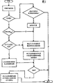
Fig. 5 is the scheme drawing of adaptive engine fuel of the present invention control method/system of representing with the diagram of circuit form;
The scheme drawing of the further embodiment of adaptive engine fuel feeding of the present invention control method/system that Fig. 6 A and Fig. 6 B represent with the diagram of circuit form;
Preferred embodiment describes in detail
In Fig. 1, schematically show a kind of use adaptive engine fuel feeding control technology of the present invention to the automatic vehicle powertrain systems 10 of small part.This system 10 can be full automatic, shown in the example in the U.S. Patent No. 4361060, can be that part is automatic, shown in the example among U.S. Patent No. 4648290 and the No.5409432, or have the auxiliary manually operated of controller, shown in the example among U.S. Patent No. 4850236, No.5582558, No.5735771 and the No.6015336.
In system 10, one comprises and a part-time case (demultiplicator, splitter) the auxiliary gear box part 16 of type be connected in series manually or the pick-off gear change-speed box 12 of autoshift main gearbox part 14, by main friction clutch 20 or other non-rigid adapter manual or operation automatically, can be connected with a for example well-known spark ignition engine of combustion engine 18 or diesel engine drivingly.Preferably, this auxiliary gear box part 16 is one three layers four fast compound type part-time case/gear bands (range) types, and as shown in U.S. Patent No. 4754665 and No.5390561, disclosing of these patents is hereby expressly incorporated by reference.
Gear Figure 12 A shown in Fig. 2 is a kind of well-known " H type ", comprise the two or more (R and the 1/ 2nd of vertical branch (leg) along the stretching, extension of so-called " Y-Y " (or joint/disengaging) direction, the 3/ 4th and the 5/ 6th, the 7/ 8th and the 9/ 10th grade), the level that stretches and be positioned at the center Neutral Position of Y-Y direction with an edge " X-X " (or select) direction is connected the 12B of branch.
Gear figure will be called gear figure at this employed term " H type ", one of them shift component, for example a gear shift refers to SF etc., (I) selectively move in the X-X direction, with with two or more branch of stretching along the Y-Y direction in selected one aim at, (II) can leave or move in the Y-Y direction towards a center Neutral Position, engaging with selected gear ratio respectively or to break away from, and (III) only when Neutral Position in the Y-Y direction can with position that selected branch aims between move along the X-X direction.
Controller auxiliary gear box system 10 also comprises the tachogen 32 that is used for detection of engine rotating speed (ES), be used to detect the tachogen 34 of input shaft rotating speed (IS), with the tachogen 36 that is used to detect output shaft rotating speed (OS), and provide its indicator signal.A sensor 37 provides a kind of signal THL that indicates the throttle control position.This signal is generally a percentum (0% to 100%) of fuel Throttle Position.Driving engine 18 can be used electron steering, comprises one according to a kind of industry-standard protocol SAE J-1922 for example, SAE J-1939, operation such as ISO11898 pass through the electronic controller 38 that a kind of electronic data link (DL) is communicated by letter.A kind of manually-operated pedal of clutch (not shown) or a kind of automatic actuater (not shown) can be used to optionally engage or break away from (often connecing) master clutch 20 of common joint, and this is well-known in prior art.
Be provided with a slave part actuator 40, in order to the gear shift and/or the gear ratios of control slave part part-time case.Preferably, at least this part-time case actuator is one three position actuator, allow this part-time case part by gear shift to and remain on a high part-time case speed ratio, a low part-time case speed ratio or a part-time case Neutral Position, the more detailed content of its structure and advantage can be referring to U.S. Patent No. 5651292, No.5974906 and No.5970810, and disclosing of this patent is hereby expressly incorporated by reference.
Sensor element 46A and 46B can provide some signals like this, and they change with the position of being detected at the value such as aspects such as frequency, amplitude, voltage, electric current, pressure.U.S. Patent No. 5743143 and European patent No.0371975 show displacement sensing apparatus commonly used.
Although X-X and Y-Y motion is shown as general vertical axial motion, a kind of axially and a kind of rotatablely moving (as shown in U.S. Patent No. 5743143 and 5911787) also be considered as being included in X-X and the Y-Y motion.
Fig. 3 shows a kind of alternate embodiments, and wherein, a gear shifting actuator 100 moves according to the instruction of ECU52, so that range fork 102 moves along the Y-Y direction, is used for engaging selectively and breaking away from the claw clutch (not shown).A kind of sensor 104 provides the signal SF of the position of detected range fork of indication and related shift component
Y-Y
Figure 1A shows a kind of representative type claw clutch assembly 70, is used for selectively a gear 72 engaged going up or be separated from an axle 74, and a transmission main shaft for example is in order to engage or to break away from a converter speed ratio.In brief, clutch components 76 usefulness splined are used for its axial motion and therewith rotation relatively to axle 74.Clutch components 76 has outer clutch teeth 78, is used for and is formed on internal clutch teeth 80 joints in the interior diameter hole of gear 72.Clutch components 76 is by an axial location such as control fork (not shown).This control fork is usually by similar device axial location on a control fork rail, sliding selector shaft, ball slideway or ball-screw, piston or the function.
As is known, with a vehicle mechanical formula change-speed box particularly the claw clutch in the heavy-duty vehicle break away from, need to remove the torque locking of the claw clutch that engages.If to open master clutch 20 be irrealizable or be not desirable, the torque locking can be by the transmission system no-load torque of supply engine fuel to cause supposing, and/or reverse releasing of pressure torque of the intersection (crossings) by can causing the transmission system no-load torque on one's own initiative.Though the control engine fuel supply will cause a higher-quality gear shift in the hope of realizing and remaining on transmission system no-load torque value, may not can the in fact feasible underload disengagement of claw clutch that engages of this method.Using one " torque shock ends " or other program is the height failure-free to realize passing the pressure torque of waiting to break away from claw clutch reverse, but may cause a more inferior-quality gear shift.
The control motor torque is to realize desirable output or flywheel torque and can be known in and referring to U.S. Patent No. 5620392, disclosing of this patent is hereby expressly incorporated by reference.
This employed motor torque refer to indication motor torque-be generally a driving engine total torque-value, can calculate or estimate output or flywheel torque from this value.The pass of driving engine total torque and flywheel torque ties up among U.S. Patent No. 5509867 and the No.5490063 and discusses, and disclosing of these patents is hereby expressly incorporated by reference.
One or more engine torque value can be from a kind of industrial standard data link, i.e. DL, and the data link that for example meets SAE J-1922, SAE J-1939 or ISO 11898 is assigned instruction or is read.
According to the present invention, need shift into neutral gear from the speed ratio of a joint and when not throwing off master clutch 20 detecting, this driving engine is at first run to an engine torque value of judging or calculating based on detected system operating parameters by order, with corresponding to the transmission system no-load torque.
With reference to Fig. 4, if gear shift starts at a transmission condition 110, this motor torque will be dropped to the computing value 114 that is assumed to corresponding to transmission system no-load torque condition along curve 112 by order.Similarly, if start in a skid conditions 116 to the gear shift of neutral gear, this motor torque will be risen to this computing value 114 along curve 118 by order.Preferably, curve 112 and 116 slope (gradient) (being the rate of change of motor torque) are the speed ratio of just being thrown off and/or the function of current Throttle Position THL.In the transmission system no-load torque condition 120 that reaches supposition (in time T
1) time, driving engine will be remained on 122 a period of time of this condition (T by order
2-T
1).This section period (T
2-T
1) be typically about the 150-300 microsecond.The time 124 that stops in this section period, detected shift component for example gear-shift lever 42 or gear shift refers to that the speed of SF compares with an a reference value REF.If the speed of shift component equals or exceeds this a reference value ((d/dt (SL
Y-Y))>REF), it is mobile that this shows that this shift component is breaking away from towards claw clutch with a speed, shows that no torque locking condition and torque shock ends program are unnecessary or are not desirable.Under this condition, this driving engine will be continued to produce the output torque of a supposition corresponding to transmission system no-load torque (solid line 126) by order, up to detecting transmission neutral.
If this detected shift component speed is not equal to or is no more than this a reference value ((d/dt (SL
Y-Y))<REF), then the torque locking may exist, and the torque shock ends fuel feeding program (dotted line 128) at the pressure torque reverse (130) of claw clutch of driving engine will begin, stop up to detecting neutral gear and/or a time period.The numerical value and/or the shape of this torque shock ends 128 change in time.
Fig. 5 is the scheme drawing of an adaptive engine fuel feeding control subprogram of the present invention of representing with the diagram of circuit form.Preferably, this subprogram will be carried out during each Control Circulation.
When the speed of utilizing shift component as example judges whether that target is controlled the purpose that is reaching its releasing torque locking for the fuel of no-load torque, whether other parameter for example power on an actuator, electric current, loss in voltage, pressure or the like also can be monitored, be instructed in the existing of torque locking condition at claw clutch place to be thrown off to judge.
If do not have position or other shift component monitoring sensor, a failure that realizes neutral gear can be used as the indication that may there be and needs torque shock ends in torque locking condition.
Fig. 6 A and 6B are the scheme drawings of the further embodiment of an adaptive engine fuel feeding of the present invention control method/system that represents with the diagram of circuit form.
In a preferred embodiment of the invention, throttle gate rate of curve high and/or low greater than throttle gate or during with a lower speed ratio (for example the 1st, the 2nd or the 3rd speed in one 10 speed transmission) with the rate of curve (rate of change of motor torque) of a higher speed ratio (for example the 8th, the 9th or the 10th speed in one 10 speed transmission) when engaging.
The invention is intended to be applicable to the hand shift of a main gearbox part and/or the actuator gear shift of master and/or auxiliary gear box part.
Therefore, provide new and an improve system/method as can be seen, be used for controlling engine fuel supply adaptively in claw clutch and the main friction clutch disengagement that engages.
Although the present invention particular case by to a certain degree is illustrated; but the explanation that is appreciated that the preferred embodiment is just as example, and under the situation of the spirit and scope of the present invention for required protection the multiple modification and the specific embodiment can be arranged below not breaking away from.
Claims (10)
1. method that is used at vehicle automatic speed variator system control engine fuel supply, this automatic transmission with hydraulic torque converter system comprises a combustion engine (18) that drives the input shaft (18) of a multiple gear ratios change-speed box (12) by a main friction clutch (20), above-mentioned change-speed box has at least two speed ratios by rigidity claw type clutch engagement and disengaging, and this claw clutch has the claw clutch parts (76) that can be moved to a selected position in a joint and the disengaging configuration by a shift component (42, SF, 102); An engine fuel controller (38) that is used to control engine fuel supply; With a system controller (52) that is used for receiving inputted signal (54), described incoming signal comprises that indication engine speed (ES), input shaft rotating speed (IS), operator's throttle gate are provided with (THL), main friction clutch joint, shift component position (SL
Y-Y, SF
Y-Y) and the signal of the gear ratio (IS/OS) of a joint at least a signal, described system controller is handled above-mentioned incoming signal according to logic rules, with issue an order output signal (56) to the system actuator that comprises above-mentioned fuel-control unit; Said method may further comprise the steps: when keeping main friction clutch to engage, judges when needing to break away from the claw clutch of a joint,
Determine one corresponding to be the target engine torque of no-load torque by the claw clutch that engages basic;
Order above-mentioned driving engine to be supplied to fuel, so that motor torque equals above-mentioned target engine torque;
Detect a kind of not the existing of torque locking condition of claw clutch of above-mentioned joint;
Equaled a preset time section of above-mentioned target engine torque (T at above-mentioned motor torque
2-T
1) afterwards, (i) do not exist if detect the torque locking condition of above-mentioned claw clutch, order above-mentioned driving engine to be supplied to fuel, to reach compulsory torque reverse (128,130) by the claw clutch of above-mentioned joint, if when (ii) detecting the torque locking condition of the claw clutch of above-mentioned joint and not existing, make above-mentioned motor torque continue to equal above-mentioned target engine torque value, up to the disengaging that detects above-mentioned claw clutch.
2. according to the method for claim 1, it is characterized in that, above-mentioned incoming signal comprises the signal of an indication shift component position, if and above-mentioned shift component position has (i) variation of surpassing an a reference value and (ii) during one of them of a rate of change, detects not existing of above-mentioned torque locking condition.
3. according to the method for claim 1, it is characterized in that above-mentioned driving engine is communicated by letter by a kind of electronic data link with the said system controller.
4. according to the method for claim 3, it is characterized in that above-mentioned data link meets SAE J 1939 agreements.
5. method that is used at vehicle automatic speed variator system control engine fuel supply, this automatic transmission with hydraulic torque converter system comprises a combustion engine (18) that drives the input shaft (18) of a multiple gear ratios change-speed box (12) by a main friction clutch (20), above-mentioned change-speed box has at least two speed ratios by rigidity claw type clutch engagement and disengaging, and this claw clutch has the claw clutch parts (76) that can be moved by a shift component (42, SF, 102); An engine fuel controller (38) that is used to control engine fuel supply; With a system controller (52) that is used for receiving inputted signal (54), described incoming signal comprises indication shift component position (SL at least
Y-Y, SF
Y-Y) signal, described system controller is handled above-mentioned incoming signal according to logic rules, with issue an order output signal (56) to the system actuator that comprises above-mentioned fuel-control unit; Said method may further comprise the steps: when keeping main friction clutch to engage, judges when needing to break away from the claw clutch of a joint,
Determine one corresponding to be the target engine torque of no-load torque (114) by the claw clutch that engages basic;
Order above-mentioned driving engine to be supplied to fuel, so that motor torque equals above-mentioned target engine torque;
After motor torque equals preset time section of above-mentioned target engine torque, to indicate one of a) shift component position changes and b) one of them controlled variable of a rate of change of shift component position compares with an a reference value (REF), and
If above-mentioned controlled variable equals the said reference value at least, make motor torque equal above-mentioned target engine torque;
If above-mentioned controlled variable less than the said reference value, makes driving engine be supplied to fuel, to reach compulsory torque reverse (128,130) by the claw clutch of above-mentioned joint.
6. control system that is used at vehicle automatic speed variator system control engine fuel supply, comprise a combustion engine (18) that drives the input shaft (18) of a multiple gear ratios change-speed box (12) by a main friction clutch (20), above-mentioned change-speed box has at least two speed ratios by rigidity claw type clutch engagement and disengaging, and this claw clutch has the claw clutch parts (76) that can be moved to a selected position in a joint and the disengaging configuration by a shift component (42, SF, 102); An engine fuel controller (38) that is used to control engine fuel supply; With a system controller (52) that is used for receiving inputted signal (54), described incoming signal comprises that indication engine speed (ES), input shaft rotating speed (IS), operator's throttle gate are provided with (THL), main friction clutch joint, shift component position (SL
Y-Y, SF
Y-Y) and the signal of the gear ratio (IS/OS) of a joint at least a signal, described system controller is handled above-mentioned incoming signal according to logic rules, with issue an order output signal (56) to the system actuator that comprises above-mentioned fuel-control unit; The feature of above-mentioned control system is, above-mentioned logic rules comprise, when keeping main friction clutch to engage, judge when needing to break away from the claw clutch of a joint, to following actv. rule:
Determine one corresponding to be the target engine torque of no-load torque by the claw clutch that engages basic;
Order above-mentioned driving engine to be supplied to fuel, so that motor torque equals above-mentioned target engine torque;
Detect a kind of not the existing of torque locking condition of claw clutch of above-mentioned joint;
Equaled a preset time section of above-mentioned target engine torque (T at above-mentioned motor torque
2-T
1) afterwards, (i) do not exist if detect the torque locking condition of above-mentioned claw clutch, order above-mentioned driving engine to be supplied to fuel, to reach compulsory torque reverse (128,130) by the claw clutch of above-mentioned joint, if when (ii) detecting the torque locking condition of the claw clutch of above-mentioned joint and not existing, make above-mentioned motor torque continue to equal above-mentioned target engine torque value, up to the disengaging that detects above-mentioned claw clutch.
7. according to the control system of claim 6, it is characterized in that, above-mentioned incoming signal comprises the signal of an indication shift component position, if and above-mentioned shift component position has (i) variation of surpassing an a reference value and (ii) during one of them of a rate of change, detects not existing of above-mentioned torque locking condition.
8. according to the control system of claim 6, it is characterized in that above-mentioned driving engine is communicated by letter by a kind of electronic data link with the said system controller.
9. control system according to Claim 8 is characterized in that, above-mentioned data link meets the SAEJ1939 agreement.
10. control system that is used at vehicle automatic speed variator system control engine fuel supply, comprise a combustion engine (18) that drives the input shaft (18) of a multiple gear ratios change-speed box (12) by a main friction clutch (20), above-mentioned change-speed box has at least two speed ratios by rigidity claw type clutch engagement and disengaging, and this claw clutch has the claw clutch parts (76) that can be moved by a shift component (42, SF, 102); An engine fuel controller (38) that is used to control engine fuel supply; With a system controller (52) that is used for receiving inputted signal (54), described incoming signal comprises indication shift component position (SL at least
Y-Y, SF
Y-Y) signal, described system controller is handled above-mentioned incoming signal according to logic rules, with issue an order output signal (56) to the system actuator that comprises above-mentioned fuel-control unit; The feature of above-mentioned control system is, above-mentioned logic rules comprise, when keeping main friction clutch to engage, judge when needing to break away from the claw clutch of a joint, to following actv. rule:
Determine one corresponding to be the target engine torque of no-load torque (114) by the claw clutch that engages basic;
Order above-mentioned driving engine to be supplied to fuel, so that motor torque equals above-mentioned target engine torque;
After motor torque equals preset time section of above-mentioned target engine torque, to indicate one of a) shift component position changes and b) one of them controlled variable of a rate of change of shift component position compares with an a reference value (REF), and
If above-mentioned controlled variable equals the said reference value at least, make motor torque equal above-mentioned target engine torque;
If above-mentioned controlled variable less than the said reference value, makes driving engine be supplied to fuel, to reach compulsory torque reverse (128,130) by the claw clutch of above-mentioned joint.
Applications Claiming Priority (2)
| Application Number | Priority Date | Filing Date | Title |
|---|---|---|---|
| US09/704,288 | 2000-11-01 | ||
| US09/704,288 US6520889B1 (en) | 2000-11-01 | 2000-11-01 | Adaptive engine control for shifting to neutral |
Publications (2)
| Publication Number | Publication Date |
|---|---|
| CN1471478A CN1471478A (en) | 2004-01-28 |
| CN100384670C true CN100384670C (en) | 2008-04-30 |
Family
ID=24828850
Family Applications (1)
| Application Number | Title | Priority Date | Filing Date |
|---|---|---|---|
| CNB018182089A Expired - Fee Related CN100384670C (en) | 2000-11-01 | 2001-10-31 | Adaptive calibration of X-Y position sensor |
Country Status (11)
| Country | Link |
|---|---|
| US (1) | US6520889B1 (en) |
| EP (1) | EP1370438B1 (en) |
| JP (1) | JP2004513287A (en) |
| KR (1) | KR20040010553A (en) |
| CN (1) | CN100384670C (en) |
| AU (1) | AU2002212579A1 (en) |
| BR (1) | BR0115376A (en) |
| DE (1) | DE60110938T8 (en) |
| HU (1) | HUP0301580A3 (en) |
| PL (1) | PL361047A1 (en) |
| WO (1) | WO2002036995A2 (en) |
Families Citing this family (12)
| Publication number | Priority date | Publication date | Assignee | Title |
|---|---|---|---|---|
| GB2371839A (en) * | 2001-02-01 | 2002-08-07 | Eaton Corp | Control for selecting automated transmission system shift strategy |
| US6718255B1 (en) * | 2002-10-04 | 2004-04-06 | Ford Global Technologies, Llc | Method and system for matching engine torque transitions between closed and partially closed accelerator pedal positions |
| US6979279B2 (en) * | 2003-09-29 | 2005-12-27 | Eaton Corporation | Range control method for lever shifted compound transmissions |
| JP4561587B2 (en) * | 2005-10-18 | 2010-10-13 | トヨタ自動車株式会社 | Shift control device |
| DE102009000252A1 (en) | 2009-01-15 | 2010-07-22 | Zf Friedrichshafen Ag | Method for operating a vehicle drive train |
| JP5077269B2 (en) * | 2009-03-05 | 2012-11-21 | トヨタ自動車株式会社 | Vehicle shift control device |
| DE102009028305A1 (en) * | 2009-08-06 | 2011-02-10 | Zf Friedrichshafen Ag | Method for operating a transmission device of a vehicle drive train |
| DE102011081005B4 (en) * | 2011-08-16 | 2022-12-22 | Zf Friedrichshafen Ag | Control device of a motor vehicle and method for operating a motor vehicle |
| DE102016211478A1 (en) * | 2016-06-27 | 2017-12-28 | Robert Bosch Gmbh | A method of detecting a position of a gear selector lever and gear prediction |
| JP2018177082A (en) * | 2017-04-18 | 2018-11-15 | スズキ株式会社 | Vehicle control apparatus |
| CA3019673A1 (en) | 2017-10-06 | 2019-04-06 | Proterra Inc. | Controlling the powertrain of a vehicle |
| FR3073479B1 (en) * | 2017-11-15 | 2021-11-12 | Renault Sas | METHOD AND CONTROL SYSTEM OF AN AUTOMATIC TRANSMISSION WITHOUT CLUTCH FOR A HYBRID PROPULSION MOTOR VEHICLE |
Citations (8)
| Publication number | Priority date | Publication date | Assignee | Title |
|---|---|---|---|---|
| US4355550A (en) * | 1978-09-29 | 1982-10-26 | Robert Bosch Gmbh | Torque control for internal combustion engines |
| CN1111349A (en) * | 1993-10-29 | 1995-11-08 | 易通公司 | Driveline torque detection |
| US5562567A (en) * | 1995-06-30 | 1996-10-08 | General Motors Corporation | Shift torque management |
| US5573477A (en) * | 1995-07-27 | 1996-11-12 | Rockwell International Corporation | Method and apparatus for assisting in shifting transmission to neutral |
| CN1136511A (en) * | 1995-02-13 | 1996-11-27 | 易通公司 | Control system/method reached to free position state |
| CN1168454A (en) * | 1996-04-30 | 1997-12-24 | 易通公司 | Semi-automatic shift implementation |
| US5741202A (en) * | 1996-05-20 | 1998-04-21 | Meritor Heavy Vehicle Systems, Llc | Shift by wire transmission system |
| US5980424A (en) * | 1997-10-21 | 1999-11-09 | Detroit Diesel Corporation | Torque dithering method for controlling a vehicle transmission |
Family Cites Families (19)
| Publication number | Priority date | Publication date | Assignee | Title |
|---|---|---|---|---|
| DE3045840A1 (en) | 1980-12-05 | 1982-07-08 | Volkswagenwerk Ag, 3180 Wolfsburg | DEVICE FOR CLUTCH AND SYNCHRONIZER-FREE SWITCHING OF A STEPPED TRANSMISSION OF VEHICLE DRIVES |
| US4850236A (en) | 1987-11-20 | 1989-07-25 | Eaton Corporation | Vehicle drive line shift control system and method |
| DE4305054A1 (en) * | 1993-02-18 | 1994-08-25 | Steyr Daimler Puch Ag | Drive device for an electric car |
| US5491630A (en) * | 1994-08-03 | 1996-02-13 | Eaton Corporation | Method/system for resetting the value of a control parameter indicative of gross combined weight of vehicles to a default value thereof |
| US5582558A (en) | 1995-07-27 | 1996-12-10 | Rockwell International Corporation | Combined system for assisting shifting of manual transmission |
| US6962551B1 (en) * | 1996-06-19 | 2005-11-08 | Eaton Corporation | Automated transmission system control with zero engine flywheel torque determination |
| DE69713450T2 (en) | 1996-04-30 | 2003-01-23 | Eaton Corp | Switching intention device for semi-automatic switching implementation |
| US5743143A (en) | 1996-08-09 | 1998-04-28 | Eaton Corporation | Transmission shifting mechanism and position sensor |
| US6042504A (en) * | 1998-04-01 | 2000-03-28 | Eaton Corporation | Range shift control |
| US5911787A (en) | 1998-04-01 | 1999-06-15 | Eaton Corporation | Dynamic range shift actuation |
| US5974906A (en) * | 1998-04-01 | 1999-11-02 | Eaton Corporation | Jaw clutch engagement control for assisted, manually shifted, splitter-type transmission system |
| US5984831A (en) * | 1998-04-01 | 1999-11-16 | Eaton Corporation | Adaptive upshift jaw clutch engagement control |
| US5989155A (en) * | 1998-04-01 | 1999-11-23 | Eaton Corporation | Engine fuel control for completing shifts in controller-assisted, manually shifted transmission |
| US5950491A (en) | 1998-04-01 | 1999-09-14 | Eaton Corporation | Adaptive neutral sensing |
| US6285941B1 (en) * | 1998-08-31 | 2001-09-04 | Eaton Corporation | Method/system for controlling shifting in an automated mechanical transmission system |
| US6095003A (en) * | 1998-09-08 | 2000-08-01 | Eaton Corporation | Control for controller-assisted, manually shifted, synchronized, splitter type compound transmissions |
| US6126570A (en) | 1999-07-06 | 2000-10-03 | Zf Meritor | Shift synchronization using decaying torque |
| US6361473B1 (en) * | 2000-04-27 | 2002-03-26 | Eaton Corporation | System/method for synchronized shifting of a manually shifted transmission |
| US6358183B1 (en) * | 2000-04-27 | 2002-03-19 | Eaton Corporation | System/method for lever shifting of a controller-assisted, manually shifted transmission |
-
2000
- 2000-11-01 US US09/704,288 patent/US6520889B1/en not_active Expired - Lifetime
-
2001
- 2001-10-31 PL PL01361047A patent/PL361047A1/en not_active Application Discontinuation
- 2001-10-31 AU AU2002212579A patent/AU2002212579A1/en not_active Abandoned
- 2001-10-31 BR BR0115376-5A patent/BR0115376A/en active Search and Examination
- 2001-10-31 WO PCT/IB2001/002042 patent/WO2002036995A2/en active IP Right Grant
- 2001-10-31 CN CNB018182089A patent/CN100384670C/en not_active Expired - Fee Related
- 2001-10-31 EP EP01980792A patent/EP1370438B1/en not_active Expired - Lifetime
- 2001-10-31 JP JP2002539716A patent/JP2004513287A/en not_active Withdrawn
- 2001-10-31 KR KR10-2003-7006011A patent/KR20040010553A/en not_active Application Discontinuation
- 2001-10-31 DE DE60110938T patent/DE60110938T8/en active Active
- 2001-10-31 HU HU0301580A patent/HUP0301580A3/en unknown
Patent Citations (8)
| Publication number | Priority date | Publication date | Assignee | Title |
|---|---|---|---|---|
| US4355550A (en) * | 1978-09-29 | 1982-10-26 | Robert Bosch Gmbh | Torque control for internal combustion engines |
| CN1111349A (en) * | 1993-10-29 | 1995-11-08 | 易通公司 | Driveline torque detection |
| CN1136511A (en) * | 1995-02-13 | 1996-11-27 | 易通公司 | Control system/method reached to free position state |
| US5562567A (en) * | 1995-06-30 | 1996-10-08 | General Motors Corporation | Shift torque management |
| US5573477A (en) * | 1995-07-27 | 1996-11-12 | Rockwell International Corporation | Method and apparatus for assisting in shifting transmission to neutral |
| CN1168454A (en) * | 1996-04-30 | 1997-12-24 | 易通公司 | Semi-automatic shift implementation |
| US5741202A (en) * | 1996-05-20 | 1998-04-21 | Meritor Heavy Vehicle Systems, Llc | Shift by wire transmission system |
| US5980424A (en) * | 1997-10-21 | 1999-11-09 | Detroit Diesel Corporation | Torque dithering method for controlling a vehicle transmission |
Also Published As
| Publication number | Publication date |
|---|---|
| KR20040010553A (en) | 2004-01-31 |
| HUP0301580A2 (en) | 2003-11-28 |
| US6520889B1 (en) | 2003-02-18 |
| HUP0301580A3 (en) | 2005-09-28 |
| DE60110938T2 (en) | 2006-01-19 |
| EP1370438A2 (en) | 2003-12-17 |
| CN1471478A (en) | 2004-01-28 |
| DE60110938T8 (en) | 2006-08-24 |
| WO2002036995A2 (en) | 2002-05-10 |
| WO2002036995A3 (en) | 2003-10-16 |
| BR0115376A (en) | 2003-09-02 |
| JP2004513287A (en) | 2004-04-30 |
| EP1370438B1 (en) | 2005-05-18 |
| PL361047A1 (en) | 2004-09-20 |
| AU2002212579A1 (en) | 2002-05-15 |
| DE60110938D1 (en) | 2005-06-23 |
Similar Documents
| Publication | Publication Date | Title |
|---|---|---|
| EP0641959B1 (en) | Automated mechanical transmission control system/method | |
| US7344474B2 (en) | Control for selecting automated transmission system shift strategy | |
| US5545108A (en) | Arrangement and method for controlling an automatic shift device of a gear-change transmission of a motor vehicle | |
| US5415604A (en) | Start ratio selection control system and method | |
| EP0731294A2 (en) | Selectable enhanced creep control mode for automated clutch and vehicular automated mechanical transmission system utilizing same | |
| US6095947A (en) | Control for controller-assisted, manually shifted, synchronized, splitter-type compound transmissions | |
| CA2131068C (en) | Variable synchronous window | |
| US7905812B2 (en) | PTO brake | |
| CN100384670C (en) | Adaptive calibration of X-Y position sensor | |
| JPH05157162A (en) | Method and device for controlling automatic mechanical type speed change gear | |
| US6066071A (en) | Automated transmission downshift control | |
| US6123643A (en) | Inertia brake control | |
| US6463823B2 (en) | Control for engaging start ratios in controller-assisted, manually shifted, splitter-type compound transmission | |
| US6406403B1 (en) | Torque ramp down control | |
| US6997074B2 (en) | Prediction of destination gear for progressive shift feature | |
| EP1514041B1 (en) | Method of detecting false neutral in an automated transmission system | |
| US6840126B1 (en) | Automatic range up-shift control and method of operation | |
| EP1070880B1 (en) | Adaptive automated transmission downshift control | |
| EP0931686B1 (en) | Engine torque limiting during vehicle start | |
| US6185494B1 (en) | Start-from-stop engine torque limiting |
Legal Events
| Date | Code | Title | Description |
|---|---|---|---|
| C06 | Publication | ||
| PB01 | Publication | ||
| C10 | Entry into substantive examination | ||
| SE01 | Entry into force of request for substantive examination | ||
| C14 | Grant of patent or utility model | ||
| GR01 | Patent grant | ||
| TR01 | Transfer of patent right | ||
| TR01 | Transfer of patent right |
Effective date of registration: 20190618 Address after: Dublin, Ireland Patentee after: Eaton Intelligent Power Co.,Ltd. Address before: Ohio, USA Patentee before: Eaton Corp. |
|
| CF01 | Termination of patent right due to non-payment of annual fee | ||
| CF01 | Termination of patent right due to non-payment of annual fee |
Granted publication date: 20080430 Termination date: 20191031 |