CN100384663C - Panel board for absorbing a driver energy - Google Patents
Panel board for absorbing a driver energy Download PDFInfo
- Publication number
- CN100384663C CN100384663C CNB2004800206719A CN200480020671A CN100384663C CN 100384663 C CN100384663 C CN 100384663C CN B2004800206719 A CNB2004800206719 A CN B2004800206719A CN 200480020671 A CN200480020671 A CN 200480020671A CN 100384663 C CN100384663 C CN 100384663C
- Authority
- CN
- China
- Prior art keywords
- baffle
- rigid plastic
- plastic material
- panelling
- material layer
- Prior art date
- Legal status (The legal status is an assumption and is not a legal conclusion. Google has not performed a legal analysis and makes no representation as to the accuracy of the status listed.)
- Expired - Fee Related
Links
Images


Classifications
-
- B—PERFORMING OPERATIONS; TRANSPORTING
- B60—VEHICLES IN GENERAL
- B60R—VEHICLES, VEHICLE FITTINGS, OR VEHICLE PARTS, NOT OTHERWISE PROVIDED FOR
- B60R21/00—Arrangements or fittings on vehicles for protecting or preventing injuries to occupants or pedestrians in case of accidents or other traffic risks
- B60R21/02—Occupant safety arrangements or fittings, e.g. crash pads
- B60R21/04—Padded linings for the vehicle interior ; Energy absorbing structures associated with padded or non-padded linings
- B60R21/05—Padded linings for the vehicle interior ; Energy absorbing structures associated with padded or non-padded linings associated with the steering wheel, steering hand lever or steering column
-
- B—PERFORMING OPERATIONS; TRANSPORTING
- B60—VEHICLES IN GENERAL
- B60R—VEHICLES, VEHICLE FITTINGS, OR VEHICLE PARTS, NOT OTHERWISE PROVIDED FOR
- B60R21/00—Arrangements or fittings on vehicles for protecting or preventing injuries to occupants or pedestrians in case of accidents or other traffic risks
- B60R2021/003—Arrangements or fittings on vehicles for protecting or preventing injuries to occupants or pedestrians in case of accidents or other traffic risks characterised by occupant or pedestian
- B60R2021/0039—Body parts of the occupant or pedestrian affected by the accident
- B60R2021/0051—Knees
-
- B—PERFORMING OPERATIONS; TRANSPORTING
- B60—VEHICLES IN GENERAL
- B60R—VEHICLES, VEHICLE FITTINGS, OR VEHICLE PARTS, NOT OTHERWISE PROVIDED FOR
- B60R21/00—Arrangements or fittings on vehicles for protecting or preventing injuries to occupants or pedestrians in case of accidents or other traffic risks
- B60R2021/003—Arrangements or fittings on vehicles for protecting or preventing injuries to occupants or pedestrians in case of accidents or other traffic risks characterised by occupant or pedestian
- B60R2021/0039—Body parts of the occupant or pedestrian affected by the accident
- B60R2021/0053—Legs
-
- B—PERFORMING OPERATIONS; TRANSPORTING
- B60—VEHICLES IN GENERAL
- B60R—VEHICLES, VEHICLE FITTINGS, OR VEHICLE PARTS, NOT OTHERWISE PROVIDED FOR
- B60R21/00—Arrangements or fittings on vehicles for protecting or preventing injuries to occupants or pedestrians in case of accidents or other traffic risks
- B60R21/02—Occupant safety arrangements or fittings, e.g. crash pads
- B60R21/04—Padded linings for the vehicle interior ; Energy absorbing structures associated with padded or non-padded linings
- B60R2021/0421—Padded linings for the vehicle interior ; Energy absorbing structures associated with padded or non-padded linings using honeycomb structures
-
- B—PERFORMING OPERATIONS; TRANSPORTING
- B60—VEHICLES IN GENERAL
- B60R—VEHICLES, VEHICLE FITTINGS, OR VEHICLE PARTS, NOT OTHERWISE PROVIDED FOR
- B60R21/00—Arrangements or fittings on vehicles for protecting or preventing injuries to occupants or pedestrians in case of accidents or other traffic risks
- B60R21/02—Occupant safety arrangements or fittings, e.g. crash pads
- B60R21/04—Padded linings for the vehicle interior ; Energy absorbing structures associated with padded or non-padded linings
- B60R21/045—Padded linings for the vehicle interior ; Energy absorbing structures associated with padded or non-padded linings associated with the instrument panel or dashboard
Abstract
The inventive panel board (1) for absorbing the energy of a passenger (12) of a vehicle cabin (10) in the case of an impact comprises a rigid plastic layer (2) which continually extends along the entire vehicle width and a rigid plastic absorption plate (4) which extends with respect to said rigid plastic layer only along one part of the board panel. Said plastic absorption plate (4) comprises a main section (4a) which substentially extends to the joint between the rigid plastic layer (2) and a section (4c), thereby forming a bulge extending towards said rigid plastic layer (2) in such a way that a space (20) for absorbing the passenger energy by deforming the absorption plate is embodied in said section which is displaceable in front of the steering column (14) of the vehicle.
Description
Technical field
The present invention relates to be used for the panelling of the holder's in absorption Vehicular occupant space energy under the situation of bump.
Background technology
Be known as passenger space and equip a large amount of expandable air bags and safety strap pre-tension device,, and prevent, perhaps limit the collision of they and panelling at least so that absorb vehicle holder's energy.
Yet those devices are relatively costly.Therefore, for the vehicle of some scope, providing not too, complicated apparatus is necessary.
In addition, US-A-4 349 214 has described a kind of panelling, and it comprises that two tops are coated with the plate by the pad of the material manufacture that absorbs bump by distortion.This pad is used for receiving the knee of chaufeur under the situation of bump.It is included between two energy absorbing plates and extends and lean against crash-resistant part on the steering-column tube.
Yet because the crash-resistant part of pad is directly connected to the knee of chaufeur with steering-column tube, this solution is undesirable.Therefore, it compresses during clashing into and therefore tends to provide resistance, and along with it is out of shape under the knee pressure effect of chaufeur, this resistance increases.In order to optimize the absorption of driver energy, resistance is constant relatively being necessary in wide region.In addition, particularly owing to the contraction of material during cooling, this crash-resistant part has the danger of display defect in appearance.
Purpose of the present invention is to overcome those problems and propose a kind of cheap panelling, and it has reduced when the vehicle driver contacts with this panelling his injured danger of limb.
Summary of the invention
In order to realize this purpose, according to the present invention, described panelling is included in the rigid plastic material layer that the whole width in Vehicular occupant space extends continuously, the rigid plastic material baffle that on the part of panelling, relatively extends only with this rigid plastic material layer, described baffle has basically the main portion of extending contiguously with this rigid plastic material layer and forms and the stand away part of the protuberance that extends of this rigid plastic material layer, so that be provided at space between baffle and the rigid plastic material layer, so that absorb holder's energy by the distortion of baffle in this part towards steering-column tube.
Therefore, the rigid plastic material layer is distributed to power on the baffle, baffle is by its protuberance contact steering-column tube simultaneously, and distortion is to absorb energy in the partial sum main portion that forms this protuberance, as long as this protuberance is not badly deformed and makes it contact with the rigid plastic material layer, just can resist the knee of chaufeur with the resistance of substantial constant.
Space between baffle and rigid plastic material layer makes it possible to provide constant relatively resistance to absorb driver energy by the distortion of baffle in wide region.
In order further to reduce to injure the danger of knee, according to the present invention, described baffle also comprises and this protuberance is connected to main portion and has the connecting bridge in U-shaped cross section basically.
Therefore, this baffle prevents that the knee of chaufeur from assembling towards steering-column tube, and under the non-destructive situation of plate of distortion, be out of shape by promoting, make it possible to that (resistance of substantial constant) absorbs more substantial energy under the situation of the danger that does not have personal injury.
Advantageously, baffle has rib on the major part on its two sides.
Thereby increased the energy absorption capacity of baffle with low cost.
According to another favourable feature of the present invention, baffle has core, and this core is parallel with the rigid plastic material the layer basically and extension that stands away with it in main portion, and baffle at described main portion internal fixation to the rigid plastic material layer.
Thereby, obtain " bivalve " type assembly, to form by the main portion of rigid plastic material layer and baffle, it provides the excellent energy absorption characteristic with low cost.
For the danger of colliding between the knee that further reduces chaufeur and the steering-column tube, according to the present invention, panelling also comprises the directing plate that is relatively fixed to the rigidity on the rigid plastic material layer with described space.
Thereby panelling has been strengthened in described relatively space, and the guiding knee knee that moves on every side in this space.
The invention still further relates to equipment according to panelling of the present invention and comprise the supporting member of two structures that are connected to vehicle and keep the vehicle of baffle betwixt.
Those two supporting members improve the guiding to knee, because by strengthening the maintenance of baffle in its end, they prevent that knee kinematics separately and leave baffle one segment distance location.
Description of drawings
By the description of next carrying out with reference to the accompanying drawings, the present invention will more clearly manifest, wherein:
Fig. 1 to 3 schematically show as mentioned above between the deformation phases before bump, during clashing into and absorb at bump later according to panelling of the present invention,
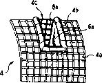
Fig. 4 for only according to the transparent view of the baffle of the arrow that is labeled as IV among Fig. 1,
Fig. 5 is the transparent view according to the baffle of the arrow that is labeled as V among Fig. 1.
The specific embodiment
The figure shows the part of the panelling 1 that the whole width at the passenger space 10 of the occupied vehicle of chaufeur 12 (only showing the thigh and the knee of chaufeur) extends.Only show basically the part of the panelling that relatively extends with chaufeur among Fig. 1.
Panelling 1 comprises the rigid plastic material layer 2 of the main portion of forming panelling.Rigid plastic material layer 2 extends at the whole width of panelling.Its in the zone of the part that the leg with chaufeur relatively extends with the baffle 4 of its covering as lining.
Described baffle has flat basically main portion 4a, forms the protuberance 4c of outshot and the connecting bridge 4b that extends with respect to main portion 4a in the direction towards steering-column tube 14 between main portion 4a and protuberance 4c.Baffle 4 is made up of the single piece of the mono-injection molding that comprises these three parts.
Protuberance 4c has substantially perpendicularly two side 6a, 6b that extend, these two lateral vertical between two legs of main portion 4a at chaufeur from top 8a and below adjacency 8b extending towards the direction of steering-column tube 14.Therefore, the form of protuberance 4c is essentially the half cube cutting on the diagonal line of side 6a, 6b.
Described connecting bridge 4b centers on protuberance 4c extension basically and has the U-shaped cross section.
Baffle 4 has core, and staggered rib 16 stretches out from core on each of the face of core in main portion 4a.Baffle 4 tegillums 2 cover fully, and are fixed to layer 2 by the solder joint that forms between rib 16 and layer 2 in a large number.Because rib 16 is kept substantial constant between the core 28 of baffle 4 and layer 2 in main portion 4a space 30, this assembly is formed bivalve type assembly.
In addition, the protuberance top 8a of 4c and following 8b have staggered rib 18 on the face that is positioned at steering-column tube 14 opposite sides.
The baffle 4 and the 4c that particularly swells extend between steering-column tube 14 and layer 2.In addition, because the described protuberance 4c of baffle 4 is hollow, it defines the space 20 between layer 2 and baffle 4.
Panelling 1 also comprises the directing plate 22 that is fixed to layer 2 and relatively extends with described space 20.As driver's observation, directing plate 22 is protruding basically, so that the knee 12 of chaufeur is split up in the space one of every side of 20.Its for rigidity and stretch out from layer 2, make described layer 2 between space 20 and directing plate 22, extend.In addition, directing plate 22 serves as around the decoration of steering-column tube and thereby is commonly referred to as housing below the bearing circle.
Therefore, under the situation of bump, the knee 12 of chaufeur contacts with panelling, and is relative with the main portion 4a of baffle 4.The rigidity that is fixed to the baffle 4 formed bivalves that provide rib 16 by layer 2 guarantees that the energy of the chaufeur that transmits by knee 12 is distributed to by a baffle 4 and layer 2 assembly that forms partly.
The existence of steering-column tube 14 has limited the counter motion of protuberance 4c under knee 12 effects.Subsequently, baffle 4 distortion, the summit displacement of the U of join domain 4b can not assembled toward each other or towards steering-column tube 14 with two knees 12 guaranteeing chaufeur.
In addition, main portion 4a and layer 2 distortion are to absorb the energy of chaufeur, and protuberance 4c also is such, but degree is lighter.
Unless clash into fiercely unusually, the part of shelf space 20 and this panelling provide the resistance of substantial constant to the knee 12 of chaufeur.
Baffle 4 remains on the structure that is connected to vehicle, particularly is connected between two supporting members 24,26 of crossbeam (not shown).Supporting member 24 directly is fixed to baffle 4, and supporting member 26 is fixed to layer 2 near baffle 4 here.These supporting members 24,26 are partly resisted baffle 4 displacements.Yet they are out of shape to follow the motion of baffle 4 to a certain extent.
Therefore, owing to during bump absorbs, there is the contact between supporting member 24,26 and protuberance 4c and the steering-column tube 14, it is relative with main portion 4a between the strong point 24 and steering-column tube 14 that the left knee of guiding chaufeur keeps, and guides the right knee maintenance of chaufeur relative with main portion 4a between the strong point 26 and steering-column tube 14 simultaneously.
Rigid plastic material layer 2 and baffle 4 are advantageously by the polypropylene manufacturing, and alternatively, this polypropylene is strengthened a little by fiber.Yet existence that must the restriction fiber is affected so that prevent the ductility of rigid plastic material layer 2 and baffle 4, and prevents that them from breaking under the effect of power rather than crooked.
Certainly, the present invention never is limited to the embodiment that has just described by nonrestrictive example.Therefore, rigid plastic material layer 2 may be coated with the outward appearance top layer and be coated with the foamed materials that inserts between rigid plastic material layer and the top layer so that guarantee soft.
In addition, in order to increase the crooked inertia of baffle 4, the profile of this plate can be provided as for example waveform, rather than provide rib for it.
Claims (7)
1. the panelling (1) that is used for the holder's (12) in absorption Vehicular occupant space (10) energy under the situation of bump, this panelling is included in the rigid plastic material layer (2) that the whole width in Vehicular occupant space extends continuously, the rigid plastic material baffle (4) that only on the part of this panelling, relatively extends with the rigid plastic material layer, described baffle (4) has basically the stand away part (4c) of the protuberance that extends of the main portion (4a) of extending contiguously with rigid plastic material layer (2) and formation and rigid plastic material layer (2), so that in the space (20) that in this part of the steering-column tube (14) of vehicle, is provided between baffle (4) and the rigid plastic material layer (2), so that absorb holder's energy by the baffle distortion.
2. panelling according to claim 1 is characterized in that, described baffle (4) also comprise with the protuberance (4c) be connected to main portion (4a) and have the connecting bridge in the cross section of U-shaped (4b) basically.
3. panelling according to claim 1 and 2 is characterized in that, baffle (4) has rib (16,18) on the major part of two face.
4. panelling according to claim 1 and 2, it is characterized in that, baffle (4) has parallel with rigid plastic material layer (2) basically and core (28) that stand away and extend with it in main portion, and baffle (4) arrives rigid plastic material layer (2) at described main portion internal fixation.
5. panelling according to claim 1 and 2 is characterized in that, baffle (4) is made of the single piece of injection molding.
6. panelling according to claim 1 and 2 is characterized in that, it also comprises the rigidity directing plate (22) that is relatively fixed to the rigid plastic material layer with described space (20).
7. equipment is characterized in that according to the vehicle of any one described panelling of aforementioned claim it comprises that two supporting members (24,26) of the structure that is connected to vehicle and baffle remain between these two supporting members.
Applications Claiming Priority (2)
| Application Number | Priority Date | Filing Date | Title |
|---|---|---|---|
| FR0308742 | 2003-07-17 | ||
| FR0308742A FR2857646B1 (en) | 2003-07-17 | 2003-07-17 | DASHBOARD FOR ABSORBING DRIVER ENERGY |
Publications (2)
| Publication Number | Publication Date |
|---|---|
| CN1822970A CN1822970A (en) | 2006-08-23 |
| CN100384663C true CN100384663C (en) | 2008-04-30 |
Family
ID=33548219
Family Applications (1)
| Application Number | Title | Priority Date | Filing Date |
|---|---|---|---|
| CNB2004800206719A Expired - Fee Related CN100384663C (en) | 2003-07-17 | 2004-07-16 | Panel board for absorbing a driver energy |
Country Status (10)
| Country | Link |
|---|---|
| EP (1) | EP1651476B1 (en) |
| CN (1) | CN100384663C (en) |
| AT (1) | ATE349359T1 (en) |
| BR (1) | BRPI0412171B1 (en) |
| DE (1) | DE602004003950T2 (en) |
| ES (1) | ES2279436T3 (en) |
| FR (1) | FR2857646B1 (en) |
| PL (1) | PL1651476T3 (en) |
| RU (1) | RU2334633C2 (en) |
| WO (1) | WO2005009800A1 (en) |
Families Citing this family (3)
| Publication number | Priority date | Publication date | Assignee | Title |
|---|---|---|---|---|
| DE102006048582B4 (en) * | 2006-08-21 | 2010-08-26 | Anatoly Chekaev | The system for increasing the physical safety of occupants of motor vehicles |
| CN105919186A (en) * | 2016-04-19 | 2016-09-07 | 芜湖金鹏汽车部件有限公司 | Safety airbag capable of supporting and protecting legs and having piercing-resisting function |
| FR3100499A1 (en) * | 2019-09-06 | 2021-03-12 | Renault S.A.S | Lower cover for the steering column of a motor vehicle and associated manufacturing process |
Citations (7)
| Publication number | Priority date | Publication date | Assignee | Title |
|---|---|---|---|---|
| US4194762A (en) * | 1977-08-08 | 1980-03-25 | Toyota Jidosha Kogyo Kabushiki Kaisha | Knee protecting device for occupant of vehicle |
| US4349214A (en) * | 1979-02-21 | 1982-09-14 | Nissan Motor Company, Limited | Knee protector |
| US4434999A (en) * | 1980-09-12 | 1984-03-06 | Nissan Motor Co., Ltd. | Leg protector of automotive vehicle |
| US4834422A (en) * | 1986-09-26 | 1989-05-30 | Nissan Motor Co., Ltd. | Knee protective structure of vehicle |
| US5311960A (en) * | 1992-12-17 | 1994-05-17 | Ford Motor Company | Two piece multifunctional composite structural cross vehicular beam |
| US5632507A (en) * | 1995-01-25 | 1997-05-27 | Mercedes-Benz Ag | Vehicle interior support |
| US6145880A (en) * | 1997-12-19 | 2000-11-14 | General Motors Corporation | Knee bolster assembly |
-
2003
- 2003-07-17 FR FR0308742A patent/FR2857646B1/en not_active Expired - Fee Related
-
2004
- 2004-07-16 RU RU2006104843/11A patent/RU2334633C2/en active
- 2004-07-16 WO PCT/FR2004/001889 patent/WO2005009800A1/en active IP Right Grant
- 2004-07-16 PL PL04767713T patent/PL1651476T3/en unknown
- 2004-07-16 ES ES04767713T patent/ES2279436T3/en active Active
- 2004-07-16 EP EP04767713A patent/EP1651476B1/en active Active
- 2004-07-16 BR BRPI0412171A patent/BRPI0412171B1/en not_active IP Right Cessation
- 2004-07-16 AT AT04767713T patent/ATE349359T1/en not_active IP Right Cessation
- 2004-07-16 CN CNB2004800206719A patent/CN100384663C/en not_active Expired - Fee Related
- 2004-07-16 DE DE602004003950T patent/DE602004003950T2/en active Active
Patent Citations (7)
| Publication number | Priority date | Publication date | Assignee | Title |
|---|---|---|---|---|
| US4194762A (en) * | 1977-08-08 | 1980-03-25 | Toyota Jidosha Kogyo Kabushiki Kaisha | Knee protecting device for occupant of vehicle |
| US4349214A (en) * | 1979-02-21 | 1982-09-14 | Nissan Motor Company, Limited | Knee protector |
| US4434999A (en) * | 1980-09-12 | 1984-03-06 | Nissan Motor Co., Ltd. | Leg protector of automotive vehicle |
| US4834422A (en) * | 1986-09-26 | 1989-05-30 | Nissan Motor Co., Ltd. | Knee protective structure of vehicle |
| US5311960A (en) * | 1992-12-17 | 1994-05-17 | Ford Motor Company | Two piece multifunctional composite structural cross vehicular beam |
| US5632507A (en) * | 1995-01-25 | 1997-05-27 | Mercedes-Benz Ag | Vehicle interior support |
| US6145880A (en) * | 1997-12-19 | 2000-11-14 | General Motors Corporation | Knee bolster assembly |
Also Published As
| Publication number | Publication date |
|---|---|
| EP1651476B1 (en) | 2006-12-27 |
| BRPI0412171B1 (en) | 2015-09-22 |
| DE602004003950T2 (en) | 2007-10-11 |
| ATE349359T1 (en) | 2007-01-15 |
| PL1651476T3 (en) | 2007-07-31 |
| FR2857646A1 (en) | 2005-01-21 |
| WO2005009800A1 (en) | 2005-02-03 |
| FR2857646B1 (en) | 2006-02-03 |
| BRPI0412171A (en) | 2006-08-22 |
| RU2334633C2 (en) | 2008-09-27 |
| CN1822970A (en) | 2006-08-23 |
| ES2279436T3 (en) | 2007-08-16 |
| DE602004003950D1 (en) | 2007-02-08 |
| RU2006104843A (en) | 2006-06-27 |
| EP1651476A1 (en) | 2006-05-03 |
Similar Documents
| Publication | Publication Date | Title |
|---|---|---|
| CN101395041B (en) | Bumper system for a motor vehicle | |
| EP1300293B1 (en) | Motor vehicle with bumper assembly for pedestrian protection | |
| US4145081A (en) | Vehicle seat | |
| RU2001134531A (en) | A rail vehicle having a driver’s cab provided with an energy-absorbing structure configured to sense a collision occurring above the vehicle frame | |
| CN101022978A (en) | Reinforcement element for a lower region of a front bumper and front bumper for a motor vehicle provided with the same | |
| KR20040019824A (en) | Rail vehicle | |
| KR101864809B1 (en) | Improved energy absorbing system | |
| JP2004196156A (en) | Vehicle body front structure of automobile | |
| US4427214A (en) | Protective device for motorcycles | |
| EP1133415B1 (en) | Arrangement for occupant protection in vehicles | |
| US20040217605A1 (en) | Passive safety device | |
| CN100384663C (en) | Panel board for absorbing a driver energy | |
| RU2397083C2 (en) | Appliance to protect passenger knees and panel with such appliance | |
| EP2511160B1 (en) | Front unit for a vehicle with shock absorbers and flexible belt | |
| KR101467032B1 (en) | Fiber reinforced plastic bumper back beam and bumper comprise the same | |
| CN106515633A (en) | Bumper energy absorbing buffer structure | |
| EP1322497A1 (en) | A bumper for a vehicle | |
| KR20100010167A (en) | Structure for mounting stiffener of vehicles | |
| CN205706553U (en) | Auxiliary bumper and body construction | |
| CN209757038U (en) | Pedestrian front end protection assembly and vehicle | |
| US20040124667A1 (en) | Bumper device | |
| CN102897137A (en) | Pedestrian protection device for automobile | |
| CN103754189B (en) | The automobile upper leg protection of pedestrian and automobile | |
| CN103085741A (en) | Energy-absorbing block and bumper device provided with same | |
| KR101795070B1 (en) | Walker Injury Protecting Device |
Legal Events
| Date | Code | Title | Description |
|---|---|---|---|
| C06 | Publication | ||
| PB01 | Publication | ||
| C10 | Entry into substantive examination | ||
| SE01 | Entry into force of request for substantive examination | ||
| C14 | Grant of patent or utility model | ||
| GR01 | Patent grant | ||
| CF01 | Termination of patent right due to non-payment of annual fee | ||
| CF01 | Termination of patent right due to non-payment of annual fee |
Granted publication date: 20080430 Termination date: 20180716 |