Embodiment
The present invention is directed to electrostatic drive.Electrostatic drive embodiment as described herein can be used for multiple device, but is proved to be very little Computer Memory Unit and other MEMS system of being used in that be particularly conducive to.Just for the purpose on illustrating, the following stated electrostatic drive embodiment will mainly discuss in the scope of high density MEMS Computer Memory Unit.
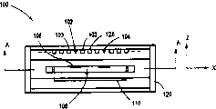
Fig. 1 and Fig. 2 illustrate the side-looking and the top view cross-sectional view of storage device 100 respectively, wherein can adopt according to electrostatic drive of the present invention.Storage device 100 comprises: several field emission utmost points (field emitter), as 102 and 104; Storage medium 106 with memory block of several as 108; And micro-actuator 110, the latter makes storage medium 106 with respect to field emission utmost point scanning (moving) or opposite.Storage device 100 can be configured to each memory block and be responsible for storing 1 or multidigit information.
Field emission extremely can be configured to have the emitter at very sharp-pointed tip.For example, each field emission extremely can have about 1 to hundreds of millimicrons radius of curvature.Duration of work, on the scene causing between emitter and corresponding grid, for example emitter 102 and the circular grid 103 around emitter 102 adds previously selected potential difference.Because the cause of the sharp tip of emitter, electronic beam current are extracted out from emitter and with high accuracy directive memory block.Can come requirement electron-optical system focused beam according to the distance between emitter and the storage medium 106, emitter type and desired spot size (position size).Also can apply voltage or quicken (or deceleration) field emitted electron or help focusing field emitted electron storage medium 106.
Shell 120 is generally suitable for a storage medium 106 and remains on parital vacuum (for example at least 10
-5Torr) in.Researchers have adopted semiconductor processing techniques to produce the field emission utmost point of retrofit in vacuum chamber.Referring to, as " Silicon Field EmissionTransistors and Diodes, " by Jones, published in IEEETransactions on Components, Hybrids and ManufacturingTechnology, 15, page 1051,1992.
Each field emission extremely can be corresponding to one or more memory blocks of setting up on the storage medium 106.If a plurality of memory blocks extremely are responsible in each field emission, then storage device 100 is generally suitable between shell 120 (that is, the field emission utmost point) and storage medium 106 scanning or realizes relative motion with other form.For example, micro-actuator 110 is generally suitable for scanning, make each field emission utmost point to be positioned on the different memory blocks to the diverse location of medium 106.Adopt such structure, micro-actuator 110 can be used for the field emission utmost point (normally two dimension) array on the scan storage media.Because storage medium 106 is with respect to shell 120 motions, so claim that usually it is " mover (mover) ".Accordingly, shell 120 and various other parts (for example field emission utmost point) fixing with respect to shell are commonly referred to " stator (stator) ".
The field emission utmost point is generally suitable for reading and writing information in the memory block by the electron beam that they produce.Therefore, be applicable to that the extremely necessary enough thin electron beam of generation of field emission of storage device 100 is so that obtain required bit density on storage medium 106.And field emission extremely must provide the electron beam with enough power densities so that carry out required read/write operation.Can make this field emission utmost point with several different methods.For example, a kind of method is disclosed in " Physical Properties of Thin-Film Field Emission CathodesWith Molybdenum Cones; " by Spindt et al, publ ished in the Journalof Applied Physics, Vol.47, No.12, December 1976.Another kind method is disclosed in " Fabrication and Characteristics of Si Field EmitterArrays, " by Betsui, published in Tech.Digest 4
ThInt.VacuumMicroelectronics Conf., Nagahama, Japan, Page 26,1991.This class emitter successfully is used in the different application, as flat-panel monitor.
Can provide the field emission utmost point with the form of two-dimensional array (for example 100 * 100 emitters), described array all is 50 microns at x and y direction emitter spacing.Each emitter is can access tens thousand of to several hundred million memory blocks.For example, emitter can scan (being relative motion) on the storage medium with two-dimensional storage district array, gap periods between the wherein adjacent memory block all is from part millimicron to more than 100 or 100 millimicrons anywhere, and the range of operation of micro-actuator all is 50 microns at x and y direction.The field emission utmost point also can be with synchronous or multiplex mode addressing.The parallel addressing scheme provides tangible performance improvement of access time and data rate aspect can for storage device 100.
Fig. 3 is the typical top view of storage medium 106, has described the two-dimensional array of memory block and the two-dimensional array of the field emission utmost point.(not indicating) external circuit is used for the addressable storage district.As shown in the figure, often will be slit into row to memory partitioning, for example row 140, and wherein every row comprises the memory block of some, and for example the memory block 108.Usually, each emitter is responsible for the row of some, but these row of not responsible whole length.For example, as shown in the figure, the memory block that emitter 102 is responsible within row 140 to 142 and the row 144 to 146.
More than the typical storage device of explanation wherein can use according to electrostatic drive of the present invention.The others of this class storage device are disclosed in U.S.Patent No.5557596, and the disclosure of described patent is incorporated herein by this quoting.
Fig. 4 describes according to electrostatic drive 150 of the present invention, and it comprises: the many mover electrodes 152 that are fixed to mover 154 (as storage medium 106); Be fixed to many stator electrodes 156 of stator 158 (as shell 120); And driver 160.Usually, as shown in the figure, mover electrode and stator electrode all are arranged to wire, and be parallel with operation axle (as the x axle).Driver 160 produces voltage on mover electrode and/or stator electrode, thereby produces electrostatic force between mover 154 and stator 158.Since the mechanical suspension effect that the edge effect of electrostatic field and mover and stator coupling adopt, electrostatic force make mover along the x axle with respect to stator movement, as shown in the figure.Change the variation that the voltage be added to electrode produces the relative position of mover and stator.
For obtaining, described axle or direction are repeated as shown in the figure arrangement along the relative motion of another axle (as, y axle) or different directions.For example, as mentioned above, can require storage medium is the x-y plane motion at 2 dimension spaces.Thereby described static driven system will comprise along the mover and the stator electrode of x and y axle.The professional and technical personnel will appreciate that scope of the present invention comprises the system with following ability: produce multi-direction motion, comprise the motion of the direction of straight line/axial motion and direction of a curve or other shape.
In fact can be with various geometric configuration, use the electrode of required any amount.As mentioned above, if axial motion, mover and stator electrode are arranged in the straight line of the kinematic axis that is parallel to requirement usually.And, usually need to set up enough electrodes, make in required whole service scope, at least some movers and stator electrode close enough, form relative motion between the object to produce enough electrostatic force.
For example, specifically referring to Fig. 4, mover electrode 152 is configured to proportional spacing or at interval along the whole effective length of the downside surface of mover 154 basically.Voltmeter on each mover electrode 152 is shown as 1 or 0, and wherein 1 expression electrode is in height (HI) voltage level Ve, and 0 expression electrode is in low (LO) voltage level (being generally ground).As shown in the figure, for adjacent electrode, the voltage on the mover electrode replaces between 1 and 0.Ve is 40 volts and has been proved to be suitable that other level may be suitable for concrete enforcement certainly.In described configuration, the voltage of mover electrode is constant.And, as will explaining, change the voltage on the stator electrode, be used for respect to stator and the electrostatic force of the variation of mobile mover with generation.
Still with reference to figure 4, stator electrode 156 is arranged with similar linear fashion along the surface of the stator 158 of facing mover 154.As the mover electrode, stator electrode 156 is evenly separated usually each other, that is, they have uniform interval.Yet as will seeing, stator electrode may be different from the mover electrode gap at interval.
As shown in the figure, stator electrode 156 is configured to several groups 163, and every group comprises from S0 to S6 totally 7 electrodes.Driver 160 is configured to drive by several different voltage statuss or phase place the electrode of each stator electrode group.These phase places are listed in table 162, and it schematically illustrates and may be added on the stator electrode to produce the voltage of required relative motion.Phase place that every row definition in the table 162 is concrete and expression are added to the voltage level about described phase place of stator electrode S0 to the S6.For example, in the 0th phase, the HI voltage level (as, Ve represents with 1 in table) be added to stator electrode S0, LO voltage level (as ground) is added to stator electrode S1, and the rest may be inferred.As shown in the figure, stator electrode has 14 different phase places; In table, these phase places are designated as from 0 to 13.Transformation from a phase place to its adjacent phase (phase place that promptly rises or the phase place that descends) causes that mover 154 moves a fixed step size with respect to stator 158.
As with shown in the bus type line 164, be added to every group of 7 stator electrodes that are positioned on the stator usually by 0 and 1 voltage pattern to the phase bit definition.Therefore, should be pointed out that stator electrode be logic groups be again physical packets.Because every group is included in 7 adjacent stator electrodes of physics on the stator, so all stator electrodes physically divide into groups.Because in the electrode surface length range, similarly repeat electroactive, 7 one group be the grouping of stator electrode minimum, so all stator electrodes divide into groups in logic.Every group from the identical set of signals of driver 160 receptions.
To each group 163 of 7 stator electrodes, 6 mover electrodes of the equal length of occupying are arranged, as shown in the figure on mover.So the spacing of stator electrode is 6/7 of a mover electrode.Can adopt other block form and spacing ration.For example, system can be configured to the logic groups of stator electrode formation greater or less than 7 electrodes.The spacing ration of stator electrode and mover electrode can be 1: 1 or shown in other value outside 7: 6 ratios of example.
Although have many configurations,, like that, wish that usually stator-mover spacing ration is (n): (n-1), wherein n is the stator electrode number of each logical group in the as directed example.The geometry of the mover step-length servo-actuated sub-electrode that usually, pushes away before each phase place and the relative force constant of motor elastic force and static driven and become.To point out that below to above-mentioned (n): stator (n-1)-mover spacing ration, the fixed step size that each transformation of adjacent phase produces equals the stator electrode number of the spacing of mover electrode divided by every logical group.The electrostatic force that produces between this supposition electrode is much larger than the elastic force of motor.For example, suppose that the mover electrode spacing is 1.4 microns and every group of 7 stator electrodes, so, step-length will be 0.2 micron.Therefore, referring to table 162, from phase place 5 to or phase place 4 or phase place 6 change the axial relative displacement of x that the stator electrode voltages can cause mover 154 and the stator 158 0.2 micron.In fact, in this example,, increase or reduce a HI voltage phase place and will form 0.2 micron displacement from the arbitrary phase of 14 outs of phase shown in the table 162.
In many cases, the step-length by above-mentioned geometric electrode structures shape is enough.In other cases, need to improve the resolving power (for example, by reducing step-length) of mover.For example, as an embodiment of storage device as described in Fig. 1-3, the data track on the storage medium is 40 millimicrons wide, or in the above-mentioned example 0.2 micron step-length 1/5.Be the data track of this size of addressing accurately, need be than 0.2 micron much higher mover resolving power.Allow effectively to adopt closed loop servo control, reduce quantization error and allow storage device with the location of high-resolution more with trajector deviation adjustment mode work (as the data recovery operation often requires).
Still, the system and method that improves the mover resolving power is described with reference to figure 4.Usually, the proportional control by the voltage on one or more stator electrodes 156 reduces step-length.Have been found that the voltage that changes a stator electrode at (promptly 0 and Ve between) between low (LO) and high (HI) voltage signal, cause the linear in proportion conversion of step-length.For example, suppose to phase place 1 (stator electrode S0 to the level of S6=0010101} is as table 162 finding), mover is in x=0 micron position.Suppose aforesaid step-length, switch to phase place 2 (S0 is to S6={0110101}) and can make mover advance to the x=0.2 micron.Also can be in proportion do not increase to 1 from 0 if do not advance to voltage on phase place 2, the 2 stator electrodes (S1), it is constant that all other stator electrodes keep the value of phase places 1 simultaneously, to obtain meticulousr Position Control.Like this, by stator electrode is set in S0 to S6={0110101}, can realize the Position Control of 10% (x=0.02 micron) of fixed step size.This is appreciated that paired phase place 1 " modification ".
This result can more generally expand to described system, wherein carries out proportional control by a stator electrode to every group of stator electrode and improves resolving power.Shown in table 162 dotted line, the ratio electrode switches with phase place propelling each time.S0 is carried out the proportional control of 0 phase place, SI is carried out the proportional control of phase place 1, S2 is carried out the proportional control of phase place 2, the rest may be inferred.Usually, shown in table 162, the ratio electrode equals (phase mode 7 (phase mod 7)).Therefore, in case phase place determines that the stator electrode that will control can be determined with the hardware or the software of mould 7 logics simply.
Fig. 5 explanation voltage waveform of each in 7 stator electrodes in concrete stator electrode group.Because systemic circulation so each stator electrode is in low level (0) during 6 continuous phase places, is in transition stage through in 14 outs of phase each during 1 phase place, during 6 continuous phase places, be in high level (1) then.Described waveform shows that the linear oblique wave between low and the high level changes, and is illustrated in to take place during the phase place that oblique wave changes given stator electrode to be carried out proportional control.
For example, in phase place 9, electrode S2 is to high level by proportional control from low level and change.During described phase place, S2 is set to certain ratio value between low level and the high level by ratio, and to realize required displacement, all other electrode remains on LO and the HI voltage level that phase place 9 is determined simultaneously.Equally, this is appreciated that the modification of paired phase place 9.When S2 is made as 0 (low level), phase place 9 is not left the modification of voltage status shown in Fig. 4 table 162.When increasing voltage on the S2 and revise phase place 9, the proportional quantities that is subjected to displacement, that is, and with proportional by being converted to the fixed step size that phase place 10 takes place from phase place 9 simply.When the voltage on the S2 reaches 1 (high level), a certain amount of displacement takes place, described displacement approaches described phase place and switches to the displacement that phase place 10 can take place simply.Further displacement if desired, electrode voltage switches to the level of phase place 10 appointments, and the ratio electrode switches to S3, then the latter is carried out proportional control to realize required displacement.
Therefore, will point out below,, need two kinds of information at least in order to locate mover.It at first is phase place.As mentioned above, which electrode of phase decision is wanted proportional control, and is to be added on remaining disproportional electrode high level or low level.Second information is will be added to the ratio electrode to produce the voltage of required mover displacement.
These two kinds of information can be synthesized in the long number instruction, and as typical control instruction 170, it comprises integer value 172 and fractional value 174.The phase place step number (phase place advances the displacement that produces) that integer value 172 specifies mover to move from certain reference point.In above-mentioned example, each phase step provides 0.2 micron displacement.Described integer value 172 is 8 figure places, so 256 phase step of outfit as many as.Suppose that step-length is above-mentioned 0.2 micron, this can provide the relative displacement of about 50 microns ranges of operation.It is useful that this scope has been proved to be above-mentioned typical storage devices.Certainly, can revise described integer codomain step-length so that hold the phase step of required arbitrary number.
Usually handle integer value 172 so that produce 4 place values, described value is specified the phase place of stator electrode.This can be by utilize realizing mould 14 counters hardware or software integer value 172 be transformed into 14 system numbers finish.On the other hand, described integer value also can directly be transformed into phase place by one of following 14 system conversion methods: (1) phase place=iv-INT (iv/14) * 14, and wherein iv is described integer value; Perhaps, (2) phase place=iv-INT ((iv*64+iv*8+iv+72)/1024) * 14.
For mover being moved requisite number purpose phase step, driver 160 makes stator electrode 156 cycle through all continuous phases therebetween usually.In order to illustrate, suppose that integer value 172 is that 0 o'clock mover is in the x=0 position.When integer value 172 was 50, mover moved on to x=50* (0.2)=10 micron.Also be that stator electrode is at phase place 8 (S0 is to S6={1101010}) described point (being the x=10 micron).For mover being moved again 10 microns, need to increase by 50 phase step to the x=20 micron.Therefore, from phase place 8, phase place increases (from phase place 8 to phase place 9,10,11,12,13,0,1, or the like) 50 times, realizes required moving to produce necessary electrostatic force.In the 100th step, electrode is in phase place 2.
Fractional value 174 is assigned to the fractional value of phase bit step-length, and is used to determine to be added to the ratio of the voltage of the electrode that is subjected to proportional control.Another method of considering fractional value 174 is that it is revising what explanation from the unmodified expression shown in the table 162 to phase bit.In described control command 170, adopt 12 fractional values, produce final step-length, the latter is than advancing the basic step-length that produces little 4096 times by phase place.Thereby if adopt 0.2 micron step-length in the above-mentioned example, 12 fractional values provide and reach 0.05 millimicron (0.2/4096 micron), i.e. 1/20 millimicron mover resolving power.
To point out that below aforementioned proportion control system and control command provide certain superiority.An advantage is an easy operating.In some sense, described system produces the effect of digital-to-analog converter, and it receives numeral input (as control command 170) and correspondingly produces simulation output (as the physical displacement of mover 154).The physical displacement amount is easy to control, because it is with the digital input value linear change.Control command allows the easy programming Control of the programmer/designer of system to move and needn't know the internal mechanical details of movable system.In addition, described proportional control scheme strengthens Motion Resolution power, does not need supplemantary electrode or complicated support electronic circuit.
Fig. 6 describes the various parts of driver 160, and described driver can be used for producing voltage required on the stator electrode 156.For each stator electrode is provided with half bridge circuit 180.Each half bridge circuit comprises: input grid 182, and it is connected to p type field effect transistor 184 and n type field effect transistor 186, and the latter links to each other with ground with Ve respectively; And the output pin 188 of stator electrode voltage.Be provided with and regulate operational amplifier 190 and realize proportional control one of described electrode (as the oblique electrode that is subjected to proportional control of dotted line appointment in the table 162).Voltage divider 192 (resistance 194 and 196) and D-A converter 198 are connected to the input of operational amplifier.Electrode table 162 and the described epiphase of Fig. 4 comprise the level that is added to different stator electrodes together.Driver 160 can also comprise that processor 202, memory 204 and configuration realize other hardware and software parts of function described herein.
As mentioned above, control command 170 is added to driver 160 as input signal.As previously mentioned, integer value 172 designated phase number and phase places, the latter is for reaching the moving of command request, phase place that stator electrode must place.Based on described phase place, know the voltage that will be added on the disproportional stator electrode.Usually, the numerical value according to storage applies these voltage, the numerical value for out of phase shown in (Fig. 4) in the table 162.Phase place selects to produce the input signal that is input to the disproportional electrode that will switch, so that storing value is added to the half bridge circuit of the described electrode output of control as input signal.Specifically, perhaps 1 or the 0 input grid 182 that is added to the half bridge circuit of each disproportional electrode.Add 1 place, p type field effect transistor 184 is saturated, and electrode output lead 188 is connected to Ve.If 0 is added to grid, then n type field effect transistor 186 is saturated, described electrode output lead ground connection.
Phase value also determines the switching of the input signal of described ratio electrode.Specifically, which half bridge circuit of phase decision is connected with adjusting operational amplifier 190 selected, so that in the output generation ground of half bridge circuit and the output between the Ve.Select based on phase place, the input grid 182 of selected half bridge circuit is connected to the output 208 of operational amplifier 190.The output lead 188 of selected half bridge circuit is connected to the input of operational amplifier 190 by resistance 196.
Output by input 210 is provided to D-A converter 198 at selected half bridge circuit produces required ratio-voltage.Input 210 is set in: perhaps (1) fv/4096, and wherein fv is fractional value 174 (supposition fractional value 174 is 12 figure places); Perhaps (2) 1-fv/4096.Both of these case reflects respectively: sometimes increase displacement (the 1st kind of situation) by the voltage that improves on the ratio electrode; And increase displacement (the 2nd kind of situation) by the voltage that reduces on the ratio electrode under other situation.Referring to Fig. 5 voltage waveform, when the transformation slope was positive (when Fig. 4 electrode input item is 0), D-A converter 198 provided fv/4096 (the 1st kind of situation).When the transformation slope was (when Fig. 4 electrode input item is 1) who bears, D-A converter 198 provided 1-fv/4096 (the 2nd kind of situation).
Analog output signal from D-A converter 198 is added to operational amplifier 190 as input signal via positive input terminal, and the dividing potential drop output from selected half bridge circuit simultaneously is added to operational amplifier 190 via negative input end.Apply these input signals and finally make operational amplifier 190 reach balance, at this moment, required ratio-voltage is from selected half bridge circuit output and be added to given stator electrode.
Believe a plurality of unique invention that includes independent utility in above-mentioned the disclosing.Though these invent each with its preferred form openly, in the time may having a large amount of modification, specific embodiment open at this and explanation is not seen as the tool limited significance.Main aspect of the present invention comprises novel and non-obvious all combinations and the sub-portfolio of different elements disclosed herein, feature, function and/or performance.Similarly, claims statements " one " or " first " element or its equivalents, its claims are understood to include one or more these combination of elements, rather than will get rid of and comprise two or more these elements.
Believe that subsequently claims have specifically noted some combination and sub-portfolio, the latter at one of invention of the present disclosure and be novel with non-obvious.Being included in other combination of feature, function, element and/or performance and the invention in the sub-portfolio can be by revising these claims or (at new claims of this or related application) explanation is applied for a patent.Whether this class is revised or new claims, different, wideer, narrower or equal the scope of original rights claim no matter whether it is at difference invention or same invention, also is understood as that to be included in the subject matter of an invention of the present disclosure.