CN100366373C - Double constant current and its self-optimization control method for intelligent inverter welding machine - Google Patents
Double constant current and its self-optimization control method for intelligent inverter welding machine Download PDFInfo
- Publication number
- CN100366373C CN100366373C CNB031279619A CN03127961A CN100366373C CN 100366373 C CN100366373 C CN 100366373C CN B031279619 A CNB031279619 A CN B031279619A CN 03127961 A CN03127961 A CN 03127961A CN 100366373 C CN100366373 C CN 100366373C
- Authority
- CN
- China
- Prior art keywords
- current
- welding
- self
- value
- circuit
- Prior art date
- Legal status (The legal status is an assumption and is not a legal conclusion. Google has not performed a legal analysis and makes no representation as to the accuracy of the status listed.)
- Expired - Fee Related
Links
- 238000003466 welding Methods 0.000 title claims abstract description 126
- 238000000034 method Methods 0.000 title claims abstract description 88
- 238000005457 optimization Methods 0.000 title claims description 23
- 230000007704 transition Effects 0.000 claims description 18
- 238000002844 melting Methods 0.000 claims description 8
- 230000008018 melting Effects 0.000 claims description 8
- 238000005070 sampling Methods 0.000 claims description 6
- 230000008859 change Effects 0.000 claims description 5
- 230000009977 dual effect Effects 0.000 claims description 5
- 239000006185 dispersion Substances 0.000 claims description 4
- 230000033228 biological regulation Effects 0.000 claims description 2
- 230000004044 response Effects 0.000 claims description 2
- 238000004519 manufacturing process Methods 0.000 claims 1
- 230000008569 process Effects 0.000 abstract description 50
- 238000012360 testing method Methods 0.000 description 7
- 238000012546 transfer Methods 0.000 description 6
- 239000007789 gas Substances 0.000 description 5
- 230000015572 biosynthetic process Effects 0.000 description 4
- 230000000694 effects Effects 0.000 description 4
- 238000005516 engineering process Methods 0.000 description 4
- 230000008901 benefit Effects 0.000 description 2
- 238000011161 development Methods 0.000 description 2
- 238000010586 diagram Methods 0.000 description 2
- 238000009826 distribution Methods 0.000 description 2
- 238000011156 evaluation Methods 0.000 description 2
- 239000007788 liquid Substances 0.000 description 2
- 230000007246 mechanism Effects 0.000 description 2
- 238000013139 quantization Methods 0.000 description 2
- 238000011160 research Methods 0.000 description 2
- UFHFLCQGNIYNRP-UHFFFAOYSA-N Hydrogen Chemical compound [H][H] UFHFLCQGNIYNRP-UHFFFAOYSA-N 0.000 description 1
- 229910001209 Low-carbon steel Inorganic materials 0.000 description 1
- 230000009471 action Effects 0.000 description 1
- 238000004458 analytical method Methods 0.000 description 1
- 239000011324 bead Substances 0.000 description 1
- 238000005422 blasting Methods 0.000 description 1
- 238000001311 chemical methods and process Methods 0.000 description 1
- 230000006835 compression Effects 0.000 description 1
- 238000007906 compression Methods 0.000 description 1
- 230000008602 contraction Effects 0.000 description 1
- 230000007423 decrease Effects 0.000 description 1
- 238000001514 detection method Methods 0.000 description 1
- 238000004880 explosion Methods 0.000 description 1
- 230000004907 flux Effects 0.000 description 1
- 230000005484 gravity Effects 0.000 description 1
- 229910052739 hydrogen Inorganic materials 0.000 description 1
- 239000001257 hydrogen Substances 0.000 description 1
- 230000006872 improvement Effects 0.000 description 1
- JEIPFZHSYJVQDO-UHFFFAOYSA-N iron(III) oxide Inorganic materials O=[Fe]O[Fe]=O JEIPFZHSYJVQDO-UHFFFAOYSA-N 0.000 description 1
- 239000011159 matrix material Substances 0.000 description 1
- 238000005259 measurement Methods 0.000 description 1
- 239000000155 melt Substances 0.000 description 1
- 239000002184 metal Substances 0.000 description 1
- 230000010355 oscillation Effects 0.000 description 1
- 238000004886 process control Methods 0.000 description 1
- 238000004445 quantitative analysis Methods 0.000 description 1
- 230000009467 reduction Effects 0.000 description 1
- 230000008439 repair process Effects 0.000 description 1
- 230000000630 rising effect Effects 0.000 description 1
- 230000035945 sensitivity Effects 0.000 description 1
- 238000007493 shaping process Methods 0.000 description 1
- 239000000779 smoke Substances 0.000 description 1
- 239000007787 solid Substances 0.000 description 1
- 230000001052 transient effect Effects 0.000 description 1
Images
Landscapes
- Arc Welding Control (AREA)
Abstract
Description
技术领域 technical field
本发明涉及一种逆变焊机的智能自寻优的控制方法,尤指在焊接过程中能自寻优模糊控制电流波形,根据电流的设定值自动调节基值与峰值电流,以改善焊缝成型,减少焊接飞溅。The invention relates to an intelligent self-optimizing control method for an inverter welding machine, especially refers to the ability to self-optimize the fuzzy control current waveform during the welding process, and automatically adjust the base value and peak current according to the set value of the current to improve welding. Seam forming reduces weld spatter.
背景技术 Background technique
CO2气体保护焊是一种高效节能、低氢抗锈、具有较高综合经济效益的焊接方法。但存在着飞溅大、成形差的缺点,从而制约了它的进一步推广和应用。迄今为止始终不能从根本上解决CO2气体保护焊接飞溅大、成形差的缺点。究其原因,主要是对焊接过程中各状态参数间的相互制约和内在联系始终没有找到一个好的描述方法。当前,对反映焊接过程状态的各特征参数的分析和描述是局部的、且相互间没有联系,因此无法对焊接短路过渡过程的状态进行综合分析和评判,因而把这些单指标特征参数作为CO2焊接过程控制的直接依据,就难以获得满意的工作状态,也就无法从根本上解决CO2焊接飞溅大、成形差的问题。鉴于CO2焊接过程比较复杂,以往一般均以CO2焊接熔滴短路过渡频率来作为定量分析的特征值,显然是不足以全面描述CO2焊接过程的本质。CO 2 gas shielded welding is a welding method with high efficiency, energy saving, low hydrogen and rust resistance, and high comprehensive economic benefits. However, it has the disadvantages of large splash and poor forming, which restricts its further promotion and application. So far, the shortcomings of large spatter and poor forming of CO 2 gas shielded welding have not been fundamentally solved. The reason is mainly that a good description method has not been found for the mutual constraints and internal relations among the various state parameters in the welding process. At present, the analysis and description of the characteristic parameters reflecting the state of the welding process are partial and not related to each other, so it is impossible to comprehensively analyze and judge the state of the welding short-circuit transition process. Therefore, these single-index characteristic parameters are regarded as CO 2 If the direct basis of welding process control, it is difficult to obtain a satisfactory working state, and it is impossible to fundamentally solve the problems of large CO 2 welding spatter and poor forming. In view of the complexity of the CO 2 welding process, the short-circuit transition frequency of CO 2 welding droplets is generally used as the characteristic value of quantitative analysis in the past, which is obviously not enough to fully describe the essence of the CO 2 welding process.
为改善CO2弧焊短路过渡过程的动特性,人们试图通过控制短路过渡时的电流、电压波形,使熔滴顺利地进入熔池,从而减少飞溅,改善焊缝成形。随着控制技术及对飞溅机理认识的不断深入,人们已认识到必须在熔滴过渡的不同时刻迅速进行相应的控制,满足过渡熔滴的受力和受热的不同需要,这样才能既保证稳定的过渡过程又可最大限度地减少飞溅。通常在颈缩形成过程,提高电流上升速度,促进颈缩形成;而在短路过渡后期,降低电流,使液桥爆破在低的能量下完成,获得无飞溅的短路过渡过程。这方面有代表性的弧焊电源是美国林肯公司的表面张力过渡电源。此电源将短路过渡过程细分为六个阶段加以控制。由此得到了少飞溅甚至无飞溅的焊接,焊缝成形美观,烟尘少。In order to improve the dynamic characteristics of the CO 2 arc welding short-circuit transition process, people try to control the current and voltage waveforms during the short-circuit transition to make the droplet enter the molten pool smoothly, thereby reducing spatter and improving weld formation. With the deepening of the control technology and the understanding of the splash mechanism, people have realized that it is necessary to quickly carry out corresponding control at different moments of the droplet transfer to meet the different needs of the force and heat of the transfer droplet, so as to ensure a stable flow. The transition process again minimizes splashing. Usually, in the process of necking formation, the current rising speed is increased to promote the formation of necking; and in the later stage of short circuit transition, the current is reduced, so that the liquid bridge blasting can be completed at low energy, and a short circuit transition process without splash is obtained. The representative arc welding power source in this respect is the surface tension transition power source of American Lincoln Company. This power supply subdivides the short-circuit transition process into six stages for control. The result is spatter-less or even spatter-free welding with beautifully formed welds and less smoke.
但是焊接过程本身是一个非常复杂的物理和化学过程,影响焊接质量的因素很多。美国林肯公司的精细的波形控制方法在大大提高了对熔滴过渡的控制能力的同时也带来了可控参数的增多;而日立公司的电流波形控制电源,可控参数则多达14个。这些公司全部都用硬件完成,控制电路复杂,这不仅影响了系统的可靠性,使参数调整和控制极不灵活,而且更重要的是其参数不能根据焊接过程的变化进行自适应优化和调整。这一方面不便于焊工的操作,另一方面也不利于焊接性能的进一步提高,因而无法在最大程度上改善焊接电源的动特性。But the welding process itself is a very complicated physical and chemical process, and there are many factors that affect the welding quality. The fine waveform control method of American Lincoln Company has greatly improved the ability to control the droplet transfer and also brought more controllable parameters; while Hitachi's current waveform control power supply has as many as 14 controllable parameters. These companies all use hardware to complete, and the control circuit is complex, which not only affects the reliability of the system, makes parameter adjustment and control extremely inflexible, but more importantly, its parameters cannot be adaptively optimized and adjusted according to changes in the welding process. On the one hand, this is inconvenient for welders to operate, and on the other hand, it is not conducive to the further improvement of welding performance, so the dynamic characteristics of the welding power source cannot be improved to the greatest extent.
随着电力电子技术和微机控制技术的迅猛发展,加速了新型微机控制焊机的研究进程。C02气体保护焊机如能通过自适应控制电流波形等参数会在最大程度上改善电源动特性。With the rapid development of power electronics technology and microcomputer control technology, the research process of new microcomputer control welding machine has been accelerated. If the C02 gas shielded welding machine can control the current waveform and other parameters adaptively, the dynamic characteristics of the power supply will be improved to the greatest extent.
发明内容 Contents of the invention
根据背景技术所述,本发明的目的在于提供一种根据焊接电流的设定值和电弧状态自动确定不同阶段的电源外特性,并快速切换焊接电流以响应电弧变化和焊接电流的设定,为此,采用双恒流或多恒流控制模型的自寻优智能控制的方法。控制其表征短路过渡综合性能的综合值为目标函数,通过控制短路和燃弧各阶段的电流,电压波形,使规范参数达到最佳匹配,实现焊接过程熔滴的可控过渡,提高熔滴过渡的稳定性,进一步改善焊接过程的综合性能。According to the background technology, the object of the present invention is to provide a method to automatically determine the external characteristics of the power supply at different stages according to the set value of the welding current and the state of the arc, and quickly switch the welding current to respond to the arc change and the setting of the welding current. Therefore, the self-optimizing intelligent control method of double constant current or multi-constant current control model is adopted. Control the comprehensive value representing the comprehensive performance of the short-circuit transition as the objective function. By controlling the current and voltage waveforms of each stage of the short-circuit and arcing, the specification parameters can be optimally matched, and the controllable transfer of the droplet in the welding process can be realized, and the transfer of the droplet can be improved. stability, further improving the overall performance of the welding process.
为了实现上述目的,本发明是通过以下技术方案来实现的:In order to achieve the above object, the present invention is achieved through the following technical solutions:
一种智能逆变焊机双恒流及其自寻优控制方法,主要包括智能控制焊接规范和自寻优模糊控制电流波形,它能根据焊接电流的设定值和电弧状态,自动确定不同阶段的电源外特性,根据电弧状态检测焊接电流,弧压,短路过渡频率,以及短路,燃弧能量等参数,采用双恒流或多恒流自动快速切换焊接电流以响应电弧变化和焊接电流的设定,实现自寻优智能控制,其特征在于:An intelligent inverter welding machine double constant current and its self-optimization control method, mainly including intelligent control welding specification and self-optimization fuzzy control current waveform, which can automatically determine different stages according to the set value of welding current and arc state The external characteristics of the power supply, according to the arc state detection welding current, arc voltage, short-circuit transition frequency, and short-circuit, arc energy and other parameters, adopt double constant current or multi-constant current to automatically and quickly switch welding current to respond to arc changes and welding current settings Determined to realize self-optimization intelligent control, which is characterized in that:
(1)由焊工给定焊接电流的初始值,由单片机自动给定波形参数和送丝速度的初始值;(1) The initial value of the welding current is given by the welder, and the waveform parameters and the initial value of the wire feeding speed are automatically given by the single-chip microcomputer;
(2)电流波形按照短路初期,短路末期与燃弧初期,燃弧峰值电流,基值电流进行控制切换,通过基值电流控制焊丝熔化率和焊缝成型,通过峰值电流控制熔化率,通过智能自寻优来实现峰值,峰值时间,基值,以及电流峰值和基值的比值以最佳匹配,使焊接电流与熔化率达到最佳匹配,以短路初期,短路末期和燃弧初期的恒流来抑制飞溅;(2) The current waveform is controlled and switched according to the initial stage of short circuit, the end stage of short circuit and the initial stage of arcing, the peak value of arcing current, and the base value current. The melting rate of the welding wire and the shape of the weld are controlled by the base value current. Self-optimization to achieve the peak value, peak time, base value, and the ratio of the current peak value to the base value to achieve the best match, so that the welding current and melting rate can achieve the best match, and the constant current at the initial stage of short circuit, the end of short circuit and the initial stage of arc ignition to suppress splashing;
(3)焊接电流自寻优模糊控制的目标函数为特征参数的综合值G(I),在焊接电流I值临域进行微调,即(3) The objective function of the welding current self-optimization fuzzy control is the comprehensive value G(I) of the characteristic parameters, which is fine-tuned in the critical area of the welding current I value, namely
式中:fd-短路频率,σ-短路周期的分散性指标,In the formula: f d - short circuit frequency, σ - dispersion index of short circuit period,
Tas-燃弧时间与短路比值T as - arcing time to short circuit ratio
Qfd,Qσ,Qtas--各特征参数的期望值Q fd , Q σ , Q tas -- the expected value of each characteristic parameter
Kσ,Kas--特征参数σ,Tas相对fd的权重系数K σ , K as --the characteristic parameter σ, the weight coefficient of T as relative to f d
(4)恒流电路由硬件PI反馈电路实现,电流给定由单片机实现,由软件实现不同恒流值的给定,硬件恒流模块则完成电流的PI调节。(4) The constant current circuit is realized by the hardware PI feedback circuit, the current setting is realized by the single chip microcomputer, the setting of different constant current values is realized by the software, and the hardware constant current module completes the PI adjustment of the current.
由于采用了上述技术方案,本发明具有以下优点和效果:Owing to adopting above-mentioned technical scheme, the present invention has following advantage and effect:
1、本发明可根据焊接过程中各主要特征参数的综合评价结果来自寻优控制焊接规范和波形参数,自动将可控参数自动调节到最佳,本发明的控制方法显著地改善了弧焊的电源动态性能,焊缝成型和减少焊接飞溅;1. The present invention can automatically adjust the controllable parameters to the best according to the comprehensive evaluation results of the main characteristic parameters in the welding process from the optimal control welding specification and waveform parameters. The control method of the present invention significantly improves the arc welding performance. Power dynamics, weld bead shaping and weld spatter reduction;
2、本发明控制参数调整和控制极为灵活,控制参数数量适中,而且便于焊工操作和理解,也为今后更进一步的发展奠定了良好的基础;2. The adjustment and control of the control parameters of the present invention are extremely flexible, the number of control parameters is moderate, and it is easy for welders to operate and understand, and it also lays a good foundation for further development in the future;
3、本发明可制成一智能控制盒嵌入普通逆变焊机电源内。3. The present invention can be made into an intelligent control box embedded in a common inverter welding machine power supply.
附图说明 Description of drawings
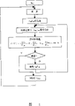
图1为本发明控制方法的流程图Fig. 1 is the flowchart of control method of the present invention
图2为本发明控制方法原理框图Fig. 2 is a functional block diagram of the control method of the present invention
图3为本发明双恒流控制原理示意图Fig. 3 is a schematic diagram of the double constant current control principle of the present invention
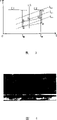
图4为本发明实施例焊接件的照片Fig. 4 is the photo of the weldment of the embodiment of the present invention
具体实施方式 Detailed ways
参见图1,图2,智能逆变焊机的工作过程是:See Figure 1 and Figure 2, the working process of the smart inverter welding machine is:
对于焊接电流小于180A-200A时,采用短路、燃弧峰值与基值三恒流控制法。开始时,加以一定的与送丝速度匹配的基值电流,使得在焊丝末端维持一个1.2倍于焊丝直径的球状熔滴并控制熔滴直径,以防止熔滴直径太小时电弧不稳,太大时产生飞溅。在熔滴刚接触到熔池时,将焊接电流在0.8ms内下降到很低水平,减少短路小桥的能量,形成小桥后,电流受控上升到一个较大的电流值,使小桥在一个较大的压力(电磁收缩力、重力等)下缩颈。缩颈使得电流流经面积急剧减小,电流密度显著增加。在小桥将要断开的时候,在数微秒内将电流减少,熔滴在表面张力作用下无飞溅地过渡到熔池,此时焊丝端头脱离熔池,形成电弧空间,然后电源输出一个大电流,一方面使焊丝端头熔化,并形成一定尺寸的熔滴,另一方面大电流电弧产生一个向下的电弧压力施加于熔池表面,使焊缝熔池形成一定的形状。上述过程由本发明控制方法实现。对电流波形控制按照短路初期、短路末期与燃弧初期、燃弧峰值电流、基值电流进行切换。通过基值电流以控制焊丝基本熔化率和焊缝成型,通过峰值电流控制熔化率,通过智能自寻优来实现峰值、峰值时间、基值,以及蜂值基值的比值自寻优的最佳匹配,控制并使焊接电流与熔化率达到匹配最佳。同时通过短路初期、短路末期和燃弧初期的恒流控制来抑制飞溅。如此周而复始地进行,使我们得到较佳的CO2焊接工艺。When the welding current is less than 180A-200A, the three constant current control methods of short circuit, arc peak value and base value are adopted. At the beginning, add a certain base value current that matches the wire feeding speed, so that a spherical droplet 1.2 times the diameter of the welding wire is maintained at the end of the welding wire and the diameter of the droplet is controlled to prevent the arc from being unstable if the droplet diameter is too small. When splashing occurs. When the droplet just touches the molten pool, the welding current is lowered to a very low level within 0.8ms to reduce the energy of the short-circuit bridge. After the bridge is formed, the current is controlled to rise to a larger current value to make the bridge Necking under a greater pressure (electromagnetic contraction force, gravity, etc.). Necking makes the current flow area sharply reduced, and the current density increases significantly. When the small bridge is about to be disconnected, the current is reduced within a few microseconds, and the droplet transitions to the molten pool without splashing under the action of surface tension. At this time, the end of the welding wire leaves the molten pool to form an arc space, and then the power supply outputs a The high current, on the one hand, melts the end of the welding wire and forms droplets of a certain size. On the other hand, the high-current arc generates a downward arc pressure that is applied to the surface of the molten pool to form a certain shape of the weld pool. The above process is realized by the control method of the present invention. The current waveform control is switched according to the initial stage of short circuit, the end stage of short circuit and the initial stage of arcing, the peak value of arcing current, and the base value current. The base current is used to control the basic melting rate of the welding wire and the weld shape, and the peak current is used to control the melting rate. Through intelligent self-optimization, the peak value, peak time, base value, and the ratio of bee value to the base value are self-optimized. Match, control and make the best match between welding current and melting rate. At the same time, spatter is suppressed by constant current control at the initial stage of the short circuit, at the end of the short circuit, and at the initial stage of arcing. Carrying out such a cycle allows us to obtain a better CO 2 welding process.
本发明采用的自寻优模糊控制方法是:The self-seeking optimal fuzzy control method that the present invention adopts is:
本发明将反映综合性能的目标函数增量ΔF、寻优步长ΔI(电流增量)作为模糊变量。自寻优模糊控制的工作过程如下。In the present invention, the objective function increment ΔF and the optimization step ΔI (current increment) reflecting comprehensive performance are taken as fuzzy variables. The working process of self-optimizing fuzzy control is as follows.
(1)首先将试验得到初选推荐值作为寻优起点,在焊接电流推荐值附近约束范围内,在每个控制周期(2s)内计算特征参数采样值,根据特征参数采样值求目标函数增量ΔF。该法系在初选推弃值附近给定允许区域的最大值寻优,可避免焊接过程的失稳,对焊接过程是否收敛的问题并不敏感。(1) First, take the primary recommended value obtained from the test as the starting point for optimization, calculate the sampled value of the characteristic parameter in each control cycle (2s) within the constraint range near the recommended value of the welding current, and calculate the increase in the objective function according to the sampled value of the characteristic parameter The amount ΔF. This method optimizes the maximum value of the allowable area around the primary rejection value, which can avoid the instability of the welding process and is not sensitive to the convergence of the welding process.
(2)模糊自寻优根据ΔI和ΔF/ΔI的大小、正负确定搜寻方向和步长。并根据性能增量ΔF和上一周期寻优步长ΔIK-1决定本次寻优步长ΔIK,对焊接电流在线实时微调,使目标函数趋于极值。(2) Fuzzy self-optimization determines the search direction and step size according to the size, positive or negative of ΔI and ΔF/ΔI. And according to the performance increment ΔF and the optimization step ΔI K-1 of the previous cycle, the optimization step ΔI K of this time is determined, and the welding current is fine-tuned online in real time, so that the objective function tends to the extreme value.
(3)当目标函数达到极值点时,保持输出不变。(3) When the objective function reaches the extreme point, keep the output unchanged.
(4)如目标函数未达到极值点,则继续对焊接电流自寻优模糊调节,直到目标函数达到极值点。(4) If the objective function does not reach the extremum point, continue to self-optimize the fuzzy adjustment of the welding current until the objective function reaches the extremum point.
(5)由于采样数据的分散性,不同时段可得到不同的极值点,记忆各极值点,通过比较得最佳极值点。为提高搜寻速度,并减少搜寻损失,本发明采用变步长的搜寻法,在离极值点较远的较陡曲线处,选用较大步长,而在极值点附近的平缓处,选用较小步长进行搜寻,搜寻步长的改变由模糊逻辑判断来实现。为改善控制系统的性能,模糊控制模块中加入了比例因子自调整机构,以在线调整模糊控制模块的参数。当增量ΔF的绝对值较大时,缩小量化因子,降低系统对误差及其变化的分辨率,可使系统稳定平缓,改善动特性,同时增大比例因子以提高系统的响应速度。当增量ΔF的绝对值较小时,系统已接近稳态,将量化因子放大,可提高系统对误差及其变化的分辨率,使系统灵敏度提高,同时减小比例因子以抑制超调和振荡,使系统尽快进入稳态精度范围内。(5) Due to the dispersion of sampling data, different extreme points can be obtained at different time periods, and each extreme point can be memorized, and the best extreme point can be obtained by comparison. In order to improve the search speed and reduce the search loss, the present invention adopts the search method of variable step length, and selects a larger step length at the steeper curve far away from the extreme point, and selects a larger step length at the gentle place near the extreme point. The search is carried out with a smaller step size, and the change of the search step size is realized by fuzzy logic judgment. In order to improve the performance of the control system, a proportional factor self-adjusting mechanism is added to the fuzzy control module to adjust the parameters of the fuzzy control module online. When the absolute value of the increment ΔF is large, reducing the quantization factor and reducing the resolution of the system to errors and changes can make the system stable and smooth, improve the dynamic characteristics, and increase the proportional factor to improve the response speed of the system. When the absolute value of the increment ΔF is small, the system is close to the steady state. Enlarging the quantization factor can improve the resolution of the system to errors and their changes, and improve the sensitivity of the system. At the same time, reduce the proportional factor to suppress overshoot and oscillation, so that The system comes within steady-state accuracy as soon as possible.
本发明将模糊控制变量ΔF,寻优步长ΔI的论域量化为如下等级:The present invention quantifies the discourse domain of the fuzzy control variable ΔF and the optimization step ΔI into the following levels:
ΔF={-6,-5,-4,-3,-2,-1,-0,+0,+1,+2,+3,+4,+5,+6}ΔF={-6, -5, -4, -3, -2, -1, -0, +0, +1, +2, +3, +4, +5, +6}
ΔIk-1={-6,-5,-4,-3,-2,-1,-0,+0,+1,+2,+3,+4,+5,+6}ΔI k-1 = {-6, -5, -4, -3, -2, -1, -0, +0, +1, +2, +3, +4, +5, +6}
ΔIk={-6,-5,-4,-3,-2,-1,-0,+0,+1,+2,+3,+4,+5,+6}。ΔI k ={-6, -5, -4, -3, -2, -1, -0, +0, +1, +2, +3, +4, +5, +6}.
本发明为了既提高搜索速度,又减少搜索损失,我们采用了变步长方法。在离极点较远和向量空间较陡处选用较大步长;而在极点附近向量空间平缓处,采用小步长搜索。按上述要求提出了控制规则矩阵:In order to improve the search speed and reduce the search loss, the present invention adopts a variable step size method. When the distance from the pole is far and the vector space is steep, a larger step size is selected; while the vector space near the pole is flat, a small step size is used to search. According to the above requirements, the control rule matrix is proposed:
其中:N为Negative,P为Positive,L为Large,M为Medi。Among them: N is Negative, P is Positive, L is Large, and M is Medi.
程序中的特征参数fd,tas可直接由采样值通过计算求得。而短路周期标准差可用下式求得:The characteristic parameters f d and t as in the program can be calculated directly from the sampled values. The standard deviation of the short-circuit cycle can be obtained by the following formula:
本程序的采样周期为200μs,采用查询法对电流、电压分时采样,各400μs采一次。特征参数fd、σ、tas及其特征参数综合值在每个控制周期内重新计算一次。控制周期为2s,经试验大约经2~3个控制周期约4~6s左右即可达到焊接电流自寻优时的目标函数极值点及其相应的焊接电流值,此时仅对该规范值进行基于焊接电流平均值的送丝速度闭环运行,但电流波形自寻优停止。尽管此时焊接电流自寻优停止运行,但在每个控制周期内对焊接过程特征参数及其综合值进行监控和评价。一旦评价结果不满意,重新启动焊接电流波形的自寻优,使整个焊接过程始终处于最佳状态。The sampling period of this program is 200μs, and the query method is used to time-share the sampling of current and voltage, each sampling once in 400μs. The characteristic parameters f d , σ, t as and their integrated values are recalculated once in each control cycle. The control cycle is 2s. After 2-3 control cycles of about 4-6s, the extreme point of the objective function and the corresponding welding current value can be reached when the welding current is self-optimized. At this time, only the standard value The closed-loop operation of the wire feeding speed based on the average value of the welding current is performed, but the self-optimization of the current waveform is stopped. Although the welding current self-optimization stops running at this time, the characteristic parameters of the welding process and their comprehensive values are monitored and evaluated in each control cycle. Once the evaluation result is unsatisfactory, restart the self-optimization of the welding current waveform, so that the entire welding process is always in the best state.
智能控制I基/I峰的分配,本发明采用目标函数与查表相结合的方式,先由查表得到I基/I峰初选值,在焊接过程中以目标函数为评判标准,在线寻找I基/I峰分配最优值,并根据实测情况简化调整目标函数权重。Intelligently control the distribution of I base /I peak . The present invention adopts the combination of objective function and look-up table, and first obtains the primary selection value of I base /I peak by looking up the table. The optimal value of I base /I peak is assigned, and the weight of the objective function is simplified and adjusted according to the actual measurement situation.
本发明在焊接电流小于180A-200A时,采用短路、燃弧峰值与基值三恒流控制法;而在焊接电流大于180A-200A以上的混合过渡或射滴过渡,则采用短路与基值双恒流控制法。When the welding current is less than 180A-200A, the present invention adopts the three constant current control methods of short circuit, arc burning peak value and base value; and when the welding current is greater than 180A-200A or more, the mixed transition or droplet transition adopts the dual control method of short circuit and base value. Constant current control method.
对于短路过渡CO2焊,通常认为飞溅产生的主要原因是由于当短路过渡液体小桥形成后,电流密度在小桥缩颈处急剧增大,强大的焦耳-楞次热作用导致小桥汽化爆炸,从而产生大量的飞溅。如果在短路小桥、缩颈小桥形成与存在期间控制电流增长,甚至降低电流,将会大大减弱电磁力对小桥的压缩作用和爆炸程度,从而可大大降低飞溅率。For short-circuit transition CO2 welding, it is generally believed that the main reason for spatter is that when the short-circuit transition liquid bridge is formed, the current density increases sharply at the constriction of the bridge, and the strong Joule-Lenz heat effect causes the bridge to vaporize and explode. , resulting in a large amount of splash. If the current growth is controlled, or even reduced, during the formation and existence of the short-circuit bridge and the neck bridge, the compression effect and explosion degree of the electromagnetic force on the bridge will be greatly weakened, thereby greatly reducing the splash rate.
实际上,我们经过大量实验研究发现,影响飞溅的根本原因在于焊接过程的稳定性,焊接过程越稳定则焊接飞溅越小。在焊接过程非常稳定的情形下,则飞溅的影响在通常情况下甚至可以不予考虑。因此本发明最根本的特点就是保证焊接过程处于最稳定的状态,围绕焊接过程的稳定性,进行参数优化和自寻优,并在此基础上进一步对短路初期、短路末期和燃弧初期的电流、电压波形进行控制,以进一步减少飞溅。In fact, after a lot of experimental research, we found that the root cause of spatter is the stability of the welding process. The more stable the welding process, the smaller the welding spatter. In the case of a very stable welding process, the influence of spatter can usually not even be considered. Therefore, the most fundamental feature of the present invention is to ensure that the welding process is in the most stable state, to carry out parameter optimization and self-optimization around the stability of the welding process, and on this basis to further analyze the current , The voltage waveform is controlled to further reduce spatter.
由图3示出,焊接过程中实际动态工作点的变化过程:As shown in Figure 3, the change process of the actual dynamic working point during the welding process:
1、在燃弧阶段,工作点在峰值电流段,①点为燃弧过程中的最大电流电压工作点,随着燃弧的进行,工作点从①→②运动,其过程中电压逐渐降低,弧长变小,但电流依然维持在峰值。当电压进一步降低,弧长减到最低值时,焊接过程到达工作点②,进入燃弧结束阶段,工作点就自动由②跃变到③,即由峰值恒流段跃变到基值恒流段,进入短路开始阶段。1. In the arcing stage, the working point is in the peak current section.
2、短路开始后到达工作点③,电流输出基值恒流,随着短路过程的进行,工作点从③→④运动,其过程中电压逐渐升高,弧长逐渐变长,但电流依然维持在基值,这一过程也为短路电压渐升的熔化金属小桥逐渐变细的过渡过程。当电压进一步升高,弧长继续增大,焊接过程到达工作点④进入短路结束阶段,工作点就自动由④跃变到⑤,即由基值恒流段跃变到峰值恒流段,进入燃弧开始阶段。工作点由④→⑤的过程为焊机从短路进入燃弧的瞬变过程。2. After the short circuit starts, it reaches the working
3、燃弧开始后到达工作点⑤,电压继续升高,弧长继续增加,工作点逐渐由⑤→①,电流输出峰值恒流,直到燃弧末期。3. After the arc starts, it reaches the working point ⑤, the voltage continues to rise, the arc length continues to increase, the working point gradually changes from ⑤→①, and the current output peak value is constant until the end of the arc.
以上即为焊接过程中实际动态工作点在一个燃弧、短路焊接周期内电弧电压、焊接电流及弧长的变化过程。其中⑤→①→②和③→④过程为渐变过程,而②→③和④→⑤过程为跃变过程。The above is the change process of arc voltage, welding current and arc length in an arc burning and short circuit welding cycle of the actual dynamic working point in the welding process. Among them, the processes of ⑤→①→② and ③→④ are gradual changes, while the processes of ②→③ and ④→⑤ are abrupt changes.
焊接过程中的电流基值和峰值输出是通过智能分配实现的,考虑因素有短路频率f,短路时间t短和燃弧时间t燃以及焊接成形等。焊接动态过程中的真实负载工作点是焊接电源特性与电弧伏安特性曲线的交点。The current base value and peak output during the welding process are realized through intelligent distribution, and the considerations include short-circuit frequency f, short -circuit time t, arcing time t, and welding shape. The real load operating point in the dynamic process of welding is the intersection point of the welding power supply characteristic and the arc volt-ampere characteristic curve.
图4示出了采用本发明方法的实施例:Fig. 4 shows the embodiment that adopts the method of the present invention:
对CO2气体保护焊机进行了工艺性试验,主要试验焊接电流智能自寻优控制方法的效果,试验采用焊丝为φ1.2mm(H08Mn2Si),试件为稍经打磨的6mm厚低碳钢板,CO2气体流量17L/min,导电嘴高度14mm。飞溅采用收集法,分析天平精度0.1mg。The CO 2 gas shielded welding machine was carried out a technological test, mainly to test the effect of the intelligent self-optimization control method of the welding current. The welding wire used in the test was φ1.2mm (H08Mn2Si), and the test piece was a slightly polished 6mm thick low-carbon steel plate. The gas flow rate of CO 2 is 17L/min, and the height of the contact tip is 14mm. The splash adopts the collection method, and the accuracy of the analytical balance is 0.1mg.
本发明的控制方法实现了对CO2焊接电流的一元化自动调节。在设定焊接电流值后,此系统的自寻优模糊控制模块能以CO2焊过程中的熔滴过渡频率,短路时间及短路周期标准差等特征参数的综合值为判据,自动将电弧电压调节到最佳配合点。The control method of the present invention realizes the unified automatic regulation of the CO2 welding current. After setting the welding current value, the self-optimizing fuzzy control module of this system can automatically turn the arc The voltage is adjusted to the best fit point.
图4为平均焊接电流为140A的一个自寻优模糊控制的实施例。试验结果表明,CO2焊机采用模糊自寻优控制系统,焊接飞溅率明显下降,焊缝成形随着自寻优过程的进行逐步改善,如图所示。可见,即使在锈迹斑斑的试件上焊接,也能得到成形美观的焊缝。而且焊接过程的分散性小、熔滴过渡均匀、稳定性好,焊接综合性能提高了。所用的智能逆变焊机的技术参数如下:Figure 4 is an example of a self-optimizing fuzzy control with an average welding current of 140A. The test results show that the CO2 welding machine adopts the fuzzy self-optimization control system, the welding spatter rate is significantly reduced, and the weld shape is gradually improved with the self-optimization process, as shown in the figure. It can be seen that even when welding on rusty test pieces, beautiful welds can be obtained. Moreover, the dispersion of the welding process is small, the droplet transfer is uniform, the stability is good, and the overall performance of the welding is improved. The technical parameters of the intelligent inverter welding machine used are as follows:
●输入电压 3~380V/(50~60Hz)●
●额定输入电流I1 35~40A●Rated input current I 1 35~40A
●额定输出功率P1 23kw●Rated output power P 1 23kw
●空载电压U20 60~70V●No-load voltage U 20 60~70V
●空载一次电流I10 0.1~0.2A●No-load primary current I 10 0.1~0.2A
●空载损耗P10 130w●No-load loss P 10 130w
●电压调节范围U2 15±2V~45±3V●Voltage adjustment range U 2 15±2V~45±3V
●电流输出范围I2 50~100A●Current output range I 2 50~100A
●适应焊丝规格 φ0.8、φ1.0、φ1.2、φ1.6(实芯/药芯)●Adapt to welding wire specifications φ0.8, φ1.0, φ1.2, φ1.6 (solid core/flux core)
●负载持续率 500A/39V X=60%(额定设定)●Duty duty rate 500A/39V X=60% (rated setting)
387A/33.5V X=100% ,
本发明可制成一智能控制盒嵌入普通逆变焊机电源内,便于使用,维护修理简易。The invention can be made into an intelligent control box embedded in a common inverter welding machine power supply, which is easy to use and easy to maintain and repair.
Claims (5)

Priority Applications (1)
| Application Number | Priority Date | Filing Date | Title |
|---|---|---|---|
| CNB031279619A CN100366373C (en) | 2003-04-25 | 2003-04-25 | Double constant current and its self-optimization control method for intelligent inverter welding machine |
Applications Claiming Priority (1)
| Application Number | Priority Date | Filing Date | Title |
|---|---|---|---|
| CNB031279619A CN100366373C (en) | 2003-04-25 | 2003-04-25 | Double constant current and its self-optimization control method for intelligent inverter welding machine |
Publications (2)
| Publication Number | Publication Date |
|---|---|
| CN1539588A CN1539588A (en) | 2004-10-27 |
| CN100366373C true CN100366373C (en) | 2008-02-06 |
Family
ID=34322104
Family Applications (1)
| Application Number | Title | Priority Date | Filing Date |
|---|---|---|---|
| CNB031279619A Expired - Fee Related CN100366373C (en) | 2003-04-25 | 2003-04-25 | Double constant current and its self-optimization control method for intelligent inverter welding machine |
Country Status (1)
| Country | Link |
|---|---|
| CN (1) | CN100366373C (en) |
Families Citing this family (11)
| Publication number | Priority date | Publication date | Assignee | Title |
|---|---|---|---|---|
| US8546728B2 (en) | 2005-03-04 | 2013-10-01 | Illinois Tool Works Inc. | Welder with integrated wire feeder having single-knob control |
| CN100354064C (en) * | 2005-06-20 | 2007-12-12 | 北京工业大学 | Welding control method of diplonema MAG and welding source |
| CN100369677C (en) * | 2006-04-24 | 2008-02-20 | 西安交通大学 | Automatic Control Method of Steel Ball Coal Mill Pulverization System in Thermal Power Plant |
| MX2013011068A (en) | 2011-03-25 | 2014-04-30 | Illinois Tool Works | Welding systems with means for adjust and displaying ranges of parameters for setting the latter; method of setting such welding parameters. |
| CN103128424B (en) * | 2013-01-16 | 2016-05-04 | 赵玉林 | Single-point droplet transfer thermal balance digital intelligent arc welding control method |
| US10369650B2 (en) * | 2015-03-16 | 2019-08-06 | Illinois Tool Works Inc. | Welding parameter selection and notification systems and methods |
| CN105215512B (en) * | 2015-11-03 | 2017-04-19 | 成都埃森普特科技股份有限公司 | Increment detection method for short-circuit transfer in consumable electrode welding process |
| US10773328B2 (en) | 2015-12-15 | 2020-09-15 | Illinois Tool Works Inc. | Welding system user interface having a color display for setting welding parameters |
| CN105990853A (en) * | 2015-12-16 | 2016-10-05 | 许昌学院 | Grid-connected inverter control method based on fuzzy control |
| CN108037665B (en) * | 2017-12-13 | 2020-07-03 | 唐山松下产业机器有限公司 | Arc self-adaptive control method for short-circuit transition state |
| CN110026657B (en) * | 2019-04-26 | 2020-02-11 | 吴忠市黄河电焊机有限公司 | Multifunctional inverter gas shielded welding machine with unified regulation |
Citations (5)
| Publication number | Priority date | Publication date | Assignee | Title |
|---|---|---|---|---|
| JPH05318114A (en) * | 1992-05-21 | 1993-12-03 | Hitachi Seiko Ltd | Method for controlling output of consumable electrode type gas shield arc welding and welding device therefor |
| JPH06277837A (en) * | 1993-03-31 | 1994-10-04 | Hitachi Seiko Ltd | Method for output control of consumable nozzle type gas shield arc welding and its welding equipment |
| JPH06277836A (en) * | 1993-03-31 | 1994-10-04 | Hitachi Seiko Ltd | Method for controlling output of consumable nozzle type gas shield arc welding |
| CN1234306A (en) * | 1999-04-02 | 1999-11-10 | 北京工业大学 | Fuzzy control method for cooperating type CO2 welding circuit-shorting transition and welding machine thereof |
| CN1081105C (en) * | 1994-02-25 | 2002-03-20 | 宫地技术株式会社 | Method for controlling resistance welding using fuzzy reasoning |
-
2003
- 2003-04-25 CN CNB031279619A patent/CN100366373C/en not_active Expired - Fee Related
Patent Citations (5)
| Publication number | Priority date | Publication date | Assignee | Title |
|---|---|---|---|---|
| JPH05318114A (en) * | 1992-05-21 | 1993-12-03 | Hitachi Seiko Ltd | Method for controlling output of consumable electrode type gas shield arc welding and welding device therefor |
| JPH06277837A (en) * | 1993-03-31 | 1994-10-04 | Hitachi Seiko Ltd | Method for output control of consumable nozzle type gas shield arc welding and its welding equipment |
| JPH06277836A (en) * | 1993-03-31 | 1994-10-04 | Hitachi Seiko Ltd | Method for controlling output of consumable nozzle type gas shield arc welding |
| CN1081105C (en) * | 1994-02-25 | 2002-03-20 | 宫地技术株式会社 | Method for controlling resistance welding using fuzzy reasoning |
| CN1234306A (en) * | 1999-04-02 | 1999-11-10 | 北京工业大学 | Fuzzy control method for cooperating type CO2 welding circuit-shorting transition and welding machine thereof |
Also Published As
| Publication number | Publication date |
|---|---|
| CN1539588A (en) | 2004-10-27 |
Similar Documents
| Publication | Publication Date | Title |
|---|---|---|
| CN100366373C (en) | Double constant current and its self-optimization control method for intelligent inverter welding machine | |
| CN102133679B (en) | Device and method for assisting gas metal arc welding by using externally applied magnetic fields | |
| CN103372713B (en) | A kind of restorative procedure of aero-engine blade damage | |
| EP1232825A2 (en) | Short circuit arc welder and method of controlling same | |
| CN103182582B (en) | Micro-arc spot welding power supply and micro-arc spot welding method | |
| CN100448585C (en) | Arc Length Control Method for Pulse MIG Shielded Welding | |
| CN102091849B (en) | Welding method for setting double-pulse welding parameters based on mathematical model | |
| CN101383565B (en) | Wave flexibly controlled high-frequency soft switching square wave inverting power source | |
| CN100475404C (en) | Control method of digital pulse MIG shielded welding | |
| CN114954421A (en) | Wheeled robot hybrid power system power distribution method and computer readable medium | |
| CN103203530B (en) | A kind of pulse MIC welding arc control method | |
| CN111545875A (en) | Consumable electrode pulse gas shielded welding machine, energy control device and energy control method | |
| CN101428368A (en) | Control method for short-circuiting transfer soldering system | |
| CN205008717U (en) | Lockhole effect TIG deep penetration welding welding machine control system | |
| CN204160022U (en) | A kind of consumable electrode arc welding control device | |
| KR100327704B1 (en) | An artificial intelligence type automatic welder | |
| CN103128424A (en) | Method for controlling single-point globular transfer thermal balance digital intelligent electrical arc welding | |
| CN115464238A (en) | Welding control method and system based on alternating current waveform control | |
| CN201333584Y (en) | Short circuit transfer welding system | |
| CN1289250C (en) | Whole digit time sequence accommodation method of CO#-[2] welding | |
| CN203418213U (en) | Impulse MIG welding arc control system | |
| CN206677361U (en) | A kind of multifunctional accurate aluminium welder circuit | |
| CN202780174U (en) | Manual metal-arc welding device utilizing pulse currents | |
| Liu et al. | Research of CO 2 welding inverter power source under current waveform control | |
| CN1084793A (en) | A kind of pulsed tungsten argon arc weld(ing) machine controller |
Legal Events
| Date | Code | Title | Description |
|---|---|---|---|
| C06 | Publication | ||
| PB01 | Publication | ||
| C10 | Entry into substantive examination | ||
| SE01 | Entry into force of request for substantive examination | ||
| C14 | Grant of patent or utility model | ||
| GR01 | Patent grant | ||
| C17 | Cessation of patent right | ||
| CF01 | Termination of patent right due to non-payment of annual fee |
Granted publication date: 20080206 Termination date: 20120425 |