CN100365309C - Control method of external control type fan clutch - Google Patents
Control method of external control type fan clutch Download PDFInfo
- Publication number
- CN100365309C CN100365309C CNB2004100595668A CN200410059566A CN100365309C CN 100365309 C CN100365309 C CN 100365309C CN B2004100595668 A CNB2004100595668 A CN B2004100595668A CN 200410059566 A CN200410059566 A CN 200410059566A CN 100365309 C CN100365309 C CN 100365309C
- Authority
- CN
- China
- Prior art keywords
- fan
- revolution speed
- oil
- speed
- fan revolution
- Prior art date
- Legal status (The legal status is an assumption and is not a legal conclusion. Google has not performed a legal analysis and makes no representation as to the accuracy of the status listed.)
- Expired - Fee Related
Links
- 238000000034 method Methods 0.000 title claims abstract description 42
- 230000005540 biological transmission Effects 0.000 claims abstract description 15
- 239000006071 cream Substances 0.000 claims description 35
- 230000001133 acceleration Effects 0.000 claims description 26
- 239000000696 magnetic material Substances 0.000 claims description 25
- 239000000126 substance Substances 0.000 claims description 13
- 238000004378 air conditioning Methods 0.000 claims description 12
- 230000004907 flux Effects 0.000 claims description 9
- 238000007789 sealing Methods 0.000 claims description 7
- 238000009434 installation Methods 0.000 claims description 6
- 230000007246 mechanism Effects 0.000 claims description 6
- 239000007788 liquid Substances 0.000 claims description 2
- 238000001816 cooling Methods 0.000 abstract description 10
- 239000003990 capacitor Substances 0.000 abstract description 3
- 239000000446 fuel Substances 0.000 abstract description 3
- 239000000110 cooling liquid Substances 0.000 abstract description 2
- 230000008859 change Effects 0.000 description 8
- 239000012809 cooling fluid Substances 0.000 description 6
- 239000012530 fluid Substances 0.000 description 4
- 230000004044 response Effects 0.000 description 4
- 239000000463 material Substances 0.000 description 3
- 238000004804 winding Methods 0.000 description 3
- 238000001514 detection method Methods 0.000 description 2
- 230000002093 peripheral effect Effects 0.000 description 2
- 101100400452 Caenorhabditis elegans map-2 gene Proteins 0.000 description 1
- 238000009825 accumulation Methods 0.000 description 1
- 238000006243 chemical reaction Methods 0.000 description 1
- 238000002485 combustion reaction Methods 0.000 description 1
- 230000002950 deficient Effects 0.000 description 1
- 230000000694 effects Effects 0.000 description 1
- 230000005415 magnetization Effects 0.000 description 1
- 230000008569 process Effects 0.000 description 1
- 230000009467 reduction Effects 0.000 description 1
- 238000005057 refrigeration Methods 0.000 description 1
- XLYOFNOQVPJJNP-UHFFFAOYSA-N water Substances O XLYOFNOQVPJJNP-UHFFFAOYSA-N 0.000 description 1
Images


Classifications
-
- F—MECHANICAL ENGINEERING; LIGHTING; HEATING; WEAPONS; BLASTING
- F01—MACHINES OR ENGINES IN GENERAL; ENGINE PLANTS IN GENERAL; STEAM ENGINES
- F01P—COOLING OF MACHINES OR ENGINES IN GENERAL; COOLING OF INTERNAL-COMBUSTION ENGINES
- F01P7/00—Controlling of coolant flow
- F01P7/14—Controlling of coolant flow the coolant being liquid
-
- F—MECHANICAL ENGINEERING; LIGHTING; HEATING; WEAPONS; BLASTING
- F16—ENGINEERING ELEMENTS AND UNITS; GENERAL MEASURES FOR PRODUCING AND MAINTAINING EFFECTIVE FUNCTIONING OF MACHINES OR INSTALLATIONS; THERMAL INSULATION IN GENERAL
- F16D—COUPLINGS FOR TRANSMITTING ROTATION; CLUTCHES; BRAKES
- F16D35/00—Fluid clutches in which the clutching is predominantly obtained by fluid adhesion
- F16D35/02—Fluid clutches in which the clutching is predominantly obtained by fluid adhesion with rotary working chambers and rotary reservoirs, e.g. in one coupling part
- F16D35/021—Fluid clutches in which the clutching is predominantly obtained by fluid adhesion with rotary working chambers and rotary reservoirs, e.g. in one coupling part actuated by valves
- F16D35/024—Fluid clutches in which the clutching is predominantly obtained by fluid adhesion with rotary working chambers and rotary reservoirs, e.g. in one coupling part actuated by valves the valve being actuated electrically, e.g. by an electromagnet
-
- F—MECHANICAL ENGINEERING; LIGHTING; HEATING; WEAPONS; BLASTING
- F01—MACHINES OR ENGINES IN GENERAL; ENGINE PLANTS IN GENERAL; STEAM ENGINES
- F01P—COOLING OF MACHINES OR ENGINES IN GENERAL; COOLING OF INTERNAL-COMBUSTION ENGINES
- F01P7/00—Controlling of coolant flow
- F01P7/02—Controlling of coolant flow the coolant being cooling-air
- F01P7/04—Controlling of coolant flow the coolant being cooling-air by varying pump speed, e.g. by changing pump-drive gear ratio
- F01P7/042—Controlling of coolant flow the coolant being cooling-air by varying pump speed, e.g. by changing pump-drive gear ratio using fluid couplings
-
- F—MECHANICAL ENGINEERING; LIGHTING; HEATING; WEAPONS; BLASTING
- F04—POSITIVE - DISPLACEMENT MACHINES FOR LIQUIDS; PUMPS FOR LIQUIDS OR ELASTIC FLUIDS
- F04D—NON-POSITIVE-DISPLACEMENT PUMPS
- F04D25/00—Pumping installations or systems
- F04D25/02—Units comprising pumps and their driving means
- F04D25/022—Units comprising pumps and their driving means comprising a yielding coupling, e.g. hydraulic
-
- F—MECHANICAL ENGINEERING; LIGHTING; HEATING; WEAPONS; BLASTING
- F01—MACHINES OR ENGINES IN GENERAL; ENGINE PLANTS IN GENERAL; STEAM ENGINES
- F01P—COOLING OF MACHINES OR ENGINES IN GENERAL; COOLING OF INTERNAL-COMBUSTION ENGINES
- F01P2025/00—Measuring
- F01P2025/04—Pressure
-
- F—MECHANICAL ENGINEERING; LIGHTING; HEATING; WEAPONS; BLASTING
- F01—MACHINES OR ENGINES IN GENERAL; ENGINE PLANTS IN GENERAL; STEAM ENGINES
- F01P—COOLING OF MACHINES OR ENGINES IN GENERAL; COOLING OF INTERNAL-COMBUSTION ENGINES
- F01P2025/00—Measuring
- F01P2025/08—Temperature
- F01P2025/40—Oil temperature
-
- F—MECHANICAL ENGINEERING; LIGHTING; HEATING; WEAPONS; BLASTING
- F01—MACHINES OR ENGINES IN GENERAL; ENGINE PLANTS IN GENERAL; STEAM ENGINES
- F01P—COOLING OF MACHINES OR ENGINES IN GENERAL; COOLING OF INTERNAL-COMBUSTION ENGINES
- F01P2025/00—Measuring
- F01P2025/08—Temperature
- F01P2025/52—Heat exchanger temperature
-
- F—MECHANICAL ENGINEERING; LIGHTING; HEATING; WEAPONS; BLASTING
- F01—MACHINES OR ENGINES IN GENERAL; ENGINE PLANTS IN GENERAL; STEAM ENGINES
- F01P—COOLING OF MACHINES OR ENGINES IN GENERAL; COOLING OF INTERNAL-COMBUSTION ENGINES
- F01P2025/00—Measuring
- F01P2025/60—Operating parameters
- F01P2025/64—Number of revolutions
-
- F—MECHANICAL ENGINEERING; LIGHTING; HEATING; WEAPONS; BLASTING
- F01—MACHINES OR ENGINES IN GENERAL; ENGINE PLANTS IN GENERAL; STEAM ENGINES
- F01P—COOLING OF MACHINES OR ENGINES IN GENERAL; COOLING OF INTERNAL-COMBUSTION ENGINES
- F01P2025/00—Measuring
- F01P2025/60—Operating parameters
- F01P2025/66—Vehicle speed
Landscapes
- Engineering & Computer Science (AREA)
- General Engineering & Computer Science (AREA)
- Mechanical Engineering (AREA)
- Chemical & Material Sciences (AREA)
- Combustion & Propulsion (AREA)
- Physics & Mathematics (AREA)
- Electromagnetism (AREA)
- Control Of Positive-Displacement Air Blowers (AREA)
- Hydraulic Clutches, Magnetic Clutches, Fluid Clutches, And Fluid Joints (AREA)
- Structures Of Non-Positive Displacement Pumps (AREA)
- Control Of Vehicle Engines Or Engines For Specific Uses (AREA)
- Air-Conditioning For Vehicles (AREA)
Abstract
The invention provides a control method of an external control type fan clutch able to improve engine performance, fuel cost and cooling performance of a capacitor of an air conditioner (A/C) and restrain fan noises due to associative rotation. Namely, in the external control type fan clutch device constructed so as to control the opening and closing of a supply adjusting hole of oil by a valve member operated by an electromagnet, the opening and closing of the supply adjusting hole of the oil is on-off-controlled with the temperature of a cooling liquid of a radiator, a fan rotating speed, the temperature of transmission oil, a vehicle speed, an engine rotating speed, the pressure of a compressor of the air conditioner, etc. as parameters.
Description
Technical field
The application relates generally to the controlling method of the external control type fan clutch in a kind of system usually, controls fan rotation in order to the motor in the devices such as cooling automobile according to the variation of the temperature variation of external environment condition and drive condition in the system.
Background technique
Such fan clutch, the inside of the Seal cage that is made of a box body and lid is separated into a shoe cream room by a demarcation strip and a moment of torsion transmits the chamber, wherein moment of torsion transmits inside, chamber a drive plate is installed, and has an oil on the demarcation strip and supplies with adjustment hole.Be formed with a baffle plate on the inner peripheral wall surface of the seal casinghousing relative with the outer circle wall part of drive plate, this baffle plate is used for collecting when rotated and oil in reserve.Transmit the chamber by moment of torsion, thereby one circulates passage and is formed between the shoe cream room and is connected with this baffle plate.This fan clutch device has a valve element, and when external temperature surpassed a setting value, this valve element was opened the supply adjustment hole on the above-mentioned demarcation strip.When temperature is equal to or less than this setting value or when lower, the valve element is closed the supply adjustment hole on the above-mentioned demarcation strip.The system that the moment of torsion of a control from driving side to the capsul side that is driven side transmits, a pair of electromagnet is arranged on above-mentioned seal casinghousing front side and rear side, moment of torsion transmission wherein is to carry out in effective area of contact that a moment of torsion transmits on the gap portion by increasing or reducing oil, and moment of torsion transmits gap portion and is arranged on the relative wall near the outside of drive plate and above-mentioned seal casinghousing.Valve element be arranged to two electromagnet in one relative, and have and be used to open and close the magnetic of supplying with adjustment hole.In addition, it is relative with another magnet that secondary valve element is arranged to, and have and be used to open and close the above-mentioned magnetic (seeing Japan Patent No. 2911623) that circulates passage.
But above-mentioned common external control type fan engaging and disengaging gear has such structure: electromagnet and an armature of wherein being used for the operating valve element are separated by the box body that a nonmagnetic substance constitutes.Therefore, the magnetic force of electromagnet can not be delivered to this armature effectively.In addition, need extra electromagnetic force to attract this armature, so increased the size and the weight of magnet.Correspondingly, the problem of existence is that fan clutch device can not accomplish that required compactness, in light weight and a large amount of electric power accumulate.In addition, when armature is arranged in the position of separating with a rotating shaft that is in shoe cream room, therefore also there is following defective:,, the operation of armature, be the operating characteristics variation of the opening and closing of valve element owing to be subjected to the resistance of oil because armature always is positioned at oil in the fan rotary course.
Therefore, the present inventor once proposed a kind of external control type fan engaging and disengaging gear (JP-A-2003-239741).In this external control type fan engaging and disengaging gear, the magnetic material of an annular is arranged between above-mentioned electromagnet and the valve element.This external control type fan engaging and disengaging gear is configured to magnetic material is assemblied in the seal casinghousing, so that by this magnetic material the magnetic flux of electromagnet is delivered to the valve element.Like this, this fan clutch device can be done compactly, in light weight and saving electric power, and fan rotates controlled ability and also has been enhanced.
On the other hand, utilize the driving torque of vehicle motor, a kind of viscous fluid joint will be exported the air-cooling fan that driving torque is delivered to a radiator, and its controlling method is open in JP-A-9-119455.This viscous fluid joint has by opening and closing the system that valve changes oil supply amount and changes the fan rotation, and wherein the opening and closing of valve are that temperature according to the transmission winding of radiator is out of shape a kind of bimetallic material to realize.This system will be explained in more detail.The purpose of this system is the slip heat when preventing the low state of rest of fan noise and vehicle stopping period.In this system, the rotational speed of detection vehicle motor and limits value that its actual measured value and one are set in advance are relatively.When the rotational speed of motor during, survey the rotational speed of radiator cooling fan and this fan revolution speed is compared with a pre-determined fan speed limits value less than this limits value.On the contrary, when the rotational speed of motor during, set one and proofread and correct input signal the valve element is moved to the process of closed position greater than this limits value.
Summary of the invention
But, do not have a kind of direct control target that can be configured to back one controlling method (JP-A-9-119455) to the influential engine cooling liquid of engine control performance.Wherein the viscous fluid joint changes oil supply amount and changes the fan rotation by opening and closing valve, and wherein the opening and closing of valve are that temperature according to the transmission winding of radiator is out of shape a kind of bimetallic material to realize.Therefore, the shortcoming of this controlling method is to rotate the power loss that causes by unnecessary fan, and fuel cost variation, can not be kept for cooling off the rotation of fan preferably of the radiator of an air-conditioning (A/C), can not be suppressed at the fan noise that the related rotation of the unnecessary fan rotation in accelerating period causes, or the like.
In addition, in the general control method of an external control type fan clutch, when in a single day clutch starts, and by setting when a fan revolution speed control area of closing (OFF) rotary area to complete opening (ON) rotary area rotates, just in the back control ability variation and produced a related rotation of this rotation of clutch.In addition, because have only fan revolution speed to be configured to a decision condition of this controlling method, the shortcoming of this controlling method is to have produced related rotation during the flip-flop of engine rotary speed, and it is unstable that the rotation of fan becomes.
The present invention is in order to overcome the shortcoming that the viscous fluid joint changes oil supply amount by the opening and closing valve and changes the controlling method of fan rotation, wherein the opening and closing of valve are that temperature according to the transmission winding of radiator is out of shape a kind of bimetallic material to realize that the present invention has also overcome the shortcoming of the general control method of external control type fan clutch.The invention provides a kind of controlling method of external control type fan clutch, with improve engine performance, save the energy, improve air-conditioning (A/C) radiator cooling performance, suppress fan noise that related rotation produces, reduce with respect to the control structure of fan rotation response delay, reduce engine revolution and change during and related rotation and stable fan verticity during the engine start.
A first aspect of the present invention relates to a kind of controlling method of external control system fan clutch, comprise the external control system fan clutch, the inside of one of them seal casinghousing is separated into a shoe cream room by a demarcation strip and a moment of torsion that is used for inner installation one drive plate transmits the chamber, the sealing housing is made of box body and lid that is connected on this box body that a nonmagnetic substance constitutes, the box body that nonmagnetic substance constitutes is supported by a bearing on a rotation axis body, the terminal fixedly connected drive plate of this rotation axis body; Baffle plate is arranged on the part of inner circumference wall of the lid relative with the outer circle wall part of drive plate during rotation to collect and oil in reserve, oil circulate passage be formed on moment of torsion transmit the chamber and with shoe cream room that baffle plate links to each other between, one has magnetic and opens, closes oil and supply with the valve element of adjustment hole and be arranged on shoe cream room inside, this oil is supplied with adjustment hole and is arranged on the demarcation strip, and this valve element transmits the chamber from moment of torsion and supplies with oil to shoe cream room; The bearing of electromagnet shoe cream room side by being positioned at described seal casinghousing is supported by described rotation axis body, and control oil is supplied with the mechanism that adjustment hole opens and closes and constituted by utilizing the described valve element of operation electriomagnet; This external control type fan clutch is made of a system, this system is used for controlling from driving side to the rotation torque transmission that is driven side by increasing or reduce effective area of contact that oil transmits gap portion at a moment of torsion, and moment of torsion transmits gap portion by driving side be driven side and form; One of them annular magnetic material is arranged between described electromagnet and the valve element, and constitutes by magnetic material is assembled in the seal casinghousing, so that by this magnetic material the magnetic flux of electromagnet is delivered to the valve element; Wherein according to the opening and closing that at least one signal in the signal is controlled described valve element that open or close of the compressor pressure of the temperature of the chilled liquid temperature of radiator, fan revolution speed, transmission oil, car speed, engine rotary speed, air-conditioning, air-conditioning.
In addition, a second aspect of the present invention relates to controlling method another kind of and the similar external control system fan clutch of said method, comprise the external control system fan clutch, the inside of one of them seal casinghousing is separated into a shoe cream room by a demarcation strip and a moment of torsion that is used for inner installation one drive plate transmits the chamber, the sealing housing is made of box body and a lid that is connected on this box body of a nonmagnetic substance, the box body of nonmagnetic substance is supported by a bearing on a rotation axis body, the terminal fixedly connected drive plate of this rotation axis body; Baffle plate is arranged on the part of inner circumference wall of the lid relative with the outer circle wall part of drive plate during rotation to collect and oil in reserve, oil circulate passage be formed on moment of torsion transmit the chamber and with shoe cream room that baffle plate links to each other between, one has magnetic and opens, closes oil and supply with the valve element of adjustment hole and be arranged on shoe cream room inside, this oil is supplied with adjustment hole and is arranged on the demarcation strip, and this valve element transmits the chamber from moment of torsion and supplies with oil to shoe cream room; The bearing of electromagnet shoe cream room side by being positioned at described seal casinghousing is supported by described rotation axis body, and control oil is supplied with the mechanism that adjustment hole opens and closes and constituted by utilizing the described valve element of operation electriomagnet; This external control type fan clutch is made of a system, this system transmits effective area of contact in the gap portion at a moment of torsion and controls from driving side to the rotation torque transmission that is driven side by increasing or reducing oil, and moment of torsion transmits gap portion by driving side be driven side and form; One of them annular magnetic material is arranged between described electromagnet and the valve element, and constitutes by magnetic material is assembled in the seal casinghousing, so that by this magnetic material the magnetic flux of electromagnet is delivered to the valve element; Wherein to starting the required best fan revolution speed of pusher side that a upper limit rotational speed is set; Temporarily stop a fan revolution speed control signal according to the speed difference between engine rotary speed, fan revolution speed and described best fan revolution speed; Acceleration according to an engine revolution acceleration or an acceleration device position temporarily stops this fan revolution speed control signal; Perhaps a variance ratio of this best fan revolution speed is provided a restriction according to the variance ratio of described best fan revolution speed.
In addition, a third aspect of the present invention relates to controlling method another kind of and the similar external control system fan clutch of said method, comprise the external control system fan clutch, the inside of one of them seal casinghousing is separated into a shoe cream room by a demarcation strip and a moment of torsion that is used for inner installation one drive plate transmits the chamber, the sealing housing is made of box body and a lid that is connected on this box body of a nonmagnetic substance, the box body of nonmagnetic substance is supported by a bearing on a rotation axis body, the terminal fixedly connected drive plate of this rotation axis body; Baffle plate is arranged on the part of inner circumference wall of the lid relative with the outer circle wall part of drive plate during rotation to collect and oil in reserve, oil circulate passage be formed on moment of torsion transmit the chamber and with shoe cream room that baffle plate links to each other between, one has magnetic and opens, closes oil and supply with the valve element of adjustment hole and be arranged on shoe cream room inside, this oil is supplied with adjustment hole and is arranged on the demarcation strip, and this valve element transmits the chamber from moment of torsion and supplies with oil to shoe cream room; The bearing of electromagnet shoe cream room side by being positioned at described seal casinghousing is supported by described rotation axis body, and control oil is supplied with the mechanism that adjustment hole opens and closes and constituted by utilizing the described valve element of operation electriomagnet; This external control type fan clutch is made of a system, this system transmits effective area of contact in the gap portion at a moment of torsion and controls from driving side to the rotation torque transmission that is driven side by increasing or reducing oil, and moment of torsion transmits gap portion by driving side be driven side and form; One of them annular magnetic material is arranged between described electromagnet and the valve element, and constitutes by magnetic material is assembled in the seal casinghousing, so that by this magnetic material the magnetic flux of electromagnet is delivered to the valve element; Wherein to starting the required best fan revolution speed of pusher side that a upper limit rotational speed is set; Temporarily stop a fan revolution speed control signal according to the speed difference between engine rotary speed, fan revolution speed and described best fan revolution speed; Acceleration according to an engine revolution acceleration or a throttling element position temporarily stops this fan revolution speed control signal; Perhaps a variance ratio of this best fan revolution speed is provided a restriction according to the variance ratio of described best fan revolution speed.
In said external control type fan clutch, the magnetic material of an annular can also be arranged between described electromagnet and the valve element, because being assembled in the seal casinghousing, magnetic material constitutes, so the magnetic flux of electromagnet is delivered to the valve element by this magnetic material.
According to controlling method of the present invention, by the temperature of control as the cooling fluid of the radiator of a direct Control Parameter, can be in the temperature range of a preferable engine combustion efficiency with the fan Spin Control.In addition, by the ON-OFF and the compressor pressure of frequent detection air-conditioning, fan rotates the cooling effectiveness of the capacitor that can preferably keep air-conditioning and improves the refrigeration performance of air-conditioning.In addition, by detecting engine rotational speed and accelerator aperture, can prevent because since the startup acceleration of quiescent period with the related rotation that surmounts the fan that acceleration causes.In addition, upper limit rotational speed is configured to the best fan revolution speed that starts pusher side required.Temporarily stop (excision) fan revolution speed control signal according to the speed difference between engine rotary speed, fan revolution speed and the best fan revolution speed.Acceleration according to engine revolution acceleration or an accelerator (throttling element) position temporarily stops (excision) fan revolution speed control signal.According to the variance ratio of best fan revolution speed, provide the restriction of the variance ratio of the best rotational speed of this fan.By adopting these modes can obtain following multiple superior effect.That is, reduce with respect to the response delay of the control structure of fan rotation, the related rotation during engine revolution changes, during the engine start reduces, and has stablized the fan verticity.In addition, fan accumulation power reduction (having improved fuel cost), fan noise reduces or the like.
Description of drawings
Fig. 1 is an embodiment's of an external control type fan engaging and disengaging gear of the present invention longitudinal cross-section figure;
Fig. 2 is the schematic representation of an example of total that shows the control system of a controlling method of carrying out said external control type fan clutch device;
Fig. 3 is an embodiment's the flow chart that shows the controlling method of said external control type fan clutch device;
Fig. 4 is one and shows the view that uses a fan Spin Control example of control system shown in Fig. 2;
Fig. 5 is the view of a fan Spin Control example of control system shown in the displayed map 2, wherein with an on-off speed of voltage as valve open-the closing control signal controls the rotation of fan;
Fig. 6 is a view that show to use a fan Spin Control example of control system shown in Fig. 2, wherein with an on-off frequency of voltage as valve open-the closing control signal controls the rotation of fan;
Fig. 7 is a view that show to use a fan Spin Control example of control system shown in Fig. 2, wherein with the amount of electrical power (W) of power supply as valve open-the closing control signal controls the rotation of fan;
Fig. 8 is one and shows the view that uses a fan Spin Control example of control system shown in Fig. 2, wherein by starting the required best fan revolution speed (ETFS) of pusher side to set the rotation that a upper limit rotation number is controlled fan according to one;
Fig. 9 is a view that shows an instantiation of fan revolution speed control, and wherein upper limit rotational speed line is set according to best fan revolution speed (ETFS) similarly.
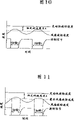
Figure 10 is a view that shows the fan revolution speed control examples, wherein (during ES-FS<A), the fan rotation control signal is temporarily stopped (excision) less than some values (constant speed difference A) when the speed difference between engine rotary speed (ES) and rotational speed (FS).
Figure 11 is a view that shows the fan revolution speed control examples, wherein when motor revolve speed difference between speed (ES) and best fan revolution speed (ETFS) less than some values (constant speed difference A) and fan revolution speed (FS) greater than best fan revolution speed (ES-ETFS<A, and during FS>ETFS), the fan rotation control signal is temporarily stopped (excision).
Figure 12 is a view that shows the fan revolution speed control examples, and wherein (during a>A), the fan rotation control signal is temporarily stopped (excision) greater than some value A as engine revolution acceleration a.
Figure 13 is a view that shows the fan revolution speed control examples, wherein when the acceleration a ' of an accelerator (throttling element) position greater than some value A (a '>A) time, the fan rotation control signal is temporarily stopped (excision).
Figure 14 is a view that shows the fan revolution speed control examples, wherein by the restriction according to the variance ratio of the given best fan revolution speed of variance ratio of best fan revolution speed (ETFS), stablizes the verticity of fan.
Embodiment
In the present invention, Fig. 1 has shown external control system type fan clutch device, seal casinghousing 2 is made of a box body 2-1 and lid 2-2 and is supported by a rotation axis body (live axle) 1, wherein rotates axis body (live axle) 1 and is driven by a drive part (motor) by a bearing 13.The inside of sealing housing is separated into a shoe cream room 5 by a demarcation strip 4 and a moment of torsion transmits chamber 6, and wherein demarcation strip 4 has an oil supply adjustment hole 8.A drive plate 3 is fixedly attached to the terminal of rotation axis body 1 and is positioned at moment of torsion and transmits chamber 6, transmits the gap so that form a moment of torsion between the inner peripheral surface in drive plate 3 and moment of torsion transmission chamber.
Opening and closing are arranged on being used on the box body 2-1 and collect the valve element 9 that is used to supply with oil that circulates passage 7 of oil, are made of a sheet spring 9-1 and an armature 9-2.The bottom part of sheet spring 9-1 is connected on the box body 2-1, thus during the fan rotation, can not bear the oily resistance in the shoe cream room 5 easily, so that the armature 9-2 of valve element 9 is positioned near the rotation axis body (live axle) 1.
An electromagnet 11 is supported by an electromagnet support 12, and this electromagnet support 12 is supported by rotation axis body 1 by the bearing 14 that is positioned at seal casinghousing 2 drive part sides.In addition, the magnetic element of an annular (magnetic material) 10 is assembled in the box body 2-1 and is connected so that relative with the armature 9-2 of above-mentioned valve element.The part of above-mentioned electromagnetism support 12 is assemblied on the magnetic ring 10 brokenly.That is, an operating device that is used for the valve element 9 of oil supply constitutes by the magnetic element 10 that uses annular, effectively the magnetic flux of electromagnet 11 is delivered to the armature 9-2 of valve element.
In the fan clutch device of said structure, when electromagnet 11 is stopped (unmagnetized), by operating sheet spring 9-1 armature 9-2 is separated with magnetic ring 10 and to close oil and supply with adjustment hole 8.Like this, entering oil that moment of torsion transmits chamber 6 supplies with and is stopped.On the contrary, when electromagnet 11 was activated (magnetization), the power of armature 9-2 opposing sheet spring 9-1 attracted to magnetic ring 10 sides.Like this, sheet spring 9-1 oppressed with box body 2-1 side contacts, that opens oily adjustment hole 8, oil supplies to moment of torsion and transmits in the chamber 6.
The control system that is used to carry out the controlling method of said external control type fan clutch device 2 makes an explanation with reference to the accompanying drawings.
At first, the startup of the compressor pressure of the rotational speed of the rotational speed of the cooling fluid temperature of radiator 21, fan 22, the temperature of transmitting oil, car speed, motor 28, air-conditioning, air-conditioning or shutdown signal or the like are imported in the main computing unit 27.A best fan revolution speed (fan revolution speed zone) is judged by this main computing unit.The required valve of change fan rotation opens-and shutdown signal is sent in the relay in the main computing unit 27, perhaps delivers in the relay box 26 of the body that a conduct separates with this main computing unit 27.In this relay or relay box 26, carry out switch motion, power is fed into the electromagnet 11 of fan clutch device 24, and oily supply valve 9 is opened, cuts out.The oil that utilizes this valve to open, close to carry out supplies with that the fan rotation change that causes is perceived, data are fed back to main computing unit 27.In this control system, best fan revolution speed (fan rotation drive area) is determined according to following data once more, and these data comprise the rotational speed of the cooling fluid temperature of radiator 21 for example, the temperature of transmitting oil, car speed, motor etc.In Fig. 2, reference number 23 and 25 is represented a fan turn-sensitive device and a battery respectively.
The controlling method of use of the present invention control system shown in Figure 2 will make an explanation with reference to accompanying drawing 3 and accompanying drawing 4 below.
Best fan revolution speed (TFS) is determined according to following data, the rotational speed of the cooling fluid temperature of the radiator during these data such as the vehicle operating, the temperature of transmitting oil, car speed, motor etc.Calculate the difference E (FS-TFS=E) between best fan revolution speed (TFS) and the actual fan revolution speed FS.Calculate valve according to this difference E to open-shutdown signal and output to relay, open and close the oily supply valve of fan clutch device.Fig. 4 has shown fan Spin Control example.In this example, utilize the valve that calculates according to difference E to open-shutdown signal, the rotational speed of cooling fan is controlled to best rotational speed (TFS) with respect to actual fan revolution speed FS.
For example, (α) the ON/OFF speed of a voltage, (β) electric voltage frequency and (γ) amount of electrical power of power supply can be used as above-mentioned valve and open-shutdown signal.
The on-off speed that Fig. 5 has shown a utilization (α) voltage as valve open-the closing control signal is the example of fan Spin Control to best fan revolution speed (TFS).The on-off frequency that Fig. 6 has shown a utilization (β) voltage as valve open-the closing control signal is the example of fan Spin Control to best fan revolution speed (TFS).The amount of electrical power (W) that Fig. 7 has shown a utilization (γ) power supply as valve open-the closing control signal is the example of fan Spin Control to best fan revolution speed (TFS).As shown in this several Control example, in the present invention, by surveying cooling fluid temperature, transmitting data such as oil temperature, car speed, engine rotary speed and change fan revolution speed such as radiator.Correspondingly, water temperature can be maintained at a certain location, can control the startup and the closing operation of fan clutch device according to engine rotary speed, wherein the cooling fluid temperature of engine rotary speed and radiator is irrelevant, so that prevent the fan noise that related rotation causes.
Except above-mentioned parameter, transmit temperature, intake air temperature, AC compressor pressure, accelerator aperture (accelerator aperture) or the like and also can be used as the parameter that governing factor is set to judge the fan Spin Control.
Fig. 8 has shown a control examples, wherein reduce related rotation (associative rotation) by the operating lag that shortens with respect to the control command of fan revolution speed, Fig. 8 has also shown a kind of by upper limit rotational speed being set at the method for starting the required best fan revolution speed (ETFS) of pusher side to control fan revolution speed.In this controlling method,, upper limit rotational speed line is set on the position at a low slightly startup rotational speed place according to the above-mentioned required best fan revolution speed (ETFS) of pusher side that starts in the normal running.Rotational speed on this line is used as the upper limit of fan revolution speed and controls.
That is, when clutch was arranged on starting state, the moment of torsion that oil excessively flows to clutch transmitted the inside in chamber and stays the there.Therefore, when the signal that reduces fan revolution speed when next is exported constantly, be to postpone one section to collect the required time of above-mentioned oil with respect to the reaction of this signal.In addition, when engine rotary speed under the situation that starts from state of rest at vehicle and quicken immediately when low speed rotation changes to high speed rotating, moment of torsion transmits that excessive oil will become the factor that causes related rotation in the chamber.Therefore, be set in by the upper limit rotational speed with the best fan revolution speed (ETFS) of clutch and be lower than the clutch position place that starts rotational speed slightly, and control this fan revolution speed, making does not have excessive oil to enter moment of torsion to transmit in the chamber.So, to be shortened as much as possible with respect to the operating lag (response delay) of next fan revolution speed control signal constantly, the related rotation with the engine start time during engine revolution changes is shortened.
Fig. 9 has shown an instantiation of fan revolution speed control, and wherein upper limit rotational speed line is provided with according to above-mentioned best fan revolution speed (ETFS).In this example, (ES) changes to 4000rpm from 1000rpm when engine rotary speed, and best fan revolution speed (ETFS) is when being set to 2000rpm consistently, (α) when engine rotary speed (ES) is set to the constant state of 1000rpm, fan revolution speed (FS) is controlled in this upper limit rotational speed line place.Similar with above-mentioned situation, (β) when engine rotary speed (ES) was set to acceleration mode from 1000rpm to 2000rpm, fan revolution speed (FS) was controlled in this upper limit rotational speed line place.(γ) when engine rotary speed (ES) was set to acceleration mode from 2000rpm to 4000rpm, fan revolution speed (FS) was controlled at 2000rpm consistently.
Here, upper limit rotational speed line can be determined engine rotary speed (n) by one as the formula (approximate formula) of variable etc.
Figure 10 and 11 has shown control examples, wherein by temporarily stop the related rotation during (excision) fan revolution speed control signal reduces the engine revolution change according to the speed difference between engine rotary speed, fan revolution speed (actual measured value) and the best fan revolution speed.In control examples shown in Figure 10, (during ES-FS<A), the fan rotation control signal is temporarily stopped (excision) less than a certain value (constant speed difference A) when the speed difference of engine rotary speed (ES) and fan revolution speed (FS).In control examples shown in Figure 11, (when ES-FS<A and FS>ETFS), the fan rotation control signal is temporarily stopped (excision) greater than best fan revolution speed (ETFS) less than a certain value (constant speed difference A) and fan revolution speed (FS) when the speed difference of engine rotary speed (ES) and best fan revolution speed (ETFS).
That is to say, to have the speed difference that utilizes between input rotation and receiving part (fan) oil is collected the into system in moment of torsion transmission chamber as the fan clutch of the target of control system of the present invention.Correspondingly, when above-mentioned speed difference reduced, the gathering speed of oil reduced, and this becomes, and (low speed rotation → high speed rotating) produces the reason of related rotation during the change of engine revolution.Therefore, judge that this speed difference becomes less than a certain value, the fan revolution speed control signal is temporarily stopped (excision).Like this, stop oily overfeeding, reduced related rotation.
Figure 12 and 13 has shown control examples, the related rotation during wherein temporarily stopping (excision) fan revolution speed control signal and reduce engine speed and change by the acceleration according to engine revolution acceleration or an accelerator (throttling element (throttle)) position.In control examples shown in Figure 12, (during a>A), the fan rotation control signal is stopped (excision) greater than a certain particular value when the engine revolution acceleration becomes.In the control examples that Figure 13 shows, when the acceleration a ' of accelerator (throttling element) position become greater than this particular value A (a '>A) time, the fan rotation control signal is stopped (excision).
That is to say, judge that the fan revolution speed control signal is stopped (excision) so that can reduce related rotation in the moment that engine rotary speed is accelerated.
Figure 14 has shown a control examples, wherein by the variance ratio according to best fan revolution speed (ETFS), provides the limit of the variance ratio of an above-mentioned best fan revolution speed, stablizes the verticity of fan.For example, as shown in Figure 14, when best fan revolution speed (ETFS) at time (timing) t when 1000rpm (α) changes to 3000rpm (β), the variance ratio of the every Δ t of this best fan revolution speed (ETFS) becomes 2000rpm/ Δ t.Here, when the limit with every Δ t variance ratio (for example, 500rpm/ Δ t), this best fan revolution speed (ETFS) changes to (γ) from (α).
That is to say that when best fan revolution speed (ETFS) changed at short notice fast, the control of fan Rotable Control System output became unstable (the error variation between best fan revolution speed and actual fan revolution speed has been increased).Correspondingly, convergence (convergent property) variation, fan verticity become unstable.Therefore, the limit of the variance ratio by a given best fan revolution speed (ETFS), the error that can reduce best fan revolution speed (ETFS) changes, thereby stablizes the fan verticity.
Industrial applicibility
The present invention is applied on the fan clutch of cooling automobile radiator, can improve engine performance, joint Economize the energy and improve the cooling performance of the capacitor of air-conditioning (A/C), and can limit because related rotation is led The fan noise that causes reduces the response delay with respect to the control instruction of fan rotation, reduces engine rotation Change during and the related rotation during the engine start, simultaneously can also stablize this fan verticity.
Claims (15)
1. the controlling method of an external control system fan clutch, comprise the external control system fan clutch, the inside of one of them seal casinghousing is separated into a shoe cream room by a demarcation strip and a moment of torsion that is used for inner installation one drive plate transmits the chamber, the sealing housing is made of box body and lid that is connected on this box body that a nonmagnetic substance constitutes, the box body that nonmagnetic substance constitutes is supported by a bearing on a rotation axis body, the terminal fixedly connected drive plate of this rotation axis body; Baffle plate is arranged on the part of inner circumference wall of the lid relative with the outer circle wall part of drive plate during rotation to collect and oil in reserve, oil circulate passage be formed on moment of torsion transmit the chamber and with shoe cream room that baffle plate links to each other between, one has magnetic and opens, closes oil and supply with the valve element of adjustment hole and be arranged on shoe cream room inside, this oil is supplied with adjustment hole and is arranged on the demarcation strip, and this valve element transmits the chamber from moment of torsion and supplies with oil to shoe cream room; The bearing of electromagnet shoe cream room side by being positioned at described seal casinghousing is supported by described rotation axis body, and control oil is supplied with the mechanism that adjustment hole opens and closes and constituted by utilizing the described valve element of operation electriomagnet; This external control type fan clutch is made of a system, this system is used for controlling from driving side to the rotation torque transmission that is driven side by increasing or reduce effective area of contact that oil transmits gap portion at a moment of torsion, and moment of torsion transmits gap portion by driving side be driven side and form; One of them annular magnetic material is arranged between described electromagnet and the valve element, and constitutes by magnetic material is assembled in the seal casinghousing, so that by this magnetic material the magnetic flux of electromagnet is delivered to the valve element; Wherein according to the opening and closing that at least one signal in the signal is controlled described valve element that open or close of the compressor pressure of the temperature of the chilled liquid temperature of radiator, fan revolution speed, transmission oil, car speed, engine rotary speed, air-conditioning, air-conditioning.
2. the controlling method of an external control system fan clutch, comprise the external control system fan clutch, the inside of one of them seal casinghousing is separated into a shoe cream room by a demarcation strip and a moment of torsion that is used for inner installation one drive plate transmits the chamber, the sealing housing is made of box body and a lid that is connected on this box body of a nonmagnetic substance, the box body of nonmagnetic substance is supported by a bearing on a rotation axis body, the terminal fixedly connected drive plate of this rotation axis body; Baffle plate is arranged on the part of inner circumference wall of the lid relative with the outer circle wall part of drive plate during rotation to collect and oil in reserve, oil circulate passage be formed on moment of torsion transmit the chamber and with shoe cream room that baffle plate links to each other between, one has magnetic and opens, closes oil and supply with the valve element of adjustment hole and be arranged on shoe cream room inside, this oil is supplied with adjustment hole and is arranged on the demarcation strip, and this valve element transmits the chamber from moment of torsion and supplies with oil to shoe cream room; The bearing of electromagnet shoe cream room side by being positioned at described seal casinghousing is supported by described rotation axis body, and control oil is supplied with the mechanism that adjustment hole opens and closes and constituted by utilizing the described valve element of operation electriomagnet; This external control type fan clutch is made of a system, this system transmits effective area of contact in the gap portion at a moment of torsion and controls from driving side to the rotation torque transmission that is driven side by increasing or reducing oil, and moment of torsion transmits gap portion by driving side be driven side and form; One of them annular magnetic material is arranged between described electromagnet and the valve element, and constitutes by magnetic material is assembled in the seal casinghousing, so that by this magnetic material the magnetic flux of electromagnet is delivered to the valve element; Wherein to starting the required best fan revolution speed of pusher side that a upper limit rotational speed is set; Temporarily stop a fan rotation speed according to the speed difference between engine rotary speed, fan revolution speed and described best fan revolution speed and become control signal; Acceleration according to an engine revolution acceleration or an acceleration device position temporarily stops this fan revolution speed control signal; Perhaps a variance ratio of this best fan revolution speed is provided a restriction according to the variance ratio of described best fan revolution speed.
3. the controlling method of an external control system fan clutch, comprise the external control system fan clutch, the inside of one of them seal casinghousing is separated into a shoe cream room by a demarcation strip and a moment of torsion that is used for inner installation one drive plate transmits the chamber, the sealing housing is made of box body and a lid that is connected on this box body of a nonmagnetic substance, the box body of nonmagnetic substance is supported by a bearing on a rotation axis body, the terminal fixedly connected drive plate of this rotation axis body; Baffle plate is arranged on the part of inner circumference wall of the lid relative with the outer circle wall part of drive plate during rotation to collect and oil in reserve, oil circulate passage be formed on moment of torsion transmit the chamber and with shoe cream room that baffle plate links to each other between, one has magnetic and opens, closes oil and supply with the valve element of adjustment hole and be arranged on shoe cream room inside, this oil is supplied with adjustment hole and is arranged on the demarcation strip, and this valve element transmits the chamber from moment of torsion and supplies with oil to shoe cream room; The bearing of electromagnet shoe cream room side by being positioned at described seal casinghousing is supported by described rotation axis body, and control oil is supplied with the mechanism that adjustment hole opens and closes and constituted by utilizing the described valve element of operation electriomagnet; This external control type fan clutch is made of a system, this system transmits effective area of contact in the gap portion at a moment of torsion and controls from driving side to the rotation torque transmission that is driven side by increasing or reducing oil, and moment of torsion transmits gap portion by driving side be driven side and form; One of them annular magnetic material is arranged between described electromagnet and the valve element, and constitutes by magnetic material is assembled in the seal casinghousing, so that by this magnetic material the magnetic flux of electromagnet is delivered to the valve element; Wherein to starting the required best fan revolution speed of pusher side that a upper limit rotational speed is set; Temporarily stop a fan revolution speed control signal according to the speed difference between engine rotary speed, fan revolution speed and described best fan revolution speed; Acceleration according to an engine revolution acceleration or a throttling element position temporarily stops this fan revolution speed control signal; Perhaps a variance ratio of this best fan revolution speed is provided a restriction according to the variance ratio of described best fan revolution speed.
4. the controlling method of external control system fan clutch according to claim 1 and 2, it is characterized in that, calculate valve according to the difference between actual fan revolution speed and the best fan revolution speed and open-the closing control signal, fan revolution speed is controlled to best fan revolution speed according to this control signal.
5. the controlling method of external control system fan clutch according to claim 1 and 2 is characterized in that, voltage is used as valve to be opened-the closing control signal, and this control signal controls to best fan revolution speed with fan revolution speed.
6. the controlling method of external control system fan clutch according to claim 1 and 2 is characterized in that, the on-off speed of utilizing voltage as valve open-the closing control signal controls to best fan revolution speed with fan revolution speed.
7. the controlling method of external control system fan clutch according to claim 1 and 2 is characterized in that, the on-off frequency of utilizing voltage as valve open-the closing control signal controls to best fan revolution speed with fan revolution speed.
8. the controlling method of external control system fan clutch according to claim 1 and 2 is characterized in that, the amount of electrical power of utilizing power supply as valve open-the closing control signal controls to best fan revolution speed with fan revolution speed.
9. the controlling method of external control system fan clutch according to claim 1 and 2 is characterized in that, by with respect to starting the required best fan revolution speed capping rotational speed of pusher side to control fan revolution speed.
10. the controlling method of external control system fan clutch according to claim 1 and 2, it is characterized in that, when the speed difference of engine rotary speed and fan revolution speed during, control fan revolution speed by temporarily stopping the fan rotation control signal less than a certain value.
11. the controlling method of external control system fan clutch according to claim 1 and 2, it is characterized in that, when the speed difference of engine rotary speed and best fan revolution speed during greater than best fan revolution speed, is controlled fan revolution speed by temporarily stopping the fan rotation control signal less than a certain value and fan revolution speed.
12. the controlling method of external control system fan clutch according to claim 1 and 2 is characterized in that, when the engine revolution acceleration becomes greater than a certain value, controls fan revolution speed by stopping the fan rotation control signal.
13. the controlling method of external control system fan clutch according to claim 1 and 2 is characterized in that, when the acceleration of acceleration device position becomes greater than a certain value, controls fan revolution speed by stopping the fan rotation control signal.
14. the controlling method of external control system fan clutch according to claim 1 and 2 is characterized in that, when the acceleration of throttling element position becomes greater than a certain value, controls fan revolution speed by stopping the fan rotation control signal.
15. the controlling method of external control system fan clutch according to claim 1 and 2 is characterized in that, provides the limit of the variance ratio of best fan revolution speed by the variance ratio according to best fan revolution speed, controls fan revolution speed.
Applications Claiming Priority (4)
| Application Number | Priority Date | Filing Date | Title |
|---|---|---|---|
| JP2003116072 | 2003-04-21 | ||
| JP116072/2003 | 2003-04-21 | ||
| JP2004113606A JP2004340373A (en) | 2003-04-21 | 2004-04-07 | Control method for externally controlled fan clutch |
| JP113606/2004 | 2004-04-07 |
Publications (2)
| Publication Number | Publication Date |
|---|---|
| CN1550688A CN1550688A (en) | 2004-12-01 |
| CN100365309C true CN100365309C (en) | 2008-01-30 |
Family
ID=33422027
Family Applications (1)
| Application Number | Title | Priority Date | Filing Date |
|---|---|---|---|
| CNB2004100595668A Expired - Fee Related CN100365309C (en) | 2003-04-21 | 2004-04-21 | Control method of external control type fan clutch |
Country Status (5)
| Country | Link |
|---|---|
| US (1) | US8118148B2 (en) |
| JP (1) | JP2004340373A (en) |
| KR (1) | KR100643624B1 (en) |
| CN (1) | CN100365309C (en) |
| DE (1) | DE102004018955B4 (en) |
Cited By (1)
| Publication number | Priority date | Publication date | Assignee | Title |
|---|---|---|---|---|
| CN105570338A (en) * | 2016-02-18 | 2016-05-11 | 太仓钰丰机械工程有限公司 | Mute silicone oil fan clutch |
Families Citing this family (38)
| Publication number | Priority date | Publication date | Assignee | Title |
|---|---|---|---|---|
| JP2004340373A (en) | 2003-04-21 | 2004-12-02 | Usui Kokusai Sangyo Kaisha Ltd | Control method for externally controlled fan clutch |
| JP4753278B2 (en) * | 2004-10-12 | 2011-08-24 | 臼井国際産業株式会社 | Control method of externally controlled fan clutch |
| JP2006162047A (en) * | 2004-12-10 | 2006-06-22 | Usui Kokusai Sangyo Kaisha Ltd | Control method of magnetic fan clutch |
| JP2006177163A (en) * | 2004-12-20 | 2006-07-06 | Usui Kokusai Sangyo Kaisha Ltd | Control method for externally controlled fan clutch |
| CA2615807C (en) * | 2005-07-29 | 2015-11-24 | Horton, Inc. | Viscous clutch having improved flux circuit |
| US7407046B2 (en) * | 2005-09-26 | 2008-08-05 | Usui International Corp. | Adaptive control of externally controlled fan drive |
| DE102006008576A1 (en) * | 2006-02-22 | 2007-08-30 | Behr Gmbh & Co. Kg | Fan drive device for e.g. driving fan impeller of motor vehicle, has valve unit, which is actuated by actuator, where section of actuator is arranged in retaining unit for fastening to motor unit |
| JP5074005B2 (en) * | 2006-10-26 | 2012-11-14 | 臼井国際産業株式会社 | Control method of externally controlled fan coupling device |
| CN101435362B (en) * | 2007-11-16 | 2011-04-13 | 华纳圣龙(宁波)有限公司 | Electric silicon oil clutch water pump |
| KR101013962B1 (en) * | 2007-12-13 | 2011-02-14 | 현대자동차주식회사 | Cooling fan clutch |
| JP5067330B2 (en) * | 2008-09-26 | 2012-11-07 | 日産自動車株式会社 | Cooling fan control device |
| JP5211986B2 (en) * | 2008-09-26 | 2013-06-12 | 日産自動車株式会社 | Cooling fan control device |
| JP5018873B2 (en) * | 2009-12-17 | 2012-09-05 | 日産自動車株式会社 | Diagnostic device for fan coupling device |
| KR101174064B1 (en) * | 2010-02-10 | 2012-08-14 | 주식회사 퓨트로닉 | Coupling apparatus for adjusting a cooling fan rotation |
| JP5522677B2 (en) | 2010-04-28 | 2014-06-18 | 臼井国際産業株式会社 | Highly reactive fluid fan and coupling device |
| KR101241212B1 (en) * | 2010-12-07 | 2013-03-13 | 기아자동차주식회사 | Controlling apparatus for fanclutch's rpm in idle and method thereof |
| PL2530273T3 (en) * | 2011-06-01 | 2020-11-16 | Joseph Vögele AG | Construction machine with automatic ventilator rotation speed regulator |
| KR101417660B1 (en) * | 2013-07-11 | 2014-07-09 | 현대자동차주식회사 | Fan clutch for vehicle |
| JP6391141B2 (en) * | 2014-01-31 | 2018-09-19 | 臼井国際産業株式会社 | Externally controlled fan / clutch device |
| KR101594272B1 (en) | 2014-05-14 | 2016-02-15 | 가부시키가이샤 고마쓰 세이사쿠쇼 | Work vehicle |
| JP6516281B2 (en) * | 2014-05-19 | 2019-05-22 | 臼井国際産業株式会社 | Highly reactive fluid fan and clutch device |
| US9382954B2 (en) * | 2014-05-22 | 2016-07-05 | Gm Global Technology Operations, Llc | Temperature compensated torque limiting valve |
| JP2016031107A (en) * | 2014-07-29 | 2016-03-07 | 臼井国際産業株式会社 | Thermosensitive fluid type fan clutch device |
| US9982728B2 (en) | 2014-10-22 | 2018-05-29 | General Electric Company | System and method for auxiliary clutch failure detection |
| KR101637744B1 (en) | 2014-11-25 | 2016-07-07 | 현대자동차주식회사 | Fan OFF Speed Decrease Method and Variable Case gap type Fan Clutch therefor |
| CN104896461B (en) * | 2015-06-29 | 2016-10-12 | 东方电气集团东方锅炉股份有限公司 | A kind of adjustable steam cooler of built-in part flow arrangement |
| JP6480320B2 (en) * | 2015-12-24 | 2019-03-06 | 株式会社クボタ | Work machine cooling control system and work machine |
| DE112016005993T5 (en) * | 2015-12-24 | 2018-09-13 | Kubota Corporation | Cooling control system for working machine and working machine |
| JP2017227313A (en) * | 2016-06-24 | 2017-12-28 | アイシン精機株式会社 | External control type fluid joint |
| IT201600122636A1 (en) * | 2016-12-02 | 2018-06-02 | Piaggio & C Spa | Engine cooling system |
| CN107120370B (en) | 2017-04-27 | 2019-01-08 | 广州汽车集团股份有限公司 | The guard method of clutch and device in vehicle travel process |
| CN107013304A (en) * | 2017-04-28 | 2017-08-04 | 威隼汽车科技(宁波)有限公司 | A kind of automotive electronics silicon oil filled fan clutch |
| JP7056062B2 (en) | 2017-10-05 | 2022-04-19 | いすゞ自動車株式会社 | Clutch control device |
| KR102487185B1 (en) * | 2017-12-04 | 2023-01-10 | 현대자동차 주식회사 | Cooling fan control method for vehicle |
| US10655688B2 (en) | 2018-02-16 | 2020-05-19 | Standard Motor Products, Inc. | Fan-coupling device with unitary magnetic pole construction |
| CN110985190A (en) * | 2020-03-05 | 2020-04-10 | 盛瑞传动股份有限公司 | Driving disc external transmission type silicone oil clutch for internal combustion engine mechanical water pump |
| CN112065561A (en) * | 2020-09-04 | 2020-12-11 | 北京理工大学 | Engine cooling fan speed adjusting device |
| CN114198423B (en) * | 2021-12-11 | 2023-06-23 | 苏州睿昕汽车配件有限公司 | Oil control mechanism of electric control silicone oil fan clutch |
Citations (4)
| Publication number | Priority date | Publication date | Assignee | Title |
|---|---|---|---|---|
| US4893703A (en) * | 1989-05-22 | 1990-01-16 | General Motors Corporation | Electromagnetic control assembly and method for a viscous fluid fan clutch |
| US5224446A (en) * | 1991-05-16 | 1993-07-06 | Mazda Motor Corporation | Control apparatus for a rotary body for cooling an engine |
| JP2000220662A (en) * | 1999-02-03 | 2000-08-08 | Denso Corp | Rotary machine with electromagnetic clutch |
| US6443283B1 (en) * | 1999-06-02 | 2002-09-03 | Behr Gmbh & Co. | Fluid friction clutch operable with non-magnetic housing or disk parts |
Family Cites Families (30)
| Publication number | Priority date | Publication date | Assignee | Title |
|---|---|---|---|---|
| US3924585A (en) | 1975-01-23 | 1975-12-09 | Eagle Motive Ind Inc | Electromagnetic fan clutch for a water-cooled vehicle engine |
| US4228880A (en) | 1978-09-25 | 1980-10-21 | Eaton Corporation | Pulse control of an electro magnetically actuated viscous fluid coupling |
| DE8233338U1 (en) * | 1982-11-27 | 1983-03-31 | Süddeutsche Kühlerfabrik Julius Fr. Behr GmbH & Co KG, 7000 Stuttgart | Fluid friction clutch |
| DE3243967C2 (en) * | 1982-11-27 | 1986-06-05 | Daimler-Benz Ag, 7000 Stuttgart | Fluid friction clutch |
| DE3706152A1 (en) * | 1987-02-26 | 1988-09-08 | Sueddeutsche Kuehler Behr | METHOD FOR CONTROLLING A VEHICLE AIR CONDITIONER AND VEHICLE AIR CONDITIONER FOR IMPLEMENTING THE METHOD |
| GB2247512B (en) * | 1990-08-30 | 1995-04-05 | Usui Kokusai Sangyo Kk | Fluid clutch |
| JPH04254020A (en) * | 1991-01-31 | 1992-09-09 | Usui Internatl Ind Co Ltd | Hydraulic clutch |
| JP2911623B2 (en) * | 1991-02-07 | 1999-06-23 | 臼井国際産業株式会社 | Liquid clutch |
| JP2911624B2 (en) * | 1991-02-07 | 1999-06-23 | 臼井国際産業株式会社 | Liquid clutch |
| US5636719A (en) | 1994-02-25 | 1997-06-10 | Horton, Inc. | Rotational control apparatus |
| US5484045A (en) | 1994-03-16 | 1996-01-16 | Usui Kokusai Sangyo Kaisha Ltd. | Fluid clutch |
| JP3346644B2 (en) | 1994-03-19 | 2002-11-18 | 臼井国際産業株式会社 | Liquid clutch |
| US5467854A (en) * | 1994-06-07 | 1995-11-21 | Caterpillar Inc. | Method of controlling clutch-to-clutch shifts for a powershift transmission |
| US5584371A (en) | 1995-08-31 | 1996-12-17 | Eaton Corporation | Viscous fan drive system logic |
| JP3786374B2 (en) * | 1995-11-10 | 2006-06-14 | 臼井国際産業株式会社 | Liquid clutch |
| DE19710384A1 (en) | 1997-03-13 | 1998-09-17 | Behr Gmbh & Co | Device for controlling rotational speed for e.g. ventilator for cooling components of vehicle |
| IT1292384B1 (en) | 1997-06-19 | 1999-02-08 | Baruffaldi Spa | MOTORCYCLE TRANSMISSION DEVICE WITH ELECTROMAGNETIC CLUTCH AND EPICYCLOIDAL ROTISM FOR VEHICLE FANS |
| JPH1151219A (en) | 1997-07-30 | 1999-02-26 | Inax Corp | Pressure balancer of hot and cold water |
| US6125981A (en) * | 1998-06-17 | 2000-10-03 | Usui Kokusai Sangyo Kaisha Limited | Temperature sensitive fluid type fan coupling apparatus |
| JP2000199531A (en) * | 1999-01-06 | 2000-07-18 | Usui Internatl Ind Co Ltd | Liquid clutch |
| JP2001027260A (en) | 1999-07-14 | 2001-01-30 | Usui Internatl Ind Co Ltd | Fluidic fan.coupline device of temperature sensitive type |
| JP2001263377A (en) | 2000-03-17 | 2001-09-26 | Unisia Jecs Corp | Electromagnetic and hydraulic clutch |
| JP2002081466A (en) | 2000-06-29 | 2002-03-22 | Usui Internatl Ind Co Ltd | External control type fan coupling device |
| DE10131402B4 (en) * | 2000-06-29 | 2006-04-06 | Usui Kokusai Sangyo K.K. | Externally controlled fan clutch device |
| JP2002013556A (en) | 2000-06-29 | 2002-01-18 | Usui Internatl Ind Co Ltd | External control type fan coupling device |
| KR100348588B1 (en) | 2000-07-07 | 2002-08-14 | 국방과학연구소 | Cooling system for vehicles |
| US6648115B2 (en) | 2001-10-15 | 2003-11-18 | General Motors Corporation | Method for slip power management of a controllable viscous fan drive |
| JP4007489B2 (en) | 2002-02-14 | 2007-11-14 | 臼井国際産業株式会社 | Control method of externally controlled fan coupling device |
| US6749448B2 (en) * | 2002-03-06 | 2004-06-15 | Tyco Electronics Corporation | Transceiver module assembly ejector mechanism |
| JP2004340373A (en) | 2003-04-21 | 2004-12-02 | Usui Kokusai Sangyo Kaisha Ltd | Control method for externally controlled fan clutch |
-
2004
- 2004-04-07 JP JP2004113606A patent/JP2004340373A/en active Pending
- 2004-04-19 US US10/826,988 patent/US8118148B2/en not_active Expired - Fee Related
- 2004-04-20 DE DE102004018955A patent/DE102004018955B4/en not_active Expired - Fee Related
- 2004-04-21 CN CNB2004100595668A patent/CN100365309C/en not_active Expired - Fee Related
- 2004-04-21 KR KR1020040027378A patent/KR100643624B1/en active IP Right Grant
Patent Citations (4)
| Publication number | Priority date | Publication date | Assignee | Title |
|---|---|---|---|---|
| US4893703A (en) * | 1989-05-22 | 1990-01-16 | General Motors Corporation | Electromagnetic control assembly and method for a viscous fluid fan clutch |
| US5224446A (en) * | 1991-05-16 | 1993-07-06 | Mazda Motor Corporation | Control apparatus for a rotary body for cooling an engine |
| JP2000220662A (en) * | 1999-02-03 | 2000-08-08 | Denso Corp | Rotary machine with electromagnetic clutch |
| US6443283B1 (en) * | 1999-06-02 | 2002-09-03 | Behr Gmbh & Co. | Fluid friction clutch operable with non-magnetic housing or disk parts |
Cited By (1)
| Publication number | Priority date | Publication date | Assignee | Title |
|---|---|---|---|---|
| CN105570338A (en) * | 2016-02-18 | 2016-05-11 | 太仓钰丰机械工程有限公司 | Mute silicone oil fan clutch |
Also Published As
| Publication number | Publication date |
|---|---|
| DE102004018955B4 (en) | 2012-12-06 |
| KR100643624B1 (en) | 2006-11-10 |
| US8118148B2 (en) | 2012-02-21 |
| US20040223851A1 (en) | 2004-11-11 |
| DE102004018955A1 (en) | 2005-03-24 |
| JP2004340373A (en) | 2004-12-02 |
| KR20040091582A (en) | 2004-10-28 |
| CN1550688A (en) | 2004-12-01 |
Similar Documents
| Publication | Publication Date | Title |
|---|---|---|
| CN100365309C (en) | Control method of external control type fan clutch | |
| JP4007489B2 (en) | Control method of externally controlled fan coupling device | |
| KR100730975B1 (en) | Control method for external type clutch | |
| US7488271B2 (en) | Control method of magnet type fan clutch | |
| US7128690B2 (en) | Method for controlling magnet type fan clutch | |
| JP2003239741A5 (en) | ||
| WO2009046037A2 (en) | Electronically controlled fluid coupling device with fluid scavenge control | |
| WO2008008287A1 (en) | Viscous fan drive systems having fill and scavenge control | |
| JP3786374B2 (en) | Liquid clutch | |
| JP5067330B2 (en) | Cooling fan control device | |
| CN101529111B (en) | External control type fan coupling device control method | |
| EP0832771A2 (en) | Heating apparatus for vehicle, having heat-generating unit | |
| JP4753282B2 (en) | Control method of externally controlled fan clutch | |
| EP0834413B1 (en) | Heating apparatus for vehicle, having heat-generating unit | |
| JPH10100648A (en) | Heating device for vehicle | |
| JP5211986B2 (en) | Cooling fan control device | |
| JPH01247728A (en) | Control device for idling revolution number of internal combustion engine | |
| JPH109290A (en) | Fluid control device and fluid coupling | |
| JPH11227450A (en) | Heating system for vehicle |
Legal Events
| Date | Code | Title | Description |
|---|---|---|---|
| C06 | Publication | ||
| PB01 | Publication | ||
| C10 | Entry into substantive examination | ||
| SE01 | Entry into force of request for substantive examination | ||
| C14 | Grant of patent or utility model | ||
| GR01 | Patent grant | ||
| CF01 | Termination of patent right due to non-payment of annual fee |
Granted publication date: 20080130 Termination date: 20210421 |
|
| CF01 | Termination of patent right due to non-payment of annual fee |