CN100361784C - Method and apparatus for heating polishing pad - Google Patents
Method and apparatus for heating polishing pad Download PDFInfo
- Publication number
- CN100361784C CN100361784C CNB038123959A CN03812395A CN100361784C CN 100361784 C CN100361784 C CN 100361784C CN B038123959 A CNB038123959 A CN B038123959A CN 03812395 A CN03812395 A CN 03812395A CN 100361784 C CN100361784 C CN 100361784C
- Authority
- CN
- China
- Prior art keywords
- polishing pad
- temperature
- fluid
- platform
- manifold
- Prior art date
- Legal status (The legal status is an assumption and is not a legal conclusion. Google has not performed a legal analysis and makes no representation as to the accuracy of the status listed.)
- Expired - Fee Related
Links
Images


Classifications
-
- B—PERFORMING OPERATIONS; TRANSPORTING
- B24—GRINDING; POLISHING
- B24B—MACHINES, DEVICES, OR PROCESSES FOR GRINDING OR POLISHING; DRESSING OR CONDITIONING OF ABRADING SURFACES; FEEDING OF GRINDING, POLISHING, OR LAPPING AGENTS
- B24B37/00—Lapping machines or devices; Accessories
- B24B37/11—Lapping tools
- B24B37/12—Lapping plates for working plane surfaces
-
- B—PERFORMING OPERATIONS; TRANSPORTING
- B24—GRINDING; POLISHING
- B24B—MACHINES, DEVICES, OR PROCESSES FOR GRINDING OR POLISHING; DRESSING OR CONDITIONING OF ABRADING SURFACES; FEEDING OF GRINDING, POLISHING, OR LAPPING AGENTS
- B24B21/00—Machines or devices using grinding or polishing belts; Accessories therefor
- B24B21/04—Machines or devices using grinding or polishing belts; Accessories therefor for grinding plane surfaces
- B24B21/10—Machines or devices using grinding or polishing belts; Accessories therefor for grinding plane surfaces involving a rigid member, e.g. pressure bar, table, pressing or supporting the belt over substantially its whole span
-
- B—PERFORMING OPERATIONS; TRANSPORTING
- B24—GRINDING; POLISHING
- B24B—MACHINES, DEVICES, OR PROCESSES FOR GRINDING OR POLISHING; DRESSING OR CONDITIONING OF ABRADING SURFACES; FEEDING OF GRINDING, POLISHING, OR LAPPING AGENTS
- B24B49/00—Measuring or gauging equipment for controlling the feed movement of the grinding tool or work; Arrangements of indicating or measuring equipment, e.g. for indicating the start of the grinding operation
- B24B49/14—Measuring or gauging equipment for controlling the feed movement of the grinding tool or work; Arrangements of indicating or measuring equipment, e.g. for indicating the start of the grinding operation taking regard of the temperature during grinding
Landscapes
- Engineering & Computer Science (AREA)
- Mechanical Engineering (AREA)
- Finish Polishing, Edge Sharpening, And Grinding By Specific Grinding Devices (AREA)
- Mechanical Treatment Of Semiconductor (AREA)
Abstract
A temperature controlling system for use in a chemical mechanical planarization (CMP) system having a linear polishing belt (102), a carrier (108) capable of applying a substrate (104) over a preparation location over the linear polishing belt is provided. The temperature controlling system includes a platen (110) having a plurality of zones. The temperature controlling system further includes a temperature sensor (160) configured determine a temperature of the linear polishing belt at a location that is after the preparation location. The system also includes a controller (150) for adjusting a flow of temperature conditioned fluid to selected zones of the plurality of zones of the platen in response to output received from the temperature sensor.
Description
Technical field
The invention relates to a kind of chemical-mechanical planarization device, more particularly, is about the temperature by control one polishing pad, improves the inhomogeneity method and apparatus in the chemical mechanical planarization applications.
Prior art
In the manufacturing of semiconductor devices, need to implement the operation of chemical-mechanical planarization (CMP, Chemical Mechanical Planarizaiton).Usually, IC-components is the form of sandwich construction.In the substrate aspect, form transistor device with diffusion zone.In ensuing each aspect, interconnect metallization lines is patterned and is electrically connected to this transistor device and determines required functional device.Well-known, the conductor layer of patterning is by dielectric material and other conductor layer mutually insulated, for example silica.When more metal layers and associated dielectric layers formation, to the also increase thereupon of demand of this dielectric material planarization.If no planarization, the manufacturing of metal layer thereafter will become more difficult, because due to the variation of surface topography.In other application, the pattern of metallized thread is formed in the dielectric material, implements metal CMP then and operates and remove unnecessary material.
As mentioned above, the CMP system is commonly used to polished wafer.The CMP system comprises the system unit that is used for handling with the polished wafer surface usually.For instance, such parts can be a rail mounted polishing pad or linear strip polishing pad.Polishing pad itself usually by polyurethane (polyurethane) or polyurethane in conjunction with other material (as stainless steel band) formation.In operation, during this belt pad was in and moves, a grout material was smeared and is interspersed among on the surface of this belt pad then.Move with required speed in case have the belt pad of slurry on this its, wafer just is reduced on the surface of this belt pad.Mode according to this, the wafer surface that need carry out planarization can become smooth haply, just as sand paper is used for wood.Next wafer cleans in a wafer purging system.
Figure 1A is the linear planarization device 10 that a typical case is used for the CMP system.This linear planarization device 10 grinds off the material on semiconductor wafer 16 surfaces.The material that is removed may or be formed at one layer or more on the wafer 16 for the substrate material of wafer 16.This layer comprises one or more any kind of usually and forms or be present in material in the CMP process, for instance, and as dielectric material, silicon nitride, metal (as aluminium or copper), metal alloy, semi-conducting material or the like.Usually CMP can be used to the one layer or more on the polished wafer 16, with the superficial layer of planarization wafer 16.
One wafer carrier 18 is fixed wafer 16.Wafer 16 is usually by mechanical retaining ring and/or vacuum and remain on the appropriate location.Wafer carrier places wafer on the sand belt 12, contacts in order to do the polished surface of the surface that makes wafer 16 with sand belt 12.
Figure 1B illustrates the side view of linear planarization device 10.Discuss as Figure 1A, wafer carrier 18 is fixed on appropriate location on the sand belt 12 with wafer 16, applies pressure to sand belt simultaneously.Sand belt 12 is generally the made continuous band of a polymer, and for instance, as the IC 1000 of Rodel company manufacturing, it is laminated on the supporting layer.Sand belt 12 rotates around roller 20, and roller 20 orders about sand belt and moves 22 with respect to wafer 16 with rectilinear direction.In an example, a fluid support platform 23 supporting wafers 16 are placed the sand belt part under the zone.This platform 24 can be used to apply the lower surface of fluid to supporting layer then.Therefore the fluid that is applied forms fluid supporting, and it produces the polish pressure that applies facing to wafer 16 surfaces in sand belt 12 belows.Unfortunately because by the polishing speed that fluid bearing produced usually can't be good control, so the polish pressure that fluid bearing applied is inhomogeneous.Especially, the temperature of sand belt 12 can change to some extent when polishing process carries out.When wafer polishing, temperature is lower at the beginning usually for sand belt 12, then becomes higher.When wafer polishing was carried out, the temperature of sand belt can raise because of the friction between sand belt 12, slurry and the wafer 16.This is very serious problem, because when the temperature of sand belt 12 raise, the temperature of the slurry that uses also can rise in the polishing process, thereby has increased the polishing speed of wafer 16.In addition, when air is used as fluid bearing, cold especially usually by the air that platform 24 is discharged.Its generation former be because when air is discharged by the steam vent in the platform 24, gas expansion thereby turn cold.Therefore, since the cold air that frictional heat and platform 24 are discharged, the temperature of very difficult usually control sand belt.So, because the control polishing dynamics that the design of the polishing system of prior art can't be suitable, therefore inhomogeneous polishing and inconsistent wafer polishing meeting cause wafer yield to descend and increase the wafer cost.
In view of the foregoing, thus we need a kind ofly can to improve the control of polishing pad temperature and to reduce the device that the inconsistent platform of polishing speed overcomes prior art problems by having one.
Summary of the invention
Extensively in fact, embodiments of the invention can satisfy these demands, by a polishing pad heating system is provided, adopt the different temperatures air can be provided at the inhomogeneity control of wafer polishing in the CMP process by zones of different in platform.
In one embodiment, provide the temperature control system of a kind of CMP of being used for system, this CMP system comprises that a linear planarization band, can be applied to substrate the locational carrier of this linear planarization band top preparation.This temperature control system comprises a platform, and this platform has a plurality of zones.This temperature control system also comprises a temperature sensor, is used for measuring the temperature of this linear planarization band position after this preparation position.This temperature control system also comprises a controller, is used for regulating the adjusted fluid of temperature flowing to the selection area in these a plurality of zones of platform in response to the output signal that is received by this temperature sensor.
In another embodiment, provide the temperature control system of a kind of CMP of being used for system, this CMP system comprises the carrier that a linear planarization band, can be applied to substrate this preparation position, linear planarization band top.This temperature control system comprises a platform, and this platform has a plurality of zones.This temperature control system also comprises a temperature sensor, is used for measuring the temperature of this linear planarization band position after this preparation position.This temperature control system also comprises a heater, and this heater is positioned at before this preparation position, and faces the surface of this linear planarization band.This temperature control system more comprises a controller, is used in response to the output of being adjusted this heater by the output signal of this temperature sensor reception.
A kind of method that heats polishing pad in the CMP process is provided.Whether this method comprises the temperature of measuring this polishing pad and equates with a set point temperatures haply.This method determines also whether the temperature of this polishing pad is unequal with this set point temperatures haply.If the temperature of this polishing pad is haply with this set point temperatures when unequal, at least one temperature and the pressure that add hot fluid that this method adjustment is exported by at least one pressure span of a platform.This set-up procedure makes this polishing pad temperature equate haply with this set point temperatures.
In another embodiment, a kind of equipment that heats polishing pad in the CMP process is disclosed.This equipment comprises a platform, and it is disposed under this polishing pad.This platform has a landing slab, and this landing slab has at least one exportable pressure span that adds hot fluid to this polishing pad below part.This equipment also comprises manifold in, and manifold is connected to this platform by at least one fluid output in this.Should can this be added at least one pressure span that hot fluid is delivered to this platform by this at least one fluid output by interior manifold.This equipment also comprises an outer manifold, and it is connected to manifold in this by at least one manifold throughput.This outer manifold can add this hot fluid and be delivered to manifold in this.This equipment also comprises a heater, and this heater is connected to this outer manifold by at least one heater throughput.This heater can be heated to fluid one of them of a plurality of design temperatures, and can carry this to add hot fluid to being somebody's turn to do outer manifold.This equipment also comprises a controller, and this controller is connected to a manifold and a polishing pad temperature sensor in this.This controller can be monitored the temperature of polishing pad, and can adjust this and add hot fluid by the conveying of manifold in this at least one pressure span, so that the temperature of this polishing pad equates with this design temperature.
Because will have control temperature controlling fluid pressure applications in the advantage of the zones of different of platform, so embodiments of the invention have improved the uniformity of planarization speed greatly.Other enforcement aspect of the present invention and advantage illustrate the detailed description of the principle of the invention via following conjunction with figs., will be easier to understand.
Description of drawings
The present invention and its additional advantage will be by being easier to understand with reference to above-mentioned detailed description and conjunction with figs., wherein:
Figure 1A is the linear planarization device that a typical case is used for the CMP system;
Figure 1B is the side view of a linear planarization device;
Fig. 2 A is the side view according to the CMP system of one embodiment of the invention;
Fig. 2 B is according to one embodiment of the invention, has the side view of the CMP system of a polishing pad heater;
Fig. 3 shows the annexation between the interior manifold according to one embodiment of the invention, outer manifold and the heater;
Fig. 4 A is the feature top view according to the platform of one embodiment of the invention;
Fig. 4 B is according to one embodiment of the invention, the side view of the diameter tangent plane of platform shown in Fig. 4 A;
Fig. 4 C shows according to one embodiment of the invention to have the platform structure of concentric temperature zones;
Fig. 4 D shows according to one embodiment of the invention to have the platform structure in horizontal pressure force zone;
Fig. 4 E is the schematic diagram according to the polishing pad heat treated of one embodiment of the invention;
Fig. 5 is the network chart according to embodiments of the invention, and it shows that the networking that how to see through different component connects and controls temperature;
Fig. 6 A is the calcspar according to the PID of one embodiment of the invention control, and it is used for controlling the temperature (n is a controlled pressure span number) of the regional n of platform;
Fig. 6 B is the calcspar according to the PID control of one embodiment of the invention, and it is controlled water temperature by the delivery outlet of prewetting with the wet delivery outlet in back and carries;
Fig. 7 is according to one embodiment of the invention, the flow chart of the method for heating polishing pad.
The specific embodiment
The present invention discloses a kind of CMP system that can control polishing uniformity in the CMP process, and it is by adopting different fluid temperature (F.T.)s to export the temperature of controlling polishing pad by the zones of different to a platform in the CMP process.In ensuing explanation, propose many clear and definite details thorough understanding of the present invention is provided.Yet those skilled in the art still can implement the present invention under part or all these situation about offering some clarification on of shortage.In other example, well known process steps does not elaborate, with the present invention that avoids confusion.
Usually, embodiments of the invention provide a CMP system, and it has the special ability of controlling wafer polishing speed by the temperature of control polishing pad in the CMP process.Need to understand this CMP system and can be used in any suitable polishing pad structure, for instance, support sand belt etc. as linear planarization band, stainless steel.The fluid temperature (F.T.) of this CMP system control input platform is so that zones of different can be exported the fluid of identical or different temperature to polishing pad in the platform.The adjusted fluid output of temperature produces fluid supporting, and it makes polishing pad can be set in specified temp.When the temperature of polishing pad was subjected to suitable control, polishing speed also was controlled, and made wafer polishing more even and more efficient.Specifically, control module can be controlled the zones of different that the fluid that is heated inputs to platform, and this is the feedback of coming by by a polishing pad temperature sensor, so forms the temperature that an intelligent backfeed loop is controlled polishing pad.Therefore, caused polish pressure difference of different polishing pad temperature and inconsistent can a mode of highly being regulated being controlled.
The platform that is utilized in the disclosed herein CMP system can contain the pressure span of any number in wafer area or outside the wafer area.Each pressure span comprises a plurality of fluid bore, and it can be used to export fluid at differing temperatures (with respect to another side on polished wafer surface) to the back side of polishing pad, so can compensate the shortcoming on the polishing pad dynamics.Need to understand embodiments of the invention and can be used for polishing the wafer of any size, for instance, as 200mm wafer or 300mm wafer.
Fluid utilized herein can be any type of gas or liquid.Therefore, the CMP system of the explanation polishing speed that can utilize gas that temperature is controlled or liquid to control wafer next.In addition, fluid at differing temperatures can be applied on the specified pressure zone of platform by different pressures.So design can make that the control of wafer polishing speed is extremely flexible.
Fig. 2 A is the side view according to the CMP system 100 of one embodiment of the invention.In this embodiment, a carrier head 108 is used to wafer 104 be fixed and kept in position in operation.Polishing pad 102 is preferably formed as a continuous loop around rotation roller 112.Polishing pad 102 moves towards direction 106 with the speed of 400 feet of per minutes usually, yet needing to understand this speed can change according to specific CMP operation.When polishing pad 102 detoured, carrier 108 then reduced the upper surface of wafer 104 to polishing pad 102.
In polishing process, a platform 110 is supporting polishing pad 102.Platform 110 can utilize the supporting of any suitable form, for example liquid supporting or gas supporting.The fluid pressure that is come by manifold 114 in is imported by platform 110, can provide up pressure to a plurality of delivery outlets of polishing pad 102, with the pressure distribution of control polishing pad by independent control.The fluid pressure permeate fluid throughput 132 that is sent to platform 110 by an interior manifold 114 provides.Fluid output 132 can comprise one or more path that fluid can be transported to platform 110 by interior manifold 114.The different land regions of fluid output 132 supplies, so the fluid output of the zones of different of platform 110 can be controlled.Therefore, for any number can controlled platform 110 independent fluid output zone, just exist the path of equal number to be supplied to each these zone by interior manifold 114.Need to understand in platform 110, the fluid output zone of any proper number all follows the corresponding path of any proper number to be supplied to this zone.
In one embodiment, the set point temperatures of polishing pad is lower than Fahrenheit 125 degree.Need to understand this set point temperatures and can be any proper temperature, decide according to required polishing speed.Polishing speed faster if desired, then set point temperatures is higher.If need slower polishing speed, then set point temperatures is lower.
Fig. 2 B is according to one embodiment of the invention, have the CMP system 100 of a polishing pad heater ' side view.In this example, this system 100 ' comprise can be used to heat the polishing pad heater 130 of polishing pad 102.In one embodiment, this polishing pad heater 130 is disposed at polishing pad 102 tops and is positioned at the back edge side of platform 110.Polishing pad heater 130 can utilize any suitable mode to heat polishing pad 102.In one embodiment, heater 130 is a pharoid, and it is one can heat the heating lamp of polishing pad 102.Control 150 ' can receive from the input of temperature sensor 160 determines the heat that heater 130 is exported, and reaches or keep the set point temperatures of polishing pad 102.In one embodiment, polishing pad heater 130 can be in the temperature temperature of polishing pad of raising of working under up to Fahrenheit 250 degree.Therefore, the temperature of polishing pad 102 can by utilize the hot polishing pads 102 of heating lamp 130 simultaneously the temperature of polishing pads 102 be subjected to temperature sensor and controller 150 ' monitored.
Fig. 3 shows the annexation Figure 180 between interior manifold 114, outer manifold 120 and the heater 118 according to one embodiment of the invention.In one embodiment, four fluid at differing temperatures are utilized.Dry air, deionization water or other fluid as cleaning all can be used in the equipment described herein.In one embodiment, air can heat by heater 118, and is delivered to platform 110 by interior manifold 114 with outer manifold 120.In another embodiment, the combination of air and water can be heated by heater 118, and carries with outer manifold 120 by interior manifold 114.In another embodiment, water can heat by heater 118, and is delivered to platform 110 through interior manifold 114 with outer manifold 120.Different fluid temperature that need to understand heater 118 exportable any proper numbers is to outer manifold 120, thus the different fluid temperature of supplying any suitable respective number interior manifold 114 extremely.
In one embodiment, interior manifold 114 has an electron pressure (EP, electronicpressure) adjuster is controlled fluid and flow to platform 110.So, interior manifold 114 fluid that can be controlled to the fluid pressure of platform 110 and supply any proper temperature is to the fluid output zone of any suitable platform 110.In one embodiment, heater can be respectively by pipeline 124a, 124b, 124c, with the 124d output temperature be Fahrenheit 50,60,70, with the fluids of 80 degree.Preferably utilize the temperature that is lower than Fahrenheit 125 degree.In one embodiment, pipeline 124a, 124b, 124c, determined heater throughput 124 with 124d.The then fluid can be respectively imported by pipeline 124a, 124b, 124c, with 124d of outer manifold 120 interior manifold 114 extremely by pipeline 122a, 122b, 122c, with 122d output.In one embodiment, pipeline 122a, 122b, 122c, determined manifold throughput 122 with 122d.Then, in one embodiment, interior manifold 114 is by the management of controller 150, control fluid temperature (F.T.) and pressure via pipeline 132a, 132b, 132c, 132d, 132e, and 132f export six different fluid circulation portion zones of platform 110 to, and in one embodiment, these pipelines have determined fluid output 132.Need to understand the heater that heater 118 can be any appropriate format, it can heat volume required fluid to and require temperature.In one embodiment, heater can be 40 kilowatts of heaters, but supply temperature is up to the fluid of Fahrenheit 125 degree.
Fig. 4 A is the feature top view according to the platform 110 of one embodiment of the invention.Though shown exemplary platen configuration has specific pressure sub-zones, any platform with fluid pressure zones of proper number and structure all can be used in the system 100 shown in Fig. 2 A.
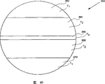
In one embodiment, surrounding fluid throughput zone 204a comprises different annular sub-zones, and annular sub-zones comprises the concentric air pressure zones of different sizes.Need to understand the sub-region that peripheral region 204a and middle section 204b can have any number, for instance, as 2,3,4,5,6,7,8,9,10 etc.Also need understand the sub-region that peripheral region 204a and middle section 204b can have Any shape, for instance, as circular sub-region, semicircle sub-region etc.In one embodiment, peripheral region 204a has five sub-regions, comprises annular sub-zones 204a-1,204a-2,204a-3,204a-4 and 204a-5, and middle section 204b only comprises a zone and do not have the sub-region.Each sub-region all can be controlled respectively, and so the flow velocity of air by different sub-regions just changed and optimize CMP and operate.By the flow velocity of indivedual control air, can comprise on wafer that the different-diameter place of exterior domain in the periphery produces the variation of pressure by different sub-regions.Therefore, a plurality of sub-regions among the regional around 204a and middle section 204b can control temperature and the pressure fine setting that puts on polishing pad 102 zoness of different.This pressure and variation of temperature can be used to change the polishing speed of wafer different piece, because as everyone knows, betide polished amount on the part of wafer and be the function of the pressure on the corresponding part that puts on polishing pad, and be the function of polishing pad 102 temperature in the polishing.Therefore, more or less sub-region can be used according to polishing profile demand.Need to understand, do not have, one or more air pressure sub-zones can have the circumference bigger than polished wafer.
Fig. 4 B is according to one embodiment of the invention, the side view of the diameter tangent plane of platform 110 shown in Fig. 4 A.This platform comprise a landing slab 202, fixed head 228, with a platen cover 222.In this example, annular recess 206a, the 206b of exportable air, 206c, 206d, 206e, be configured in the landing slab 202 with 206f.Need to understand, any number of exportable fluid and the groove part of structure can be used, and decide according to the structure and the number of desired fluid pressure zones.For instance, in another embodiment, groove can be semicircle rather than ring-type, and perhaps in another embodiment, ring-type and semicircular groove part are used.Annular recess 206a, 206b, 206c, 206d, be designed to receive by at least one with 206e and be formed at fluid input port wherein and the fluid that comes, and accommodating fluid is to annular sub-zones 204a-1,204a-2,204a-3,204a-4 and 204a-5, so the zone of five different fluid pressure results from the peripheral region 204a respectively.Annular recess 206f is designed to the middle body of accommodating fluid to platform, and so fluid pressure can result from the middle section 204b.Landing slab 202 optionally comprises an end point detection hole 224, and it can be used for the operation of CMP terminal detecting.In addition, the air/water wet line 238 of prewetting after line 236 and the air/water is defined as forming circle and passes landing slab inside.The air/water line 236 of prewetting can have the delivery outlet 232 of prewetting to landing slab 202 surfaces.Wet line 238 can have the surface of the wet delivery outlet 230 in back to landing slab 202 after the air/water.By injecting water by line 236 and line 238, landing slab 202 can be wetted earlier before CMP operation beginning.
Therefore, in operation, air injects by input hole 234, and arrives fluid input port to annular recess 206a, 206b, 206c, 206d, 206e, 206f and 206g feeding by bedplate 228.Then fluid pressure orders about fluid again and flows out to regional 204a-1,204a-2,204a-3,204a-4,204a-5 and 204b.
Fig. 4 C shows according to one embodiment of the invention to have the platform structure 340 of concentric temperature zones.In this example, platform structure 340 comprises 342,344,346,348 and one central pressure span 350, a plurality of concentric pressure span.Each pressure span 342,344,346,348, with 350 all exportable fluid at differing temperatures or the fluid of uniform temp or the fluid of any appropriate combination temperature.
Fig. 4 D shows according to one embodiment of the invention to have the platform structure 360 in horizontal pressure force zone.In this example, platform structure 360 comprises horizontal temperature zones 362,364,366,368 and 370.The fluid of all exportable fluid at differing temperatures of each horizontal temperature zones or uniform temp or the fluid of any appropriate combination temperature.
Fig. 4 E is the schematic diagram 380 according to the polishing pad heat treated of one embodiment of the invention.In this example, the carrier head 108 of fixing wafer 104 is pressed on the polishing pad 102 that moves towards direction 106.In this example, shown platform 110 applies the below of hot-air to polishing pad 102 by a plurality of pressure spans.In addition, the shown delivery outlet 232 of prewetting applies the below of hot water to polishing pad 102 with the wet delivery outlet 230 in back.Simultaneously, HTS 160 is surveyed the temperature of polishing pad 102 and is passed through a backfeed loop, controller 150 (shown in Fig. 2 A) monitoring and adjust by what platform 110 was applied and add hot fluid, and also adjust the hot water of being carried by prewet delivery outlet 232 and the wet delivery outlet 230 in back.In addition, heater 130 is configurable on polishing pad 102 and heating polishing pad to a design temperature.Heater 130 can being used by selectivity shown in Fig. 2 B, perhaps utilizes hot-air to pass platform in addition and heat polishing pad 102.
Fig. 5 is the network chart 400 according to one embodiment of the invention, and how it show that networking by different component connects and control temperature.This control chart shows that one is connected to the touch-screen 402 of a timer 404, and timer is connected to a Internet switch 406 again.The Internet switch 406 is connected to troop a controller 408 and a temperature controller 410.In one embodiment, touch-screen 402 allows the user be set fluid zones pressure, fluid temperature (F.T.), hot water output and current fluid mass of monitoring and hot water temperature.The transmission and the reception of data between timer 404 control touch-screens 402 and the Internet switch 406.The data that is transmitted on the Internet switch 406 guiding networkings is to desired position.Node in the cluster control unit 408 management networkings, and assist the processing that resource is distributed in the networking.Temperature controller 150 can receive and require setting air regional temperature and hot water set point.Temperature controller 150 also can be implemented proportional-integral-differential (PID, Proportional, Integral, Derivative) control (next PID control will be done with reference to figure 6A and 6B and be described in more detail) to all air sections and hot water temperature.Temperature controller 410 also can be done the synchronous driving of current region temperature and hot water for each requirement.Temperature controller 410 can be the controller of any appropriate format, and its design is used for receiving above-mentioned input signal, carries out pid control signal (next will do with reference to figure 6A and be described in more detail) and produces output controls a plurality of controllable devices (as interior manifold).In one embodiment, temperature controller 410 can be a programmable logic controller (PLC) (PLC, Programmable LogicController), as the resulting PLC of supplier of the PLC that can be fit to by Siemens or other.Perhaps, temperature controller 410 can be any type of general computer system, as PC.
Fig. 6 A is the calcspar 500 according to the PID of one embodiment of the invention control, and it is used for controlling the temperature (n is a controlled pressure span number) of the regional n of platform 110.Need to understand PID control described herein can be used to control with management platform 110 on the temperature of any pressure span.In one embodiment, zone 1,2,3,4,5, with 6 can correspond respectively to annular sub-zones 204a-1,204a-2,204a-3,204a-4,204a-5, with middle section 204b.
Though described PID control is the temperature about the regional n of control platform 110, same principle also can be applicable to control any other controlled variable, as the flow of control fluid at a specified temp.Required set point can be set as the temperature of a required pressure span n.This air section n can be any fluid mass, and it is arranged in the platform 110 that fluid output can independently be controlled.Therefore, calcspar 500 can be used to be controlled at the temperature of fluid output in any fluid output zone.One required set point imports 502 as temperature required being applied in a special air zone.Ratio, integration, differential parameter K
p, K
i, K
dBy extracting in the signal that is sent to input 502.Each PID parameter is added into corresponding PID calculating 504a, 504b, 504c produces a control signal 510.For instance, this control signal output can be the air themperature control signal in zone 1.During control signal 510 then is applied to a control output heater power source and handles (temperature control signals as zone 1 is applied to first area temperature controlling input).Handle and also to receive and the signal that utilizes for controlled specific region from electron pressure (EP) adjuster.One feedback signal 512 feeds back to input 502 an error control/feedback is provided.If being applied to the set point of input 502 is the required air temperature of air section 1, then feedback signal 512 can be an air themperature that is detected from air section 1, for example from temperature sensor.Mode according to this, the All Ranges of platform 110 can an intelligent mode be controlled and manage, and so the temperature of polishing pad can equate with set point temperatures basically.
Fig. 6 B is the calcspar 560 according to the PID control of one embodiment of the invention, and it is carried with back wet delivery outlet control water temperature by the delivery outlet of prewetting.PID control described in the calcspar 560 is about control the temperature and the output of hot water by the wet delivery outlet in delivery outlet and back of prewetting.Required set point is set as the temperature required of hot water.Hot water can be transported to platform 110, and is delivered to the upper surface of platform by the wet delivery outlet in delivery outlet and back of prewetting.One required set point, water temperature is applied to input 562 as required.Ratio, integration, differential parameter K
p, K
i, K
dBy extracting in the signal that is sent to input 562.Each PID parameter is added into corresponding PID calculating 564a, 564b, 564c produces a control signal 566.For instance, this control signal output can be a pre-wet heated water control signal.During control signal 566 is then delivered to a control output heating power supply and is handled (being applied to the input of polishing pad temperature controlling) as the pre-wet heated water control signal.One feedback signal 568 feeds back to input 562 an error control/feedback is provided.In one embodiment, be that then feedback signal 568 can be a water temperature that is detected from the delivery outlet of prewetting, for example from a temperature sensor from the required water temperature of the delivery outlet of prewetting if be applied to the set point of input 562.
Fig. 7 is according to one embodiment of the invention, the flow chart 600 of the method for heating polishing pad 102.The method is by operation 602 beginnings of decision polishing pad temperature.In this operation, controller receives the signal of the indication polishing pad temperature of being come by a heat sensor.After the operation 602, this method proceeds to determines whether polishing pad is in the design temperature operation 604 of (or being called set point temperatures).In operation 604, controller is polishing pad temperature and set point temperatures relatively.If polishing pad is not in design temperature, then this method moves to operation 606, this operation is by the temperature and the pressure that change by the different pressures zone fluid of export of platform, and by change by prewet delivery outlet and after the wet temperature of water that delivery outlet is exported adjust the polishing pad temperature to design temperature.
Therefore, by the fluid temperature (F.T.) that intelligent management and control platform are exported, the polishing pad temperature just can be controlled to the wafer polishing speed that provides best.In addition, by control polishing pad temperature, polishing speed can decide according to required polishing speed.Therefore, the CMP system of explanation can reach the optimal chip polishing operation herein.
Though the present invention understands in order to provide clearly, has done detailed explanation with reference to embodiment, it should not be considered to it is restrictive.Those skilled in the art are with reference to narration of the present invention, when doing various modifications to disclosed embodiment easily.Therefore anyly do not break away from category of the present invention, and, all should be contained in the accompanying Claim scope its modification of carrying out or change.
Claims (7)
- One kind in Chemical Mechanical Polishing (CMP) the heating polishing pad equipment, comprise:One platform is disposed under this polishing pad, and this platform has a landing slab, and it has at least one exportable pressure span that adds hot fluid to this polishing pad below part;Manifold in one is connected to this platform by at least one fluid output, and manifold can add at least one pressure span that hot fluid is delivered to this platform with this by at least one fluid output in this;One outer manifold is connected to manifold in this by at least one manifold throughput, and this outer manifold can add this hot fluid and be delivered to manifold in this;One heater is connected to this outer manifold by at least one heater throughput, and this heater can be heated to fluid one of them of a plurality of design temperatures, and can carry this to add hot fluid to being somebody's turn to do outer manifold; AndOne controller, be connected to a manifold and a polishing pad temperature sensor in this, this controller can be monitored the temperature of polishing pad, and can adjust this add hot fluid in this manifold to the conveying of this at least one pressure span, so that the temperature of this polishing pad equates with this design temperature.
- 2. the equipment of heating polishing pad according to claim 1, wherein this at least one pressure span comprises six pressure spans.
- 3. the equipment of heating polishing pad according to claim 2, wherein this at least one pressure span comprises a middle section and a peripheral region.
- 4. the equipment of heating polishing pad according to claim 3, wherein this peripheral region comprises at least 5 circular pressure zones.
- 5. the equipment of heating polishing pad according to claim 1, wherein this platform comprises prewet delivery outlet and the wet delivery outlet in back.
- 6. the equipment of heating polishing pad according to claim 5, wherein at least one the temperature that adds hot fluid from this wet delivery outlet in delivery outlet and this back of prewetting can be changed.
- 7. the equipment of heating polishing pad according to claim 1, wherein this heater can add hot-air to Fahrenheit 125 degree.
Applications Claiming Priority (2)
| Application Number | Priority Date | Filing Date | Title |
|---|---|---|---|
| US10/112,628 US6896586B2 (en) | 2002-03-29 | 2002-03-29 | Method and apparatus for heating polishing pad |
| US10/112,628 | 2002-03-29 |
Publications (2)
| Publication Number | Publication Date |
|---|---|
| CN1665642A CN1665642A (en) | 2005-09-07 |
| CN100361784C true CN100361784C (en) | 2008-01-16 |
Family
ID=28453390
Family Applications (1)
| Application Number | Title | Priority Date | Filing Date |
|---|---|---|---|
| CNB038123959A Expired - Fee Related CN100361784C (en) | 2002-03-29 | 2003-03-28 | Method and apparatus for heating polishing pad |
Country Status (7)
| Country | Link |
|---|---|
| US (1) | US6896586B2 (en) |
| EP (1) | EP1497076A4 (en) |
| JP (1) | JP2005526383A (en) |
| CN (1) | CN100361784C (en) |
| AU (1) | AU2003220560A1 (en) |
| TW (1) | TWI258399B (en) |
| WO (1) | WO2003082521A1 (en) |
Families Citing this family (28)
| Publication number | Priority date | Publication date | Assignee | Title |
|---|---|---|---|---|
| WO2007045267A1 (en) * | 2005-10-19 | 2007-04-26 | Freescale Semiconductor, Inc. | A system and method for cleaning a conditioning device |
| US7883393B2 (en) * | 2005-11-08 | 2011-02-08 | Freescale Semiconductor, Inc. | System and method for removing particles from a polishing pad |
| JP4787063B2 (en) * | 2005-12-09 | 2011-10-05 | 株式会社荏原製作所 | Polishing apparatus and polishing method |
| US20070227901A1 (en) * | 2006-03-30 | 2007-10-04 | Applied Materials, Inc. | Temperature control for ECMP process |
| JP4902433B2 (en) * | 2007-06-13 | 2012-03-21 | 株式会社荏原製作所 | Polishing surface heating and cooling device for polishing equipment |
| DE102007041209B4 (en) * | 2007-08-31 | 2017-11-23 | Globalfoundries Dresden Module One Limited Liability Company & Co. Kg | Polishing head using zone control |
| US20090287340A1 (en) * | 2008-05-15 | 2009-11-19 | Confluense Llc | In-line effluent analysis method and apparatus for CMP process control |
| KR101698615B1 (en) | 2008-12-10 | 2017-01-20 | 램 리써치 코포레이션 | Platen and adapter assemblies for facilitating silicon electrode polishing |
| JP5547472B2 (en) * | 2009-12-28 | 2014-07-16 | 株式会社荏原製作所 | Substrate polishing apparatus, substrate polishing method, and polishing pad surface temperature control apparatus for substrate polishing apparatus |
| CN102528651B (en) * | 2010-12-21 | 2014-10-22 | 中国科学院微电子研究所 | Chemical mechanical polishing equipment and preheating method for same |
| JP2012148376A (en) * | 2011-01-20 | 2012-08-09 | Ebara Corp | Polishing method and polishing apparatus |
| JP5628067B2 (en) * | 2011-02-25 | 2014-11-19 | 株式会社荏原製作所 | Polishing apparatus provided with temperature adjustment mechanism of polishing pad |
| CN102794698B (en) * | 2012-08-16 | 2015-10-21 | 中国科学院西安光学精密机械研究所 | The grinding and polishing device of radiant temperature field accelerated corrosion |
| CN102785145B (en) * | 2012-08-16 | 2015-07-29 | 中国科学院西安光学精密机械研究所 | Based on the gasbag-type grinding and polishing device of control corrosion rate |
| US9550270B2 (en) * | 2013-07-31 | 2017-01-24 | Taiwan Semiconductor Manufacturing Company Limited | Temperature modification for chemical mechanical polishing |
| JP6161999B2 (en) * | 2013-08-27 | 2017-07-12 | 株式会社荏原製作所 | Polishing method and polishing apparatus |
| CN103612182A (en) * | 2013-11-27 | 2014-03-05 | 苏州道众机械制造有限公司 | Flat belt grinder |
| US10454752B2 (en) | 2015-11-02 | 2019-10-22 | Servicenow, Inc. | System and method for processing alerts indicative of conditions of a computing infrastructure |
| KR102331074B1 (en) * | 2017-04-11 | 2021-11-25 | 주식회사 케이씨텍 | Substrate processing apparatus |
| JP6923342B2 (en) * | 2017-04-11 | 2021-08-18 | 株式会社荏原製作所 | Polishing equipment and polishing method |
| DE202017105160U1 (en) * | 2017-05-18 | 2018-08-22 | Steinemann Technology Ag | Belt grinding device for monitoring an abrasive belt |
| CN108296341A (en) * | 2018-04-13 | 2018-07-20 | 宁波得晴电器科技有限公司 | A kind of bolster moulding process |
| JP7287987B2 (en) | 2018-06-27 | 2023-06-06 | アプライド マテリアルズ インコーポレイテッド | Temperature control for chemical mechanical polishing |
| US11897079B2 (en) | 2019-08-13 | 2024-02-13 | Applied Materials, Inc. | Low-temperature metal CMP for minimizing dishing and corrosion, and improving pad asperity |
| WO2022006008A1 (en) * | 2020-06-29 | 2022-01-06 | Applied Materials, Inc. | Control of steam generation for chemical mechanical polishing |
| US11919123B2 (en) * | 2020-06-30 | 2024-03-05 | Applied Materials, Inc. | Apparatus and method for CMP temperature control |
| CN112677019B (en) * | 2020-12-23 | 2022-08-23 | 北京半导体专用设备研究所(中国电子科技集团公司第四十五研究所) | Pressure detection device and polishing equipment |
| CN115673953B (en) * | 2022-06-20 | 2023-10-03 | 南通鑫耐隔热材料有限公司 | Fiberboard processing is with polishing grinding device |
Citations (6)
| Publication number | Priority date | Publication date | Assignee | Title |
|---|---|---|---|---|
| US5873769A (en) * | 1997-05-30 | 1999-02-23 | Industrial Technology Research Institute | Temperature compensated chemical mechanical polishing to achieve uniform removal rates |
| CN1230014A (en) * | 1998-03-06 | 1999-09-29 | 西门子公司 | Improved method and apparatus for chemical mechanical planarization (CMP) of semiconductor wafer |
| US6000997A (en) * | 1998-07-10 | 1999-12-14 | Aplex, Inc. | Temperature regulation in a CMP process |
| CN1274949A (en) * | 1999-05-19 | 2000-11-29 | 因芬尼昂技术北美公司 | System for transfering polishing liquid when semiconductor wafer is chemimechanical polished |
| US6224461B1 (en) * | 1999-03-29 | 2001-05-01 | Lam Research Corporation | Method and apparatus for stabilizing the process temperature during chemical mechanical polishing |
| US6352470B2 (en) * | 1999-08-31 | 2002-03-05 | Micron Technology, Inc. | Method and apparatus for supporting and cleaning a polishing pad for chemical-mechanical planarization of microelectronic substrates |
Family Cites Families (4)
| Publication number | Priority date | Publication date | Assignee | Title |
|---|---|---|---|---|
| DE3128880A1 (en) * | 1981-07-22 | 1983-02-10 | Fa. Peter Wolters, 2370 Rendsburg | MACHINE FOR LAPPING OR POLISHING |
| US5957750A (en) * | 1997-12-18 | 1999-09-28 | Micron Technology, Inc. | Method and apparatus for controlling a temperature of a polishing pad used in planarizing substrates |
| JP3693483B2 (en) * | 1998-01-30 | 2005-09-07 | 株式会社荏原製作所 | Polishing equipment |
| US6568991B2 (en) * | 2001-08-28 | 2003-05-27 | Speedfam-Ipec Corporation | Method and apparatus for sensing a wafer in a carrier |
-
2002
- 2002-03-29 US US10/112,628 patent/US6896586B2/en not_active Expired - Fee Related
-
2003
- 2003-03-27 TW TW092107031A patent/TWI258399B/en not_active IP Right Cessation
- 2003-03-28 AU AU2003220560A patent/AU2003220560A1/en not_active Abandoned
- 2003-03-28 JP JP2003580034A patent/JP2005526383A/en active Pending
- 2003-03-28 WO PCT/US2003/009465 patent/WO2003082521A1/en active Application Filing
- 2003-03-28 CN CNB038123959A patent/CN100361784C/en not_active Expired - Fee Related
- 2003-03-28 EP EP03716874A patent/EP1497076A4/en not_active Withdrawn
Patent Citations (6)
| Publication number | Priority date | Publication date | Assignee | Title |
|---|---|---|---|---|
| US5873769A (en) * | 1997-05-30 | 1999-02-23 | Industrial Technology Research Institute | Temperature compensated chemical mechanical polishing to achieve uniform removal rates |
| CN1230014A (en) * | 1998-03-06 | 1999-09-29 | 西门子公司 | Improved method and apparatus for chemical mechanical planarization (CMP) of semiconductor wafer |
| US6000997A (en) * | 1998-07-10 | 1999-12-14 | Aplex, Inc. | Temperature regulation in a CMP process |
| US6224461B1 (en) * | 1999-03-29 | 2001-05-01 | Lam Research Corporation | Method and apparatus for stabilizing the process temperature during chemical mechanical polishing |
| CN1274949A (en) * | 1999-05-19 | 2000-11-29 | 因芬尼昂技术北美公司 | System for transfering polishing liquid when semiconductor wafer is chemimechanical polished |
| US6352470B2 (en) * | 1999-08-31 | 2002-03-05 | Micron Technology, Inc. | Method and apparatus for supporting and cleaning a polishing pad for chemical-mechanical planarization of microelectronic substrates |
Also Published As
| Publication number | Publication date |
|---|---|
| TW200402351A (en) | 2004-02-16 |
| CN1665642A (en) | 2005-09-07 |
| TWI258399B (en) | 2006-07-21 |
| US6896586B2 (en) | 2005-05-24 |
| EP1497076A1 (en) | 2005-01-19 |
| EP1497076A4 (en) | 2008-07-16 |
| JP2005526383A (en) | 2005-09-02 |
| WO2003082521A1 (en) | 2003-10-09 |
| AU2003220560A1 (en) | 2003-10-13 |
| US20030186623A1 (en) | 2003-10-02 |
Similar Documents
| Publication | Publication Date | Title |
|---|---|---|
| CN100361784C (en) | Method and apparatus for heating polishing pad | |
| KR100993029B1 (en) | Apparatus and methods for controlling wafer temperature in chemical mechanical polishing | |
| US6544111B1 (en) | Polishing apparatus and polishing table therefor | |
| US6000997A (en) | Temperature regulation in a CMP process | |
| TW483804B (en) | Method and apparatus for stabilizing the temperature during chemical mechanical polishing | |
| US20090036032A1 (en) | Temperature control for ecmp process | |
| US7467990B2 (en) | Back pressure control system for CMP and wafer polishing | |
| US6267659B1 (en) | Stacked polish pad | |
| US11919123B2 (en) | Apparatus and method for CMP temperature control | |
| WO2002078904A1 (en) | Support for a polishing belt | |
| US20020009953A1 (en) | Control of CMP removal rate uniformity by selective heating of pad area | |
| US7153188B1 (en) | Temperature control in a chemical mechanical polishing system | |
| US6769970B1 (en) | Fluid venting platen for optimizing wafer polishing | |
| US20190287866A1 (en) | Chemical mechanical polishing apparatus containing hydraulic multi-chamber bladder and method of using thereof | |
| US6729945B2 (en) | Apparatus for controlling leading edge and trailing edge polishing | |
| CN219599095U (en) | Chemical mechanical polishing equipment | |
| JP3680343B2 (en) | Chemical mechanical polishing apparatus and semiconductor device manufacturing method | |
| US20170352573A1 (en) | Substrate processing apparatus | |
| US20240157504A1 (en) | Apparatus and method for cmp temperature control | |
| JP2002083791A (en) | Polishing apparatus |
Legal Events
| Date | Code | Title | Description |
|---|---|---|---|
| C06 | Publication | ||
| PB01 | Publication | ||
| C10 | Entry into substantive examination | ||
| SE01 | Entry into force of request for substantive examination | ||
| C14 | Grant of patent or utility model | ||
| GR01 | Patent grant | ||
| C19 | Lapse of patent right due to non-payment of the annual fee | ||
| CF01 | Termination of patent right due to non-payment of annual fee |