CN100359137C - First stage protective cover structure of turbomachine and reinforced maintenance method - Google Patents
First stage protective cover structure of turbomachine and reinforced maintenance method Download PDFInfo
- Publication number
- CN100359137C CN100359137C CNB2004100282019A CN200410028201A CN100359137C CN 100359137 C CN100359137 C CN 100359137C CN B2004100282019 A CNB2004100282019 A CN B2004100282019A CN 200410028201 A CN200410028201 A CN 200410028201A CN 100359137 C CN100359137 C CN 100359137C
- Authority
- CN
- China
- Prior art keywords
- guard shield
- shield
- uncinus
- outer shield
- trailing edge
- Prior art date
- Legal status (The legal status is an assumption and is not a legal conclusion. Google has not performed a legal analysis and makes no representation as to the accuracy of the status listed.)
- Expired - Lifetime
Links
- 238000000034 method Methods 0.000 title claims description 14
- 238000012423 maintenance Methods 0.000 title description 2
- 230000001681 protective effect Effects 0.000 title 1
- 230000011218 segmentation Effects 0.000 claims description 26
- 238000011144 upstream manufacturing Methods 0.000 claims description 7
- 239000004744 fabric Substances 0.000 claims description 5
- 238000007789 sealing Methods 0.000 claims description 5
- 238000001816 cooling Methods 0.000 claims description 4
- 239000002826 coolant Substances 0.000 claims 2
- 238000013461 design Methods 0.000 description 4
- 230000002787 reinforcement Effects 0.000 description 3
- 238000010276 construction Methods 0.000 description 2
- 238000007796 conventional method Methods 0.000 description 2
- 238000003754 machining Methods 0.000 description 2
- NMFHJNAPXOMSRX-PUPDPRJKSA-N [(1r)-3-(3,4-dimethoxyphenyl)-1-[3-(2-morpholin-4-ylethoxy)phenyl]propyl] (2s)-1-[(2s)-2-(3,4,5-trimethoxyphenyl)butanoyl]piperidine-2-carboxylate Chemical compound C([C@@H](OC(=O)[C@@H]1CCCCN1C(=O)[C@@H](CC)C=1C=C(OC)C(OC)=C(OC)C=1)C=1C=C(OCCN2CCOCC2)C=CC=1)CC1=CC=C(OC)C(OC)=C1 NMFHJNAPXOMSRX-PUPDPRJKSA-N 0.000 description 1
- 230000008878 coupling Effects 0.000 description 1
- 238000010168 coupling process Methods 0.000 description 1
- 238000005859 coupling reaction Methods 0.000 description 1
- 230000007547 defect Effects 0.000 description 1
- 230000001419 dependent effect Effects 0.000 description 1
- 238000009434 installation Methods 0.000 description 1
- 239000002184 metal Substances 0.000 description 1
- 238000012986 modification Methods 0.000 description 1
- 230000004048 modification Effects 0.000 description 1
- 230000002265 prevention Effects 0.000 description 1
- 238000012545 processing Methods 0.000 description 1
Images


Classifications
-
- F—MECHANICAL ENGINEERING; LIGHTING; HEATING; WEAPONS; BLASTING
- F01—MACHINES OR ENGINES IN GENERAL; ENGINE PLANTS IN GENERAL; STEAM ENGINES
- F01D—NON-POSITIVE DISPLACEMENT MACHINES OR ENGINES, e.g. STEAM TURBINES
- F01D5/00—Blades; Blade-carrying members; Heating, heat-insulating, cooling or antivibration means on the blades or the members
-
- F—MECHANICAL ENGINEERING; LIGHTING; HEATING; WEAPONS; BLASTING
- F01—MACHINES OR ENGINES IN GENERAL; ENGINE PLANTS IN GENERAL; STEAM ENGINES
- F01D—NON-POSITIVE DISPLACEMENT MACHINES OR ENGINES, e.g. STEAM TURBINES
- F01D11/00—Preventing or minimising internal leakage of working-fluid, e.g. between stages
- F01D11/08—Preventing or minimising internal leakage of working-fluid, e.g. between stages for sealing space between rotor blade tips and stator
-
- F—MECHANICAL ENGINEERING; LIGHTING; HEATING; WEAPONS; BLASTING
- F01—MACHINES OR ENGINES IN GENERAL; ENGINE PLANTS IN GENERAL; STEAM ENGINES
- F01D—NON-POSITIVE DISPLACEMENT MACHINES OR ENGINES, e.g. STEAM TURBINES
- F01D25/00—Component parts, details, or accessories, not provided for in, or of interest apart from, other groups
- F01D25/24—Casings; Casing parts, e.g. diaphragms, casing fastenings
- F01D25/246—Fastening of diaphragms or stator-rings
-
- F—MECHANICAL ENGINEERING; LIGHTING; HEATING; WEAPONS; BLASTING
- F05—INDEXING SCHEMES RELATING TO ENGINES OR PUMPS IN VARIOUS SUBCLASSES OF CLASSES F01-F04
- F05D—INDEXING SCHEME FOR ASPECTS RELATING TO NON-POSITIVE-DISPLACEMENT MACHINES OR ENGINES, GAS-TURBINES OR JET-PROPULSION PLANTS
- F05D2240/00—Components
- F05D2240/10—Stators
- F05D2240/11—Shroud seal segments
-
- F—MECHANICAL ENGINEERING; LIGHTING; HEATING; WEAPONS; BLASTING
- F05—INDEXING SCHEMES RELATING TO ENGINES OR PUMPS IN VARIOUS SUBCLASSES OF CLASSES F01-F04
- F05D—INDEXING SCHEME FOR ASPECTS RELATING TO NON-POSITIVE-DISPLACEMENT MACHINES OR ENGINES, GAS-TURBINES OR JET-PROPULSION PLANTS
- F05D2260/00—Function
- F05D2260/20—Heat transfer, e.g. cooling
- F05D2260/201—Heat transfer, e.g. cooling by impingement of a fluid
-
- Y—GENERAL TAGGING OF NEW TECHNOLOGICAL DEVELOPMENTS; GENERAL TAGGING OF CROSS-SECTIONAL TECHNOLOGIES SPANNING OVER SEVERAL SECTIONS OF THE IPC; TECHNICAL SUBJECTS COVERED BY FORMER USPC CROSS-REFERENCE ART COLLECTIONS [XRACs] AND DIGESTS
- Y10—TECHNICAL SUBJECTS COVERED BY FORMER USPC
- Y10T—TECHNICAL SUBJECTS COVERED BY FORMER US CLASSIFICATION
- Y10T29/00—Metal working
- Y10T29/49—Method of mechanical manufacture
- Y10T29/49316—Impeller making
- Y10T29/49318—Repairing or disassembling
-
- Y—GENERAL TAGGING OF NEW TECHNOLOGICAL DEVELOPMENTS; GENERAL TAGGING OF CROSS-SECTIONAL TECHNOLOGIES SPANNING OVER SEVERAL SECTIONS OF THE IPC; TECHNICAL SUBJECTS COVERED BY FORMER USPC CROSS-REFERENCE ART COLLECTIONS [XRACs] AND DIGESTS
- Y10—TECHNICAL SUBJECTS COVERED BY FORMER USPC
- Y10T—TECHNICAL SUBJECTS COVERED BY FORMER US CLASSIFICATION
- Y10T29/00—Metal working
- Y10T29/49—Method of mechanical manufacture
- Y10T29/49316—Impeller making
- Y10T29/4932—Turbomachine making
- Y10T29/49323—Assembling fluid flow directing devices, e.g., stators, diaphragms, nozzles
Landscapes
- Engineering & Computer Science (AREA)
- Mechanical Engineering (AREA)
- General Engineering & Computer Science (AREA)
- Turbine Rotor Nozzle Sealing (AREA)
- Structures Of Non-Positive Displacement Pumps (AREA)
Abstract
A stator shroud segment is provided that includes an outer shroud 116 having a leading edge groove 126 and a trailing edge groove 128, both grooves of the outer shroud opening in a first, axial direction; and a plurality of inner shrouds 118 each having a leading edge hook 110 and a trailing edge hook 112. The hook of the inner shroud projects in a second, axial direction, opposite the first axial direction, and leading and trailing hooks of each of the inner shrouds are respectively engaged with the leading and trailing edge grooves of the outer shroud so as to axially and radially lock the inner shroud to the outer shroud. This assembly simplifies access to the inner shroud and simplifies the removal of the inner shroud without increasing complexity.
Description
Background technique
In industry gas turbine, the guard shield segmentation is fixed on the turbine cylinder uncinus in the mode around turbine rotor axis annular array, to form radially outward and the contiguous ring shield that constitutes blade (bucket) end of a turbine rotor part.The guard shield inwall forms the part of gas passageway.Usually, the guard shield segmentation is made up of interior and outer shield, in this and outer shield be provided be close to its air inlet and exhaust limit, with the hook and the groove of interior and the complementation that outer shield is joined to one another.Outer shield is fixed with turbine casing or casing hook again.In typical structure, each guard shield segmentation has an outer shield and two or three interior guard shields.
In the past, interior shroud structure adopts two kinds of modes commonly used, i.e. an opposite hook scheme and a C collar scheme.Opposite hook scheme is more traditional method and comprises by opposite outstanding hook on the air inlet of outer shield restriction and the trailing edge.This scheme safeguards that the main disadvantage in aspect is: interior guard shield can not move vertically, can only along the circumferential direction skid off housing.Being limited in of this scheme: before the guard shield of being concerned about touching, need elder generation that the cover assembly of some cooperations is removed.
Therefore, for traditional opposite hook scheme, in order to dismantle specific interior guard shield, have to pull down all relevant guard shields, its method is to unload the anti-of them to ship and resell on another market, along the circumferential direction one by one they are skidded off then, the guard shield of being concerned about up to touching.For the 6C motor that 66 elements are arranged, before the interior guard shield of being concerned about touching, need pull down more than 5 extra outer shields and 15 the interior guard shields.
The conventional method of above-mentioned second kind of C collar scheme provides the method that the guard shield reinforcement is safeguarded opposite hook in a kind of can the contact vertically.Traditional C collar scheme as shown in Figure 1.
As can be seen from the figure, identical with traditional opposite hook method, this scheme also comprises oppositely outstanding air inlet and trailing edge uncinus 10,12.But trailing edge uncinus 12 limits them with independent C collar 14 when oppositely being limited by outer shield 16 again.By removing C collar 14, just can interior guard shield 18 be removed, thereby only the guard shield of being concerned about 18 be removed along axial direction (among the figure shown in the arrow A), just can strengthen housekeeping operation.Yet, should be noted that, at least one adjacent interior guard shield in about one to three guard shield on each side (not shown), also essential the maintenance, seal along circumferential moving to remove fabric.
There are two major defects in above-mentioned C collar scheme.The firstth, the complexity that C collar member of adding and device increase.These elements and device comprise C collar itself, resist and ship and resell on another market and require to provide axial and radial location face, the bearing surface of C collar and the machining set-up of fixed pin holes.Second shortcoming of C collar scheme be, in order to safeguard near C collar pin, must along the circumferential direction move be concerned about that the second level nozzle of the turbine stage in the zone, this operation require to remove that nozzle is anti-ships and resell on another market.
Summary of the invention
Therefore, wish further to strengthen safeguarding, for example improve maintaining method and reduce complexity.
The present invention recommends a kind of with traditional reverse hook scheme to compare with C collar scheme, guard shield in the first order of turbine stage is improved to inverted leading edge uncinus, thereby can moves axially the guard shield of being concerned about, and need not to move other guard shield.The scheme of the inverted uncinus that provides according to the embodiment of the invention can not increase the complexity of C collar scheme, and contact method is simplified.
Therefore, the concrete stator guard shield segmentation of the present invention comprises: an outer shield, this outer shield has a leading edge and a trailing edge, and the footpath is inwardly with directly to the outside, said outer shield comprises a leading edge uncinus and a trailing edge uncinus, and two said uncinuses of said outer shield are axially outstanding along first; Guard shield in a plurality of, guard shield all has a leading edge and a trailing edge in each, and the footpath is inwardly with directly to the outside, guard shield comprises a leading edge uncinus and a trailing edge uncinus in said, two said uncinuses of guard shield are along second axially outstanding in said, and this is second axially axially just in time opposite with said first; The said air inlet and the uncinus of giving vent to anger of guard shield all engaged with the said air inlet of said outer shield and the uncinus of giving vent to anger respectively in each was said, and said joint is locked to guard shield in said on the said outer shield vertically and radially; With anti-shipping and reselling on another market, it passes the hole that forms in the leading edge of described outer shield, stretch into the corresponding jack that forms in the described leading edge uncinus of guard shield in described, along the circumferential direction guard shield in described is locked on the described outer shield, described hole is defined by described outer shield, and described pin is to be easy to move from described outer shield when radially being locked on the described outer shield with the described interior guard shield of box lunch.
The present invention also provides a kind of stator guard shield of multistage gas turbine, it is characterized in that, comprise: one has the guard shield segmentation on a surface, this surface portion ground forms the hot-gas channel that runs through a turbine stage, and should the surface integral arrangement in the end of the blade of a said turbine stage that constitutes a turbine rotor part, said guard shield segmentation has a leading edge and a trailing edge; Said guard shield segmentation comprises an outer shield and at least one interior guard shield that is connected with outer shield; Said outer shield has by groove adjacent and that form along each said leading edge and trailing edge, and said groove is opening in the same way vertically; Guard shield has the short and small protuberance that short and small protuberance that a leading edge axially stretches out and a trailing edge axially stretch out in said, this protuberance respectively with the said engage grooves of said outer shield, said joint is locked to guard shield in said on the said outer shield vertically and radially; With anti-shipping and reselling on another market, should anti-ship and resell on another market and pass the hole that forms in the said outer shield, stretch into the corresponding jack that in said, forms in the guard shield, along the circumferential direction guard shield in said is locked on the said outer shield, described hole is defined by described outer shield, and described pin is to be easy to move from described outer shield when radially being locked on the described outer shield with the described interior guard shield of box lunch.
The present invention also is specially a kind of method of separating and pull down guard shield in first from outer shield, wherein, interior guard shield has leading edge uncinus and trailing edge uncinus, outer shield has and the said air inlet of the said first interior guard shield and leading edge groove and the trailing edge groove that the trailing edge uncinus is bonded with each other, the said air inlet of guard shield and trailing edge uncinus are outstanding along the same axis in said first, and said method comprises: pull down or move vertically the counterpart on the guard shield upstream side in said first; Pull down engages with guard shield and said outer shield in said first first in guard shield resist and ship and resell on another market; Take out anti-shipping and reselling on another market from the contiguous interior guard shield of periphery, and the contiguous interior guard shield of periphery that slides, till the sealing of the fabric between them is thrown off; The guard shield in said first that slides is vertically pulled down said air inlet and trailing edge uncinus from the said air inlet and the trailing edge uncinus of said outer shield; And move said first guard shield vertically, throw off and pull down guard shield in said first.
Description of drawings
By conscientiously studying below in conjunction with the detailed description of accompanying drawing to the preferred exemplary embodiments of the present invention, can understand and pay attention to these and other objects of the present invention and advantage more up hill and dale, in:
Fig. 1 be schematic guard shield segmentation along circumferential end elevation, express that guard shield keeps scheme in traditional C collar;
Fig. 2 is the schematic along circumferential end elevation of the concrete guard shield segmentation of the present invention;
Fig. 3 is that the guard shield segmentation has two interior guard shield segmentations, do not show the perspective view of the inner radial structure of outer shield among Fig. 2;
Fig. 4 is the perspective view of above-mentioned assembly shown in Figure 3; And
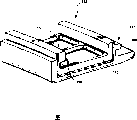
Fig. 5 is the perspective view according to the interior guard shield of the embodiment of the invention.
Embodiment
As mentioned above, Fig. 1 schematically shows a kind of traditional C collar scheme.As shown in the figure, interior guard shield 18 comprises in one guard shield uncinus 10 and interior guard shield trailing edge or downstream side uncinus 12 in guard shield leading edge or the upstream edge, and they engage with the air inlet and the trailing edge uncinus 20,22 of corresponding outer shield 16 respectively.Interior guard shield trailing edge uncinus 12 usefulness one independent C collar 14 is fixed with the trailing edge uncinus 22 of outer shield 16, rather than is kept by the outer shield structure.In order to pull down interior guard shield, must remove C collar 14, radially (arrow R) motion of guard shield 18 in allowing, perhaps more properly say it is to rotate around leading edge uncinus 10, trailing edge up to interior guard shield is thrown off outer shield 16, then, interior guard shield 18 (arrow A) vertically moves, up to throwing off outer shield 16 fully.As mentioned above, except additional C collar member and device have increased the complexity, the designing requirement of C collar removes that nozzle is anti-ships and resell on another market, allow institute is concerned about regional in the second level nozzle of turbine stage along the circumferential direction mobile so that can safeguard near C collar pin (not shown).
With reference to Fig. 2-5, express a guard shield segmentation (representing with 100 usually) among the figure, it is made up of outer shield 116 and a plurality of interior guard shield 118.Guard shield in two or three is set usually.Guard shield segmentation 100 shown in the figure comprises three interior guard shields 118, only expresses one of them for clear among the figure.Described in detail as follows, interior guard shield has respectively the uncinus 110 and 112 near its air inlet and trailing edge, along the circumferential direction slidably engages with the groove 126 and 128 that the uncinus 120,122 of outer shield 116 forms when being used in the end assembling.In the embodiment shown, adopted will impact in the conventional method cooling plate 124 be installed in structure between the guard shield, so that the inner wall surface of guard shield segmentation 100 is impacted cooling.
In the illustrated embodiment, outer shield 116 has radially an outer dovetail 130, it engages with the wedge slot 132 that is formed by the air inlet and the uncinus 134,136 of giving vent to anger, and wherein the air inlet and the uncinus of giving vent to anger form the guard shield segmentation is fixed to the fixed turbine engine housing on the casing or the part of casing.Be appreciated that the conduct replaceable scheme of description architecture, outwards wedge slot of a footpath can be set, on the outer shield to receive the dovetail of the correspondingly-shaped that constitutes a turbine case part.Significant be that the annular array of guard shield segmentation 100 forms around the rotor of gas turbine with around the top of rotor upper blade, thereby forms an outer wall or border for the hot gas that flows through turbo machine hot gas path.In Fig. 2, complete sum can reference express in the secondary nozzle structure 176 of first order jet nozzle structure 172, turbine stage blade 174 and turbine stage of guard shield seal groove 170, turbine stage.
As mentioned above, one embodiment of the present of invention provide a kind of reverse hook shroud structure, and guard shield 118 engaged and tightens up with outer shield 1 16 in this structure made, and safeguarded and the assembling ability thereby improve.Referring to Fig. 2, this figure is a detailed end elevation along the circumferential direction of expressing the guard shield segmentation 100 of coupling element, above-mentioned as can be seen outer shield 116 engages with the air inlet and the casing uncinus 134,136 of giving vent to anger, and the outer shield that is provided is anti-ships and resell on another market and 138 stretches into corresponding groove 140 (Fig. 4), with along the circumferential direction with outer shield 116 and casing 142 lockings.In the illustrated embodiment, outer shield seal groove 144 is expressed as air measuring hole 146 and striking plate 124.The anti-pin hole 148 that changes of guard shield in also being provided with on the leading edge of outer shield, this hole and corresponding aperture 150 are point-blank and guard shield is anti-in receiving ships and resell on another market 152.
Compare with conventional construction above-described with shown in Figure 1, the leading edge uncinus 120 of outer shield 116 is reverse, the short and small protuberance 154 that comprises upstream vertically, stretches out away from trailing edge.The short and small protuberance 156 that the trailing edge uncinus 122 of outer shield 116 also comprises one upstream vertically, stretch out towards trailing edge, the short and small protuberance 154 of itself and air inlet edge uncinus 120 is equidirectional.Therefore, two of outer shield 116 grooves 126 and 128 upstream direction opening vertically all.
The uncinus 110 of interior guard shield 118 and 112 engages with air inlet and trailing edge uncinus 120,122, particularly engages with the groove 126,128 of outer shield 116.More precisely, in the illustrated embodiment, the short and small protuberance 158 that the leading edge uncinus 110 of interior guard shield comprises one downstream vertically, stretch out to trailing edge, thereby axially and radially engage with the uncinus 120 of outer shield 116, and then axially and radially lock outer and inner guard shield.Should be noted that turbine stage first order retaining ring (being turbine stage first order nozzle metal construction) also helps to lock interior guard shield.That is to say that it is too far away that retaining ring prevention guard shield moves forward, so that deviate from the leading edge uncinus of outer shield.And in the above among Shuo Ming the embodiment, guard shield was anti-in consent that forms in the leading edge uncinus of interior guard shield or hole 150 were used to receive ships and resell on another market 152, and this pin is passed in the corresponding aperture 148 that the outer shield leading edge partly forms and inserts.
The trailing edge uncinus of interior guard shield comprises a short and small protuberance 160 equally, this protuberance downstream vertically, extend towards trailing edge, it is equidirectional with the short and small protuberance of leading edge 158, to lock with the trailing edge uncinus 122 of outer shield vertically and radially.
The interior guard shield of being concerned about in order to dismantle can remove first retaining ring 178 (counterpart), perhaps slides about 1 inch forward or along updrift side.Then, interior guard shield leading edge W sealing 180 is pulled down, and anti-the shipping and reselling on another market of interior guard shield 152 screwed down.Then, will be on each side at least one adjacent in anti-the shipping and reselling on another market of guard shield pull down, and allow in those guard shields along circumferential slip till the fabric sealing is thrown off.By sliding vertically air inlet and trailing edge uncinus 110,112 being unclamped again radially slides, so just guard shield in the target is removed.Then, by radially insert, the new interior guard shield that is slidingly installed vertically again, make with fabric sealing engagement adjacent in guard shield reset and ressemble in guard shield is anti-ships and resell on another market.
Compare with the C collar design, reverse uncinus incomplete structure need pull down the anti-step of shipping and reselling on another market of C collar and turbine stage second level nozzle.That is, in C collar scheme, the turbine stage second level nozzle that must along the circumferential direction slide fully is till touching the C collar.This just need pull down anti-the shipping and reselling on another market of steam turbine second level nozzle in all processing.These steps can dispense in the design of illustrated embodiment's reverse uncinus.
Compare with traditional C collar design, illustrated cover assembly can utilize inverted leading edge uncinus 110 to realize axially installation and removal.From safeguarding and the angle of assembling, the skill of guard shield in pulling down vertically can be omitted or reduce and comprises the step of safeguarding that cooperates the anti-dismounting of shipping and reselling on another market of outer shield, C collar and steam turbine second level nozzle.By reducing the quantity of comparing required machining set-up with the C collar design, this programme also makes to produce to be simplified, and can reach the purpose that same reinforcement is safeguarded simultaneously.
From in conjunction with thinking most realistic at present and preferred embodiment present invention is described, be appreciated that the present invention not only is confined to disclosed embodiment, on the contrary, the present invention attempts to cover various modification and the equivalent in the spirit and scope that are included in dependent claims.
Claims (13)
1. the stator guard shield of a multistage gas turbine is characterized in that, comprising:
One has the guard shield segmentation (100) on a surface, this surface portion ground forms the hot-gas channel that runs through a turbine stage, and should the surface integral arrangement in the end of the blade (174) of a said turbine stage that constitutes a turbine rotor part, said guard shield segmentation has a leading edge and a trailing edge;
Said guard shield segmentation comprises the interior guard shield (118) that an outer shield (116) and at least one are connected with outer shield;
Said outer shield (116) has by groove (126,128) adjacent and that form along each said leading edge and trailing edge, and said groove is opening in the same way vertically;
Guard shield (118) has the short and small protuberance (156) that short and small protuberance (154) that a leading edge axially stretches out and a trailing edge axially stretch out in said, this protuberance engages with the said groove (126,128) of said outer shield respectively, and said joint is locked to guard shield (118) in said on the said outer shield (116) vertically and radially; With
One anti-ship and resell on another market (152), should anti-ship and resell on another market and pass the hole (148) that forms in the said outer shield (116), stretch into the corresponding jack (150) that forms in the guard shield in said (118), along the circumferential direction guard shield in said is locked on the said outer shield, described hole is defined by described outer shield, and described pin is to be easy to move from described outer shield when radially being locked on the described outer shield with the described interior guard shield of box lunch.
2. stator guard shield according to claim 1 is characterized in that: said groove (126,128) is the updrift side opening vertically.
3. stator guard shield according to claim 1 comprises three said interior guard shields of fixing with said outer shield (116) (118).
4. stator guard shield according to claim 1, also comprise the coolant cavity and the striking plate (124) that form by said inner wall surface interior and outer shield, this striking plate place said in and between the outer shield (118,116), to impact the said inner wall surface of the said interior guard shield of cooling.
5. stator guard shield according to claim 1 is characterized in that: the radially outer of said outer shield has a dovetail structure (130), and this structure engages with the wedge-shaped groove structure (132) of adjacent turbine cylinder (142).
6. a stator guard shield segmentation is characterized in that, comprising:
One outer shield (116), this outer shield has a leading edge and a trailing edge, and the footpath is inside and directly to the outside, said outer shield comprises a leading edge uncinus (120) and a trailing edge uncinus (122), and two said uncinuses of said outer shield are axially outstanding along first;
Guard shield (118) in a plurality of, guard shield all has a leading edge and a trailing edge in each, and the footpath is inwardly with directly to the outside, guard shield comprises a leading edge uncinus (110) and a trailing edge uncinus (112) in said, two said uncinuses of guard shield are along second axially outstanding in said, and this is second axially axially just in time opposite with said first;
The said air inlet and the uncinus of giving vent to anger of guard shield all engaged with the said air inlet of said outer shield and the uncinus of giving vent to anger respectively in each was said, and said joint is locked to guard shield in said on the said outer shield vertically and radially; With
One anti-ship and resell on another market (152), it passes the hole (148) that forms in the leading edge of described outer shield, stretch into the corresponding jack (150) that forms in the described leading edge uncinus (110) of guard shield in described (118), along the circumferential direction guard shield in described is locked on the described outer shield, described hole is defined by described outer shield, and described pin is to be easy to move from described outer shield when radially being locked on the described outer shield with the described interior guard shield of box lunch.
7. stator guard shield according to claim 7 segmentation is characterized in that, described first axially is updrift side.
8. stator guard shield according to claim 7 segmentation also comprises three interior guard shields (118) that are fixed on the described outer shield.
9. stator guard shield according to claim 7 segmentation, also comprise the inner radial surface that is formed on described outer shield and described in coolant cavity between the radially-outer surface of guard shield, and a kind of striking plate (124), this striking plate place described in and between the outer shield, protect the radially-outer surface of putting to impact cooling in described.
10. stator guard shield according to claim 7 segmentation is characterized in that, the radially outer of described outer shield has a dovetail structure (130), and this structure engages with the corresponding wedge-shaped groove structure (132) of adjacent turbine cylinder (142).
11. stator guard shield according to claim 6 segmentation, it is characterized in that: the said leading edge uncinus of said outer shield and trailing edge uncinus (120,122) form air inlet and the groove of giving vent to anger (126,128) respectively, this groove is along said first direction opening, to hold the said air inlet and the trailing edge uncinus (110,112) of said interior guard shield respectively.
12. method of separating and pull down guard shield (118) in first from outer shield, wherein, interior guard shield has leading edge uncinus (110) and trailing edge uncinus (112), outer shield has said air inlet and air inlet groove (126) that the trailing edge uncinus is bonded with each other and the groove of giving vent to anger (128) with the said first interior guard shield, the said air inlet of guard shield and trailing edge uncinus are outstanding along the same axis in said first, and said method comprises:
Pull down or move vertically the counterpart (172) on guard shield in said first (118) upstream side;
Pull down the first interior guard shield anti-ship and resell on another market (152) that engages with the said first interior guard shield and said outer shield;
Take out anti-shipping and reselling on another market from the close interior guard shield of periphery, and the close interior guard shield of periphery that slides, till the sealing of the fabric between them is thrown off;
Guard shield in (arrow A) slip said first is pulled down said air inlet and trailing edge uncinus from the said air inlet and the trailing edge uncinus of said outer shield vertically; And
Radially (arrow R) moves guard shield in said first, throws off and pulls down guard shield in said first.
13. according to the said method of claim 12, it is characterized in that: downstream is outstanding vertically for the said uncinus of guard shield in said first, and the said step of guard shield of sliding vertically in said first comprises the upstream direction guard shield in said first that slides.
Applications Claiming Priority (2)
| Application Number | Priority Date | Filing Date | Title |
|---|---|---|---|
| US10/348010 | 2003-01-22 | ||
| US10/348,010 US6814538B2 (en) | 2003-01-22 | 2003-01-22 | Turbine stage one shroud configuration and method for service enhancement |
Publications (2)
| Publication Number | Publication Date |
|---|---|
| CN1532376A CN1532376A (en) | 2004-09-29 |
| CN100359137C true CN100359137C (en) | 2008-01-02 |
Family
ID=31495629
Family Applications (1)
| Application Number | Title | Priority Date | Filing Date |
|---|---|---|---|
| CNB2004100282019A Expired - Lifetime CN100359137C (en) | 2003-01-22 | 2004-01-22 | First stage protective cover structure of turbomachine and reinforced maintenance method |
Country Status (7)
| Country | Link |
|---|---|
| US (1) | US6814538B2 (en) |
| JP (1) | JP4375027B2 (en) |
| KR (1) | KR100836978B1 (en) |
| CN (1) | CN100359137C (en) |
| CZ (1) | CZ306302B6 (en) |
| RU (1) | RU2335640C2 (en) |
| SE (1) | SE527552C2 (en) |
Cited By (2)
| Publication number | Priority date | Publication date | Assignee | Title |
|---|---|---|---|---|
| CN106321170A (en) * | 2015-05-11 | 2017-01-11 | 通用电气公司 | Shroud retention system with keyed retention clips |
| US9932901B2 (en) | 2015-05-11 | 2018-04-03 | General Electric Company | Shroud retention system with retention springs |
Families Citing this family (59)
| Publication number | Priority date | Publication date | Assignee | Title |
|---|---|---|---|---|
| ITMI20022418A1 (en) * | 2002-11-15 | 2004-05-16 | Nuovo Pignone Spa | IMPROVED ASSEMBLY OF INTERNAL CASH AT THE DEVICE OF |
| US6942203B2 (en) * | 2003-11-04 | 2005-09-13 | General Electric Company | Spring mass damper system for turbine shrouds |
| FR2869070B1 (en) * | 2004-04-15 | 2008-10-17 | Snecma Moteurs Sa | TURBINE RING |
| FR2869943B1 (en) * | 2004-05-04 | 2006-07-28 | Snecma Moteurs Sa | FIXED RING ASSEMBLY OF A GAS TURBINE |
| ITMI20041779A1 (en) * | 2004-09-17 | 2004-12-17 | Nuovo Pignone Spa | PROTECTION DEVICE OF A STATOR OF A TURBINE |
| US7296966B2 (en) * | 2004-12-20 | 2007-11-20 | General Electric Company | Methods and apparatus for assembling gas turbine engines |
| US7452183B2 (en) * | 2005-08-06 | 2008-11-18 | General Electric Company | Thermally compliant turbine shroud assembly |
| US7338253B2 (en) * | 2005-09-15 | 2008-03-04 | General Electric Company | Resilient seal on trailing edge of turbine inner shroud and method for shroud post impingement cavity sealing |
| FR2891583B1 (en) * | 2005-09-30 | 2010-06-18 | Snecma | TURBINE HAVING DISMANTLING SECTORS BY UPSTREAM |
| FR2891862B1 (en) * | 2005-10-12 | 2011-02-25 | Snecma | PERFORATED PLATE TO BE INSTALLED IN A TURBINE RING COOLING CAVITY |
| US7811054B2 (en) * | 2007-05-30 | 2010-10-12 | General Electric Company | Shroud configuration having sloped seal |
| US8240980B1 (en) | 2007-10-19 | 2012-08-14 | Florida Turbine Technologies, Inc. | Turbine inter-stage gap cooling and sealing arrangement |
| US8500394B2 (en) | 2008-02-20 | 2013-08-06 | United Technologies Corporation | Single channel inner diameter shroud with lightweight inner core |
| US8616827B2 (en) | 2008-02-20 | 2013-12-31 | Rolls-Royce Corporation | Turbine blade tip clearance system |
| US8256228B2 (en) * | 2008-04-29 | 2012-09-04 | Rolls Royce Corporation | Turbine blade tip clearance apparatus and method |
| US20100290891A1 (en) * | 2009-05-14 | 2010-11-18 | General Electric Company | Component Cooling Through Seals |
| US8317465B2 (en) * | 2009-07-02 | 2012-11-27 | General Electric Company | Systems and apparatus relating to turbine engines and seals for turbine engines |
| US20110044803A1 (en) * | 2009-08-18 | 2011-02-24 | Pratt & Whitney Canada Corp. | Blade outer air seal anti-rotation |
| US9062565B2 (en) * | 2009-12-31 | 2015-06-23 | Rolls-Royce Corporation | Gas turbine engine containment device |
| US8753073B2 (en) * | 2010-06-23 | 2014-06-17 | General Electric Company | Turbine shroud sealing apparatus |
| US8998573B2 (en) * | 2010-10-29 | 2015-04-07 | General Electric Company | Resilient mounting apparatus for low-ductility turbine shroud |
| US8985944B2 (en) * | 2011-03-30 | 2015-03-24 | General Electric Company | Continuous ring composite turbine shroud |
| EP2508713A1 (en) * | 2011-04-04 | 2012-10-10 | Siemens Aktiengesellschaft | Gas turbine comprising a heat shield and method of operation |
| US8647055B2 (en) * | 2011-04-18 | 2014-02-11 | General Electric Company | Ceramic matrix composite shroud attachment system |
| US20130034436A1 (en) * | 2011-08-02 | 2013-02-07 | General Electric Company | Systems, Method, and Apparatus for Modifying a Turbine Casing |
| US9810086B2 (en) * | 2011-11-06 | 2017-11-07 | General Electric Company | Asymmetric radial spline seal for a gas turbine engine |
| US9890648B2 (en) | 2012-01-05 | 2018-02-13 | General Electric Company | Turbine rotor rim seal axial retention assembly |
| US8845285B2 (en) | 2012-01-10 | 2014-09-30 | General Electric Company | Gas turbine stator assembly |
| US8905708B2 (en) | 2012-01-10 | 2014-12-09 | General Electric Company | Turbine assembly and method for controlling a temperature of an assembly |
| US9316109B2 (en) * | 2012-04-10 | 2016-04-19 | General Electric Company | Turbine shroud assembly and method of forming |
| US9745854B2 (en) * | 2012-04-27 | 2017-08-29 | General Electric Company | Shroud assembly and seal for a gas turbine engine |
| US20140064969A1 (en) * | 2012-08-29 | 2014-03-06 | Dmitriy A. Romanov | Blade outer air seal |
| US9238977B2 (en) * | 2012-11-21 | 2016-01-19 | General Electric Company | Turbine shroud mounting and sealing arrangement |
| US9863264B2 (en) * | 2012-12-10 | 2018-01-09 | General Electric Company | Turbine shroud engagement arrangement and method |
| WO2014130159A1 (en) | 2013-02-23 | 2014-08-28 | Ottow Nathan W | Blade clearance control for gas turbine engine |
| CN103133063A (en) * | 2013-03-01 | 2013-06-05 | 哈尔滨汽轮机厂有限责任公司 | First-stage moving vane protection ring cooling mechanism for heavy medium-low calorific value gas turbine |
| US9488110B2 (en) * | 2013-03-08 | 2016-11-08 | General Electric Company | Device and method for preventing leakage of air between multiple turbine components |
| US20140271142A1 (en) * | 2013-03-14 | 2014-09-18 | General Electric Company | Turbine Shroud with Spline Seal |
| EP2835500A1 (en) | 2013-08-09 | 2015-02-11 | Siemens Aktiengesellschaft | Insert element and gas turbine |
| EP2907977A1 (en) * | 2014-02-14 | 2015-08-19 | Siemens Aktiengesellschaft | Component that can be charged with hot gas for a gas turbine and sealing assembly with such a component |
| CA2955121C (en) | 2014-06-12 | 2019-10-01 | General Electric Company | Shroud hanger assembly |
| EP3259450A1 (en) * | 2015-02-16 | 2017-12-27 | Siemens Aktiengesellschaft | Ring segment system for gas turbine engines |
| US9863265B2 (en) | 2015-04-15 | 2018-01-09 | General Electric Company | Shroud assembly and shroud for gas turbine engine |
| US9945242B2 (en) * | 2015-05-11 | 2018-04-17 | General Electric Company | System for thermally isolating a turbine shroud |
| JP5886465B1 (en) | 2015-09-08 | 2016-03-16 | 三菱日立パワーシステムズ株式会社 | SEAL MEMBER ASSEMBLY STRUCTURE AND ASSEMBLY METHOD, SEAL MEMBER, GAS TURBINE |
| US9988936B2 (en) * | 2015-10-15 | 2018-06-05 | General Electric Company | Shroud assembly for a gas turbine engine |
| US10184342B2 (en) * | 2016-04-14 | 2019-01-22 | General Electric Company | System for cooling seal rails of tip shroud of turbine blade |
| US20180340437A1 (en) * | 2017-02-24 | 2018-11-29 | General Electric Company | Spline for a turbine engine |
| US20180355741A1 (en) * | 2017-02-24 | 2018-12-13 | General Electric Company | Spline for a turbine engine |
| US10648362B2 (en) * | 2017-02-24 | 2020-05-12 | General Electric Company | Spline for a turbine engine |
| US10655495B2 (en) | 2017-02-24 | 2020-05-19 | General Electric Company | Spline for a turbine engine |
| US11466700B2 (en) * | 2017-02-28 | 2022-10-11 | Unison Industries, Llc | Fan casing and mount bracket for oil cooler |
| US10280801B2 (en) * | 2017-06-15 | 2019-05-07 | General Electric Company | Turbine component and turbine shroud assembly |
| US10502093B2 (en) * | 2017-12-13 | 2019-12-10 | Pratt & Whitney Canada Corp. | Turbine shroud cooling |
| US11111806B2 (en) * | 2018-08-06 | 2021-09-07 | Raytheon Technologies Corporation | Blade outer air seal with circumferential hook assembly |
| US10982559B2 (en) * | 2018-08-24 | 2021-04-20 | General Electric Company | Spline seal with cooling features for turbine engines |
| US10907487B2 (en) | 2018-10-16 | 2021-02-02 | Honeywell International Inc. | Turbine shroud assemblies for gas turbine engines |
| US10927694B2 (en) * | 2019-03-13 | 2021-02-23 | Raytheon Technologies Corporation | BOAS carrier with cooling supply |
| US11959389B2 (en) * | 2021-06-11 | 2024-04-16 | Pratt & Whitney Canada Corp. | Turbine shroud segments with angular locating feature |
Citations (3)
| Publication number | Priority date | Publication date | Assignee | Title |
|---|---|---|---|---|
| US5169287A (en) * | 1991-05-20 | 1992-12-08 | General Electric Company | Shroud cooling assembly for gas turbine engine |
| US5993150A (en) * | 1998-01-16 | 1999-11-30 | General Electric Company | Dual cooled shroud |
| US6126389A (en) * | 1998-09-02 | 2000-10-03 | General Electric Co. | Impingement cooling for the shroud of a gas turbine |
Family Cites Families (20)
| Publication number | Priority date | Publication date | Assignee | Title |
|---|---|---|---|---|
| GB1484936A (en) | 1974-12-07 | 1977-09-08 | Rolls Royce | Gas turbine engines |
| US4177004A (en) * | 1977-10-31 | 1979-12-04 | General Electric Company | Combined turbine shroud and vane support structure |
| US4551064A (en) | 1982-03-05 | 1985-11-05 | Rolls-Royce Limited | Turbine shroud and turbine shroud assembly |
| US4573866A (en) | 1983-05-02 | 1986-03-04 | United Technologies Corporation | Sealed shroud for rotating body |
| US4752184A (en) | 1986-05-12 | 1988-06-21 | The United States Of America As Represented By The Secretary Of The Air Force | Self-locking outer air seal with full backside cooling |
| US5022816A (en) | 1989-10-24 | 1991-06-11 | United Technologies Corporation | Gas turbine blade shroud support |
| JPH03213602A (en) | 1990-01-08 | 1991-09-19 | General Electric Co <Ge> | Self cooling type joint connecting structure to connect contact segment of gas turbine engine |
| US5127793A (en) | 1990-05-31 | 1992-07-07 | General Electric Company | Turbine shroud clearance control assembly |
| GB9103809D0 (en) | 1991-02-23 | 1991-04-10 | Rolls Royce Plc | Blade tip clearance control apparatus |
| US5165847A (en) | 1991-05-20 | 1992-11-24 | General Electric Company | Tapered enlargement metering inlet channel for a shroud cooling assembly of gas turbine engines |
| US5197853A (en) | 1991-08-28 | 1993-03-30 | General Electric Company | Airtight shroud support rail and method for assembling in turbine engine |
| FR2691749B1 (en) | 1992-05-27 | 1994-07-22 | Snecma | SEALING DEVICE BETWEEN STAGES OF BLADES AND A TURNING DRUM IN PARTICULAR TO AVOID LEAKS AROUND THE STAGES OF RECTIFIER BLADES. |
| US5333992A (en) | 1993-02-05 | 1994-08-02 | United Technologies Corporation | Coolable outer air seal assembly for a gas turbine engine |
| US5423659A (en) | 1994-04-28 | 1995-06-13 | United Technologies Corporation | Shroud segment having a cut-back retaining hook |
| US5609469A (en) | 1995-11-22 | 1997-03-11 | United Technologies Corporation | Rotor assembly shroud |
| US6116852A (en) * | 1997-12-11 | 2000-09-12 | Pratt & Whitney Canada Corp. | Turbine passive thermal valve for improved tip clearance control |
| US6315519B1 (en) | 1998-09-28 | 2001-11-13 | General Electric Company | Turbine inner shroud and turbine assembly containing such inner shroud |
| US6113349A (en) | 1998-09-28 | 2000-09-05 | General Electric Company | Turbine assembly containing an inner shroud |
| US6402466B1 (en) | 2000-05-16 | 2002-06-11 | General Electric Company | Leaf seal for gas turbine stator shrouds and a nozzle band |
| US6340285B1 (en) * | 2000-06-08 | 2002-01-22 | General Electric Company | End rail cooling for combined high and low pressure turbine shroud |
-
2003
- 2003-01-22 US US10/348,010 patent/US6814538B2/en not_active Expired - Lifetime
-
2004
- 2004-01-13 CZ CZ2004-57A patent/CZ306302B6/en not_active IP Right Cessation
- 2004-01-16 SE SE0400080A patent/SE527552C2/en not_active IP Right Cessation
- 2004-01-20 KR KR1020040004108A patent/KR100836978B1/en active IP Right Grant
- 2004-01-21 RU RU2004101931/06A patent/RU2335640C2/en active
- 2004-01-22 CN CNB2004100282019A patent/CN100359137C/en not_active Expired - Lifetime
- 2004-01-22 JP JP2004013751A patent/JP4375027B2/en not_active Expired - Lifetime
Patent Citations (3)
| Publication number | Priority date | Publication date | Assignee | Title |
|---|---|---|---|---|
| US5169287A (en) * | 1991-05-20 | 1992-12-08 | General Electric Company | Shroud cooling assembly for gas turbine engine |
| US5993150A (en) * | 1998-01-16 | 1999-11-30 | General Electric Company | Dual cooled shroud |
| US6126389A (en) * | 1998-09-02 | 2000-10-03 | General Electric Co. | Impingement cooling for the shroud of a gas turbine |
Cited By (3)
| Publication number | Priority date | Publication date | Assignee | Title |
|---|---|---|---|---|
| CN106321170A (en) * | 2015-05-11 | 2017-01-11 | 通用电气公司 | Shroud retention system with keyed retention clips |
| US9932901B2 (en) | 2015-05-11 | 2018-04-03 | General Electric Company | Shroud retention system with retention springs |
| CN106321170B (en) * | 2015-05-11 | 2018-07-03 | 通用电气公司 | Shield retention system with bonded fixing folder |
Also Published As
| Publication number | Publication date |
|---|---|
| SE0400080L (en) | 2004-07-23 |
| CZ306302B6 (en) | 2016-11-23 |
| RU2004101931A (en) | 2005-07-10 |
| KR100836978B1 (en) | 2008-06-10 |
| US6814538B2 (en) | 2004-11-09 |
| US20040141838A1 (en) | 2004-07-22 |
| SE0400080D0 (en) | 2004-01-16 |
| CZ200457A3 (en) | 2005-05-18 |
| JP4375027B2 (en) | 2009-12-02 |
| KR20040067995A (en) | 2004-07-30 |
| JP2004225698A (en) | 2004-08-12 |
| CN1532376A (en) | 2004-09-29 |
| SE527552C2 (en) | 2006-04-04 |
| RU2335640C2 (en) | 2008-10-10 |
Similar Documents
| Publication | Publication Date | Title |
|---|---|---|
| CN100359137C (en) | First stage protective cover structure of turbomachine and reinforced maintenance method | |
| US10450951B2 (en) | Cyclonic separator for a turbine engine | |
| US7354241B2 (en) | Rotor assembly with cooling air deflectors and method | |
| EP0626036B1 (en) | Improved cooling fluid ejector | |
| US20110070074A1 (en) | Gas turbine with a shroud and labyrinth-type sealing arrangement | |
| CN108252748B (en) | Turbine engine inducer assembly | |
| US7811054B2 (en) | Shroud configuration having sloped seal | |
| EP3002410B1 (en) | A bladed rotor arrangement with lock plates and seal plates | |
| US8657574B2 (en) | System and method for cooling a turbine bucket | |
| CN101684736A (en) | Shroud for a turbomachine | |
| KR102273496B1 (en) | Turbine bucket closure assembly and methods of assembling the same | |
| EP2415971B1 (en) | A seal assembly | |
| US9784116B2 (en) | Turbine shroud assembly | |
| US20110318187A1 (en) | Sealing device | |
| EP1229213A1 (en) | Stationary blade shroud of a gas turbine | |
| US5333992A (en) | Coolable outer air seal assembly for a gas turbine engine | |
| KR102482623B1 (en) | Turbine bucket platform for controlling incursion losses | |
| CN110735667B (en) | Sealing assembly for a turbine rotor of a turbomachine and corresponding turbine | |
| EP2904241B1 (en) | Combustor seal mistake-proofing for a gas turbine engine | |
| US8714908B2 (en) | Shroud leakage cover | |
| CN103573300A (en) | Stationary gas turbine arrangement and method for performing maintenance work | |
| JP2004286016A (en) | Method and apparatus for assembling turbine engine | |
| EP2649279B1 (en) | Fluid flow machine especially gas turbine penetrated axially by a hot gas stream | |
| US10816014B2 (en) | Systems and methods for turbine engine particle separation | |
| US6375417B1 (en) | Moisture removal pocket for improved moisture removal efficiency |
Legal Events
| Date | Code | Title | Description |
|---|---|---|---|
| C06 | Publication | ||
| PB01 | Publication | ||
| C10 | Entry into substantive examination | ||
| SE01 | Entry into force of request for substantive examination | ||
| C14 | Grant of patent or utility model | ||
| GR01 | Patent grant | ||
| CX01 | Expiry of patent term | ||
| CX01 | Expiry of patent term |
Granted publication date: 20080102 |