CN100354769C - Image forming device and its control method and program of actuating such method - Google Patents
Image forming device and its control method and program of actuating such method Download PDFInfo
- Publication number
- CN100354769C CN100354769C CNB2004100004831A CN200410000483A CN100354769C CN 100354769 C CN100354769 C CN 100354769C CN B2004100004831 A CNB2004100004831 A CN B2004100004831A CN 200410000483 A CN200410000483 A CN 200410000483A CN 100354769 C CN100354769 C CN 100354769C
- Authority
- CN
- China
- Prior art keywords
- mentioned
- intermediate transfer
- signal
- image
- transfer body
- Prior art date
- Legal status (The legal status is an assumption and is not a legal conclusion. Google has not performed a legal analysis and makes no representation as to the accuracy of the status listed.)
- Expired - Fee Related
Links
Images


Classifications
-
- G—PHYSICS
- G03—PHOTOGRAPHY; CINEMATOGRAPHY; ANALOGOUS TECHNIQUES USING WAVES OTHER THAN OPTICAL WAVES; ELECTROGRAPHY; HOLOGRAPHY
- G03G—ELECTROGRAPHY; ELECTROPHOTOGRAPHY; MAGNETOGRAPHY
- G03G15/00—Apparatus for electrographic processes using a charge pattern
- G03G15/50—Machine control of apparatus for electrographic processes using a charge pattern, e.g. regulating differents parts of the machine, multimode copiers, microprocessor control
- G03G15/5008—Driving control for rotary photosensitive medium, e.g. speed control, stop position control
-
- G—PHYSICS
- G03—PHOTOGRAPHY; CINEMATOGRAPHY; ANALOGOUS TECHNIQUES USING WAVES OTHER THAN OPTICAL WAVES; ELECTROGRAPHY; HOLOGRAPHY
- G03G—ELECTROGRAPHY; ELECTROPHOTOGRAPHY; MAGNETOGRAPHY
- G03G2215/00—Apparatus for electrophotographic processes
- G03G2215/01—Apparatus for electrophotographic processes for producing multicoloured copies
- G03G2215/0151—Apparatus for electrophotographic processes for producing multicoloured copies characterised by the technical problem
- G03G2215/0154—Vibrations and positional disturbances when one member abuts or contacts another member
-
- G—PHYSICS
- G03—PHOTOGRAPHY; CINEMATOGRAPHY; ANALOGOUS TECHNIQUES USING WAVES OTHER THAN OPTICAL WAVES; ELECTROGRAPHY; HOLOGRAPHY
- G03G—ELECTROGRAPHY; ELECTROPHOTOGRAPHY; MAGNETOGRAPHY
- G03G2215/00—Apparatus for electrophotographic processes
- G03G2215/01—Apparatus for electrophotographic processes for producing multicoloured copies
- G03G2215/0151—Apparatus for electrophotographic processes for producing multicoloured copies characterised by the technical problem
- G03G2215/0158—Colour registration
-
- G—PHYSICS
- G03—PHOTOGRAPHY; CINEMATOGRAPHY; ANALOGOUS TECHNIQUES USING WAVES OTHER THAN OPTICAL WAVES; ELECTROGRAPHY; HOLOGRAPHY
- G03G—ELECTROGRAPHY; ELECTROPHOTOGRAPHY; MAGNETOGRAPHY
- G03G2215/00—Apparatus for electrophotographic processes
- G03G2215/01—Apparatus for electrophotographic processes for producing multicoloured copies
- G03G2215/0167—Apparatus for electrophotographic processes for producing multicoloured copies single electrographic recording member
- G03G2215/0174—Apparatus for electrophotographic processes for producing multicoloured copies single electrographic recording member plural rotations of recording member to produce multicoloured copy
- G03G2215/0177—Rotating set of developing units
Landscapes
- Engineering & Computer Science (AREA)
- Microelectronics & Electronic Packaging (AREA)
- Physics & Mathematics (AREA)
- General Physics & Mathematics (AREA)
- Control Or Security For Electrophotography (AREA)
- Color Electrophotography (AREA)
- Electrostatic Charge, Transfer And Separation In Electrography (AREA)
Abstract
An image forming apparatus which is capable of reducing a color misalignment in a color overlapping process, and a color misalignment due to variation of the circumferential length of an intermediate transfer member due to an environmental change over time during a successive copy operation. The image forming apparatus carries out image formation by primarily transferring an image electrophotographically formed on an image carrier onto the rotatably driven intermediate transfer member, and then secondarily transferring the images on the intermediate transfer member onto a recording medium. An image forming operation of primarily transferring the image onto the intermediate transfer member is controlled according to the length of the intermediate transfer member in a circumferentially moving direction thereof and a variation of a predetermined parameter relating to the intermediate transfer member.
Description
Technical field
The program that the present invention relates to image processing system and control method thereof and carry out this method, image processing system and the image of the using electric photographic type to form image on recording chart that particularly relate to duplicating machine, Multi Role Aircraft, printer etc. form control method, by will the toner on the intermediate transfer body being formed the image processing system and the control method thereof of image and the program of carrying out this method as secondary transfer printing to recording chart at the toner that forms on the photoreceptor as after primary transfer is to the intermediate transfer body.
Background technology
In the past, the electric photographic type of using as duplicating machine, Multi Role Aircraft, printer etc. forms the image processing system of image on recording chart, it is known that have earlier will be at the toner that forms on the photoreceptor as after primary transfer be to the intermediate transfer body, thus with this toner as secondary transfer printing to recording materials such as recording chart or OHP sheet and make toner on this recording medium obtain the image processing system of image as photographic fixing.As the intermediate transfer body that uses in the above-mentioned transfer printing, the intermediate transfer body of drum type and banded intermediate transfer body are practical, but favourable aspect the space when being arranged in the image processing system owing to the intermediate transfer belt mode of using banded intermediate transfer body, therefore be the transfer printing mode that receives publicity the today in the miniaturization of serious hope image processing system.
In the above-mentioned image processing system that carries out transfer printing by the intermediate transfer belt mode, obtaining under the situation of full-colour image, be difficult on photoreceptor, overlap to form the toner picture, therefore on intermediate transfer belt from photoreceptor in turn primary transfer yellow, cyan, magenta 3 looks or add the toner picture of 4 looks of black in addition, in the lump panchromatic toner overlapping on the intermediate transfer belt is obtained full-colour image as secondary transfer printing to recording medium.
In the full-colour image that in operation as described above, obtains,, need accurately carry out the position alignment of the multi-color toner picture that overlaps on the intermediate transfer belt for obtaining good picture element.That is, overlap 3 looks or 4 looks the toner picture the position slightly deviation will make that the color of the original image that forms on the media such as the color of the image that obtains and original copy is entirely different, therefore need correctly carry out above-mentioned position alignment.
Therefore, in the past for correctly carrying out the coincidence position alignment of the multi-color toner picture on the intermediate transfer belt, be set to the reference mark that image forms benchmark regularly by the pre-position on intermediate transfer belt, these reference marks of detection such as optical sensor by the setting of the pre-position on the transport path of intermediate transfer belt, detect the back in reference mark and begin image forming course by predetermined timing, thus can be on the certain position on the intermediate transfer belt transfer printing multi-color toner picture and make it overlapping once.In addition, also proposed further correctly to carry out the improvement project (for example the Japanese Patent Application Publication spy opens flat 7-92763, the spy opens flat 7-281536 communique) of the position alignment of multi-color toner picture.
But, when forming image continuously, worry because the deterioration of intermediate transfer belt brings image deflects according to these existent method.Promptly, according to these methods, usually at certain region overlapping toner picture, the state of the conductive agent of intermediate transfer belt inside (conductive agent) can change in time on the intermediate transfer belt, produces the phenomenon of the toner of intermediate transfer belt as the resistance value reduction of overlapping region thus.Like this, when the resistance value of the specific region of intermediate transfer belt reduces, the zone that resistance value reduces and primary transfer, the secondary transfer printing generation difference in zone in addition, when particularly form crossing over big shadow tone (half tone) image in zone that resistance value reduces and zone in addition, there are image deflects such as hourglass is white very eye-catching.
At this problem, a kind of a plurality of reference marks that are provided with on intermediate transfer belt are proposed, after detecting some reference marks in these a plurality of reference marks by photoelectric sensor, to be controlled to be regularly predetermined to the phototiming of photoreceptor, correctly carry out the position alignment of multi-color toner picture, simultaneously the technology of transfer printing toner picture (for example the Japanese Patent Application Publication spy opens flat 8-146698 communique) once on the diverse location of intermediate transfer belt.
Under the situation of this timing that utilizes a plurality of reference marks control image forming courses that are provided with on the intermediate transfer belt, be necessary to the additional distinguishing mark symbol that is used for specific each reference mark of reference mark, by sensor discern this distinguishing mark symbol and on one side control on one side.Promptly, for example the reference mark a that is provided with the pre-position on the intermediate transfer belt is when to be benchmark look like to be transferred to the toner of yellow on the intermediate transfer belt, carrying out the overlapping of Next toner picture, when for example looking like to be transferred to the toner of cyan on the intermediate transfer belt must be that benchmark carries out transfer printing with this reference mark a also, is that benchmark will produce registration deviation with other reference marks b.
Yet, happen occasionally be attached to the intermediate transfer belt that the image of recording medium is formed the speed synchronization rotation on the distinguishing mark symbol of reference mark can not be by the situation of sensor identification.Especially, require image to form the high speed of speed recently, corresponding therewith, the distinguishing mark symbol that sensor correctly reads the intermediate transfer belt of high speed rotating has become difficulty.Perhaps, needing correctly to read the high-performance sensors of distinguishing mark symbol in this case, is disadvantageous aspect cost.During by cleaning balde cleaning intermediate transfer belt surface etc., this distinguishing mark symbol has disappeared, and also is difficult to correctly be read by sensor the distinguishing mark symbol of intermediate transfer belt sometimes.Under these situations, do not carry out suitable timing controlled and probably can produce registration deviation.
And, under the situation of the timing of a plurality of reference marks control image forming courses that are provided with on by above-mentioned intermediate transfer belt, the image of the 1st initial look forms (formation of toner picture) and is ready to complete the back and detects initial reference mark and begin image and form, and minimumly also will be coupled with as panchromatic FCOT (duplicating the time at first) even therefore form the stand-by period of preparing to detect initial reference mark from image.
Like this, recently as the mode that reduces the above-mentioned stand-by period energetically, studying a kind of like this mode: detect in advance as the girth of the length of the circumferencial direction (sense of rotation) of intermediate transfer body and with it and be stored among RAM etc., after image formation is ready to complete, presses arbitrary timing according to program and generate image formation commencing signal.Generate the image formation commencing signal of the 1st look in this mode by arbitrary timing, arrive the circulate image formation commencing signal of the same colour down that generated constantly in 1 week in a week of the intermediate transfer body of calculating according to girth and its peripheral speed (velocity of rotation) of the intermediate transfer body that detects in advance, be zero to detecting the above-mentioned initial reference mark stand-by period before like this, compare with the mode that begins image formation based on reference mark, have the advantage (for example the Japanese Patent Application Publication spy opens flat 10-20614 communique) that panchromatic FCOT reduces
And, as mentioned above, using a week of calculating in advance constantly to generate in the mode of image formation commencing signal, under the situation of many full-colour images of continuous output, the problem below occurring.
On the intermediate transfer body, form the 1st recording chart the 1st look toner as the time, produced the physical shock that cleaning balde is produced when middle transfer article leaves, and then also produce toner with the 4th look and look like to overlap the physical shock that back on the intermediate transfer body is produced the color toner that forms on the intermediate transfer body during with secondary transfer roller and recording medium butt to recording chart the time as secondary transfer printing, and then be used to carry out the cleaning of intermediate transfer body, the physical shock that is produced when also producing cleaning balde and intermediate transfer body butt, in addition, produce leaving and the caused mechanical load change of butt owing to cleaning balde, because this mechanical load change, the rotational speed change of intermediate transfer body, it is different being engraved between each look during 1 week, therefore in the look overlapping step, the 1st look and the 2nd look can produce registration deviation later.
Summary of the invention
The program that the purpose of this invention is to provide a kind of image processing system and control method thereof and carry out this method, can improve the registration deviation in the look overlapping step and duplicate continuously in the registration deviation that causes of the perimeter change of the caused over time intermediate transfer body of environment.
For achieving the goal, the 1st scheme of the present invention is a kind of image processing system, will by electric photographic type form on as supporting body as after primary transfer is to the intermediate transfer body that is driven in rotation, with above-mentioned intermediate transfer body to recording medium, form image as secondary transfer printing, comprising: the cleaning device that cleans above-mentioned intermediate transfer surface; With above-mentioned cleaning device and above-mentioned intermediate transfer body butt and connecing of leaving from device; Detect the pick-up unit of length of the around the movement direction of above-mentioned intermediate transfer body; And according to the length of the detected above-mentioned around the movement direction of the moment of above-mentioned cleaning device and above-mentioned intermediate transfer body butt/leave not being controlled control device with the length of the detected above-mentioned around the movement direction of the moment of above-mentioned cleaning device and above-mentioned intermediate transfer body butt/leave with above-mentioned connecing to the image formation timing of above-mentioned picture supporting body from device above-mentioned connecing from device.
Preferably, above-mentioned control device comprises: the image that generates polychrome forms the signal generating apparatus of commencing signal; According to connecing from device not with moment of above-mentioned cleaning device and above-mentioned intermediate transfer body butt/leave length by the detected above-mentioned around the movement direction of above-mentioned detection device above-mentioned, the image of setting the above-mentioned signal generating apparatus of input forms the desired value setting device of the desired value of timing; And, proofread and correct the means for correcting of above-mentioned desired value setting device target value set according to connecing from device moment of above-mentioned cleaning device and above-mentioned intermediate transfer body butt/leave length by the detected above-mentioned around the movement direction of above-mentioned detection device above-mentioned.
Preferably, above-mentioned detection device comprises: the reference component pick-up unit that detects reference component additional on above-mentioned intermediate transfer body; The determinator of time the 2nd detection signal that mensuration obtains from the 1st detection signal that obtained by said reference parts pick-up unit to the around the movement of following above-mentioned intermediate transfer body.
Preferably, above-mentioned signal generating apparatus comprises 4 signal generating apparatus that generate yellow, magenta, cyan, each signal of black respectively, and the image that above-mentioned desired value setting device is set above-mentioned each signal forms desired value regularly.
Preferably, above-mentioned signal generating apparatus has two at least, generate and be attached to the corresponding A face of recording medium that the odd number on the above-mentioned intermediate transfer body opens respectively with signal and the corresponding B face of the recording medium signal opened with the even number that is attached on the above-mentioned intermediate transfer body, above-mentioned desired value setting device is set respectively above-mentioned A face is formed desired value regularly with signal and above-mentioned B face with the image of signal.
Preferably, above-mentioned intermediate transfer body comprises band mode, drum mode.
For achieving the goal, the 2nd scheme of the present invention is a kind of image processing system, will by electric photographic type form on as supporting body as after primary transfer is to the intermediate transfer body that is driven in rotation, above-mentioned intermediate transfer body formed image as secondary transfer printing to recording medium, it is characterized in that, comprising: the length that detects the around the movement direction of above-mentioned intermediate transfer body is the girth pick-up unit of girth; The image that generates polychrome forms the signal generating apparatus of commencing signal; According to by the detected girth of above-mentioned girth pick-up unit, set the desired value setting device of the image formation desired value regularly of the above-mentioned signal generating apparatus of input; And on above-mentioned desired value setting device target value set additional consideration the biasing attachment device of bias of load change of expection, by the additional above-mentioned bias of above-mentioned biasing attachment device, be used to proofread and correct on above-mentioned intermediate transfer body, form as the time produced, the value of different physical shock amounts between each color.
For achieving the goal, the 3rd scheme of the present invention is a kind of image processing system, comprise will by electric photographic type form on as supporting body as the primary transfer portion of primary transfer to the intermediate transfer body that is driven in rotation, with the secondary transfer printing portion that the picture secondary transfer printing of above-mentioned intermediate transfer body is arrived recording medium, this image processing system is characterised in that, also comprises: with above-mentioned secondary transfer printing portion and above-mentioned intermediate transfer body butt and connecing from device of leaving; Detect the pick-up unit of length of the around the movement direction of above-mentioned intermediate transfer body; And, control control device to the image formation timing of above-mentioned picture supporting body according to connecing from device not with the length of the detected above-mentioned around the movement direction of the moment of above-mentioned secondary transfer printing portion and above-mentioned intermediate transfer body butt/leave with the length of the detected above-mentioned around the movement direction of the moment of above-mentioned secondary transfer printing portion and above-mentioned intermediate transfer body butt/leave with above-mentioned above-mentioned connecing from device.
Preferably, above-mentioned detection device comprises: the reference component pick-up unit that detects reference component additional on above-mentioned intermediate transfer body; The determinator of time the 2nd detection signal that mensuration obtains from the 1st detection signal that obtained by said reference parts pick-up unit to the around the movement of following above-mentioned intermediate transfer body.
Preferably, above-mentioned control device comprises: the image that generates polychrome forms the signal generating apparatus of commencing signal; According to connecing from device not with moment of above-mentioned secondary transfer printing portion and above-mentioned intermediate transfer body butt/leave length by the detected around the movement direction of above-mentioned detection device above-mentioned, the image of setting the above-mentioned signal generating apparatus of input forms the desired value setting device of the desired value of timing; And, proofread and correct the means for correcting of above-mentioned desired value setting device target value set according to connecing from device moment of above-mentioned secondary transfer printing portion and above-mentioned intermediate transfer body butt/leave length by the detected around the movement direction of above-mentioned detection device above-mentioned.
Preferably, above-mentioned signal generating apparatus comprises 4 signal generating apparatus that generate yellow, magenta, cyan, each signal of black respectively, and the image that above-mentioned desired value setting device is set above-mentioned each signal forms desired value regularly.
Preferably, above-mentioned signal generating apparatus has two at least, generate and be attached to the corresponding A face of recording medium that the odd number on the above-mentioned intermediate transfer body opens respectively with signal and the corresponding B face of the recording medium signal opened with the even number that is attached on the above-mentioned intermediate transfer body, above-mentioned desired value setting device is set respectively above-mentioned A face is formed desired value regularly with signal and above-mentioned B face with the image of signal.
For achieving the goal, the image that the 4th scheme of the present invention is a kind of image processing system forms control method, described image processing system will by electric photographic type form on as supporting body as after primary transfer is to the intermediate transfer body that is driven in rotation, with above-mentioned intermediate transfer body to recording medium, form image as secondary transfer printing, and comprise the cleaning device of cleaning above-mentioned intermediate transfer surface; With with above-mentioned cleaning device and above-mentioned intermediate transfer body butt and connecing of leaving from device; This method comprises: connect from the moment of device with above-mentioned cleaning device and above-mentioned intermediate transfer body butt/leave above-mentioned, detect first girth detection step of length of the around the movement direction of above-mentioned intermediate transfer body; Connect from device not with the moment of above-mentioned cleaning device and above-mentioned intermediate transfer body butt/leave above-mentioned, detect second girth detection step of the length of above-mentioned around the movement direction; And detecting the testing result that step and above-mentioned second girth detect step according to above-mentioned first girth, control forms controlled step regularly to the image of above-mentioned picture supporting body.
Preferably, above-mentioned controlled step comprises: the image that generates polychrome forms the signal generation step of commencing signal; Detect the detected girth of step according to above-mentioned first girth, set above-mentioned signal and generate the desired value setting step that the image that uses in the step forms desired value regularly; And, proofread and correct the aligning step that above-mentioned desired value is set the step target value set according to the detected girth of above-mentioned second girth detection step.
Preferably, above-mentioned signal generates step and comprises that 4 signals that generate yellow, magenta, cyan, each chrominance signal of black respectively generate step, and the image that above-mentioned desired value setting step is set above-mentioned each signal forms desired value regularly.
Preferably, above-mentioned signal generates step and comprises that at least two signals generate step, generate and be attached to the corresponding A face of recording medium that the odd number on the above-mentioned intermediate transfer body opens respectively with signal and the corresponding B face of the recording medium signal opened with the even number that is attached on the above-mentioned intermediate transfer body, above-mentioned desired value is set step and is set respectively above-mentioned A face is formed desired value regularly with signal and above-mentioned B face with the image of signal.
For achieving the goal, the image that the 5th scheme of the present invention is a kind of image processing system forms control method, described image processing system will by electric photographic type form on as supporting body as after primary transfer is to the intermediate transfer body that is driven in rotation, above-mentioned intermediate transfer body formed image as secondary transfer printing to recording medium, described control method is characterised in that, comprising: the length that detects the around the movement direction of above-mentioned intermediate transfer body is that the girth of girth detects step; The image that generates polychrome forms the signal generation step of commencing signal; According to detecting the detected girth of step, be set in above-mentioned signal and generate the desired value setting step that the image of importing in the step forms desired value regularly by above-mentioned girth; And at the above-mentioned desired value biasing additional step of bias of load change of expection of having set additional consideration on the step target value set, by the additional above-mentioned bias of above-mentioned biasing additional step, be used to proofread and correct on above-mentioned intermediate transfer body, form as the time produced, the value of different physical shock amounts between each color.
For achieving the goal, image that the 6th scheme of the present invention is a kind of image processing system forms control method, described image processing system comprise with form on by electric photographic type as supporting body as the primary transfer portion of primary transfer to the intermediate transfer body that is driven in rotation; With the secondary transfer printing portion of the picture secondary transfer printing on the above-mentioned intermediate transfer body to recording medium; And with above-mentioned secondary transfer printing portion and above-mentioned intermediate transfer body butt and connecing of leaving from device, described control method is characterised in that, comprise: connect from the moment of device above-mentioned, detect first girth detection step of length of the around the movement direction of above-mentioned intermediate transfer body above-mentioned secondary transfer printing portion and above-mentioned intermediate transfer body butt/leave; Connect from device not with the moment of above-mentioned secondary transfer printing portion and above-mentioned intermediate transfer body butt/leave above-mentioned, detect second girth detection step of the length of above-mentioned around the movement direction; And detecting the testing result that step and above-mentioned second girth detect step according to above-mentioned first girth, control forms controlled step regularly to the image of above-mentioned picture supporting body.
Preferably, above-mentioned controlled step comprises: the image that generates polychrome forms the signal generation step of commencing signal; Detect the detected girth of step according to above-mentioned first girth, set above-mentioned signal and generate the desired value setting step that the image that uses in the step forms desired value regularly; And, proofread and correct the aligning step that above-mentioned desired value is set the step target value set according to the detected girth of above-mentioned second girth detection step.
Preferably, above-mentioned intermediate transfer body comprises band mode, drum mode.
Preferably, above-mentioned signal generates step and comprises that 4 signals that generate yellow, magenta, cyan, each chrominance signal of black respectively generate step, and the image that above-mentioned desired value setting step is set above-mentioned each signal forms desired value regularly.
Preferably, above-mentioned signal generates step and comprises that at least two signals generate step, generate and be attached to the corresponding A face of recording medium that the odd number on the above-mentioned intermediate transfer body opens respectively with signal and the corresponding B face of the recording medium signal opened with the even number that is attached on the above-mentioned intermediate transfer body
Above-mentioned desired value is set step and is set the desired value that above-mentioned A face is formed timing with signal and above-mentioned B face with the image of signal respectively.
For achieving the goal, the 7th scheme of the present invention is a kind of image processing system, will by electric photographic type form on as supporting body as after primary transfer is to the intermediate transfer body that is driven in rotation, above-mentioned intermediate transfer body formed image as secondary transfer printing to recording medium, it is characterized in that, comprising: the girth pick-up unit of length that detects the around the movement direction of above-mentioned intermediate transfer body; According to form by the detected girth of above-mentioned girth pick-up unit with on above-mentioned intermediate transfer body as the time the caused above-mentioned girth of physical shock that produced variation, control forms control device regularly to the image of above-mentioned picture supporting body.
According to the present invention, will form on as supporting body by electric photographic type as after primary transfer is to the intermediate transfer body that is driven in rotation, with to recording medium, forming in the image processing system of image of intermediate transfer body as secondary transfer printing, by primary transfer the image of middle transfer article construction drawing picture is formed action and consider that the length of around the movement direction of intermediate transfer body and the change of the preset parameter relevant with the intermediate transfer body carry out, therefore can improve registration deviation in the look overlapping step and the perimeter change of the caused over time intermediate transfer body of environment causes in the duplicating continuously registration deviation.
Description of drawings
Fig. 1 is the schematic section of structure that expression relates to the image processing system of the 1st form of implementation of the present invention.
Fig. 2 is the block diagram of structure of the mensuration circuit 300 of the expression girth of measuring the intermediate transfer belt 4 in the image processing system 100 of Fig. 1.
Fig. 3 is that the girth of key diagram 2 detects the figure with the action of counter 307.
Fig. 4 is the block diagram of structure of the motor of scanning device control system of expression image processing system shown in Figure 1.
Fig. 5 is the block diagram of detailed structure of the motor of scanning device control circuit 29 of presentation graphs 4.
Fig. 6 is the block diagram of the detailed structure of the control Driver Circuit in the motor of scanning device 8 of presentation graphs 4.
Fig. 7 is the timing diagram of the PLL control action of the motor of scanning device 8 that carries out of the motor of scanning device control circuit 29 of presentation graphs 4.
Fig. 8 is the beginning signal (TOP of colour print of the image processing system 100 of presentation graphs 1
*) precedence diagram that generates.
Fig. 9 is the block diagram that the expression video data request signal corresponding with (yellow, magenta, cyan, the black) of all kinds of the image processing system 100 of Fig. 1 generates the circuit structure of counter.
Figure 10 is the picture beginning precedence diagram regularly of the actual colour print carried out of the image processing system 100 of Fig. 1.
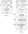
Figure 11 A and 11B are that expression beginning signal generates the process flow diagram that counter is set the order of handling, and Figure 11 A represents that yellow beginning signal generates the situation of counter, and Figure 11 B represents that the image beginning signal of magenta generates the situation of counter.
Figure 12 A and 12B are that expression beginning signal generates the process flow diagram that counter is set the order of handling, and Figure 12 A represents that the beginning signal of cyan generates the situation of counter, and Figure 12 B represents that the image beginning signal of black generates the situation of counter.
Figure 13 is the beginning signal (TOP that expression relates to the colour print that the image processing system 100 of the 2nd form of implementation of the present invention carries out
*) precedence diagram that generates.
Figure 14 is the block diagram that the expression video data request signal corresponding with (yellow, magenta, cyan, the black) of all kinds of the image processing system 100 of Figure 13 generates the circuit structure of counter.
Figure 15 A, Figure 15 B is that the beginning signal that expression is duplicated in the action continuously generates the process flow diagram that counter is set the order of handling, Figure 15 A represents that the beginning signal of the yellow in the duplicating action continuously generates the situation of counter, and Figure 15 B represents that the continuous image beginning signal that duplicates the magenta in moving generates the situation of counter.
Figure 16 A, Figure 16 B is that the beginning signal that expression is duplicated in the action continuously generates the process flow diagram that counter is set the order of handling, Figure 16 A represents that the beginning signal of the cyan in the duplicating action continuously generates the situation of counter, and Figure 16 B represents that the continuous image beginning signal that duplicates the black in moving generates the situation of counter.
Embodiment
The present invention is elaborated the accompanying drawing that reference table illustrates its best form of implementation.In the accompanying drawings, run through institute's drawings attached all components identical represent by identical reference number with parts, and omit its repeat specification.
Fig. 1 is the figure of schematic cross-section that expression relates to the image processing system of the 1st form of implementation of the present invention.Image processing system 100 its configuration examples that relate to this form of implementation comprise as being duplicating machine: the scanner unit 1 with laser cell (following abbreviation laser instrument) 6, prismatic polygon mirror (polygon prism) 7, motor of scanning device 8, signal beam detection (BD signal) generation circuit 200; Photosensitive drums 3, intermediate transfer belt 4, girth detecting sensor 5 and have the development spinner 10 of developer unit 10a~10d of all kinds; Secondary transfer roller 11; Environmental sensor 13; Cleaning balde 14,15; Fuser 16; The recording medium 17 of recording chart etc.; Paper feeding cassette 18; Hand send pallet 19 and exit slot 20.Below, in this form of implementation and the 2nd form of implementation described later, describe with the center that is controlled to be, omitted from the diagram and the explanation of the original copy reading mechanism of the original copy reading images of duplicating object about the color alignment of the sub scanning direction of all kinds of the yellow (Y) of image processing system 100, magenta (M), cyan (C), black (BK).
The structure of the each several part of image processing system 100 is described.In scanner unit 1, laser instrument 6 sends modulated laser according to the picture signal of sending from image processing system 27 shown in Figure 4 described later.Prismatic polygon mirror 7 laser that to be deflection send from laser instrument 6 and in photosensitive drums 3 scannings forms the polygonal rotating mirror of electrostatic latent image on this photosensitive drums 3.Motor of scanning device 8 rotations drive prismatic polygon mirror 7.The laser that signal beam detection generation circuit 200 detects by the main scanning direction of polygon prism 7 deflections.Development spinner 10 passes through the developer unit 10a of all kinds of yellow (Y), magenta (M), cyan (C), black (BK), 10b, and 10c, 10d develops to the electrostatic latent image that forms on the photosensitive drums 3.Photosensitive drums 3 will be by the developer primary transfer on the photosensitive drums 3 of development spinner 10 developments to intermediate transfer belt 4.Secondary transfer roller 11 and intermediate transfer belt 4 butts, with the developer secondary transfer printing on the intermediate transfer belt 4 to the recording medium of the recording chart that send pallet 19 to send from paper feeding cassette 18 or hand etc.Girth detecting sensor 5 detects the girth as the length of the circumferencial direction (sense of rotation) of intermediate transfer belt 4, is positioned at the mensuration circuit 300 of the unit internal configurations of intermediate transfer belt 4.In this form of implementation, for example optical reflection type sensor is as girth detecting sensor 5.
The action of the each several part of image processing system 100 then, is described.At first, carry out the image formation of the data of yellow (Y).Promptly, receive the user forms operation through the image of the not shown operating portion input of image processing system 100 the indication that begins, after carrying out the initialization action of image formation preparation, with the signal that begins based on establishing by cable of program generation is triggering, makes beginning signal shown in Figure 4 described later form the not shown beginning (TOP by every look target setting value of equipment in the device 22
*) startup of signal generation counter, the value that generates counter at the ITOP signal of the yellow (Y) of the 1st look generates the beginning signal of yellow (Y) when arriving desired value, receive this beginning signal, write timing as the laser instrument 6 in the scanner unit 1, penetrate laser from laser instrument 6, thus photosensitive drums 3 is write the sub-image of the data of yellow (Y).
Then, by not shown driving mechanism rotating photosensitive drum 3, on the developer unit 10a position contacting of the yellow (Y) in photosensitive drums 3 and development spinner 10, make image development on the photosensitive drums 3 by the developer of yellow (Y).And, by driving mechanism rotating photosensitive drum 3, on photosensitive drums 3 and intermediate transfer belt 4 position contacting, middle transfer belt 4 is carried out the primary transfer of the developer of the yellow (Y) on the photosensitive drums 3.Here, about 90 degree of development spinner 10 rotations, the development of preparing Next magenta (M).
Then, in the image of the data of magenta (M) forms, the beginning signal that generates when forming with the data image of yellow (Y) is triggering, with above-mentioned same, make beginning signal shown in Figure 4 form the not shown beginning signal generation counter startup by every look target setting value of equipment in the device 22, the value that generates counter at the beginning signal of the magenta (M) of the 2nd look generates the beginning signal of magenta (M) when arriving desired value, receive this beginning signal, as the write timing of the laser instrument 6 in the scanner unit 1, penetrate laser from laser instrument 6.When the write timing identical position of position of rotation the time of middle transfer belt 4, penetrate laser writes the data of magenta (M) to photosensitive drums 3 sub-image from laser instrument 6 with yellow (Y).
Then, by above-mentioned driving mechanism rotating photosensitive drum 3, the place identical when yellow (Y) with the position of rotation of intermediate transfer belt 4, the developer by magenta (M) makes the image development on the photosensitive drums 3.And by driving mechanism rotating photosensitive drum 3, the place identical with the position of rotation of intermediate transfer belt 4 when yellow (Y) is in the primary transfer of the developer that carries out the magenta (M) on the photosensitive drums 3 on the intermediate transfer belt 4.
Then, about cyan (C), black (BK), control by forming operation with above-mentioned same image, on intermediate transfer belt 4, overlap the developer part of 4 looks of yellow (Y), magenta (M), cyan (C), black (BK), send pallet 19 to supply with recording chart 17 from paper feeding cassette 18 or hand, with secondary transfer roller 11 and intermediate transfer belt 4 butts.Thus, by secondary transfer roller 11, the developer secondary transfer printing on the intermediate transfer belt 4 is to recording chart 17.Here, leave in the moment that whole developers is transferred on the recording chart 17 with the secondary transfer roller 11 of intermediate transfer belt 4 butts.And the developer on the recording chart 17 passes out to exit slot 20 by fuser 16 photographic fixing with the recording chart 17 of finishing image formation.
Cleaning action by 15 pairs of middle transfer belt 4 of cleaning balde described later is described here.The pre-treatment that forms as the image that carries out 4 looks as described above for carrying out the cleaning of intermediate transfer belt, before the development as the yellow (Y) of the 1st look, makes cleaning balde 15 butt intermediate transfer belts 4.The cleaning balde 15 of butt is before the developer front end of the yellow (Y) of 1st look of primary transfer to the intermediate transfer belt 4 arrives the position of cleaning balde 15, and cleaning balde 15 leaves intermediate transfer belt 4, finishes the pre-treatment of cleaning.In addition, as mentioned above, overlap the developer of 4 looks, the developer secondary transfer printing is a residual developer on the cleaning intermediate transfer belt 4 to recording chart 17 time, and the butt cleaning balde 15 once more, clear away whole developers, leave from middle transfer belt 4 this moment, finishes the aftertreatment of cleaning.
In addition, the result's decision that detects according to the girth that carries out intermediate transfer belt 4 by the girth detecting sensor 5 of the unit internal configurations of intermediate transfer belt 4 by every look target value set of above-mentioned yellow (Y), magenta (M), cyan (C), black (BK).
The following describes this girth detection method.
Fig. 2 is the block diagram of inner structure of mensuration circuit 300 of the image processing system 100 of presentation graphs 1.
Among Fig. 2, measure girth detection counter 307 and above-mentioned girth detecting sensor 5 shown in Figure 1 that circuit 300 comprises oscillator 301, frequency divider 302, CPU306, has counter portion 303 and girth register portion 304, measure the girth of intermediate transfer belt 4.
The action of this structure is described, the primary clock to frequency divider 302 input oscillators 301 generate generates girth by frequency divider 302 and detects the reference clock of using counter 307.Girth detects with counter 307 and is connected with CPU306, CPU306 can read in girth through bus always and detect the count value of using the counter portion 303 of loading in the girth register portion 304 of counter 307, generates the enable signal of girth detection with the counter portion 303 of counter 307.
The counter portion 303 that girth detects with counter 307 is triggering with the enable signal of CPU306 and the detection signal of girth detecting sensor 5, the counting of beginning reference clock, during from girth detecting sensor 5 next detection signal of input, the count value of this moment is loaded into girth register portion 304, but also empty this counter portion 303, count repeatedly again.That is, counter portion 303 measures the time the 2nd detection signal that obtains from the 1st detection signal that obtained by girth detecting sensor 5 to the circular motion along with intermediate transfer belt 4.
The setting order of the realistic objective value of setting by every look of yellow (Y), magenta (M), cyan (C), black (BK) with the said structure of image processing system 100 then, is described.At first, do not produce during initialization action when the power supply of image processing system 100 inserts etc. in the timing that middle transfer belt 4 images is formed caused physical shock (for example the impact of leaving along with the butt of transfer belt 4 in the middle of 11 pairs of cleaning balde 15 or the secondary transfer roller etc.), use girth detecting sensor 5 and girth detect with counter 307 detect intermediate transfer belt 4 girth the girth detection in proper order.
Fig. 3 is that the girth of key diagram 2 detects the figure with the action of counter 307.At first, circular motion along with intermediate transfer belt 4, by the reference mark 12 on the inside surface of girth detecting sensor 5 detection intermediate transfer belts 4, detect counter portion 303 with counter 307 from girth detecting sensor 5 input detection signals (HP signal) by girth, begin the input girth is detected initial reference clock counting with counter 307 from the rising edge of detection signal.When intermediate transfer belt 4 further carries out circular motion, by girth detecting sensor 5 detection reference mark 12 once more, count with above-mentioned detection signal (HP signal) the reference clock number before that is produced that detects once more of 303 pairs of inputs of counter portion of counter 307 by the girth detection, count value at this moment is loaded into girth detects in the girth register portion 304 that uses in the counter 307.
By the count value that as above obtains, can detect the girth of measuring intermediate transfer belt 4 with the resolution unit of the reference clock of counter 307 by girth, the peripheral speed (speed of circumferentially moving) of the intermediate transfer belt 4 when therefore forming according to the girth of intermediate transfer belt 4 and image can be managed 1 time-of-week of intermediate transfer belt 4.But, in fact, as described later, because to the physical shock of middle transfer belt 4 (for example the impact of leaving along with the butt of transfer belt 4 in the middle of 11 pairs of cleaning balde 15 and the secondary transfer roller etc.), 1 time-of-week of intermediate transfer belt 4 of all kinds was for there being the value of biasing to above-mentioned 1 time-of-week of calculating when image formed.Importing the additional respectively above-mentioned bias of desired value of all kinds of ITOP signal generation counter (signal generating apparatus) of all kinds when therefore, image forms sets.
The computing method of this bias are just like inferior method: when for example factory appears on the scene, by each circular motion respectively make intermediate transfer belt 1 week of 4 circular motion during make the butt of cleaning balde 15, secondary transfer roller 11 leave, the poor Δ of 1 time-of-week under the situation that itself and the butt that does not carry out cleaning balde 15, secondary transfer roller 11 are left is calculated as bias, and it is stored in the device; Certain predetermined value is carried out initial setting as bias, image form in the action by cleaning balde 15, secondary transfer roller 11 not the timing left of butt begin the action of girth detecting sensor 307 equally by CPU306, measure the girth of intermediate transfer belt 4, the poor Δ of itself and the former's measured value is calculated as bias, make the initial setting setting value reflect and be stored in the device.
In addition, the desired value of beginning signal generation counter (signal generating apparatus) can independently be set by 4 looks of yellow (Y), magenta (M), cyan (C), black (BK).In addition, can by the corresponding A face of the recording chart of opening with the odd number that is attached on the intermediate transfer body 4 with and set with independent with the corresponding B face of recording chart that the even number that is attached on the intermediate transfer body 4 is opened.
But, only correctly make yellow (Y), magenta (M), cyan (C), black (BK) beginning of all kinds (becoming the picture beginning that image forms front end regularly) position synchronously, the beginning signal (TOP that writes out of the sub scanning direction that the expression that the rotation by intermediate transfer belt 4 is obtained is of all kinds
*) synchronous with the signal beam detection that writes out (Beam Detect (BD) signal) of the expression that obtains by the rotation of motor of scanning device 8 main scanning direction of all kinds, writing out the position and may producing the beginning signal of all kinds and the phase differential of BD signal of sub scanning direction then of all kinds promptly produces the deviation of 1 row on maximum sub scanning direction.This problem can be resolved when the time (cycle) that intermediate transfer belt 4 moved for 1 week is the integral multiple in cycle of BD signal just.But usually, the cycle that makes intermediate transfer belt 4 just produces restriction for the integral multiple in cycle of BD signal to the design of image processing system 100, is difficult therefore.
Therefore, in this form of implementation, use known prior art, whenever moved for 1 week with intermediate transfer belt 4, regenerate echo signal as the benchmark corresponding with the position of polygon prism 7 on the motor of scanning device 8, this echo signal is applied the simple structure that phase control is come Spin Control motor of scanning device 8, can provide thus do not have yellow (Y) fully, the image processing system 100 of the polychrome (panchromatic) of the registration deviation of all kinds of magenta (M), cyan (C), black (BK).
Fig. 4 is the block diagram of the structure of the presentation video motor of scanning device control system that forms device 100.Image processing system 100 comprises laser instrument 6, prismatic polygon mirror 7, has the motor of scanning device 8 of motor of scanning device driving circuit 8-1 and motor of scanning device main body (SM) 8-2, circuit 200 takes place for CPU21, beginning signal generating unit 22, timer 23, ROM24, oscillator 25, laser control device 26, image forming part (image formation control circuit) 27, drum motor control device 28, motor of scanning device control circuit 29, oscillator 30, signal beam detection (BD signal).Among Fig. 4, the structure identical with above-mentioned Fig. 1 adds same numeral.
CPU21 is responsible for the control that entire image forms device 100 according to program stored among the ROM24, detects and handles shown in execution each process flow diagrams described later such as counter 307, environmental sensor 13 by control CPU306, girth.CPU21 has not shown storer (perform region of CPU21) in CPU21 inside or other positions.ROM24 is the storer of storage by the various control programs of CPU21 execution.Drum motor control device 28 makes intermediate transfer belt 4 and photosensitive drums 3 rotate/stop.Beginning signal generating unit is stated 1 week of bright predetermined intermediate transfer belt 4 more than 22 step number and 1 cycle length start timer 23 for the basis, generate beginning signal (TOP of all kinds in electric mode when the image of reality forms
*).
Motor of scanning device 8 attaches above-mentioned polygon prism shown in Figure 17 is set, and has motor of scanning device driving circuit 8-1 and motor of scanning device main body (SM) 8-2, according to the instruction of CPU21, rotates/stops by the control of motor of scanning device control circuit 29.Circuit 200 takes place along with the rotation of polygon prism 7 detects laser by polygon prism 7 deflections in signal beam detection (BD signal), generates the signal beam detection (BD signal) as the beginning reference signal (synchronizing signal of main scanning direction) of main scanning direction.About this signal beam detection (BD signal), with 6 prismatic polygon mirror during as polygon prism 7,1 week of motor of scanning device 8 produces 6 signal beam detections (BD signal).
Oscillator 30 generates the reference clock that makes image forming part (image formation control circuit) 27 actions.Image forming part 27 is made of subscan control circuit and main sweep control circuit, by generating the timing that video data (video data) forms usefulness with communicating by letter of not shown controller, according to beginning signal (TOP
*) and signal beam detection (BD signal) make subscan and main sweep synchronous, generate the lasing fluorescence signal of corresponding vision signal.Laser control apparatus 26 is by the print command of CPU21 and the beginning signal (TOP of beginning signal generating unit 22
*) carry out the synchronous of sub scanning direction of all kinds, control the driving of laser instrument 6.Laser instrument 6 receives the signal of laser control apparatus 26, by laser the sub-image data is write photosensitive drums 3.Motor of scanning device control circuit 29 has control circuit, and it moves and makes at the electric beginning signal (TOP of generation
*) produce the target BD signal of making to become target afterwards, make it to disappear with the phase differential of actual BD signal.
Fig. 5 is the block diagram of the detailed structure of expression motor of scanning device control circuit 29 shown in Figure 4.Motor of scanning device control circuit 29 comprises counter 31, phase-comparison circuit 34, charge pump (charge pump) circuit 35.22 is above-mentioned beginning signal generating units shown in Figure 4 among the figure, the 2nd, and the BD signal in the motor of scanning device control circuit 29, the 33rd, the target BD signal in the motor of scanning device control circuit 29.In Fig. 5, the structure identical with above-mentioned Fig. 4 adds same numeral.
The target BD signal 33 that the counter 31 of motor of scanning device control circuit 29 produces as target.Motor of scanning device control circuit 29 has following structure, particularly at the output (TOP that detects beginning signal generating unit 22
*) after, the counter 31 that makes target BD signal generate usefulness resets, and regenerates target BD signal.The phase place of the target BD signal 33 that phase-comparison circuit 34 is relatively produced by the counter 31 and phase place of the BD signal 2 of the reality that circuit 200 produces takes place by signal beam detection (BD signal) is exported LAG signal described later, LEAD signal.The output signal of charge pump circuit 35 receiving phase comparator circuits 34 is changed to control voltage with the phase difference variable of above-mentioned two signals.Here, the time former state of phase differential as controlled quentity controlled variable, is moved in proportion, so charge pump circuit 35 produces voltages control voltage certain, have "+"/"-" according to " shifting to an earlier date "/" hysteresis " of phase differential.
Fig. 6 is the block diagram of the detailed structure of the motor of scanning device control Driver Circuit in the motor of scanning device 8 of presentation graphs 4.Motor of scanning device 8 has motor of scanning device driving circuit 8-1, motor of scanning device main body (SM) 8-2, frequency divider 41, speed arbiter 42, resistance 43, integrator 44, integration filter 45, control amplifier 46, resistance 48.25 is above-mentioned oscillators shown in Figure 4 among the figure.Structure identical with above-mentioned Fig. 4 among Fig. 6 adds same numeral.
The motor of scanning device control Driver Circuit of Gou Chenging is to use the control signal from above-mentioned motor of scanning device control circuit 29 shown in Figure 4, the control circuit of controlling and driving motor of scanning device main body (SM) 8-2 like this.Frequency divider 41 frequency dividing ratio is in accordance with regulations carried out frequency division to the reference clock of oscillator 25, becomes the frequency of the datum velocity of motor of scanning device driving circuit 8-1.Speed arbiter 42 relatively be used to detect the polygon prism 7 (with reference to figure 1) that is attached on the motor of scanning device 8 rotational speed BD signal 2 and become the output signal of frequency divider 41 of frequency of the datum velocity of polygon prism 7, according to the speed of comparative result judgement polygon prism 7.
The control action of motor of scanning device 8 then, is described.When carrying out the spinning movement of motor of scanning device 8 with the motor of scanning device control Driver Circuit of said structure, speed arbiter 42 judges by monitoring BD signal 2 whether motor of scanning device 8 is the rotational speed of being scheduled to, improve rotational speed by producing when motor of scanning device 8 does not reach predetermined rotational speed, exceed at motor of scanning device 8 under the situation of predetermined rotational speed, the feedback control loop that produces the output signal that reduces rotational speed is rotated control.Wherein, in this feedback control loop, because not based on the BD signal with as the control of the phase differential of the output signal of the frequency divider 41 of the frequency that becomes the said reference rotational speed, so by the bias voltage of integrator 44, motor of scanning device 8 is controlled as the rotational speed that departs from slightly with predetermined rotational speed.
For motor of scanning device 8 being controlled to be reliably predetermined speed as target, the above-mentioned target BD signal 33 that is obtained by motor of scanning device control circuit 29 shown in Figure 5 is with the phase differential output of actual BD signal 2 and be input in the integrator 44 through the input of resistance 48/ through resistance 43, makes and need carry out PLL (Phase Locked Loop) speed control.Here, the gain that the gain of PLL control loop can specific rate arbiter 42 is much lower, and resistance 48 is compared with resistance 43, can be set at for example resistance value more than 10 times.This is because the gain of PLL control when high is good to the tracing property of target phase, on the contrary, and to the introducing variation of the lock-out state of PLL.By adding the PLL control of this target BD signal 33 and the phase differential of actual BD signal 2, can be used on the rotational speed that the rotational speed that produces actual BD signal 2 in cycle of target BD signal 33 is come gated sweep device motor 8.
Then, use the timing diagram of Fig. 7 to describe the PLL control action that image forms device 100 in detail.
Fig. 7 is the timing diagram to the PLL control action of motor of scanning device 8 that the motor of scanning device control circuit 29 of presentation graphs 4 carries out.
In Fig. 7, ENABLE
*Be the signal of expression print area/nonprinting region (the non-sub-image of the sub scanning direction of photosensitive drums 3 forms the zone), " High " of blacking interval expression print area among the figure, region representation nonprinting region in addition.TOP
*Be beginning (TOP) signal, print the synchronizing signal of beginning, generate by beginning signal generating unit 22 as sub scanning direction.REFBD
*Be target BD signal, by counter 31 generations of motor of scanning device control circuit 29.BD
*Be actual BD signal, print the synchronizing signal of beginning, by signal beam detection (BD signal) circuit 200 takes place and generate as main scanning direction.LAG
*Be the LAG signal, represent actual BD signal (BD
*) phase place to target BD signal (REFBD
*) delay, by phase-comparison circuit 34 output of motor of scanning device control circuit 29.
LEAD
*Be the LEAD signal, the BD signal (BD that expression is actual
*) to target BD signal (REFBD
*) phase place in advance, by phase-comparison circuit 34 outputs of motor of scanning device control circuit 29.In addition, this LAG signal (LAG
*) at the BD of reality signal (BD
*) phase place than target BD signal (REFBD
*) phase delay the time be " Low ".LEAD signal (LEAD
*) at the BD of reality signal (BD
*) phase place than target BD signal (REFBD
*) phase place be " Low " when shifting to an earlier date.CPUMP is the LAG signal (LAG from phase-comparison circuit 34 outputs of motor of scanning device control circuit 29
*) and LEAD signal (LEAD
*) composite signal, generate by the charge pump circuit 35 of motor of scanning device control circuit 29.Is represents actual electric current to motor of scanning device main body 8-2 output.
Then, use Fig. 7 that the PLL control action of the motor of scanning device control Driver Circuit (frequency divider 41~resistance 48) in the above-mentioned motor of scanning device 8 shown in Figure 6 is described.
At first, among Fig. 7, at TOP signal (TOP
*) produce by beginning signal generating unit 22 before, motor of scanning device 8 judges that by speed control and PLL control rotational speed, makes target BD signal (REFBD
*) and actual BD signal (BD
*) the phase place unanimity.
Then, when producing TOP signal (TOP
*) time, at beginning signal (TOP
*) negative edge, empty immediately and generate target BD signal (REFBD
*) the counter 31 of motor of scanning device control circuit 29, counter 31 restarts the counting action, and regenerates new target BD signal (REFBD
*).Actual BD signal (BD
*) because the speed of motor of scanning device 8 drastic change and continuing not by original cycle output.The phase-comparison circuit 34 of motor of scanning device control circuit 29 is only at the BD of reality signal (BD
*) phase place than target BD signal (REFBD
*) phase delay the time, with LAG signal (LAG
*) be made as " Low " and output, only at the BD of reality signal (BD
*) phase place than target BD signal (REFBD
*) phase place when shifting to an earlier date, with LEAD signal (LEAD
*) be made as " Low " and output.
That is, the output of the phase-comparison circuit 34 of motor of scanning device control circuit 29 is at the BD of reality signal (BD
*) phase place than target BD signal (REFBD
*) phase delay the time, LAG signal (LAG
*) be " Low ", LEAD signal (LEAD
*) still be " High ", at the BD of reality signal (BD
*) phase place than target BD signal (REFBD
*) phase place when shifting to an earlier date, LEAD signal (LEAD
*) be " Low ", LAG signal (LAG
*) still be " High ".
LAG signal (the LAG of the charge pump circuit 35 synthetic expression phase delays of motor of scanning device control circuit 29
*) and represent the LEAD signal (LEAD that phase place shifts to an earlier date
*), generate the CPUMP signal.Here, the charge pump circuit 35 of motor of scanning device control circuit 29 constitutes: when phase delay, need accelerated scan device motor 8, therefore output "+" voltage when phase place shifts to an earlier date, needs deceleration motor of scanning device 8, therefore output "-" voltage.
Such control signal as the result that the signal relevant with PLL control adds in the interior motor of scanning device control Driver Circuit of the motor of scanning device 8 of above-mentioned Fig. 6 is, motor of scanning device 8 is added the control that its speed is quickened than present speed a little, make phase delay reduce at leisure, continue to control up to the position that keeps balance.That is feasible actual BD signal (BD,
*) and target BD signal (REFBD
*) phase-locking, velocity contrast is entirely zero, its phase differential is offset the velocity deviation of the speed arbiter 42 in the above-mentioned motor of scanning device 8, is stabilized in the position that keeps balance.
At the BD of reality signal (BD
*) and target BD signal (REFBD
*) phase place keep the moment of balance to begin to print, then can correctly make print position of all kinds (printing initiating position of sub scanning direction) consistent each other.And, owing to print motor of scanning device control circuit 29 effects in the action, feasible actual BD signal (BD
*) and target BD signal (REFBD
*) phase place keep balance, therefore to printing before the release, all the may command motor of scanning device 8, make actual BD signal (BD
*) and target BD signal (REFBD
*) synchronously.
Like this, even if intermediate transfer belt 4 moves in the image processing system 100 of the integral multiple that the time in 1 week is not set at the BD cycle, also can make the main sweep synchronizing signal consistent with subscan synchronizing signal (beginning signal) phase place.
Then, describe internal action and effect in the image processing system 100 of this form of implementation in detail with said structure.
Beginning signal (the TOP of Fig. 8 colour print that to be expression undertaken by the image processing system 100 of Fig. 1
*) figure of the order that generates.The intermediate transfer belt 4 that uses in the present embodiment can paste 2 for example recording charts of A4 size (will the image corresponding with 2 recording charts being formed at the processing on the intermediate transfer belt 4 simultaneously) on 1 girth, Fig. 8 represent to paste in the small size recording chart of 2 A4 etc. colour system as the time order.What the following describes in addition, is that the counter of all kinds of beginning is arranged in the beginning signal generating unit 22 with yellow A face (YA) counter, yellow B face (YB) counter.
Among Fig. 8, at first, be triggering, make yellow A face (YA) counter, yellow B face (YB) counter begin counting simultaneously with the electric START signal that generates according to program.Here, so-called A face (face that the odd number of recording chart is opened) is the first half in 1 week of intermediate transfer belt 4, and so-called B face (face that the even number of recording chart is opened) is the latter half in 1 week of intermediate transfer belt 4.As shown in the figure, through the preset count time (TYA, in the time of TYB), generate respectively as with the corresponding beginning signal (TOP of A face, B face of yellow (Y)
*) VYA
*Signal, VYB
*Signal receives this signal, as the write timing of the laser instrument 6 in the scanner unit 1, penetrates laser from laser instrument 6.Thus, on photosensitive drums 3, write the sub-image of the data of yellow (Y).
Follow VYA with yellow (Y)
*Signal, VYB
*Signal is for triggering, and the preset count time that continues 1 time-of-week of about intermediate transfer belt 4 in process, (TMA in the time of TMB), generated as the beginning signal (TOP corresponding with A face, the B face of magenta (M) respectively
*) VMA
*Signal, VMB
*Signal receives this signal, obtains the write timing of the laser instrument 6 in the scanner unit 1, penetrates laser from laser instrument 6.Thus, the sub-image that photosensitive drums 3 is carried out the data of magenta (M) writes.
Then, cyan (C), black (BK) are also carried out and above-mentioned same control, the sub-image that photosensitive drums 3 is carried out the data of cyan (C), black (BK) writes.Behind the developer that has overlapped 4 looks on the intermediate transfer belt 4, use according to beginning signal (TOP as black (BK)
*) VKA
*Signal, VKB
*The registration roller ON counter that signal is counted, generate the location respectively in turn and connect (registration-on) signal (RA, RB), send pallet 19 that recording chart 17 is provided from paper feeding cassette 18 or hand, by making secondary transfer roller 11 butts, with the developer secondary transfer printing of 4 looks on the intermediate transfer belt 4 to recording chart 17.
Fig. 9 is the figure that the expression video data request signal corresponding with (yellow, magenta, cyan, the black) of all kinds of the image processing system 100 of first embodiment generates the circuit structure of counter.Among Fig. 9, as mentioned above, become yellow A face (YA) counter and yellow B face (YB) counter input START signal to the 1st look, for following later counter of the same colour, with the beginning signal that is generated by preceding counter of the same colour serves as to start the cascade structure that triggers, the feasible order that can carry out first embodiment.
Then, Figure 10 represents with above-mentioned Fig. 1, Fig. 2, Fig. 4, Fig. 5, the beginning signal genesis sequence of the structure of image processing system 100 shown in Figure 6 and above-mentioned colour print shown in Figure 8 is the basis, consider image processing system 100 actual systems as the time produce physical shock (for example on intermediate transfer belt 4, form toner as the time, make cleaning balde 15 leave the physical shock that is produced when waiting), the order of the picture beginning timing in the colour print of the reality of being undertaken by image processing system 100.
Figure 10 be to the order of above-mentioned Fig. 8 further added present embodiment to the timing of the physical shock of intermediate transfer belt 4 and real screen beginning regularly the precedence diagram corresponding with it.As shown in the figure, the actual system of image processing system as the time, pre-treatment as the system picture that carries out above-mentioned 4 looks, cleaning for intermediate transfer belt 4, and the cleaning balde 15 that butt leaves intermediate transfer belt in yellow (Y) B face system picture second half section regularly, as the aftertreatment of cleaning, at black (BK) B face system picture second half section and intermediate transfer belt 4 butts regularly.In addition, secondary transfer roller 11 is transferred to timing on the recording chart (illustrated black (BK) A face system picture second half section regularly) and intermediate transfer belt 4 butts at the developer that coincides with 4 looks on the intermediate transfer belt 4 also as mentioned above.
In fact,, on the direction that the loading moment of intermediate transfer belt 4 reduces, act on intermediate transfer belt 4 instantaneous rapid circular movements (to the action of the circumferencial direction of intermediate transfer belt) by the butt departure motion of transfer belt 4 in the middle of 15 pairs of the cleaning baldes.On the contrary, the leaving in the butt action of transfer belt 4 in the middle of 15 pairs of cleaning baldes acts on the direction that the loading moment of intermediate transfer belt 4 increases, and intermediate transfer belt 4 is instantaneous to rotatablely move lentamente.And in secondary transfer roller 11 during to intermediate transfer belt 4 butts, still act on the direction that the loading moment of intermediate transfer belt 4 increases, similarly, intermediate transfer belt 4 is instantaneous to rotatablely move lentamente.
Therefore, the driving of each load (cleaning balde 15, secondary transfer roller 11) by above-mentioned machinery, the circumferential movement of intermediate transfer belt 4 changes, the result, actual picture beginning regularly changes before and after as shown in the figure.In this order, actual picture beginning of all kinds is regularly irrelevant with above-mentioned load variations, depends on by beginning signal (TOP of all kinds
*) to generate the beginning signal of all kinds that counter generates (be TOP in the present embodiment
*), so as shown in the figure, in the picture beginning regularly of reality, only produce departing from of Δ L, in the system picture action of 4 looks, the registration deviation among the image formation result who causes full-color image formation device 100 that adds up who departs between this every look.Specifically, as shown in the figure, because cleaning balde 15 leaves from middle transfer belt 4,1 time-of-week in the yellow on the intermediate transfer belt 4 (Y)-magenta (M) zone all shortens Δ Ly-c at A face, B face, by the butt of 11 pairs of middle transfer belt 4 of secondary transfer roller, the 1 time-of-week lengthening Δ Lc-k in the cyan of intermediate transfer belt 4 (C)-black (BK) zone.The registration deviation amount of the reality that this time variation amount causes is about 50 μ m~100 μ m.(in the present embodiment, the departure motion influence of action of the butt of cleaning balde 15 and secondary transfer roller is less, therefore omits diagram and explanation.)
But, the generation of leaving the butt of transfer belt 4 causes in the middle of 11 pairs of the impact, the secondary transfer roller that are caused impact etc. of transfer belt 4 is regularly constant in system picture order in the middle of 15 pairs of the cleaning baldes of above-mentioned explanation, and the circumferential movement of the intermediate transfer belt 4 of the above-mentioned reality that impact produced changes also tendentiousness.
Figure 11 A~11B and Figure 12 A~12B are that expression beginning signal generates the process flow diagram that counter is set the order of handling, Figure 11 A represents that yellow beginning signal generates the situation of counter, Figure 11 B represents that the image beginning signal of magenta generates the situation of counter, Figure 12 A represents that the beginning signal of cyan generates the situation of counter, and Figure 12 B represents that the image beginning signal of black generates the situation of counter.
At first shown in Figure 11 A, when carrying out the setting of yellow (Y) counter (step S100 is for being), irrelevant with the girth of intermediate transfer belt 4, the time of the image beginning signal from the START signal to yellow (Y) is certain, therefore sets preset count device value TYA, the preset count device value TYB (step S101) that the B face is used that the A face of intermediate transfer belt 4 is used respectively.
Then shown in Figure 11 B, when carrying out the setting of magenta (M) counter (step S111 is for being), the girth that detects intermediate transfer belt 4 as the girth detecting pattern after (step S112 is for being) (behind the so-called girth detecting pattern here, after being meant the girth mensuration end of intermediate transfer belt 4, after being actually the perimeter value of girth detection of sensing Fig. 2 with girth register portion 304 storing measurements in the counter 307), use in the girth register portion 304 of counter 307 being stored in the girth detection, the girth of the intermediate transfer belt of being measured by girth detecting sensor 54 stores among the RAM (omitting diagram) of CPU306 (step S113).Then, by the girth and the predetermined picture formation speed of the intermediate transfer belt among the RAM that is stored in CPU306 4, calculate Counter Value TMA, the TMB (step S114) suitable with 1 time-of-week of intermediate transfer belt 4.Then, respectively to the side-play amount Mcl-off of the circumferential movement transformation period of the additional intermediate transfer belt 4 corresponding of TMA, TMB, desired value TMA ', the TMB ' of magenta (M) counter is individually set to the A face with, B face usefulness (step S115) with the physical shock of cleaning balde 15 when middle transfer belt 4 is left.
Then shown in Figure 12 A, when carrying out the setting of cyan (C) counter (step S121 is for being), behind the girth detecting pattern of the girth that detects intermediate transfer belt 4 (step S122 is for being), detect girth with being stored in girth, store among the RAM (omitting diagram) of CPU306 (step S123) with intermediate transfer belt 4 in the girth register portion 304 of counter 307, that measure by girth detecting sensor 5.Then, by the girth and the predetermined picture formation speed of the intermediate transfer belt among the RAM that is stored in CPU306 4, calculate the Counter Value TCA suitable, TCB (step S124) with 1 time-of-week of intermediate transfer belt 4.Form operation about the image between magenta (M)-cyan (C), owing to there not be the physical shock of expection, so desired value TCA, the TCB of cyan (C) counter is individually set to the A face with, B face usefulness.
At last, shown in Figure 12 B, when carrying out the setting of black (BK) counter (step S131 is for being), behind the girth detecting pattern of the girth that detects intermediate transfer belt 4 (step S132 is for being), detect girth with being stored in girth, store among the RAM (omitting diagram) of CPU306 (step S133) with intermediate transfer belt 4 in the girth register portion 304 of counter 307, that measure by girth detecting sensor 5.Then, by the girth and the predetermined picture formation speed of the intermediate transfer belt among the RAM that is stored in CPU306 4, calculate Counter Value TKA, the TKB (step S134) suitable with 1 time-of-week of intermediate transfer belt 4.About the A face of intermediate transfer belt 4,, the desired value TKA of black A face (BA) counter is set to A face usefulness (step S135) owing to there is not the physical shock of expection.On the other hand, use about the B face, to TKB additional with secondary transfer roller 11 the side-play amount Kcl-on of the circumferential movement transformation period of the corresponding intermediate transfer belt 4 of the physical shock during from middle transfer belt 4 butts, the desired value TKB ' of black (BK) counter is set to B face usefulness (step S136).
By setting the desired value that illustrates with above-mentioned Figure 11 A, 11B, 12A, 12B, can regularly almost synchronously generate beginning signal (TOP of all kinds to the picture beginning of the reality in the butt action of middle transfer belt 4 with departure motions that produce, 15 pairs of middle transfer belt 4 of cleaning balde, secondary transfer roller in system picture order as shown in Figure 10 as above-mentioned
*), can in image processing system 100, not cause big registration deviation, the output preferable image.
As described above, according to this first embodiment, owing to each load that is used for primary transfer (cleaning balde 15, secondary transfer roller 11 etc.) rotational speed that leaving of middle transfer belt 4 produced with butt, that can make intermediate transfer belt 4 of image forming course causes the load variations of the machinery of deviation, and make the time being engraved in 1 week of intermediate transfer belt 4 different between of all kinds, so can improve the problem that in colour superimposition operation in the past first look and second look produce registration deviation later on.
The second embodiment of the present invention then is described.The inner structure (Fig. 1) of the image processing system portion of present embodiment, the girth detection structure (Fig. 2) of counter, the structure (Fig. 4) of motor of scanning device control system, the detailed structure (Fig. 5) of motor of scanning device control circuit, the detailed structure (Fig. 6) of motor of scanning device control Driver Circuit etc. are identical with first embodiment, details as mentioned above, the Therefore, omited explanation.
Present embodiment is characterised in that, as shown in Figure 1, for can monitor humidity and temperature and calculate intermediate transfer belt 4 around amount of moisture, (for example outer circumferential side) configuration surroundings sensor 13 around intermediate transfer belt 4.That is, environmental sensor 13 detected temperatures and humidity according to the testing result of this environmental sensor 13, are calculated the amount of moisture on every side of intermediate transfer belt 4 by CPU301 (Fig. 2).
Figure 13 is the beginning signal (TOP in the colour print of image processing system 100 of expression present embodiment
*) figure of the order that generates.In a second embodiment, intermediate transfer belt 4 is the same with first embodiment, can paste 2 for example recording charts of A4 size in 1 girth, Figure 13 represent to paste 2 A4 etc. the small size recording chart colour system as the time order.
In Figure 13, at first, in the A face that generates based on program, B face, be triggering respectively with independent electric START signal, begin respectively to count with yellow A face (YA) counter, yellow B face (YB) counter.As shown in the figure, through predetermined gate time (TYA, TYB) after, generate respectively as with the corresponding beginning signal (TOP of A face, B face of yellow (Y)
*) VYA
*Signal, VYB
*Signal receives this signal, obtains the write timing of the laser instrument 6 in the scanner unit 1, penetrates laser from laser instrument 6.Thus, the sub-image that photosensitive drums 3 is carried out the data of yellow (Y) writes.
Follow VYA with yellow (Y)
*Signal, VYB
*Signal is for triggering, through preset count time of continuing 1 time-of-week of intermediate transfer belt 4 approximately (TMA, TMB) after, generate as the beginning signal (TOP corresponding respectively with A face, the B face of magenta (M)
*) VMA
*Signal, VMB
*Signal receives this signal, obtains the write timing of the laser instrument 6 in the scanner unit 1, penetrates laser from laser instrument 6.Thus, the sub-image that photosensitive drums 3 is carried out the data of magenta (M) writes.
Then, cyan (C), black (BK) are also carried out control same as described above, the sub-image that photosensitive drums 3 is carried out the data of cyan (C), black (BK) writes.After overlapping the developer of 4 looks on the intermediate transfer belt 4, use beginning signal (TOP according to black (BK)
*) VKA
*Signal, VKB
*Signal and the registration roller ON counter counted, (RA RB), send pallet 19 that recording chart 17 is provided from paper feeding cassette 18 or hand to generate the location connection signal respectively in turn, by making secondary transfer roller 11 butts, with the developer secondary transfer printing of 4 looks on the intermediate transfer belt 4 to recording chart 17.
Figure 14 is the figure that the expression video data request signal corresponding with (yellow, magenta, cyan, the black) of all kinds of the image processing system 100 of this embodiment generates the circuit structure of counter.In a second embodiment, compare further with the circuit structure (Fig. 9) of first embodiment and to have ENABLE_A in yellow (Y) the counter A of first look, the prime of B, the grid of ENABLE_B, become on/off grid respectively by (toggle) repeatedly, and respectively to A face usefulness, B face input START signal, for following later counter of the same colour, the video data request signal that former counter of the same colour generates is the cascade structure of startup triggering, thereby can carry out the order of present embodiment.
In the present embodiment, except that above-mentioned each physical shock, for the perimeter change to the intermediate transfer belt 4 that is produced because of the environment difference that forms image and take place when exporting on the recording chart of a large amount of numbers is proofreaied and correct, when the level of stating the amount of moisture that environmental sensor 13 calculates in the use exceeds predeterminated level, make the perimeter value of the intermediate transfer belt of under the girth detecting pattern of the girth that detects intermediate transfer belt 4, measuring 4 variable.By it being reflected in beginning signal (TOP of all kinds
*) generate in the desired value of counter, form in the execution of operation at the image that forms image to recording chart, can be corresponding with the perimeter change of the intermediate transfer belt 4 that changes at any time according to the variation of the amount of moisture around the intermediate transfer belt 4, also can to form the executory environmental change of operation corresponding with image.
In addition, in fact form operation by long image, image processing system 100 internal ratio normal temperature have risen when starting about about 30 degree, and humidity also changes therewith accordingly.In fact, the girth difference of intermediate transfer belt 4 (using polyamide material in the present embodiment) has the difference about several microns.
Figure 15 A, 15B, 16A, 16B is that the beginning signal that expression is duplicated in the action continuously generates the process flow diagram that counter is set the order of handling, Figure 15 A represents that the beginning signal of the yellow in the duplicating action continuously generates the situation of counter, Figure 15 B represents that the beginning signal of the magenta in the duplicating action continuously generates the situation of counter, Figure 16 A represents that the beginning signal of the cyan in the duplicating action continuously generates the situation of counter, and Figure 16 B represents that the continuous beginning signal that duplicates the black in moving generates the situation of counter.
At first shown in Figure 15 A, when carrying out the setting of yellow (Y) counter (step S141 is for being), irrelevant with the girth of intermediate transfer belt 4, the time of the beginning signal from the START signal to yellow (Y) is certain, therefore sets the predetermined Counter Value TYB (step S141) that predetermined Counter Value TYA, B face that the A face of intermediate transfer belt 4 uses used respectively.
Then shown in Figure 15 B, when carrying out the setting of magenta (M) counter (step S151 is for being), from the predetermined number (the duplicating number of recording chart) (step S152 is for being) of the every process of continuous duplicating action beginning, calculate intermediate transfer belt 4 amount of moisture (step S153) on every side according to environmental sensor 13 detected temperature and humidities.And, the residual quantity (step S154 is for being) of the amount of moisture when relatively the amount of moisture around this intermediate transfer belt of calculating 4 is with the girth that detects intermediate transfer belt 4.When the two amount of moisture produces the above residual quantity value of scheduled volume, the additional counter off-set value Thum that causes by environmental change that calculates according to off-set value Lhum on magenta count value TMA, the TMB that has configured with the girth of the corresponding intermediate transfer belt 4 of amount of moisture difference, with environmental correction the desired value TMA of counter ", TMB " respectively new settings to the A face with, B face usefulness (step S155).
Under look like shown in Figure 16 A, the 16B, about cyan (C), black (BK), also with the counting desired value of magenta (M) similarly, the counting off-set value Thum that respectively environmental change is caused append to the A face with, B face with in (the step S171 of the step S161 of Figure 16 A~165, Figure 16 B~S175).
Thus, in the present embodiment, be not only the such intermediate transfer belt 4 of the foregoing description is carried out the correction of physical shock amount, the caused picture beginning of perimeter change that environment changes the intermediate transfer belt 4 that causes in time in the time of can also be with continuous duplicate departing from regularly is corresponding, generates than above-mentioned first embodiment and regularly generates beginning signal (TOP of all kinds according to the picture beginning of reality more accurately
*), can in image processing system 100, not cause big registration deviation ground output preferable image.
As described above, according to this second embodiment, because each load that is used for primary transfer in (cleaning balde 15, secondary transfer roller 11 etc.) image forming course is left with butt etc. to middle transfer belt 4, and the rotational speed of the made intermediate transfer belt 4 that produces causes that the mechanical load of deviation changes, make the time being engraved in 1 week of intermediate transfer belt 4 different between of all kinds, therefore can improve in the past first look in the look overlapping step and second look problem that produces registration deviation later on.
The present invention is not limited to the structure of above-mentioned first and second embodiment, so long as can realize the structure of performance of the structure of function shown in the scope of claim or above-mentioned first and second embodiment, and all applicable.
In above-mentioned first and second embodiment, as the intermediate transfer body of equipment in the image processing system 100, for example understand the situation of using intermediate transfer belt 4, but the invention is not restricted to this, as the intermediate transfer body, use the situation of intermediate transfer drum also to be suitable for.
In above-mentioned first and second embodiment, for example understand the situation of in 1 girth of the intermediate transfer belt 4 of image processing system 100, pasting the recording chart of 2 A4 sizes, but the invention is not restricted to this, in the scope that does not break away from aim of the present invention, it can be arbitrarily that recording chart size and the image to middle transfer belt 4 corresponding with recording chart attach (formation) number.
In the above-described embodiments, be that situation with duplicating machine is an example as image processing system 100, but the invention is not restricted to this, except that duplicating machine, can also in printer, Multi Role Aircraft, be suitable for.
In addition, the medium of program code that has write down the software of the function that realizes the foregoing description is offered system or device, read and carry out the program code that is stored on the medium by the computing machine (or CPU, MPU etc.) of this system or device and also can realize the present invention.
At this moment, the program code of reading from medium itself is just realized the function of the foregoing description, and the medium of having stored this program code just constitutes the present invention.
As the medium of supplying with program code, can adopt floppy disk (registered trademark) for example, hard disk, CD, photomagneto disk, CD-ROM, CD-R, CD-RW, DVD-ROM, DVD-RAM, DVD-RW, DVD+RW, tape, Nonvolatile memory card, ROM, EEPROM or through the download of network etc.
Certainly, carry out the program code of reading by computing machine, not only realize the function of the foregoing description, indication according to this program code, the OS of computer run (operating system) etc. carry out part or all of actual treatment, realize that by this processing the situation of the function of the foregoing description is also contained in wherein.
And, obviously, after will writing the function expanding plate that is inserted in computing machine from the program code that the medium of medium etc. are read or connecting the storer that function expanding unit on computers possessed, indication according to this program code, this function expanding plate or CPU that the function expanding unit possessed etc. carry out part or all of actual treatment, and the situation of the function by this processings realization the foregoing description is also contained in wherein.
Claims (23)
1. image processing system, will by electric photographic type form on as supporting body as after primary transfer is to the intermediate transfer body that is driven in rotation, with above-mentioned intermediate transfer body to recording medium, form image as secondary transfer printing, comprising:
Clean the cleaning device of above-mentioned intermediate transfer surface;
With above-mentioned cleaning device and above-mentioned intermediate transfer body butt and connecing of leaving from device;
Detect the pick-up unit of length of the around the movement direction of above-mentioned intermediate transfer body; And
According to the length of the detected above-mentioned around the movement direction of the moment of above-mentioned cleaning device and above-mentioned intermediate transfer body butt/leave not being controlled control device with the length of the detected above-mentioned around the movement direction of the moment of above-mentioned cleaning device and above-mentioned intermediate transfer body butt/leave with above-mentioned connecing to the image formation timing of above-mentioned picture supporting body from device above-mentioned connecing from device.
2. image processing system according to claim 1 is characterized in that:
Above-mentioned control device comprises:
The image that generates polychrome forms the signal generating apparatus of commencing signal;
According to connecing from device not with moment of above-mentioned cleaning device and above-mentioned intermediate transfer body butt/leave length by the detected above-mentioned around the movement direction of above-mentioned detection device above-mentioned, the image of setting the above-mentioned signal generating apparatus of input forms the desired value setting device of the desired value of timing; And
According to connecing from device moment of above-mentioned cleaning device and above-mentioned intermediate transfer body butt/leave length, proofread and correct the means for correcting of above-mentioned desired value setting device target value set by the detected above-mentioned around the movement direction of above-mentioned detection device above-mentioned.
3. image processing system according to claim 1 is characterized in that above-mentioned detection device comprises:
The reference component pick-up unit of detection additional reference component on above-mentioned intermediate transfer body;
The determinator of time the 2nd detection signal that mensuration obtains from the 1st detection signal that obtained by said reference parts pick-up unit to the around the movement of following above-mentioned intermediate transfer body.
4. image processing system according to claim 2 is characterized in that, above-mentioned signal generating apparatus comprises 4 signal generating apparatus that generate yellow, magenta, cyan, each signal of black respectively,
The image that above-mentioned desired value setting device is set above-mentioned each signal forms desired value regularly.
5. image processing system according to claim 2, it is characterized in that, above-mentioned signal generating apparatus has two at least, generate and be attached to the corresponding A face of recording medium that the odd number on the above-mentioned intermediate transfer body opens respectively with signal and the corresponding B face of the recording medium signal opened with the even number that is attached on the above-mentioned intermediate transfer body, above-mentioned desired value setting device is set respectively above-mentioned A face is formed desired value regularly with signal and above-mentioned B face with the image of signal.
6. image processing system according to claim 1 is characterized in that, above-mentioned intermediate transfer body comprises band mode, drum mode.
7. image processing system, will by electric photographic type form on as supporting body as after primary transfer is to the intermediate transfer body that is driven in rotation, with above-mentioned intermediate transfer body to recording medium, form image as secondary transfer printing, it is characterized in that, comprising:
The length that detects the around the movement direction of above-mentioned intermediate transfer body is the girth pick-up unit of girth;
The image that generates polychrome forms the signal generating apparatus of commencing signal;
According to by the detected girth of above-mentioned girth pick-up unit, set the desired value setting device of the image formation desired value regularly of the above-mentioned signal generating apparatus of input; And
On above-mentioned desired value setting device target value set additional consideration the biasing attachment device of bias of load change of expection,
By the additional above-mentioned bias of above-mentioned biasing attachment device, be used to proofread and correct on above-mentioned intermediate transfer body, form as the time produced, the value of different physical shock amounts between each color.
8. image processing system, comprise with form on by electric photographic type as supporting body as primary transfer to the primary transfer portion of the intermediate transfer body that is driven in rotation with the picture secondary transfer printing of above-mentioned intermediate transfer body secondary transfer printing portion to recording medium,
This image processing system is characterised in that, also comprises:
With above-mentioned secondary transfer printing portion and above-mentioned intermediate transfer body butt and connecing of leaving from device;
Detect the pick-up unit of length of the around the movement direction of above-mentioned intermediate transfer body; And
According to connecing from device not with the length of the detected above-mentioned around the movement direction of the moment of above-mentioned secondary transfer printing portion and above-mentioned intermediate transfer body butt/leave with the length of the detected above-mentioned around the movement direction of the moment of above-mentioned secondary transfer printing portion and above-mentioned intermediate transfer body butt/leave with above-mentioned, control control device to the image formation timing of above-mentioned picture supporting body above-mentioned connecing from device.
9. image processing system according to claim 8 is characterized in that:
Above-mentioned detection device comprises:
The reference component pick-up unit of detection additional reference component on above-mentioned intermediate transfer body;
The determinator of time the 2nd detection signal that mensuration obtains from the 1st detection signal that obtained by said reference parts pick-up unit to the around the movement of following above-mentioned intermediate transfer body.
10. image processing system according to claim 8 is characterized in that:
Above-mentioned control device comprises:
The image that generates polychrome forms the signal generating apparatus of commencing signal;
According to connecing from device not with moment of above-mentioned secondary transfer printing portion and above-mentioned intermediate transfer body butt/leave length by the detected around the movement direction of above-mentioned detection device above-mentioned, the image of setting the above-mentioned signal generating apparatus of input forms the desired value setting device of the desired value of timing; And
According to connecing from device moment of above-mentioned secondary transfer printing portion and above-mentioned intermediate transfer body butt/leave length, proofread and correct the means for correcting of above-mentioned desired value setting device target value set by the detected around the movement direction of above-mentioned detection device above-mentioned.
11. image processing system according to claim 10 is characterized in that, above-mentioned signal generating apparatus comprises 4 signal generating apparatus that generate yellow, magenta, cyan, each signal of black respectively,
The image that above-mentioned desired value setting device is set above-mentioned each signal forms desired value regularly.
12. image processing system according to claim 10, it is characterized in that, above-mentioned signal generating apparatus has two at least, generate and be attached to the corresponding A face of recording medium that the odd number on the above-mentioned intermediate transfer body opens respectively with signal and the corresponding B face of the recording medium signal opened with the even number that is attached on the above-mentioned intermediate transfer body
Above-mentioned desired value setting device is set the desired value that above-mentioned A face is formed timing with signal and above-mentioned B face with the image of signal respectively.
13. the image of an image processing system forms control method, described image processing system will by electric photographic type form on as supporting body as after primary transfer is to the intermediate transfer body that is driven in rotation, with above-mentioned intermediate transfer body to recording medium, form image as secondary transfer printing, and comprise the cleaning device of cleaning above-mentioned intermediate transfer surface; With with above-mentioned cleaning device and above-mentioned intermediate transfer body butt and connecing of leaving from device;
This method comprises:
Connect from the moment of device above-mentioned, detect first girth detection step of length of the around the movement direction of above-mentioned intermediate transfer body above-mentioned cleaning device and above-mentioned intermediate transfer body butt/leave;
Connect from device not with the moment of above-mentioned cleaning device and above-mentioned intermediate transfer body butt/leave above-mentioned, detect second girth detection step of the length of above-mentioned around the movement direction; And
According to the testing result of above-mentioned first girth detection step and above-mentioned second girth detection step, control forms controlled step regularly to the image of above-mentioned picture supporting body.
14. control method according to claim 13 is characterized in that:
Above-mentioned controlled step comprises:
The image that generates polychrome forms the signal generation step of commencing signal;
Detect the detected girth of step according to above-mentioned first girth, set above-mentioned signal and generate the desired value setting step that the image that uses in the step forms desired value regularly; And
Detect the detected girth of step according to above-mentioned second girth, proofread and correct the aligning step that above-mentioned desired value is set the step target value set.
15. control method according to claim 14, it is characterized in that, above-mentioned signal generates step and comprises that 4 signals that generate yellow, magenta, cyan, each chrominance signal of black respectively generate step, and the image that above-mentioned desired value setting step is set above-mentioned each signal forms desired value regularly.
16. control method according to claim 14, it is characterized in that, above-mentioned signal generates step and comprises that at least two signals generate step, generate and be attached to the corresponding A face of recording medium that the odd number on the above-mentioned intermediate transfer body opens respectively with signal and the corresponding B face of the recording medium signal opened with the even number that is attached on the above-mentioned intermediate transfer body
Above-mentioned desired value is set step and is set the desired value that above-mentioned A face is formed timing with signal and above-mentioned B face with the image of signal respectively.
17. the image of an image processing system forms control method, described image processing system will by electric photographic type form on as supporting body as after primary transfer is to the intermediate transfer body that is driven in rotation, above-mentioned intermediate transfer body formed image as secondary transfer printing to recording medium
Described control method is characterised in that, comprising:
The length that detects the around the movement direction of above-mentioned intermediate transfer body is that the girth of girth detects step;
The image that generates polychrome forms the signal generation step of commencing signal;
According to detecting the detected girth of step, be set in above-mentioned signal and generate the desired value setting step that the image of importing in the step forms desired value regularly by above-mentioned girth; And
At the above-mentioned desired value biasing additional step of bias of load change of expection of having set additional consideration on the step target value set,
By the additional above-mentioned bias of above-mentioned biasing additional step, be used to proofread and correct on above-mentioned intermediate transfer body, form as the time produced, the value of different physical shock amounts between each color.
18. the image of an image processing system forms control method, described image processing system comprise with form on by electric photographic type as supporting body as the primary transfer portion of primary transfer to the intermediate transfer body that is driven in rotation; With the secondary transfer printing portion of the picture secondary transfer printing on the above-mentioned intermediate transfer body to recording medium; And with above-mentioned secondary transfer printing portion and above-mentioned intermediate transfer body butt and connecing from device of leaving,
Described control method is characterised in that, comprising:
Connect from the moment of device above-mentioned, detect first girth detection step of length of the around the movement direction of above-mentioned intermediate transfer body above-mentioned secondary transfer printing portion and above-mentioned intermediate transfer body butt/leave;
Connect from device not with the moment of above-mentioned secondary transfer printing portion and above-mentioned intermediate transfer body butt/leave above-mentioned, detect second girth detection step of the length of above-mentioned around the movement direction; And
According to the testing result of above-mentioned first girth detection step and above-mentioned second girth detection step, control forms controlled step regularly to the image of above-mentioned picture supporting body.
19. control method according to claim 18 is characterized in that, above-mentioned controlled step comprises:
The image that generates polychrome forms the signal generation step of commencing signal;
Detect the detected girth of step according to above-mentioned first girth, set above-mentioned signal and generate the desired value setting step that the image that uses in the step forms desired value regularly; And
Detect the detected girth of step according to above-mentioned second girth, proofread and correct the aligning step that above-mentioned desired value is set the step target value set.
20. control method according to claim 18, above-mentioned intermediate transfer body comprise band mode, drum mode.
21. control method according to claim 19, it is characterized in that, above-mentioned signal generates step and comprises that 4 signals that generate yellow, magenta, cyan, each chrominance signal of black respectively generate step, and the image that above-mentioned desired value setting step is set above-mentioned each signal forms desired value regularly.
22. control method according to claim 19, it is characterized in that, above-mentioned signal generates step and comprises that at least two signals generate step, generate and be attached to the corresponding A face of recording medium that the odd number on the above-mentioned intermediate transfer body opens respectively with signal and the corresponding B face of the recording medium signal opened with the even number that is attached on the above-mentioned intermediate transfer body
Above-mentioned desired value is set step and is set the desired value that above-mentioned A face is formed timing with signal and above-mentioned B face with the image of signal respectively.
23. image processing system, will by electric photographic type form on as supporting body as after primary transfer is to the intermediate transfer body that is driven in rotation, with above-mentioned intermediate transfer body to recording medium, form image as secondary transfer printing, it is characterized in that, comprising:
Detect the girth pick-up unit of length of the around the movement direction of above-mentioned intermediate transfer body;
According to form by the detected girth of above-mentioned girth pick-up unit with on above-mentioned intermediate transfer body as the time the caused above-mentioned girth of physical shock that produced variation, control forms control device regularly to the image of above-mentioned picture supporting body.
Applications Claiming Priority (4)
| Application Number | Priority Date | Filing Date | Title |
|---|---|---|---|
| JP2003024816 | 2003-01-31 | ||
| JP024816/2003 | 2003-01-31 | ||
| JP2004015705A JP4273007B2 (en) | 2003-01-31 | 2004-01-23 | Image forming apparatus and control method thereof |
| JP015705/2004 | 2004-01-23 |
Publications (2)
| Publication Number | Publication Date |
|---|---|
| CN1519668A CN1519668A (en) | 2004-08-11 |
| CN100354769C true CN100354769C (en) | 2007-12-12 |
Family
ID=32992900
Family Applications (1)
| Application Number | Title | Priority Date | Filing Date |
|---|---|---|---|
| CNB2004100004831A Expired - Fee Related CN100354769C (en) | 2003-01-31 | 2004-02-02 | Image forming device and its control method and program of actuating such method |
Country Status (3)
| Country | Link |
|---|---|
| US (2) | US7092651B2 (en) |
| JP (1) | JP4273007B2 (en) |
| CN (1) | CN100354769C (en) |
Families Citing this family (12)
| Publication number | Priority date | Publication date | Assignee | Title |
|---|---|---|---|---|
| JP2002139885A (en) * | 2000-11-01 | 2002-05-17 | Ricoh Co Ltd | Image forming device |
| JP4273007B2 (en) * | 2003-01-31 | 2009-06-03 | キヤノン株式会社 | Image forming apparatus and control method thereof |
| JP3962694B2 (en) * | 2003-02-07 | 2007-08-22 | キヤノン株式会社 | Image forming apparatus and image forming control method |
| JP2006106196A (en) * | 2004-10-01 | 2006-04-20 | Canon Inc | Image forming apparatus and control method of image forming apparatus |
| JP4682846B2 (en) * | 2005-12-27 | 2011-05-11 | ブラザー工業株式会社 | Image forming apparatus |
| DE102007040588B4 (en) | 2006-09-13 | 2011-05-12 | Eastman Kodak Co. | Method for operating a printing machine with a transparent conveyor belt |
| JP4263209B2 (en) * | 2006-12-15 | 2009-05-13 | シャープ株式会社 | Belt transfer device |
| US8120632B1 (en) | 2007-07-18 | 2012-02-21 | Marvell International Ltd. | Allignment of color planes in multi-beam multi-pass printers |
| JP4961296B2 (en) * | 2007-08-02 | 2012-06-27 | キヤノン株式会社 | Image forming apparatus |
| KR101825485B1 (en) * | 2011-12-13 | 2018-02-06 | 에스프린팅솔루션 주식회사 | Multi pass type color image forming apparatus and control method of thereof |
| JP6409420B2 (en) | 2014-08-29 | 2018-10-24 | ブラザー工業株式会社 | Image forming apparatus |
| JP2016051047A (en) * | 2014-08-29 | 2016-04-11 | ブラザー工業株式会社 | Image formation system, integrated circuit chip and image formation device |
Citations (4)
| Publication number | Priority date | Publication date | Assignee | Title |
|---|---|---|---|---|
| JP2000347518A (en) * | 1999-06-04 | 2000-12-15 | Ricoh Co Ltd | Image forming device |
| JP2001215857A (en) * | 2000-01-31 | 2001-08-10 | Ricoh Co Ltd | Image forming apparatus, transfer material transport control method, transfer device and belt device |
| JP2002132010A (en) * | 2001-09-13 | 2002-05-09 | Ricoh Co Ltd | Color image forming device |
| JP2003202788A (en) * | 2001-12-28 | 2003-07-18 | Ricoh Co Ltd | Image forming apparatus |
Family Cites Families (16)
| Publication number | Priority date | Publication date | Assignee | Title |
|---|---|---|---|---|
| JPH0792763A (en) | 1993-09-20 | 1995-04-07 | Ricoh Co Ltd | Color image forming device |
| JPH07281536A (en) | 1994-04-08 | 1995-10-27 | Ricoh Co Ltd | Color image forming device |
| JP3471448B2 (en) | 1994-11-18 | 2003-12-02 | 株式会社リコー | Color image forming equipment |
| JPH09230664A (en) * | 1996-02-26 | 1997-09-05 | Fuji Xerox Co Ltd | Image forming method and its device |
| JPH1020614A (en) | 1996-06-28 | 1998-01-23 | Canon Inc | Image forming device and method thereof |
| JPH1115290A (en) * | 1997-06-19 | 1999-01-22 | Canon Inc | Image forming device |
| JP3780685B2 (en) * | 1998-02-13 | 2006-05-31 | 富士ゼロックス株式会社 | Image forming apparatus |
| JP4068269B2 (en) * | 1999-02-09 | 2008-03-26 | 富士ゼロックス株式会社 | Image forming apparatus |
| JP3632738B2 (en) * | 1999-02-19 | 2005-03-23 | 富士ゼロックス株式会社 | Image forming apparatus |
| US6198897B1 (en) * | 1999-09-17 | 2001-03-06 | Lexmark International, Inc. | Method and apparatus for correcting transfer belt position via stored parameters |
| WO2001035169A1 (en) * | 1999-11-11 | 2001-05-17 | Seiko Epson Corporation | Image forming device and image forming method |
| JP2001215859A (en) * | 1999-11-26 | 2001-08-10 | Canon Inc | Image forming device |
| JP3815156B2 (en) * | 1999-12-15 | 2006-08-30 | 富士ゼロックス株式会社 | Registration deviation correction method and image forming apparatus |
| JP2002049211A (en) * | 2000-08-03 | 2002-02-15 | Pfu Ltd | Liquid developing full color electrophotographic device |
| WO2002099540A1 (en) * | 2001-05-31 | 2002-12-12 | Fuji Xerox Co., Ltd. | Image forming apparatus |
| JP4273007B2 (en) * | 2003-01-31 | 2009-06-03 | キヤノン株式会社 | Image forming apparatus and control method thereof |
-
2004
- 2004-01-23 JP JP2004015705A patent/JP4273007B2/en not_active Expired - Fee Related
- 2004-01-30 US US10/768,681 patent/US7092651B2/en not_active Expired - Fee Related
- 2004-02-02 CN CNB2004100004831A patent/CN100354769C/en not_active Expired - Fee Related
-
2006
- 2006-06-07 US US11/448,543 patent/US7197255B2/en not_active Expired - Fee Related
Patent Citations (4)
| Publication number | Priority date | Publication date | Assignee | Title |
|---|---|---|---|---|
| JP2000347518A (en) * | 1999-06-04 | 2000-12-15 | Ricoh Co Ltd | Image forming device |
| JP2001215857A (en) * | 2000-01-31 | 2001-08-10 | Ricoh Co Ltd | Image forming apparatus, transfer material transport control method, transfer device and belt device |
| JP2002132010A (en) * | 2001-09-13 | 2002-05-09 | Ricoh Co Ltd | Color image forming device |
| JP2003202788A (en) * | 2001-12-28 | 2003-07-18 | Ricoh Co Ltd | Image forming apparatus |
Also Published As
| Publication number | Publication date |
|---|---|
| JP2004252434A (en) | 2004-09-09 |
| CN1519668A (en) | 2004-08-11 |
| US20060228129A1 (en) | 2006-10-12 |
| JP4273007B2 (en) | 2009-06-03 |
| US20040184827A1 (en) | 2004-09-23 |
| US7092651B2 (en) | 2006-08-15 |
| US7197255B2 (en) | 2007-03-27 |
Similar Documents
| Publication | Publication Date | Title |
|---|---|---|
| US7197255B2 (en) | Image forming apparatus and method for controlling an image forming operation of primarily transferring an image onto an intermediate transfer member | |
| CN101078902B (en) | Method and apparatus for image forming capable of controlling toner concentration accurately | |
| CN100458597C (en) | Image forming apparatus | |
| KR20130126487A (en) | Image forming apparatus for performing registration and density correction control | |
| JP6702768B2 (en) | Image forming device | |
| US7536116B2 (en) | Image forming apparatus with a plurality of development devices | |
| JP2004109321A (en) | Image forming apparatus and image forming method | |
| US20060291873A1 (en) | Image forming apparatus | |
| JP6046945B2 (en) | Image forming apparatus | |
| US8026940B2 (en) | Image forming apparatus | |
| US7308224B2 (en) | Image forming apparatus and method of controlling image forming apparatus | |
| CN107357149B (en) | Image forming apparatus and image quality adjustment method | |
| JP3219025B2 (en) | Color image forming equipment | |
| US20050281568A1 (en) | Image forming apparatus, image forming method and image forming program | |
| JP2006195275A (en) | Image forming apparatus and method for controlling the same | |
| JP2000194176A (en) | Image forming device and controlling method thereof | |
| US6700594B1 (en) | Method and arrangement for registering color images | |
| JP2004212894A (en) | Color image forming apparatus | |
| US20240184238A1 (en) | Image-forming apparatus and phase match method of photosensitive parts | |
| JP2009122261A (en) | Image forming apparatus | |
| JPH1016307A (en) | Image-forming apparatus and method for controlling the apparatus | |
| CN101231490A (en) | Image forming apparatus and signal synchronizing method thereof | |
| CN115729067A (en) | Image forming apparatus, phase registration method of photosensitive member, and storage medium | |
| JP2000231235A (en) | Image forming device and control method thereof | |
| JPH08204900A (en) | Color electrophotographic device |
Legal Events
| Date | Code | Title | Description |
|---|---|---|---|
| C06 | Publication | ||
| PB01 | Publication | ||
| C10 | Entry into substantive examination | ||
| SE01 | Entry into force of request for substantive examination | ||
| C14 | Grant of patent or utility model | ||
| GR01 | Patent grant | ||
| C17 | Cessation of patent right | ||
| CF01 | Termination of patent right due to non-payment of annual fee |
Granted publication date: 20071212 Termination date: 20140202 |