CN100347714C - Method, device and recording medium for positioning bar code - Google Patents
Method, device and recording medium for positioning bar code Download PDFInfo
- Publication number
- CN100347714C CN100347714C CNB2004100768154A CN200410076815A CN100347714C CN 100347714 C CN100347714 C CN 100347714C CN B2004100768154 A CNB2004100768154 A CN B2004100768154A CN 200410076815 A CN200410076815 A CN 200410076815A CN 100347714 C CN100347714 C CN 100347714C
- Authority
- CN
- China
- Prior art keywords
- dimensional bar
- aspect ratio
- telltale mark
- vertical
- horizontal
- Prior art date
- Legal status (The legal status is an assumption and is not a legal conclusion. Google has not performed a legal analysis and makes no representation as to the accuracy of the status listed.)
- Expired - Fee Related
Links
Images


Classifications
-
- G—PHYSICS
- G06—COMPUTING; CALCULATING OR COUNTING
- G06K—GRAPHICAL DATA READING; PRESENTATION OF DATA; RECORD CARRIERS; HANDLING RECORD CARRIERS
- G06K7/00—Methods or arrangements for sensing record carriers, e.g. for reading patterns
- G06K7/10—Methods or arrangements for sensing record carriers, e.g. for reading patterns by electromagnetic radiation, e.g. optical sensing; by corpuscular radiation
- G06K7/14—Methods or arrangements for sensing record carriers, e.g. for reading patterns by electromagnetic radiation, e.g. optical sensing; by corpuscular radiation using light without selection of wavelength, e.g. sensing reflected white light
- G06K7/1404—Methods for optical code recognition
- G06K7/1439—Methods for optical code recognition including a method step for retrieval of the optical code
- G06K7/1443—Methods for optical code recognition including a method step for retrieval of the optical code locating of the code in an image
-
- G—PHYSICS
- G06—COMPUTING; CALCULATING OR COUNTING
- G06K—GRAPHICAL DATA READING; PRESENTATION OF DATA; RECORD CARRIERS; HANDLING RECORD CARRIERS
- G06K7/00—Methods or arrangements for sensing record carriers, e.g. for reading patterns
- G06K7/10—Methods or arrangements for sensing record carriers, e.g. for reading patterns by electromagnetic radiation, e.g. optical sensing; by corpuscular radiation
- G06K7/14—Methods or arrangements for sensing record carriers, e.g. for reading patterns by electromagnetic radiation, e.g. optical sensing; by corpuscular radiation using light without selection of wavelength, e.g. sensing reflected white light
- G06K7/1404—Methods for optical code recognition
- G06K7/1439—Methods for optical code recognition including a method step for retrieval of the optical code
- G06K7/1456—Methods for optical code recognition including a method step for retrieval of the optical code determining the orientation of the optical code with respect to the reader and correcting therefore
Abstract
The present invention relates to a method, an apparatus and a storage medium for positioning two-dimension bar codes. In order to automatically position a plurality of two-dimension bar codes in an image with arbitrary size, the present invention provides an apparatus for positioning at least one two-dimension bar code in an image, which comprises a characteristic ratio detecting device, a key edge detecting device, a positioning mark combining device and a confirming device, wherein the characteristic ratio detecting device is used for detecting possible two-dimensional bar code positioning mark regions by executing a plurality of detecting operations for detecting the characteristic ratio of positioning marks; the key edge detecting device is used for detecting the key edges of the possible two-dimensional bar code positioning mark regions; the positioning mark combining device is used for matching the detected two-dimensional bar code positioning mark regions into possible two-dimensional bar codes; the confirming device is used for eliminating false two-dimensional bar codes. The present invention also provides a corresponding method for positioning at least one two-dimensional bar code.
Description
Technical field
The present invention relates to the location of two-dimensional bar (QR sign indicating number), relate in particular to the method and apparatus that is used to locate at least one QR sign indicating number, and the storage medium of wherein having stored the program code of the method that is used to realize to locate at least one QR sign indicating number.
Background technology
So-called QR sign indicating number is meant two dimension " bar code ".Know that all bar code is that black and white bar with the different in width that alternately occurs comes expressing information, black and white alternately be along carrying out with the direction that vertically intersects of bar.When the detection and Identification bar code, along described scanning direction bar code.That is to say that bar code is an one dimension.
Different therewith, the QR sign indicating number is to be used in little of Two dimensional Distribution in the square region to come expressing information.If bar code only has a column information, then the QR sign indicating number has many column informations.
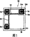
As shown in Figure 1, a QR sign indicating number 52 comprises 54, two synchronous lattice row (time cell line) 58 and end point of three telltale marks (location symbol) (ending point) 50.Telltale mark 54, synchronously lattice row and end point are used for the detection of QR sign indicating number and the initialization of information Recognition process, and the square region that they limited is the content regions 56 that comprises the information that will be reached by the QR code table.
At present, lattice row 58 are made of black-white point that replace, equally spaced synchronously, and telltale mark is made of the black box 54c that white square frame 54b surrounds, and described white square frame 54b outside also is with a dark square 54a.Any straight line that passes the relative both sides of center black box 54c can be 5 sections by the edge cuts of described square and square frame, and this ratio of 5 sections is 1: 1: 3: 1: 1, this ratio was called aspect ratio in the back.Fig. 2 .1 illustrate three center of passing square 54c that give an example relative both sides the straight line (a) and (b) and (c) (comprise diagonal line (b)).Fig. 2 .2 illustrates the waveform that forms along described rectilinear scanning telltale mark, has wherein reflected described aspect ratio.
During information in will reading the QR sign indicating number, scanning comprises the zone of QR sign indicating number, obtains bianry image (perhaps, the bianry image that comprises the QR sign indicating number may exist).Survey telltale mark then, determine the position of QR sign indicating number then with telltale mark together with synchronous lattice row and end point.Like this, just can discern content regions and read wherein content.
Generally, the QR sign indicating number is used as label or similar thing, is used to provide by some simple information of the article of label.Such quantity of information is little.In this case, on article, have only a QR sign indicating number usually, the operator only need scan comprise this QR sign indicating number small region just.
Correspondingly, traditional method and apparatus that is used to locate the QR sign indicating number is grasping or can only operate the zonule image that is of a size of or two inches during reading images, the operator must be manually or the part of semi-automatically scanner just being aimed at QR sign indicating number image place, to obtain the tram of QR sign indicating number.In addition, traditional scheme can only be located a QR sign indicating number at every turn, can only make up three telltale marks.
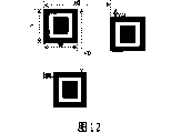
But as the latest development, the QR sign indicating number is used for expressing increasing information now, and an image can comprise a plurality of QR sign indicating numbers, for example as shown in Figure 3.In this case, traditional targeting scheme is no longer valid.
In addition, shown in Fig. 2 .1 and Fig. 2 .2, traditional targeting scheme uses center and bight sweep trace to locate the QR sign indicating number, and such method is very unreliable.
Another shortcoming of traditional scheme is that what can only be located that forward as shown in Figure 1 arranges is the QR sign indicating number of mass-tone with black.If the QR sign indicating number is inverted or with any direction placement, if perhaps image is by inverse, then traditional method is just invalid.
Summary of the invention
Consider that the problems referred to above have proposed the present invention.
Particularly, an object of the present invention is to provide a kind of method and apparatus that can position a plurality of QR sign indicating numbers in the image of any size automatically.
In order to achieve the above object, the invention provides a kind of equipment that is used at least one QR sign indicating number of positioning image, comprising: the aspect ratio sniffer is used for surveying possible QR sign indicating number telltale mark district by a plurality of exploration operations of carrying out the aspect ratio of surveying the QR sign indicating number; Crucial edge detection device is used to survey the crucial edge in described possible QR sign indicating number telltale mark district; The telltale mark composite set, the QR sign indicating number telltale mark district that is used for detecting is combined as possible QR sign indicating number; And the affirmation device, be used to get rid of false QR sign indicating number; Wherein, described crucial edge detection device also comprises: crucial edge calculations device is used for the crucial edge that result according to the output of described aspect ratio sniffer calculates described possible specifically labelled expection; The horizontal edge detector is used to confirm whether the crucial edge of the level of expecting does not comprise white pixel; And the vertical edge detector, be used to confirm whether the vertical edge of expecting does not comprise white pixel; And wherein, described affirmation device also comprises: synchronous lattice sniffer is used to survey the aspect ratio that the difference between the two-dimensional bar telltale mark is arranged with vertical direction in the horizontal direction; The end point sniffer, whether the specifically labelled bight of two-dimensional bar that do not have that is used to survey at possible two-dimensional bar exists end point.
The present invention also provides a kind of method that is used at least one QR sign indicating number of positioning image, comprising: the aspect ratio detection steps, and a plurality of exploration operations that are used for the aspect ratio by surveying the QR sign indicating number are surveyed possible QR sign indicating number telltale mark district; Crucial edge detection step is used to survey the crucial edge in possible QR sign indicating number telltale mark district; The telltale mark combination step, the QR sign indicating number telltale mark district that is used for detecting is combined as possible QR sign indicating number; And the affirmation step, be used to get rid of false QR sign indicating number.Wherein, described crucial edge detection step also comprises: crucial edge calculations step is used for the crucial edge that result according to described aspect ratio detection steps calculates described possible specifically labelled expection; The horizontal edge detection steps is used to confirm whether the crucial edge of the level of expecting does not comprise white pixel; And the vertical edge detection steps, be used to confirm whether the vertical edge of expecting does not comprise white pixel; And wherein, described affirmation step also comprises: synchronous lattice detection steps is used to survey the aspect ratio that the difference between the two-dimensional bar telltale mark is arranged with vertical direction in the horizontal direction; The end point detection steps, whether the specifically labelled bight of two-dimensional bar that do not have that is used to survey at possible two-dimensional bar exists end point.
The present invention also provides wherein storage to be used to realize the storage medium of the program code of the described method that is used to locate at least one QR sign indicating number.
Description of drawings
Other purpose of the present invention, feature and advantage will become more clear after the detailed description of preferred embodiments reading hereinafter.The accompanying drawing part of book as an illustration is used for the diagram embodiments of the invention, and is used from explanation principle of the present invention with instructions one.In the accompanying drawings:
Fig. 1 is the synoptic diagram of QR sign indicating number;
Fig. 2 .1 and 2.2 is respectively the specifically labelled synoptic diagram of QR sign indicating number, and by scanning the waveform that this telltale mark obtains, is used to illustrate specifically labelled aspect ratio;
Fig. 3 is the example of image that comprises the QR sign indicating number of a plurality of different sizes and direction;
Fig. 4 is the block diagram of an example that can realize the computer system of method and apparatus of the present invention;
Fig. 5 is the main flow chart of expression QR sign indicating number localization method of the present invention;
Fig. 6 is the process flow diagram of representation feature ratio detection process;
Fig. 7 .1 is that expression is carried out horizontal properties than 1: 1: 3 to an image line: the synoptic diagram that detection in 1: 1 is handled;
Fig. 7 .2 is that expression is carried out vertical features than 1: 1: 3 to an image line: the synoptic diagram that detection in 1: 1 is handled;
Fig. 7 .3 is an example surveying capable and three the adjacent vertical row of three adjacent levels;
Fig. 8 is the synoptic diagram of the bit-byte conversion map operation on image line of expression;
Fig. 9 is the process flow diagram of expression telltale mark edge detection process;
Figure 10 .1 is the example how an expression calculates crucial edge, and this key edge is the inner boundary of specifically labelled outer black surround;
Figure 10 .2 represents how to distinguish the example at calculated level and vertical crucial edge, and wherein, the crucial marginal point of level is marked by " H ", and vertical crucial marginal point is marked by " V ";
Figure 11 is the process flow diagram of expression QR sign indicating number telltale mark anabolic process;
Figure 12 is the synoptic diagram that is used to illustrate rule of combination;
Figure 13 represents that QR sign indicating number district checks the process flow diagram of handling;
Embodiment
Below in conjunction with accompanying drawing the preferred embodiments of the present invention are described.
Computer system for example
Method and apparatus of the present invention can be realized in any messaging device.Described messaging device for example is the single-chip microcomputer (SCM) of personal computer (PC), notebook computer, embedding camera, video camera, scanner etc., or the like.For those of ordinary skills, be easy to realize method and apparatus of the present invention by software, hardware and/or firmware.Especially it should be noted that, it is evident that for those of ordinary skills, for any step of carrying out this method or the combination of step, the perhaps any parts of equipment of the present invention or the combination of parts may need to use input-output device, memory device and microprocessor such as CPU etc.May not be certain to mention these equipment in the explanation to method and apparatus of the present invention below, but in fact used these equipment.
As above-mentioned messaging device, Fig. 4 shows giving an example of a computer system, can realize method and apparatus of the present invention therein.It should be noted that the computer system that is shown in Fig. 4 just is used for explanation, does not really want to limit the scope of the invention.
From the angle of hardware, computing machine 1 comprises a CPU6,5, RAM7 of a hard disk (HD), ROM8 and input-output device 12.Input-output device can comprise input media such as keyboard, Trackpad, tracking ball and mouse etc., and output unit is such as printer and monitor, and input-output unit is such as floppy disk, CD drive and communication port.
From the angle of software, described computing machine mainly comprises operating system (OS) 9, input/output driver 11 and various application program 10.As operating system, can use any operating system that to buy on the market, such as Window series and based on the operating system of Linux.Input/output driver is respectively applied for and drives described input-output device.Described application program can be an Any Application, such as text processor, image processing program etc., comprising can be used in this invention or can utilize existing program of the present invention and aim at the present invention's application program establishment, that can call described existing program.
Like this, in the present invention, can in the hardware of described computing machine, realize method and apparatus of the present invention by operating system, application program and input/output driver.
In addition, computing machine 1 can be connected to digital device 3 and application apparatus 2.Digital device can be camera, video camera, scanner or the digitizer that is used for analog image is converted to digital picture as image source.The result that equipment of the present invention and method obtain is output to application apparatus 2, perhaps according to described result, carries out suitable operation.This application apparatus can be implemented as the Another application program (combining with hardware) that realizes in computing machine 1, be used for further handling described image.
Be used to locate the equipment and the method for QR sign indicating number
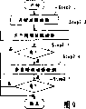
The main flow chart of Fig. 5 has been represented the key step of the method for the present invention that will be carried out by equipment of the present invention.The equipment that is used to locate at least one QR sign indicating number comprises: the aspect ratio sniffer that is used for execution in step Step1: survey possible QR sign indicating number telltale mark district by carrying out a plurality of exploration operations of surveying specifically labelled aspect ratio; The crucial edge detection device that is used for execution in step Step 2: survey the crucial edge in possible QR sign indicating number telltale mark district, so that get rid of false district; The telltale mark composite set that is used for execution in step Step 3: the QR sign indicating number telltale mark district that detects is combined as possible QR sign indicating number; And the affirmation device that is used for execution in step Step 4, be used to get rid of false QR sign indicating number.
The aspect ratio sniffer can come execution in step Step 1 with traditional method and corresponding device thereof (such as Fig. 2 .1 and Fig. 2 .2 those shown).In the present invention, the inventor provides new device to come execution in step Step 1.Particularly, horizontal properties ratio detection device and vertical features ratio detection device are provided.Fig. 6 illustrate survey one by horizontal properties ratio detection device and vertical features ratio detection device being used to of carrying out may specifically labelled process.As shown in Figure 6, in the step Step 1.1 that horizontal properties ratio detection device is carried out, survey, see whether exist the horizontal line that comprises aspect ratio (to that is to say, at least a portion of this row comprises black subdivision and white subdivision, and their length ratio equals 1: 1: 3: 1: 1) (step Step 1.2).If exist, then by vertical features ratio detection device execution in step Step 1.3: one with the crossing vertical row of the central black subdivision of the described part that detects in survey.If in the vertical row that is detected, there is described aspect ratio (step Step 1.4), can determine that then the squared region that is limited by described horizontal line and described vertical row part is possible telltale mark.
In a preferred embodiment of the invention, if horizontal properties ratio detection device and vertical features ratio detection device have detected described horizontal line part and described vertical row part respectively, then detection process moves to next adjacent scan line (being respectively level and vertical scan line) (step Step 1.5).Repeat twice of said process, only when in three horizontal line and three vertical row, all detecting described aspect ratio (step Step 1.6), corresponding square region just is regarded as possible telltale mark, and as shown in Figure 6 the new process of carrying out is to seek next possible telltale mark; Otherwise for the next horizontal line repetition said process that starts anew.
Fig. 7 .1 illustrates the example how horizontal properties ratio detection device carries out step Step 1.1.In the horizontal line that is detected of image, each pixel has " 1 " (black pixel) or " 0 " (white pixel) value.Connected pixel is counted, obtained a sequence, can obtain a ratio from this sequence.Itself and aspect ratio can be compared then, see whether mate.
Fig. 7 .2 illustrates the example how vertical features ratio detection device carries out step Step 1.2.Except row be vertical but not level, others be the same shown in Fig. 7 .1.
The synoptic diagram of Fig. 7 .3 is used for illustrating in another way process shown in Figure 6.When surveying telltale mark, scanning element row one by one from top to bottom.After detecting the first horizontal line H1 that comprises aspect ratio, survey and the first crossing vertical row V1 of the central black subdivision of this first horizontal line H1, thereby see whether it also comprises aspect ratio and can constitute a telltale mark with the first horizontal line H1.Further survey the second horizontal line H2, the second vertical row V2, the 3rd horizontal line H3 and the 3rd vertical row V3 then, see whether they also comprise aspect ratio corresponding to first horizontal line and first vertical row.If the result in each top step is sure, then can determine a possible telltale mark shown in Fig. 7 .3.About detection direction, not necessarily from top to bottom.Also can be from top to bottom, from left to right or from right to left.
In order to improve the speed of this method and equipment, reduce memory consumption, the present invention further provides a kind of method and apparatus of novelty of detection feature ratio.Particularly, the invention provides conversion equipment, be used for the row (perhaps before step Step 1) before above-mentioned steps Step 1.1 and Step 1.3 that will survey is carried out pre-service.
Particularly, in a bianry image, a pixel is corresponding to a bit in the internal memory.The black pixel of value " 1 " representative, value " 0 " is represented white pixel.As preceding with reference to as described in Fig. 6, Fig. 7 .1 and Fig. 7 .2, when detection feature than the time, the present invention need count connected pixel.Traditionally, this need count the adjacent bit with identical value.Just, need operate bit.Yet known to us, in present any information equipment, information all is to use byte representation.This problem can greatly reduce processing speed, increases memory consumption.
In order to address this problem, it is a byte with each bit expanded that the inventor puts forward with conversion equipment.As shown in Figure 8, if row comprise N pixel (N=8m, m are natural numbers, here, as an example, N=16), N bit (m byte) just, then this is about to be expanded and is N byte.For n pixel of black (n=1,2,3......N) (just) for n the bit that is " 1 ", (n mod 8) individual bit of n byte is set to 1, other bit of these N byte all is set to 0.Then, can carry out the counting operation of step Step 1.1 and Step 1.3, because only there are two kinds of bytes: zero byte and non-zero byte to this N byte.The benefit that adopts this conversion equipment is to have simplified the aspect ratio exploration operation, because operation is directly carried out on byte, rather than bit is operated.When recovering pixel column, only need carry out the respective byte that the OR operation just can recover pixel column to per 8 conversion bytes.
Fig. 9, Figure 10 .1 and Figure 10 .2 illustrate the object lesson of the step Step 2 that is carried out by crucial edge detection device.This key edge detection device comprises a crucial edge calculations device, a horizontal edge detector and a vertical edge detector.In step Step 2.1,, for example shown in Fig. 7 .3, find out crucial marginal point C with crucial edge calculations device, shown in Figure 10 .1 based on the result of step 1.Just, for example,, can expect one by deceiving the square frame that pixel C forms from the result of Fig. 7 .3.
Then, at step Step 2.2, the horizontal edge detector confirms whether the horizontal edge H of expection does not comprise white pixel really; At step Step 2.4, the vertical edge detector confirms that the vertical edge V of expection does not comprise white pixel really.Have only the horizontal edge of working as and vertical edge all to obtain confirming (step Step 2.3 and Step 2.5), corresponding telltale mark just is confirmed to be possible telltale mark.
Of the present invention next step is that described telltale mark is combined as possible QR sign indicating number (step Step 3).For this reason, this telltale mark composite set comprises a comparer and a sorter.At step Step 3.1 (Figure 11), comparer calculates each specifically labelled width W and height H, and horizontal range HD between the adjacent positioned mark and vertical range VD, as shown in figure 12.
At step Step 3.2, the W of the comparer comparison first telltale mark A and H and first telltale mark and adjacent positioned mark thereof are such as HD between B and the C and VD then.If HD>W and VD<=H, then these two corresponding telltale marks (A and B) should be got up by horizontal combination (step Step 3.3).If HD<=W and VD>H (step Step 3.4), then these two corresponding telltale marks (A and C) should be got up by vertical cartel (step Step3.5).If a telltale mark and two other telltale mark be horizontal combination and vertical cartel respectively, then these three telltale marks constitute a possible QR sign indicating number.Repeat said process (step Step 3.6), all be grouped up to all telltale marks.
In a preferred embodiment, described composite set can also comprise overlapping pick-up unit, is used to detect overlapping between the QR sign indicating number, thereby gets rid of false coupling.
So just obtained possible QR sign indicating number.At next procedure Step 4, confirm by the affirmation device, to get rid of false QR sign indicating number.This affirmation device comprises synchronous lattice (timing cell) sniffer and end point sniffer.At step Step 4.1, (1: 1: 1...), whether the lattice detection existed synchronous lattice row 58 between the telltale mark of two horizontal combination synchronously by surveying synchronous lattice aspect ratio.At step Step 4.3, (1: 1: 1...), whether the lattice detection existed synchronous lattice row 58 (see figure 1)s between the telltale mark of two vertical cartels synchronously by surveying synchronous lattice aspect ratio.Detection method is similar to surveys the employed method of telltale mark aspect ratio as mentioned above, here repeats no more.At last, at step Step 4.5, whether the end point detection exists an end point in the specifically labelled bight of QR sign indicating number that do not have of possible QR sign indicating number.When the result who only works as above-mentioned all three steps is sure (step Step 4.2, Step 4.4 and Step4.6), just confirm the QR sign indicating number that this is possible.
Storage medium
Described purpose of the present invention can also be by realizing with program of operation or batch processing on any messaging device that described image source is communicated by letter with subsequent processing device aforesaid.Described messaging device, image source and subsequent processing device are known common apparatus.Therefore, described purpose of the present invention also can be only by providing the program code of realizing described method or equipment to realize.That is to say that the storage medium that stores the program code of realizing described method or equipment constitutes the present invention.
To those skilled in the art, can realize described method with any program language programming easily.Therefore, omitted detailed description at this to described program code.
Obviously, described storage medium can be well known by persons skilled in the art, and perhaps therefore the storage medium of any kind that is developed in the future also there is no need at this various storage mediums to be enumerated one by one.
From as can be known above-mentioned, the present invention has following advantage:
1. the present invention can the big infinite region image of high speed processing, and memory consumption is low, can be used in the vision facilities of any kind of;
2. the present invention can locate the QR code position automatically, need not be concerned about whether image needs to adjust in advance;
3. the present invention can be by all the QR sign indicating numbers in the single pass framing image;
4. the present invention can provide stablizing of a kind of QR of location sign indicating number accurate scheme;
5. the present invention can find out the different directions of black or white QR sign indicating number simultaneously.
The present invention can be applied to scanner, monitor, camera or other any image processing system that comprises computing machine, the exact position that can successfully obtain each QR sign indicating number in the binary document image that comprises a plurality of QR sign indicating numbers.
Although in conjunction with concrete steps and structrual description the present invention, the present invention is not limited to details as described herein.The application should cover all variation, modification and modification without departing from the spirit and scope of the present invention.
Claims (12)
1. equipment that is used at least one two-dimensional bar of positioning image comprises:
The aspect ratio sniffer is used for: by carrying out a plurality of exploration operations of surveying specifically labelled aspect ratio, survey possible two-dimensional bar telltale mark district;
Crucial edge detection device is used to survey the crucial edge in possible two-dimensional bar telltale mark district;
The telltale mark composite set, the two-dimensional bar telltale mark district coupling that is used for detecting is possible two-dimensional bar; And
Confirm device, be used to get rid of false two-dimensional bar;
Wherein, described crucial edge detection device also comprises: crucial edge calculations device is used for the crucial edge that result according to the output of described aspect ratio sniffer calculates described possible specifically labelled expection; The horizontal edge detector is used to confirm whether the crucial edge of the level of expecting does not comprise white pixel; And the vertical edge detector, be used to confirm whether the vertical edge of expecting does not comprise white pixel; And
Wherein, described affirmation device also comprises: synchronous lattice sniffer is used to survey the aspect ratio that the difference between the two-dimensional bar telltale mark is arranged with vertical direction in the horizontal direction; The end point sniffer, whether the specifically labelled bight of two-dimensional bar that do not have that is used to survey at possible two-dimensional bar exists end point.
2. equipment as claimed in claim 1 is characterized in that, described aspect ratio sniffer also comprises:
Horizontal properties ratio detection device is used for the aspect ratio of the horizontal line of detection image; And
Vertical features ratio detection device is used for surveying the aspect ratio according to the selected vertical row of result of detection of described horizontal properties ratio detection device.
3. equipment as claimed in claim 2 is characterized in that:
Described horizontal properties ratio detection device further is configured to: after detecting first horizontal line that comprises described aspect ratio, survey two aspect ratios of adjoining in the horizontal line; And
Described vertical features ratio detection device further is configured to: survey according to the aspect ratio in selected three the adjacent vertical row of the result of detection of described horizontal properties ratio detection device.
4. as claim 2 or 3 described equipment, it is characterized in that described aspect ratio sniffer also comprises conversion equipment, the row that will be detected that is used for comprising the N pixel is converted to N byte, wherein, N=8m, m are natural number, n pixel for black, n=1,2 ... N, (n mod 8) individual bit of n byte is set to " 1 ", and
Described horizontal properties ratio detection device and described vertical features ratio detection device carry out described exploration operation to a described N byte.
5. equipment as claimed in claim 1 is characterized in that, described telltale mark composite set also comprises:
Comparer is used to calculate each possible specifically labelled width W and height H, and horizontal range HD and vertical range VD between two adjacent positioned marks, and relatively they;
Sorter, if HD>W and VD<=H, then with telltale mark and the grouping of adjacent positioned mark level thereof, if HD<=W and VD>H, then with telltale mark and the vertical grouping of adjacent positioned mark thereof.
6. equipment as claimed in claim 5 is characterized in that, described telltale mark composite set also comprises overlapping pick-up unit, is used to detect overlapping between the two-dimensional bar, thereby gets rid of false combination.
7. method that is used at least one two-dimensional bar of positioning image comprises:
The aspect ratio detection steps is used for: by carrying out a plurality of exploration operations of surveying specifically labelled aspect ratio, survey possible two-dimensional bar telltale mark district;
Crucial edge detection step is used to survey the crucial edge in possible two-dimensional bar telltale mark district;
The telltale mark combination step, the two-dimensional bar telltale mark district coupling that is used for detecting is possible two-dimensional bar; And
Confirm step, be used to get rid of false two-dimensional bar;
Wherein, described crucial edge detection step also comprises: crucial edge calculations step is used for the crucial edge that result according to described aspect ratio detection steps calculates described possible specifically labelled expection; The horizontal edge detection steps is used to confirm whether the crucial edge of the level of expecting does not comprise white pixel; And the vertical edge detection steps, be used to confirm whether the vertical edge of expecting does not comprise white pixel; And
Wherein, described affirmation step also comprises: synchronous lattice detection steps is used to survey the aspect ratio that the difference between the two-dimensional bar telltale mark is arranged with vertical direction in the horizontal direction; The end point detection steps, whether the specifically labelled bight of two-dimensional bar that do not have that is used to survey at possible two-dimensional bar exists end point.
8. method as claimed in claim 7 is characterized in that, described aspect ratio detection steps also comprises:
Horizontal properties ratio detection step is used for the aspect ratio of the horizontal line of detection image; And
Vertical features ratio detection step is used for surveying the aspect ratio according to the selected vertical row of result of detection of described horizontal properties ratio detection step.
9. method as claimed in claim 8 is characterized in that:
Described horizontal properties ratio detection step comprises: after detecting first horizontal line that comprises described aspect ratio, survey two aspect ratios of adjoining in the horizontal line; And
Described vertical features ratio detection step comprises: survey according to the aspect ratio in selected three the adjacent vertical row of the result of detection of described horizontal properties ratio detection step.
10. method as claimed in claim 8 or 9 is characterized in that, before described horizontal properties ratio detection step and vertical features ratio detection step, described aspect ratio detection steps also comprises switch process, and the row that will be detected that is used for comprising the N pixel is converted to N byte, wherein, N=8m, m is a natural number, for n pixel of black, n=1,2, ..N, (n mod 8) individual bit of n byte is set to " 1 ", and
Described horizontal properties ratio detection step and described vertical features ratio detection step are carried out described exploration operation to a described N byte.
11. method as claimed in claim 7 is characterized in that, described telltale mark combination step also comprises:
Comparison step is used to calculate each specifically labelled width W and height H, and horizontal range HD and vertical range VD between two adjacent positioned marks, and relatively they;
Classification step, if HD>W and VD<=H, then with telltale mark and the grouping of adjacent positioned mark level thereof, if HD<=W and VD>H, then with telltale mark and the vertical grouping of adjacent positioned mark thereof.
12. method as claimed in claim 11 is characterized in that, described telltale mark combination step also comprises overlapping detection step, is used to detect overlapping between the two-dimensional bar, thereby gets rid of false combination.
Priority Applications (3)
| Application Number | Priority Date | Filing Date | Title |
|---|---|---|---|
| CNB2004100768154A CN100347714C (en) | 2004-09-07 | 2004-09-07 | Method, device and recording medium for positioning bar code |
| US11/202,106 US7273175B2 (en) | 2004-09-07 | 2005-08-12 | Method, an apparatus and a storage medium for locating QR codes |
| JP2005258311A JP4154413B2 (en) | 2004-09-07 | 2005-09-06 | Method, apparatus, and storage medium for confirming position of QR code |
Applications Claiming Priority (1)
| Application Number | Priority Date | Filing Date | Title |
|---|---|---|---|
| CNB2004100768154A CN100347714C (en) | 2004-09-07 | 2004-09-07 | Method, device and recording medium for positioning bar code |
Publications (2)
| Publication Number | Publication Date |
|---|---|
| CN1746898A CN1746898A (en) | 2006-03-15 |
| CN100347714C true CN100347714C (en) | 2007-11-07 |
Family
ID=36158964
Family Applications (1)
| Application Number | Title | Priority Date | Filing Date |
|---|---|---|---|
| CNB2004100768154A Expired - Fee Related CN100347714C (en) | 2004-09-07 | 2004-09-07 | Method, device and recording medium for positioning bar code |
Country Status (3)
| Country | Link |
|---|---|
| US (1) | US7273175B2 (en) |
| JP (1) | JP4154413B2 (en) |
| CN (1) | CN100347714C (en) |
Families Citing this family (53)
| Publication number | Priority date | Publication date | Assignee | Title |
|---|---|---|---|---|
| WO2009044720A1 (en) * | 2007-10-02 | 2009-04-09 | B-Core Inc. | Optical recognition code reading method, device, and program, and printed object marked with optical recognition code |
| CN101482933B (en) * | 2008-01-08 | 2010-09-01 | 纬创资通股份有限公司 | Identification data generation method used for high-speed recognition code and its correlated apparatus |
| US20100084470A1 (en) * | 2008-10-03 | 2010-04-08 | Microsoft Corporation | Two-dimensional barcode localization for camera based devices |
| US9355293B2 (en) * | 2008-12-22 | 2016-05-31 | Canon Kabushiki Kaisha | Code detection and decoding system |
| TW201113815A (en) * | 2009-10-09 | 2011-04-16 | Primax Electronics Ltd | QR code processing method and apparatus thereof |
| US20110290882A1 (en) * | 2010-05-28 | 2011-12-01 | Microsoft Corporation | Qr code detection |
| AU2011203186A1 (en) | 2010-07-01 | 2012-01-19 | Aristocrat Technologies Australia Pty Limited | A method of gaming, a gaming system, and a game controller |
| AU2010257441B2 (en) * | 2010-12-24 | 2012-09-20 | Canon Kabushiki Kaisha | Method, apparatus and system for identifying candidate pairs of finder patterns of a barcode |
| US8439275B2 (en) | 2011-04-06 | 2013-05-14 | Eastman Kodak Company | Multi-resolution optical codes |
| US8807435B2 (en) | 2011-04-06 | 2014-08-19 | Eastman Kodak Company | Decoding multi-resolution optical codes |
| US8665472B2 (en) | 2011-04-27 | 2014-03-04 | Intellectual Ventures Fund 83 Llc | Producing an image and optical file from a visible first digital image and from a visible second digital image of a machine-readable optical code which encodes information associated with or derived from the first digital image |
| US8763904B2 (en) | 2011-04-27 | 2014-07-01 | Intellectual Ventures Fund 83 Llc | Visibly forming an image and optical code |
| US8511575B2 (en) | 2011-04-27 | 2013-08-20 | Intellectual Ventures Fund 83 Llc | Digital image file including optical code |
| US8463765B2 (en) | 2011-04-29 | 2013-06-11 | Zachary C. LESAVICH | Method and system for creating vertical search engines with cloud computing networks |
| JP5362058B2 (en) * | 2011-05-17 | 2013-12-11 | 東芝テック株式会社 | Code reader and program |
| US8967482B2 (en) | 2011-05-23 | 2015-03-03 | Intellectual Ventures Fund 83 Llc | Image selection method using machine-readable codes |
| CN102810151B (en) * | 2011-06-02 | 2015-10-21 | 航天信息股份有限公司 | Capacity-priority special-shape matrix type two-dimensional barcode arrangement method |
| US8596523B2 (en) | 2011-07-28 | 2013-12-03 | Intellectual Ventures Fund 83 Llc | Index print with machine-readable codes |
| US8646691B2 (en) | 2011-09-13 | 2014-02-11 | Intellectual Ventures Fund 83 Llc | Apparatus and method for using machine-readable codes |
| CN102346850B (en) * | 2011-10-13 | 2013-08-14 | 西北工业大学 | DataMatrix bar code area positioning method under complex metal background |
| US8534542B2 (en) | 2012-01-17 | 2013-09-17 | Intellectual Ventures Fund 83 Llc | Making an ordered element list |
| US9082131B2 (en) | 2012-01-30 | 2015-07-14 | Topcon Positioning Systems, Inc. | Method and apparatus for tracking items and providing item information |
| US9038917B2 (en) * | 2012-02-01 | 2015-05-26 | Optoelectronics Co. Ltd. | System and method for noise reduction in a bar code signal |
| US8634651B2 (en) * | 2012-02-29 | 2014-01-21 | Accusoft Corporation | Methods and apparatus for locating target patterns in an image |
| US8651370B1 (en) | 2012-05-10 | 2014-02-18 | Orion Photo Industries, Inc. | System for providing coded personalized souvenirs |
| CN102779264B (en) * | 2012-07-10 | 2015-05-13 | 北京恒信彩虹科技有限公司 | Method and device for realizing barcode recognition |
| GB2518443A (en) | 2013-09-24 | 2015-03-25 | Ibm | Method for detecting phishing of a matrix barcode |
| CN103473527A (en) * | 2013-09-25 | 2013-12-25 | 中山爱科数字科技股份有限公司 | Improved two-dimension code label recognition method |
| CN104517090B (en) * | 2013-09-29 | 2017-09-05 | 北大方正集团有限公司 | A kind of QR codes detect the detection method and system of figure |
| CN104517108B (en) * | 2013-09-29 | 2017-12-22 | 北大方正集团有限公司 | A kind of method and system of determination QR code binary image edge lines |
| CN103701586A (en) * | 2013-11-07 | 2014-04-02 | 金硕澳门离岸商业服务有限公司 | Method and device for acquiring secret key |
| TWI509528B (en) * | 2013-12-13 | 2015-11-21 | Univ Nat Taiwan | Stylized qr code generating apparatus and method thereof |
| USD757094S1 (en) * | 2014-04-29 | 2016-05-24 | Tencent Technology (Shenzhen) Company Limited | Display screen portion with animated graphical user interface |
| US10083332B2 (en) * | 2014-08-08 | 2018-09-25 | Intel Corporation | QR image based device management |
| JP6677037B2 (en) | 2016-03-23 | 2020-04-08 | 富士ゼロックス株式会社 | Information processing device, image reading device, and program |
| CN107895275A (en) * | 2017-11-28 | 2018-04-10 | 北京信用达互联网信息技术有限公司 | The product preventing counterfeiting means of proof |
| US10366315B1 (en) | 2018-08-15 | 2019-07-30 | Fmr Llc | Generating a quick response (QR) grid associated with a digital document |
| JP7021651B2 (en) * | 2019-03-01 | 2022-02-17 | オムロン株式会社 | Symbol boundary identification device, symbol boundary identification method and image processing program |
| US10509991B1 (en) | 2019-03-18 | 2019-12-17 | Capital One Services, Llc | Detection of images in relation to targets based on colorspace transformation techniques and utilizing infrared light |
| US10496911B1 (en) | 2019-03-18 | 2019-12-03 | Capital One Services, Llc | Detection of images in relation to targets based on colorspace transformation techniques and utilizing ultraviolet and infrared light |
| US10534948B1 (en) | 2019-03-18 | 2020-01-14 | Capital One Services, Llc | Optimizing detection of images in relation to targets based on colorspace transformation techniques |
| US10496862B1 (en) | 2019-03-18 | 2019-12-03 | Capital One Services, Llc | Detection of images in relation to targets based on colorspace transformation techniques and utilizing ultraviolet light |
| US10523420B1 (en) | 2019-04-18 | 2019-12-31 | Capital One Services, Llc | Transmitting encoded data along transmission mediums based on colorspace schemes |
| US10504013B1 (en) | 2019-04-24 | 2019-12-10 | Capital One Services, Llc | Colorspace encoding multimedia data on a physical page |
| US10529300B1 (en) | 2019-06-20 | 2020-01-07 | Capital One Services, Llc | Adaptive image display based on colorspace conversions |
| US10614635B1 (en) | 2019-07-25 | 2020-04-07 | Capital One Services, Llc | Augmented reality system with color-based fiducial marker |
| WO2021046173A1 (en) | 2019-09-06 | 2021-03-11 | Vitiprints, LLC | Image and quick art response code system |
| US10833852B1 (en) | 2019-10-03 | 2020-11-10 | Capital One Services, Llc | Encoded data along tape based on colorspace schemes |
| US10715183B1 (en) | 2019-10-25 | 2020-07-14 | Capital One Services, Llc | Data encoding with error-correcting code pursuant to colorspace schemes |
| US10867226B1 (en) | 2019-11-04 | 2020-12-15 | Capital One Services, Llc | Programmable logic array and colorspace conversions |
| US10762371B1 (en) | 2019-11-14 | 2020-09-01 | Capital One Services, Llc | Object detection techniques using colorspace conversions |
| US10878600B1 (en) | 2019-12-10 | 2020-12-29 | Capital One Services, Llc | Augmented reality system with color-based fiducial marker utilizing local adaptive technology |
| US11302036B2 (en) | 2020-08-19 | 2022-04-12 | Capital One Services, Llc | Color conversion between color spaces using reduced dimension embeddings |
Citations (3)
| Publication number | Priority date | Publication date | Assignee | Title |
|---|---|---|---|---|
| CN1079321A (en) * | 1992-05-29 | 1993-12-08 | 欧林巴斯光学工业股份有限公司 | Apparatus for reading of bar code |
| CN1092191A (en) * | 1992-06-25 | 1994-09-14 | 欧林巴斯光学工业股份有限公司 | The record body that has removable two-dimensional code |
| CN1455370A (en) * | 2002-04-29 | 2003-11-12 | 深圳矽感科技有限公司 | Two-dimensional barcode card and its decoding method |
Family Cites Families (2)
| Publication number | Priority date | Publication date | Assignee | Title |
|---|---|---|---|---|
| JP4122629B2 (en) * | 1998-09-03 | 2008-07-23 | 株式会社デンソー | 2D code generation method |
| JP4301775B2 (en) * | 2002-07-18 | 2009-07-22 | シャープ株式会社 | Two-dimensional code reading device, two-dimensional code reading method, two-dimensional code reading program, and recording medium for the program |
-
2004
- 2004-09-07 CN CNB2004100768154A patent/CN100347714C/en not_active Expired - Fee Related
-
2005
- 2005-08-12 US US11/202,106 patent/US7273175B2/en active Active
- 2005-09-06 JP JP2005258311A patent/JP4154413B2/en not_active Expired - Fee Related
Patent Citations (3)
| Publication number | Priority date | Publication date | Assignee | Title |
|---|---|---|---|---|
| CN1079321A (en) * | 1992-05-29 | 1993-12-08 | 欧林巴斯光学工业股份有限公司 | Apparatus for reading of bar code |
| CN1092191A (en) * | 1992-06-25 | 1994-09-14 | 欧林巴斯光学工业股份有限公司 | The record body that has removable two-dimensional code |
| CN1455370A (en) * | 2002-04-29 | 2003-11-12 | 深圳矽感科技有限公司 | Two-dimensional barcode card and its decoding method |
Also Published As
| Publication number | Publication date |
|---|---|
| CN1746898A (en) | 2006-03-15 |
| JP2006079615A (en) | 2006-03-23 |
| JP4154413B2 (en) | 2008-09-24 |
| US20060082475A1 (en) | 2006-04-20 |
| US7273175B2 (en) | 2007-09-25 |
Similar Documents
| Publication | Publication Date | Title |
|---|---|---|
| CN100347714C (en) | Method, device and recording medium for positioning bar code | |
| US11538235B2 (en) | Methods and apparatus to determine the dimensions of a region of interest of a target object from an image using target object landmarks | |
| US7580576B2 (en) | Stroke localization and binding to electronic document | |
| CN1691050A (en) | 2D rectangular code symbol scanning device and 2D rectangular code symbol scanning method | |
| KR100942122B1 (en) | Local localization using fast image match | |
| CN100351839C (en) | File searching and reading method and apparatus | |
| CN1542656A (en) | Information processing apparatus, method, storage medium and program | |
| CN1908955A (en) | Trilateral poly-dimensional bar code easy for omnibearing recognition and reading method thereof | |
| CN1637775A (en) | Positionally encoded document image analysis and labeling | |
| MXPA02000110A (en) | Recording of information. | |
| CN1514397A (en) | Human ege detecting method, apparatus, system and storage medium | |
| JP2005235185A (en) | Stroke localization by m-array decoding and fast image matching | |
| JP2005164323A (en) | Mark for position detection, method and device for mark detection, and program for same | |
| TWI423146B (en) | Method and system for actively detecting and recognizing placards | |
| US9100518B2 (en) | Information processing apparatus, information processing method, and computer-readable medium | |
| JP5673257B2 (en) | Code reading apparatus, code reading method and code reading program | |
| CN1806255A (en) | Information presentation apparatus and information presentation method | |
| CN1217291C (en) | Cmnibearing information synchronous two-dimensional bar code system and reading method | |
| CN101833640B (en) | The empty boundary pixel point computing module of bar and computing method thereof | |
| JP2015191531A (en) | Determination method of spatial position of two-dimensional code, and device therefor | |
| US8649055B2 (en) | Image processing apparatus and computer readable medium | |
| CN1924898A (en) | Distorted QR code image correction method | |
| CN1110018C (en) | Eigenvalue extracting method and equipment, storage medium for memory image parser | |
| CN1637406A (en) | Method and apparatus for discriminating media for image formation | |
| KR101911912B1 (en) | Method And Device For Object Detection By Using Edge And Histogram |
Legal Events
| Date | Code | Title | Description |
|---|---|---|---|
| C06 | Publication | ||
| PB01 | Publication | ||
| C10 | Entry into substantive examination | ||
| SE01 | Entry into force of request for substantive examination | ||
| C14 | Grant of patent or utility model | ||
| GR01 | Patent grant | ||
| CF01 | Termination of patent right due to non-payment of annual fee |
Granted publication date: 20071107 Termination date: 20210907 |
|
| CF01 | Termination of patent right due to non-payment of annual fee |